

Graphic Whizard GW 800, Finishmaster 100 Reference Manual
2283 Argentia Road, Suite 21; Mississauga, Ontario; Canada L5N 5Z2; Tel: (905) 858-7663 Fax: (905) 858-4419 Toll Free 1-800-265-3376
Web Site: www.graphicwhizard.com
GW 8000
Reference
Manual
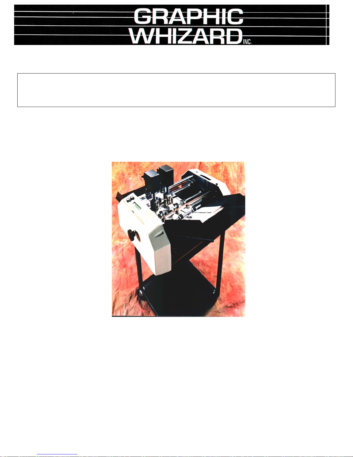
Shown with optional second head
Phone # (905) 858-7663 Fax # (905) 858-4419
Web Site: www.graphicwhizard.com
GRAPHIC WHIZARD
2283 Argentia Road, Suite #21
Mississauga, Ontario L5N 5Z2
Toll Free: 1-800-265-3376
Version 99-04

GW 8000 - Reference Manual
Table of Contents
Page
1.0 General Operation 2
2.0 Machine Assembly 3
2.1 Power Supply Instructions 3
2.2 Feed & Exit Trays 4
2.3 Numbering Heads 5
2.4 Optional Conveyor Outfeed Plate 6
2.5 Additional Switches and Controls 6
3.0 Operating Keyboard 7
3.1 Running a Job 8
3.2 Stopping a Job 10
3.3 Changing Programs 10
3.4 Programming a Job 11
3.5 The Batch Function 13
3.6 The Repeat Function 14
3.7 Motor Speed Control 14
4.0 Setting Up a Job 15
4.1 Aligning the Feed Tray Guides 15
4.2 Setting Feed Tire Pressure 15
4.3 Perforating/Slitting 17
4.4 Scoring 19
4.5 Idler Wheel Holders 19
4.6 Main Rollers 19
4.7 Installing Ink Pads 20
4.8 Locating the Numbering Heads 20
4.9 Setting Impression Control 21
4.10 Flatness of Impression 22
4.11 Stripper Assembly 23
5.0 Running a Job 24
5.1 Setting the Starting Number 24
5.2 Setting the Repeat Selector 25
5.3 Fanning 25
6.0 Maintenance 27
6.1 Numbering Heads 27
6.2 Machine Cleaning 27
6.3 Lubrication 28
6.4 Friction Feed 28
7.0 Troubleshooting 29
Friction Feeder 29
Print Quality 29
Registration 30
Numbering Heads 30
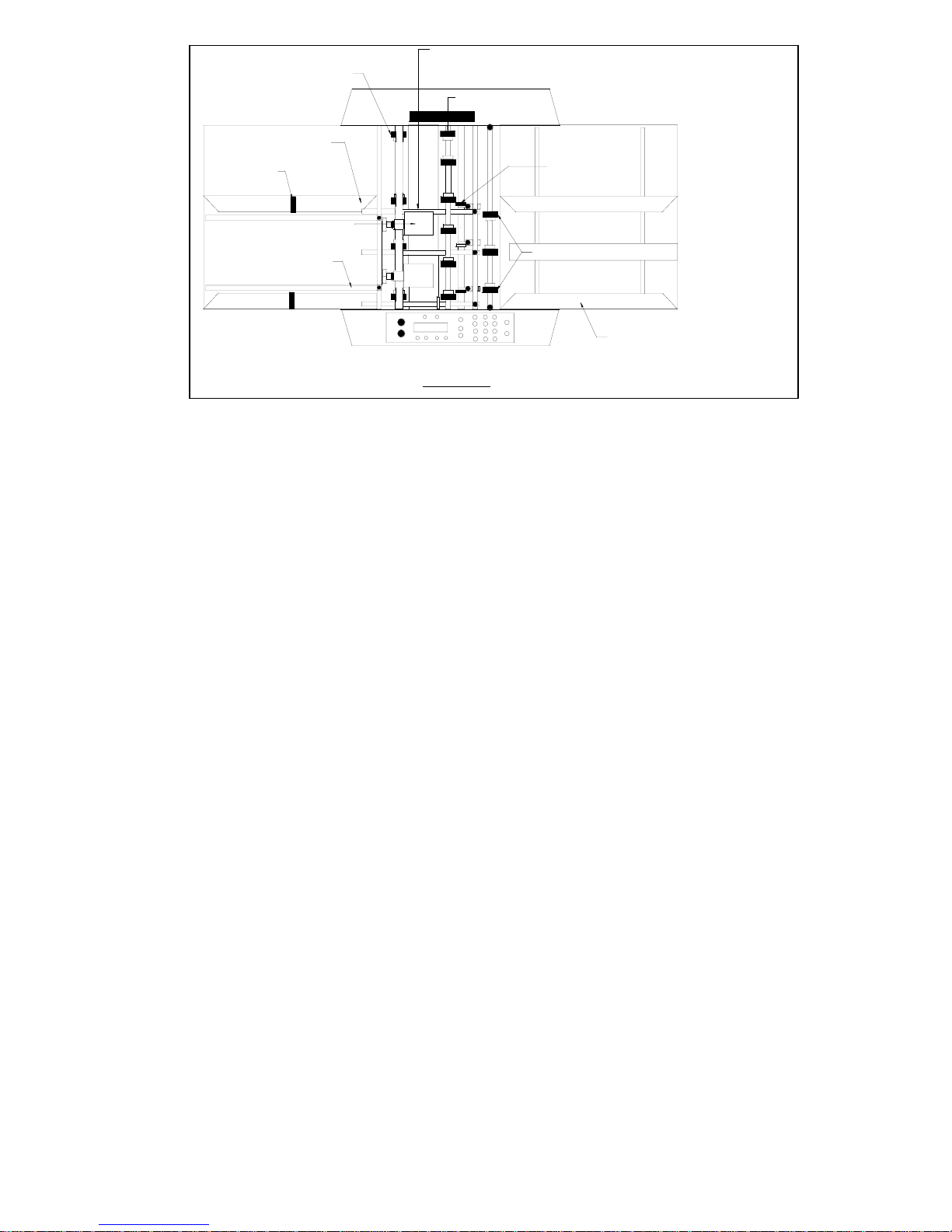
Exit tires, like the main tires should be placed so that one is on each end of the shaft
and the 2 remaining spread out across the shaft. Make sure an exit tire does not follow
a numbering head, you may track ink down the rest of the stock as it exits.
Exit tray guides are spaced to catch the finished
stock but do not to be as tight as the feed tray guides.
Magnets are placed in the guides
to act as a backstop for the stock
as it exits the machine.
Numbering Heads can be positioned along the shaft
and numbering positions are then programmed. For
each job, the numbering heads should be levelled for
the best impression.
Exit strippers help to direct the finished stock into
the exit tray, especially lighter stocks that may curl.
Strippers are to be placed close to where a numbering head is located or close to an accessory holder
when perf/score/slitting to hold down the stock at that position. The strippers help to guide the stock
through the machine. Make sure the strippers do NOT interfer with tires or the numbering wheels.
Tires on the main shaft should be placed
with one on each end of the shaft and the
remaining spread out over the shaft with a
majority used to transport the stock.
Idler tires are set so that they just
turn as the machine is in operation.
Position of the Idler tires should be
to the outside edges of the stock.
Outside feed tires set in 1 1/2" from edges of stock
Feed tray side guides set to width of stock. Operator Side
guide set all the way to the operators side to ensure staock
passes directly under photocell.
GW 8000 LAYOUT
1.0 General Operation
The Model GW 8000 can number on single sheets (12# bond to 12 point
card or 45 to 250 gsm paper) or multi-part carbonless forms (up to 10 parts) while
simultaneously perforating, slitting and/or scoring. With proper set-up, 8000
sheets per hour (8.5” x 11” stock with one hit) can be quickly and identically
processed. The Model GW 8000 is microprocessor controlled, making it easy to
set up and program. It has the programmability to hold a maximum of 99 jobs with
10 hits and 1 job with 100 hits. These jobs can all be stored and recalled for future
use. The unique friction feeder sends through one set at a time, even from the
unglued side of a padded set. Perforations are done between the register board and
main rollers, producing a straight perforation, slit or score, avoiding tail whip.
Perforating wheels are offered in a wide range of teeth configurations and can be
quickly changed using the retaining ring pliers supplied. A photocell recognises
the lead edge of the sheet and the microprocessor stops the sheet at the specific
location(s) where numbers are required. The numbering heads allow for a
maximum of four pneumatically driven units. Pneumatics allows for non-stop,
tireless operation. Finished stock is then delivered to a exit tray.
Page 2
2.0 Machine Assembly
Remove and unpack all machine parts from the shipping carton.
2.1 Power Supply Instructions
Before connecting the power cord to a wall receptacle, make certain the supply voltage is
what the machine has been set up for. The voltage is marked on the sticker containing the serial
number of the machine. If there is any discrepancies, please call your dealer first before
plugging in the machine.
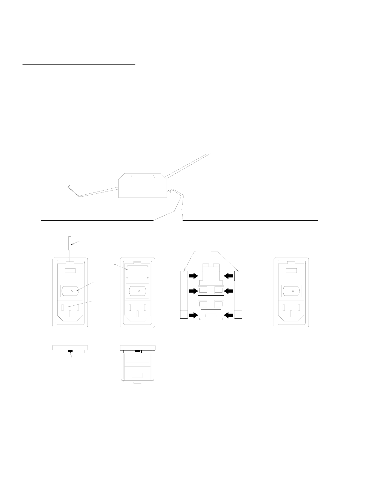
The switch module is located behind the main operator side panel, directly underneath the
register board. It also houses the main fuse.
CHANGING THE FUSE IN THE SWITCH MODULE
SCREWDRIVER
FUSE
HOLDER
ON/OFF
SWITCH
CORD
RECEPTACLE
LIP
INSERT SCREWDRIVER
INTO LIP OF THE FUSE
FRAME.
OPEN THE FUSE FRAME
DOOR AND PULLOUT THE
RED FUSE HOLDER.
FUSES
INSERT TWO SLOW BLOW
FUSES RATED 250V 5A FOR
A SUPPLY VOLTAGE OF 120V.
THESE FUSES ARE 1/4 INCH
WIDE BY 1 1/4 INCHES LONG.
INSERT THE FUSE HOLDER
BACK INTO THE UNIT FRAME
WITH THE 115V SHOWING
THROUGH THE WINDOW.
Page 3

2.2 Feed and Exit Trays
The feed and exit tray assemblies are comprised of four
components each: the tray, two tray side guides and a centre slot
cover (see
Figure 1a).
The trays sit in the machine on mounting pins inside the
machine's side frames as shown in
Figure 1b and 1c. The trays
can be easily removed and stored elsewhere when not in use.
Place the tray side guides, bottom flange towards the centre and
the centre slot cover on the tray as shown in
Figure 1a and
screw on the nylon wing nuts to secure the pieces on the tray.
The operator side tray guide of both the feed and exit tray should be pulled all the way over to the
SIDE GUIDE
Tray Assembly
Figure 1a
CENTER SLOT GUIDE
operator side before tightening its two wing nuts.
Note: It is critical that the operator side tray guide be moved all the way over to the
operator side of the machine to ensure that the stock being processed through the
machine passes directly underneath the photocell. If the stock does not pass directly
underneath the photocell, the machines will not recognise sheets and the program
being run will not be initiated.
Place a pile of the stock to be processed in the feed tray and use it to align the non-operator side
tray guide to the pile. Allow a fraction of an inch so that the pile flows freely up and down the tray if
released from the top. Set the exit tray in a similar manner, although the accuracy of the non-operator
side guide position is not critical.
As a backstop to finished stock, there are two magnets included with the machine (unless
equipped with the conveyor outfeed) that are set inside the side tray guides on the exit tray.
Relative position of the magnets depends on the stock being processed, but the magnets should
be set such that the stock does not slide down the exit tray too far, possibly causing sheets to get
in uncollated order.
Page 4
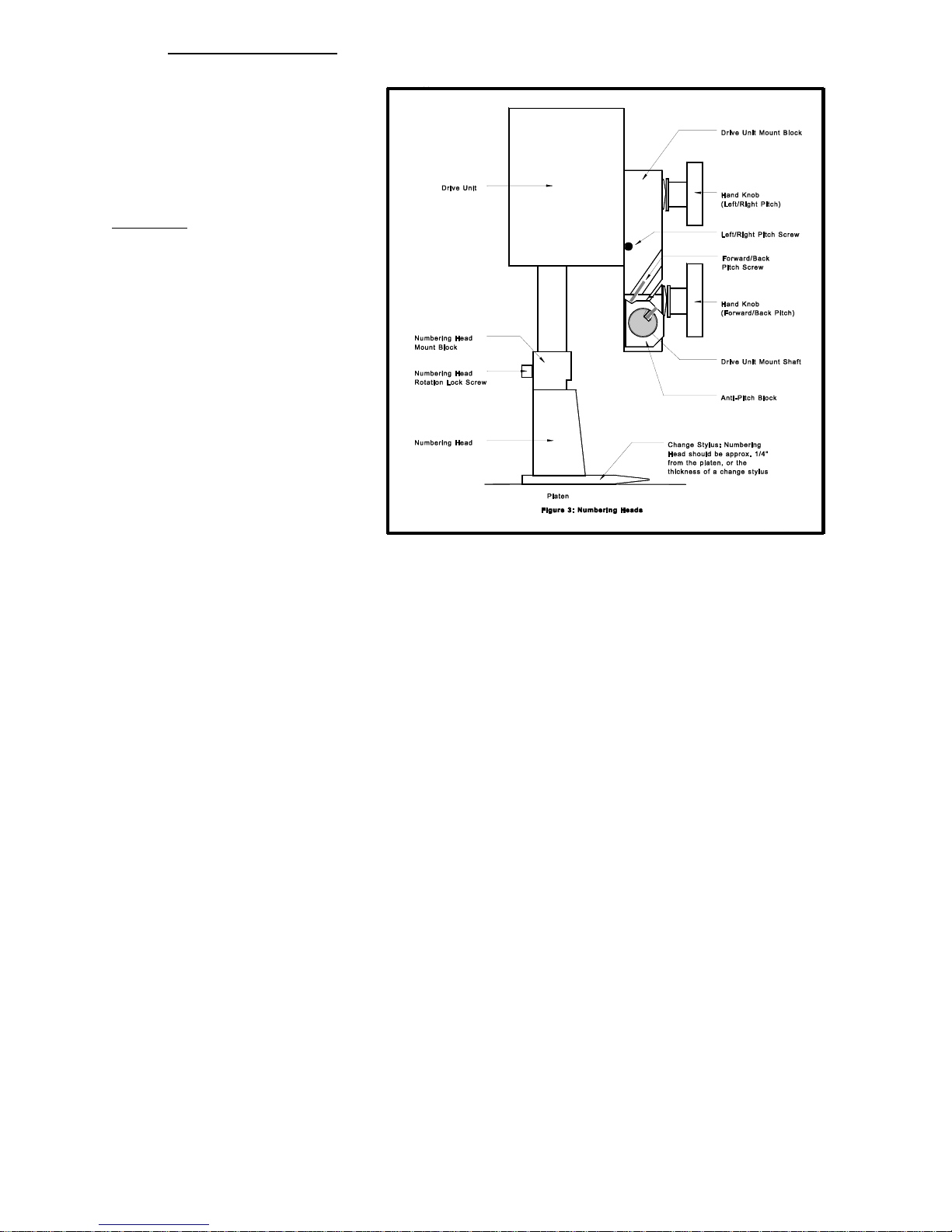
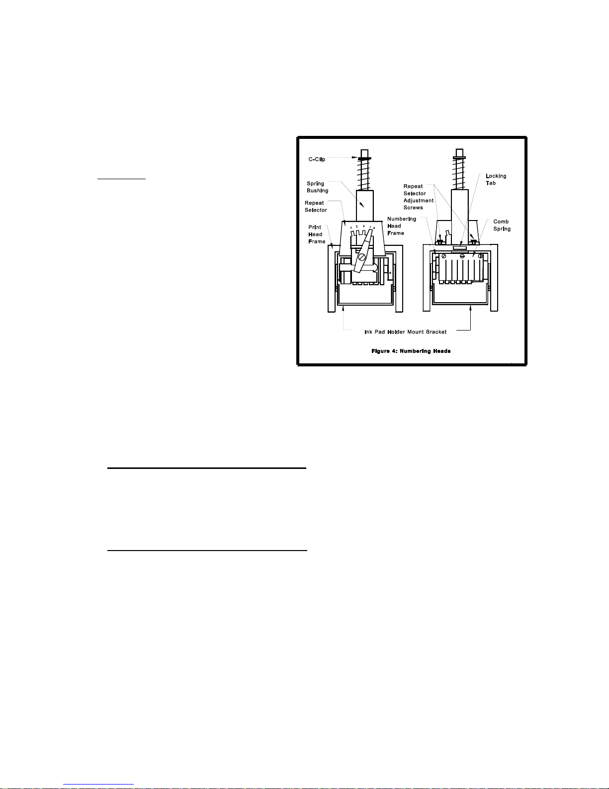
2.3 Numbering Heads
The numbering heads
are already secured to the
drive unit by two screws
through the numbering head
mount block as shown in
Figure 3. The drive unit is
then mounted to the drive
unit mount block using the
hand knob provided. While
installing the drive unit,
make sure the screw cap on
the back of the drive unit fits
in the cavity on the drive unit
mount block so that the
rubber plug provides some
pressure against the screw
cap. To do this, you may
have to back out the left/right
pitch screw. Plug in the cord
from the drive unit into the appropriate receptacle on the non-operator side cover
(closest head to the closest receptacle). If your machine is equipped with more than
one head, by convention, the numbering head and drive unit closest to the operator
control panel will be referred to as head #1(H1) and the other will be head #2 (H2).
The height of the numbering head has been factory set and it is critical to the
proper performance of the drive unit and numbering head. This distance is
approximately 3" or the thickness of a numbering wheel change stylus. However,
the numbering head must be levelled to ensure that the numbering wheels strikes
the sheet square to provide a quality inked impression and a flat crash impression
on carbonless sets. This will be discussed later (Section 4.11).
The numbering heads can operate through 360Ε. This is done by loosening
the numbering head rotation screw (using the large hexdriver supplied) located on
the front of the numbering head mount block. Once the screw is loose, the head is
free to rotate. Tighten the screw once the desired position is achieved in order to
prevent any movement during machine operation.
The standard numbering head is
digits with 2 drop wheels. The numbering head employs a pre-inked pad, which
can be purchased in red or black. These inkpads will supply you with
approximately 15,000 impressions. Uninked pads may be purchased if a different
colour is required (Note: any ink used must be a non-metal corrosive one, labelled
numbering machine ink).
3
/16" (4.5mm) Gothic style, reverse order, 6
Page 5
The numbering head comes standard with six numbering wheels (a seventh
numbering wheel is optional), the last two of which are drop wheels (this will be
discussed later). The first 5 digits may be activated only. The 6th (or 7th) digit
must be changed manually. Also available are letter prefix wheels (A-J;K-R;S-Z)
and a µ prefix wheel. Modifications are possible with new numbering head orders
or by special order.
The numbering heads also have
a repeat function. The repeat selector
(see
Figure 4) allows a number to be
repeated from one to four times. By
leaving the repeat selector in the "0"
position, the number will not change
when the head returns to the print
position. Using the "0" position
prevents you from having to re-set the
starting number when you are
programming a new job (this will be
discussed later). Position "1" changes
the number consecutively with each
stroke and positions "2", "3" and "4"
repeat the number 2, 3 or 4 times
respectively. The repeat functions are achieved by a mechanical ratchet action in
the numbering head. When trying to use these functions, you may have to cycle the
numbering head manually in order to match the number of repeats on a page to the
number positions on a page.
2.4
Optional Conveyor Outfeed Plate
The conveyor outfeed plate sits in the machine in the same fashion as the exit tray. Make sure that the spur
gears mesh and do not force the conveyor outfeed plate into position. The pile tray is mounted on the end of the
conveyor outfeed plate, with two Phillips screws and acts as a backstop for the finished stock.
2.5
Additional Switches and Controls
The main on/off switch is located under the feed tray beside the main
fuseholder and power cord.
On the left-hand side of the operating keyboard, there are two potentiometer
knobs that control the crash strength of the numbering head, known as Impression
Controls and can be adjusted to best suit the requirements of the job. For example,
you may require stronger crash numbering for carbonless sets than for single sheet
bond paper. This adjustment can be done while the machine is stopped or running.
Page 6
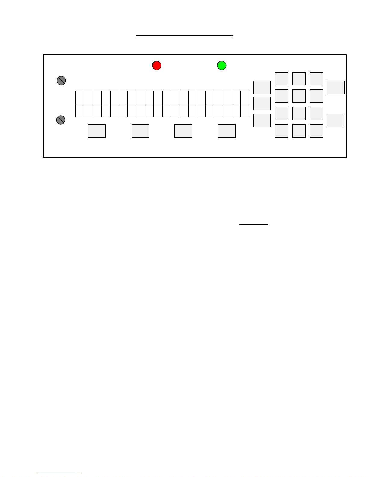
3.0
N
Operating Keyboard
IMPRESSION 1
O FUNCTION
IMPRESSION 2
G R A P H I C W H
C A N A D A
<<<
PERF SHIELD (RED) PHOTOCELL (GRN)
FLASHES IF RAM ERROR FLASHES IF LCD ERROR
>>>
I Z A R D
F1
F2
SETUP
SETUP
BAT
REP
ESC
2 31
64
5
97 8
0
ACC
The operating keyboard is comprised of a two line LCD display, various
buttons and two Impression Controls which consist of two potentiometer knobs
that control the crash strength of the numbering head, and can be adjusted to best
suit the requirements of the job. For example, you may require stronger crash
numbering for carbonless sets than for single sheet bond paper. This adjustment
can be done while the machine is stopped or running (see
Figure 5).
The four buttons under the LCD display will perform whatever function is
shown directly above them on the bottom line of the LCD display. They may not
always be active (this is the case for the other buttons as well). Three specific
function buttons (SET UP, BAT, REP) are situated beside the display. A
numeric keypad, an ‘ESC’ (escape), ‘ACC’ (accept), ‘START’ and ‘STOP’
button rounds out the rest of the keyboard. The 'ESC' button can be used at almost
any time (except during actual running) in order to return to the previously viewed
menu. The functions of the rest of the buttons will be discussed later in this
section.
Once you have plugged the machine in, turn the on/off switch to the 'on'
position. The microprocessor does an internal system check and the above will
flash on the screen.
START
STOP
Page 7
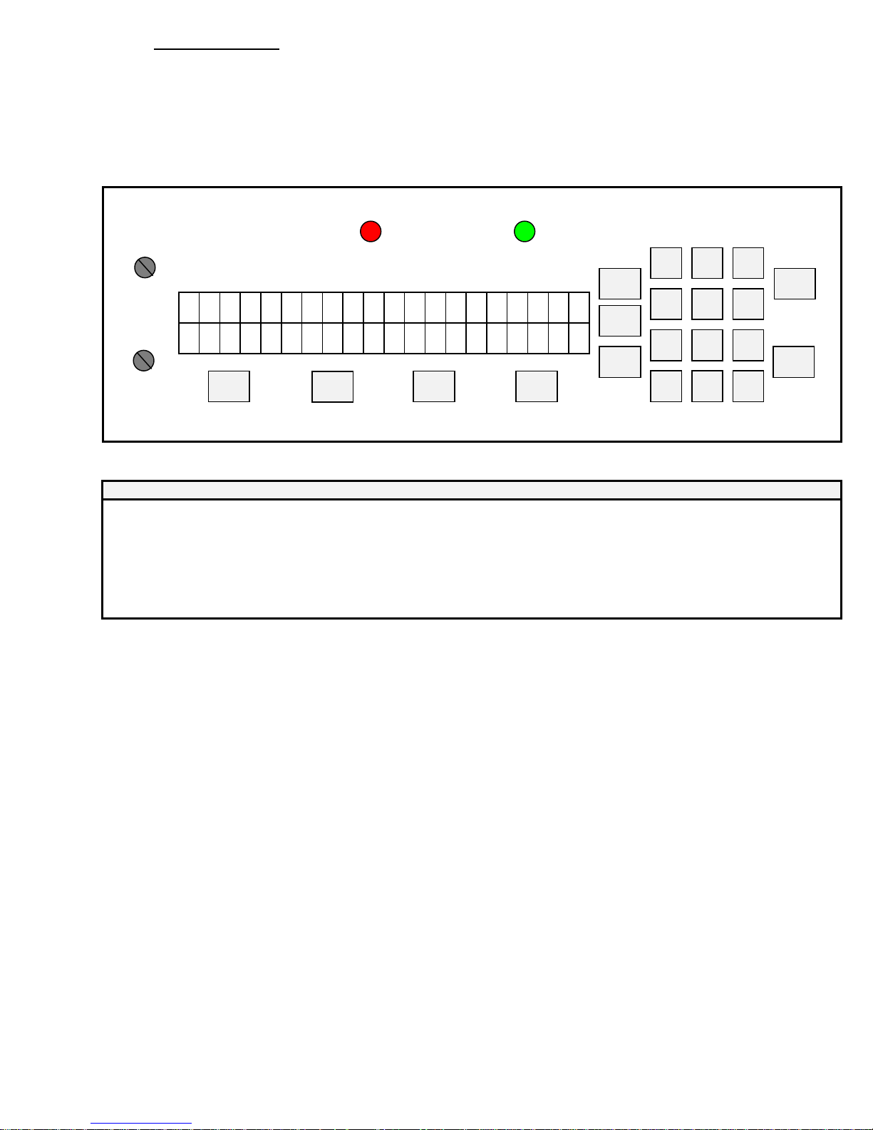
3.1 Running a Job
The Idle Mode is displayed below. From this menu, you can change the
motor speed, modify your paper count and select your program.
In this menu you can also enter the Batch size (see 3.5)
DISPLAY:
PERF SHIELD (RED) PHOTOCELL (GRN)
IMPRESSION 1
IMPRESSION 2
s s s s s s P G M
↓
<<<
ON = PERF SHIELD OPEN ON = NO PAPER
x x x c c
↑
>>>
F1
DISPLAY FUNCTIONS:
DISPLAY
ssssss = motor speed bar graph
PGMxxx = solenoid program in RAM
cccccc = paper count
↓ = decrement motor speed
↑ = increment motor speed
-1 = decrement paper count
aaa = CLR -> clear paper count normally; aaa = BAT -> Enter Mode - Set Batch Size when batch mode is enabled
2 31
SETUP
SETUP
64
c c
c
a
aca 1-
F2
BAT
REP
ESC
5
97 8
0
ACC
START
STOP
The <<</>>> will adjust the motor speed, F1 will decrement the paper count, F2 will
clear the paper count but if it is already at 0 it will send you to the Batch mode (Section
3.5). SETUP will select a program (Section 3.3) and START will begin the job. You will
now be in the Run Mode.
When the machine is first turned on, it defaults to Program 01 (PGM001),
which is shown on the menu. Pressing the 'START' button will automatically
begin Program 01. The main operating menu will change as the machine is
running.
Page 8
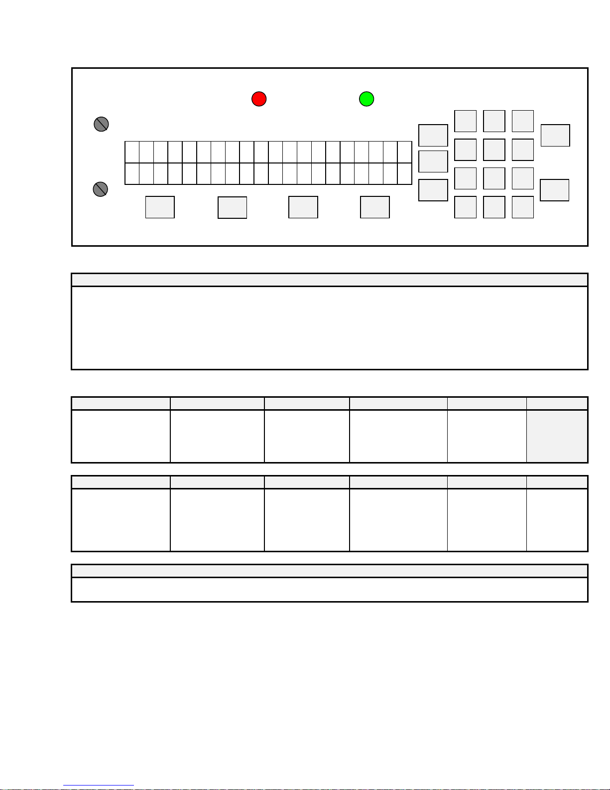
The Run Mode menu looks like this:
(
)
DISPLAY:
PERF SHIELD (RED) PHOTOCELL (GRN)
IMPRESSION 1
ON = PERF SHIELD OPEN
WILL EXIT TO Mode -Idle
SOL CH1 ADJUST
PULSE WIDTH
IMPRESSION 2
SOL CH2 ADJUST
PULSE WIDTH
s s s s s s P G M
↓
<<<
↑
>>>
x x x c c
F1
DISPLAY FUNCTIONS:
DISPLAY
ssssss = motor speed bar graph
PGMxxx = solenoid program in RAM
cccccc = paper count
↓ = decrement motor speed
↑ = increment motor speed
HALT = motor emergency stop, exit to Mode - Idle
aaa = CLR -> clear paper count normally; aaa = BAT -> Display current batch size when batch mode is enabled
KEYPAD FUNCTIONS:
<<< >>> F1 F2 STOP START
DECREMENT MOTOR SPEED INCREMENT MOTOR SPEED MOTOR EMERGENCY
STOP
Exit to Mode - Idle
ACC ESC SETUP BAT REP
MOTOR EMERGENCY STOP
Exit to Mode - Idle
MOTOR EMERGENCY STOP
Exit to Mode - Idle
MOTOR EMERGENCY
STOP
Exit to Mode - Idle
DIG 0-9
MOTOR EMERGENCY STOP
Exit to Mode - Idle
ON = NO PAPER
c c
c
a
aca TLAH
F2
IF BATCH SIZE IS ZERO
CLEAR PAPER COUNT
ELSE:
DISPLAY BATCH SIZE
IF BATCH SIZE IS ZERO
MOTOR EMERGENCY STOP
Exit to Mode - Idle
ELSE:
DISPLAY BATCH SIZE
SETUP
SETUP
BAT
REP
2 31
5
ESC
Complete numbering
Eject current sheet
Stop motor
Exit to Mode - Idle
MOTOR EMERGENCY
STOP
Exit to Mode - Idle
0
64
97 8
ACC
START
STOP
Page 9
 Loading...