

Page 1

Graphic Products, Inc.
DuraLabel
THERMAL TRANSFER PRINTER
®
PRO
PRINTER MANUAL
v.1.2
Graphic Products, Inc.
1-800-788-5572
www.DuraLabel.com
www.GraphicProducts.com
E-mail: [email protected]
Copyright 2007, 2008, 2009 Graphic Products, Inc.
Page 2

Contents
1. Introduction ............................................................................................
2. Getting Started .......................................................................................
2.1 Unpacking and Inspection ..............................................................
2.2 Equipment Checklist .......................................................................
2.3 Printer Parts .....................................................................................
3. Setup ......................................................................................................
3.1 Setting Up the Printer ......................................................................
3.2 Loading the Ribbon .........................................................................
3.3 Loading Label Stock .......................................................................
3.4 Cutter Module Installation (Option) ...............................................
3.5 Instructions to Top Cover Operation ............................................
4. Power on Utilities ..................................................................................
4.1 Ribbon Sensor Calibration .............................................................
4.2 Gap/Black Mark Calibration ...........................................................
4.3 Initialization .....................................................................................
5. Maintenance ..........................................................................................
5.1 Cleaning ...........................................................................................
6. Troubleshooting ....................................................................................
6.1 LED Status .......................................................................................
6.2 Print Quality .....................................................................................
7. Specifications ........................................................................................
7.1 Printer Specifications .....................................................................
7.2 Label Stock Specifications .............................................................
7.3 Ribbon Specifications .....................................................................
8. LED and Button Operation ...................................................................
8.1 LED ...................................................................................................
8.2 Button Operation .............................................................................
1
1
1
1
2
3
3
3
5
7
10
12
12
12
15
16
16
17
17
18
19
19
20
20
21
21
22
9. Warranty .................................................................................................
23
Page 3

1. Introduction
Thank you for purchasing the DuraLabel® PRO Thermal Transfer Printer. Although
the printer takes only a small amount of space, it delivers reliable, superior
performance.
This printer provides thermal transfer printing at user selectable speeds of: 2.0, 3.0,
4.0 or 5.0 ips. It accepts continuous and die-cut labels for thermal transfer printing.
All common bar code formats are available. Fonts and bar codes can be printed in 4
directions, 8 different alphanumeric bitmap fonts and a built-in true type font
capability.
2. Getting Started
2.1 Unpacking and Inspection
This printer has been specially packaged to withstand damage during shipping.
However, please carefully inspect the packaging and printer upon receipt. Please
retain the packaging materials in case you need to reship the printer.
2.2 Equipment Checklist
Installation CD
Label spindle (1 inch diameter core)
Fixing Tabs (2 pcs.)
Ribbon supply/rewind spindles (2 pcs.)
AC Adaptor
USB Interface
Parallel Interface
Quick start guide
If any parts are missing, please contact your Customer Sales Representative.
Page 4

2.3 Printer Parts
Clear Window
Ribbon Access Window
LED Indicator
Fig. 1 Top front view
Feed Button
Printer Top Cover
Top Cover Release Lever
1. USB Interface
2. Centronics Interface
3. RS-232 DB-9 Interface
4. Power Jack
5. Power Switch
1 2 3 4 5
Fig. 2 Rear view
2
Page 5
3. Setup
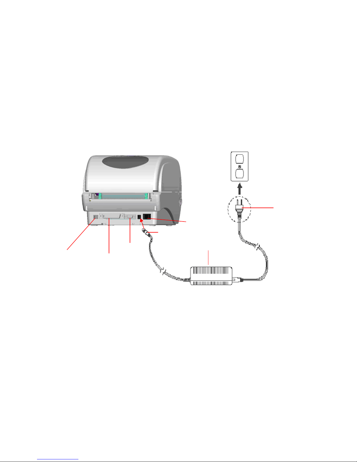
3.1 Setting Up the Printer
1. Place the printer on a flat, secure surface.
2. Make sure the power switch is off.
3. Connect the printer to the computer with the Centronics or USB cable.
4. Plug the power cord into the power supply connector at the rear of the printer,
then plug the power cord into a properly grounded receptacle.
Plug
USB
Power Cable
RS-232
Centonics
Power Switch
Power Supply
Fig. 3 Attach power supply to printer
3.2 Loading the Ribbon
The printer automatically detects if a ribbon is installed after power on and will switch
to thermal transfer or direct thermal printing mode. If printer does not detect the
ribbon, the motor that drives the ribbon rewind spindle will be turned off. In the case
that a ribbon is installed, but the ribbon rewind spindle does not turn, please refer to
the ribbon calibration procedure in section 4.1 to calibrate the ribbon sensor
sensitivity. Also check that the print driver is set to Thermal Transfer on the Stock tab
of printer preferences. (See page 25 of the User’s Guide).
3
Page 6
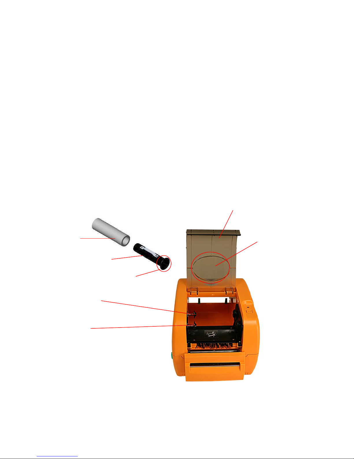
Make sure both the ribbon access window and the printer top cover are closed when
powering up the printer.
1. Push down on the ribbon access window to unlock and open the ribbon cover.
2. Place a paper core onto the ribbon rewind spindle.
3. Mount the ribbon rewind paper core on the front hubs.
4. Install a ribbon on the ribbon supply spindle.
5. Mount the ribbon supply spindle on the rear hubs.
6. Open the top cover of the printer.
7. Pull the ribbon from the ribbon supply roll under the print head and attach it to
the ribbon rewind paper core. (See diagram inside back of printer)
8. Rotate the ribbon rewind paper core by turning the spindle flange with your
thumb until the ribbon rewind core is completely wrapped with the black
section of the ribbon.
9. Close the top printer cover and ribbon cover.
Ribbon Cover
Paper Core
Ribbon Spindle
Rear Hub
Front Hub
Ribbon Access
Window
Flange of Ribbon
Spindle
Fig.4 Ribbon installation (I)
4
Page 7
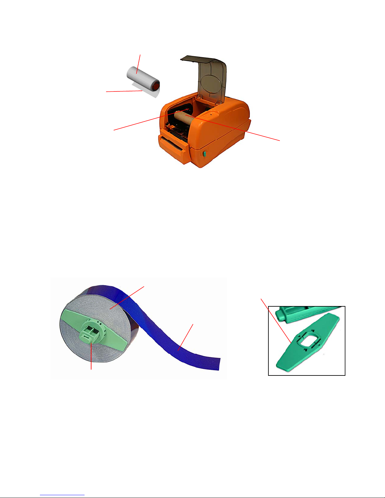
Ribbon Supply Spindle
Ribbon
Leader
Rear Hub
Fig. 5 Ribbon installation (II)
Ribbon Rewind
Spindle with
Paper Core
3.3 Loading Label Stock
The ribbon and various print media for the DuraLabel® PRO have been optimized for
compatibility and print quality. Only authorized supplies from Graphic Products will
print correctly in the DuraLabel® PRO.
1. Insert a 1” label spindle into a roll of label stock.
Label Stock
Printing Side
Face Up
" Label Spindle
1
Fig. 6 Label roll installation (I)
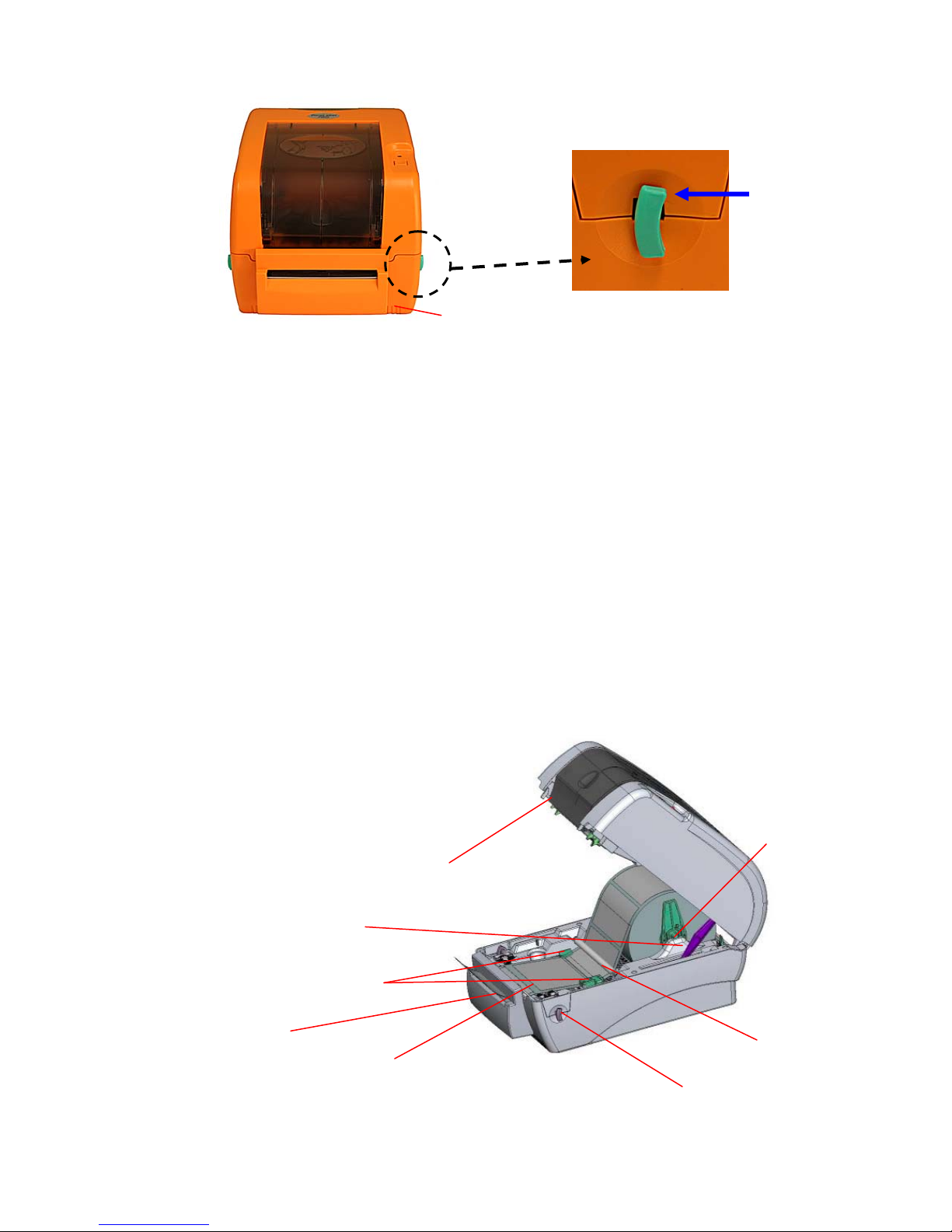
2. Open the printer’s top cover by releasing the turquoise levers located on each side
of the printer and lifting the top cover. A top cover support at the rear of the printer
will hold the printer top cover open.
Fixed Tab
5
Page 8
T
Pull
release
Lower Cover
lever
forward
Fig. 7 Pull the lever to open the cover
3. Place a roll of label stock onto the center of the paper roll mount.
4. Feed the label stock, printing side face up, under the Teflon bar and the label
guides and pass over the platen, then feed through the cutter.
5. Adjust the green center-biased label guides to slightly touch the edges of the
label stock.
6. To close the printer top cover, lift the cover until it stops then use both hands to close
the cover gently. Close the printer top cover slowly and make sure the cover locks
securely.
Note:
1. Make sure your hands are not inside the printer when closing the top cover.
2. Do not let the top cover free fall.
3. Failure to securely close and lock the cover will result in poor print quality or a
flashing LED and the inability
to print.
Label Roll Mount
Printer Top Cover
Support Bar
Adjustable
Label Guides
Cutter
Platen Roller
Fig. 8 Label installation (II)
eflon Bar
Top Cover
Release Lever
6
Page 9
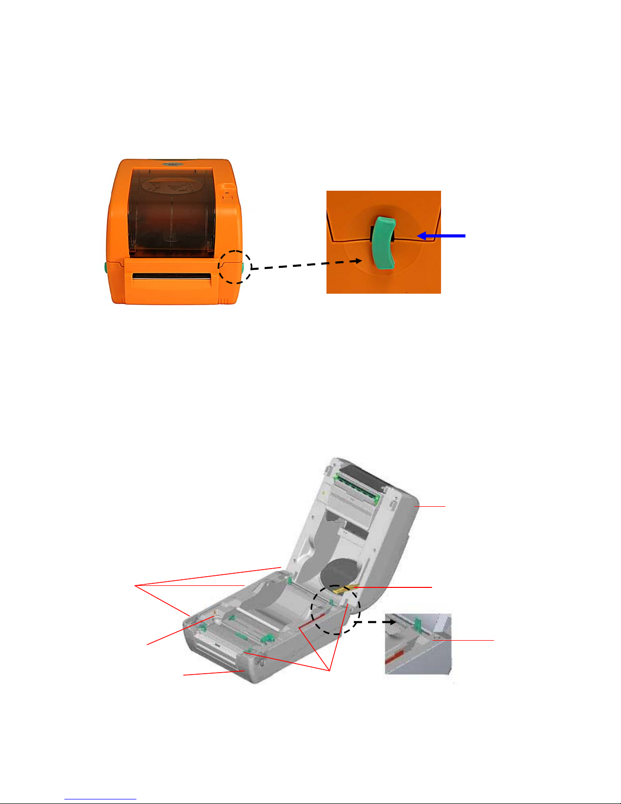
3.4 Cutter Module Installation (Option)
1. Pull the top cover release levers forward to open the top cover.
2. Remove the front panel from the lower cover.
Fig. 22 Pull the lever to open the cover
Pull
release
lever
forward
3. Open the top cover. While supporting the cover with your left hand, push back
firmly on the base of the top cover support. The support will pop out of its’
normal position to allow the cover to be opened further.
4. Use a screwdriver to unscrew 6 screws on the lower inner cover.
Screws
Lower Inner Cover
Lower Cover
Top Cover
Top Cover Support
Flute
Screws
Fig. 23 Remove 6 screws from lower inner cover
7
Page 10
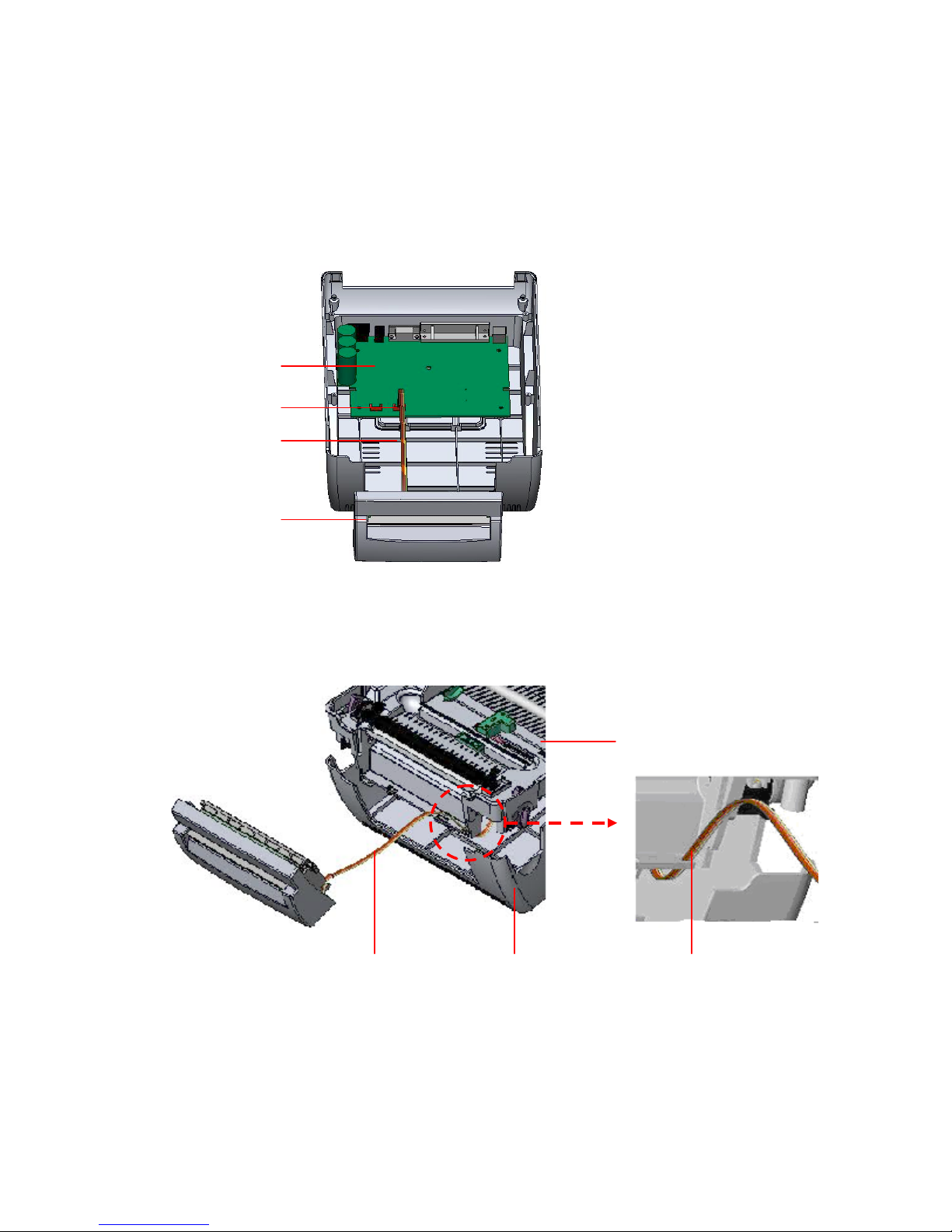
5. Place the printer upside down and unscrew the two screws of the hinge
holder on the lower cover. Unscrew the screw of the memory card cover.
6. Use both thumbs to hold the lower cover and index fingers to lift up the top
cover open levers to separate the lower inner cover and the lower cover.
7. Connect the cutter module cable to the 4-pin socket on printer PCB.
PCB
4-pin Socket
Cutter Cable
Cutter
Fig. 24 Cutter module installation
8. Arrange the cable through the bezel.
Lower Inner Cover
Cutter Cable
Bezel Lower Cover
Fig. 25 Cutter module cable arrangement
8
Page 11
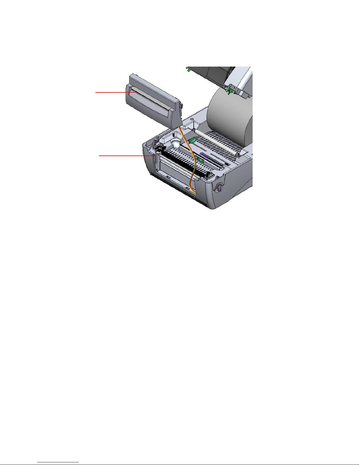
9. Place the lower inner cover back onto the lower cover.
10. Install the cutter into the niches of the printer.
Cutter
Niche
Fig. 26 Cutter module installation
11. Use a screwdriver to screw 6 screws on the lower inner cover.
12. Place top cover support back into the flute and push forward.
13. Close the cover slowly.
9
Page 12

3.5 Instructions to Top Cover Operation
Please take care when opening or closing the printer’s top cover by carefully following
these instructions.
To Open:
1. When facing the front of the printer, pull the cover release levers on both sides of
printer towards you.
2. Lift the top cover slowly.
There are two stop positions for the top cover. Position 1 and 2 are indicated on the
label below.
Note: To hold the cover open at position 1, you must lift the cover higher than the
stopping point at position 1 and gently lower the cover to stopping point 1.
Do not let the cover free fall!
3. Fully open the top cover and gently lower it to stop position 2.
Fig. 1 Top cover support is fixed at position 2
10
Page 13
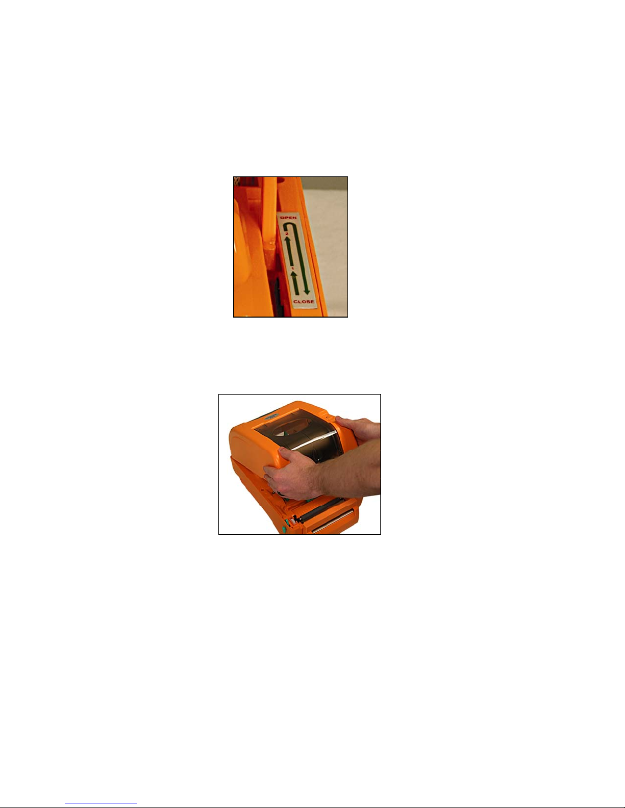
4. To close the cover, lift the top cover all the way up then lower the top cover gently.
Use both hands to gently push down the top cover to close it and make sure the
cover is latched on both sides.
Note: Do not place your hands between top cover and lower cover when
closing the top cover!
Fig. 2 Top cover is fully open and ready to close
Fig. 3 Use both hands to close the top cover
5. Do not force the cover! If the cover does not close with gentle pressure, lift the
cover as far as it will go and try to gently close it again.
11
Page 14

4. Power on Utilities
There are three power-on utilities to set up and test printer hardware. These
utilities are activated by pressing FEED button and by turning on the printer power
simultaneously. The utilities are listed as below:
1. Ribbon sensor calibration
2. Gap or black mark sensor calibration
3. Self-test
4. Printer initialization
4.1 Ribbon Sensor Calibration
Please follow the steps below to calibrate the ribbon sensor.
1. Turn off the power and wait 5 seconds.
2. Press and hold the FEED button then turn on printer power.
3. Release the button while the LED blinks red.
The LED color will blink in the following pattern:
Orange red (5 blinks) orange (5 blinks) green (5 blinks) solid green
4.2 Gap/Black Mark Calibration
Gap/black mark sensor sensitivity should be calibrated at the following
conditions:
1. The printer is brand new
2. The die-cut label stock has been changed
3. Printer initialization
Calibration of the gap or black mark sensor depends on the sensor setting in the
last print job. Please follow the steps below to calibrate the sensor.
1. Turn off the power and wait 5 seconds.
2. Press and hold the FEED button then turn on printer power.
3. Release the button while the LED blinks orange
The LED color will blink in the following pattern:
Orange red (5 blinks) orange (5 blinks) green (5 blinks) solid green
12
Page 15
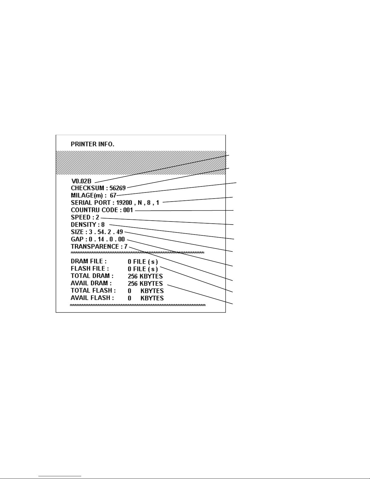
While calibrating the gap/black mark sensor, the printer will measure the label
length, print the internal configuration and then enter the dump mode.
A self-test printout can be used to check if there is any dot damage on the heater
element, printer configurations or available memory space.
Turn the power off, wait 5 seconds and turn it back on to resume normal printing.
Print head check pattern
Firmware version
Firmware checksum
Printed mileage (meter)
Serial port configuration
Country code
Print speed (inch/sec)
Print darkness
Label size (inch)
Gap distance (inch)
Gap/black mark sensor sensitivity
Number of download files
Total & available memory space
Fig. 29 Self-test printout
13
Page 16
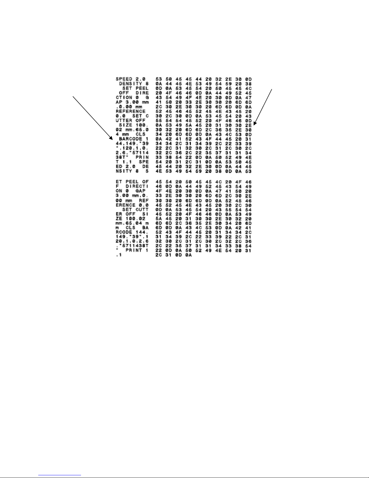
The printer will enter dump mode after printing the printer configuration. In the dump
mode, all characters will be printed in two columns as follows:
ASCII Data
Hex decimal
data related to
left column of
ASCII data
Fig. 30 Dump mode printout
The left side characters are received from your system and right side data are the
corresponding hexadecimal value of the characters. It allows users or engineers to
verify and debug the program. Turn off and on the power switch to reset the printer
for normal printing.
14
Page 17

4.3 Initialization
Printer initialization is used to clear DRAM and restore printer settings to
defaults. The only one exception is ribbon sensitivity, which will not be restored
to default.
Printer initialization is activated by the following procedures.
1. Turn off printer power and wait 5 seconds.
2. Press the FEED button and then turn on power. The LED will blink five times
per color (red, orange, green).
3. Release the FEED button when the LED blinks green.
The LED color will be changed as following pattern:
Orange red (5 blinks) orange (5 blinks) green (5 blinks) solid green
4. Printer configuration will be restored to defaults as below after initialization.
Parameter Default setting
Speed 3 inches per second
Density 7
Label Width 4.25 in. (108.0 mm)
Label Height 2.5 in. (63.4 mm)
Sensor Type Gap sensor
Gap Setting 0.12 in. (3.0 mm)
Print Direction 0
Reference Point 0,0 (upper left corner)
Offset 0
Tear Mode On
Peel off Mode Off
Cutter Mode Off
9600 bps, none parity, 8 data bits, 1 stop
Serial Port Settings
Code Page 850
Country Code 001
Clear Flash Memory
bit
No
15
Page 18

5. Maintenance
t
5.1 Cleaning
Use one or more of the following supplies that meets your needs:
Cleaning pens
Cleaning swabs
Lint-free cloth
Always unplug the printer when performing cleaning!
The cleaning process is described as follows.
Printer Part
Printer Head
Platen Roller
Exterior
Interior
Allow
cleaning swab to wipe the print elements.
Rotate the platen roller and wipe it thoroughly
with a cleaning swab or lint-free cloth.
Wipe it with water-dampened cloth.
Brush or air blow.
he print head to cool for one minute. Use a
Method
16
Page 19
6. Troubleshooting
This section provides possible solutions to common printing, operating, and LED
status problems you may encounter.
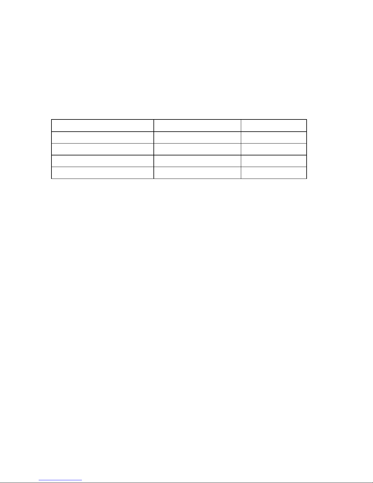
6.1 LED Status
LED Status / Color Printer Status Solution Number
Off Off 1
Solid Green On 2
Blinking Green Pause 3
Blinking Red Stopped 4
1. No power.
Turn on the power switch.
Check if the green LED is lit on power supply. If it is not lit, the power
supply is broken.
Check both power connection from the power cord to the power supply
and from the power supply to the printer power jack.
2. The printer is on and ready to use.
No action necessary.
3. The printer is paused.
Press the feed button to resume printing.
4. The out of label or ribbon or the printer setting is not correct
Out of label or ribbon
Load a roll of label stock as instructed in Loading the Label Stock,
(Section 3.3) then press the feed button to resume printing.
Load a roll of ribbon as instructed in Loading the Ribbon, (Section 3.2)
then press the feed button to resume printing.
Printer setting is not correct
Initialize the printer by following the instructions in “Power on Utility”.
17
Page 20

6.2 Print Quality
Continuous feeding labels
The printer setting may go wrong. Please do the Initialization and Gap/Black
Mark Calibration. (See section 4.2 and pages 25-26 of the User’s Guide).
No print on the label
Is the label or ribbon loaded correctly? Follow the instructions in
Loading the Label Stock (See section 3.3) or Loading the Ribbon.
Has the ribbon run out? Follow the instructions in Loading the Ribbon
(See section 3.2).
Poor print quality
Top cover is not closed properly. Close the top cover completely and make sure the
right side and left side levers are latched to top cover properly.
Clean the thermal print head with a cleaning swab.
Adjust the print density setting and or speed setting.
(See page 27 of the User’s Guide).
18
Page 21

7. Specifications
7.1 Printer Specifications
Item DL PRO
Mechanism
Resolution 203 dpi.
Max. Print Width 4 in.
Max. Print Length 60 in.
Ribbon Capacity 984 ft. with 1 in. core
Printing Speed 2, 3, 4 and 5 ips.
Printing Method Direct thermal and thermal transfer printing
Enclosure
Structure Double-walled plastic.
Dimension Standard Model: 12.4 in.(L) x 8.4 in.(W) x 7.4 in.(H)
Operation Panel One push switch, and one indicator LED (Green,
Orange, Red colors).
Hardware
Sensor Transmissive sensor (offset 0.25 in. from liner edge).
Reflective sensor (position adjustable). Head open micro
switch. Ribbon end sensor
Memory Interface 1M byte Flash memory 2M bytes DRAM
RS-232C (max baud rate, 19,200 bps).
USB: V1.1
Centronics
Power AC input: 100-240V universal auto switching power
supply. DC output: 24V 3.75A
Firmware
Font Type 8 alpha-numeric bitmap fonts, and 1 true type font
Rotation 0, 90,180 and 270 degrees
Barcode Format 1D Bar code
ITF-14, EAN-14.
Code 39, Code 93, Code 128UCC, Code128 subsets
A.B.C, Codabar, Interleave 2 of 5, EAN-8, EAN-13,
EAN-128, UPC-A, UPC-E, EAN and UPC2(5) digits add-on,
MSI, PLESSEY, POSTNET, ChinaPOST,
19
Page 22
Command Set TSPL2
2D Bar code
PDF-417, Maxicode, and DataMatrix, QR CODE
Environment
Operation
Relative Humidity: 25% ~ 85% (Non Condensing)
Storage
Relative Humidity: 10% ~ 90% (Non Condensing)
Temperature: 41°F ~ 104°F (5 ~ 40).
Temperature: -40°F ~ 140°F (-40 ~ 60).
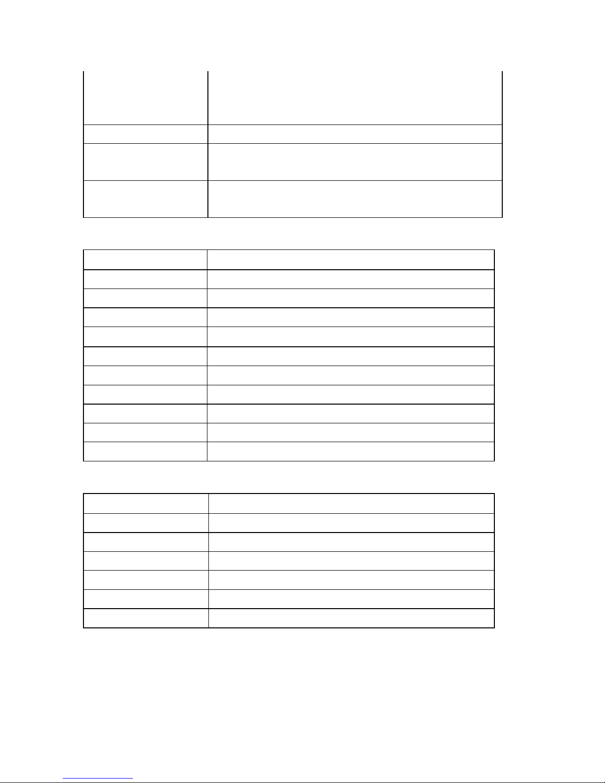
7.2 Label Stock Specifications
Item Specification
Type Label (Continuous & Die-cut)
Wound Type Outside wound
Width 0.5 in. – 4 in.
Length 0.4 in. – 60 in.
Thickness
Roll Diameter 5 in.
Roll Core Diameter 1 in.
Gap Height 0.08 in. min.
2.3 mil. ~ 7.4 mil.
Black Mark Height 0.08 in. min.
Black Mark Width 0.31 in. min.
7.3 Ribbon Specifications
Item Specification
Type Wax, Wax / Resin, Resin
Core Diameter 1 in.
Width Max 110mm
Capacity 300m with 1 in. core
Wound Type Outside wound
Ribbon End Clear or silver end tape
20
Page 23
8. LED and Button Operation
t
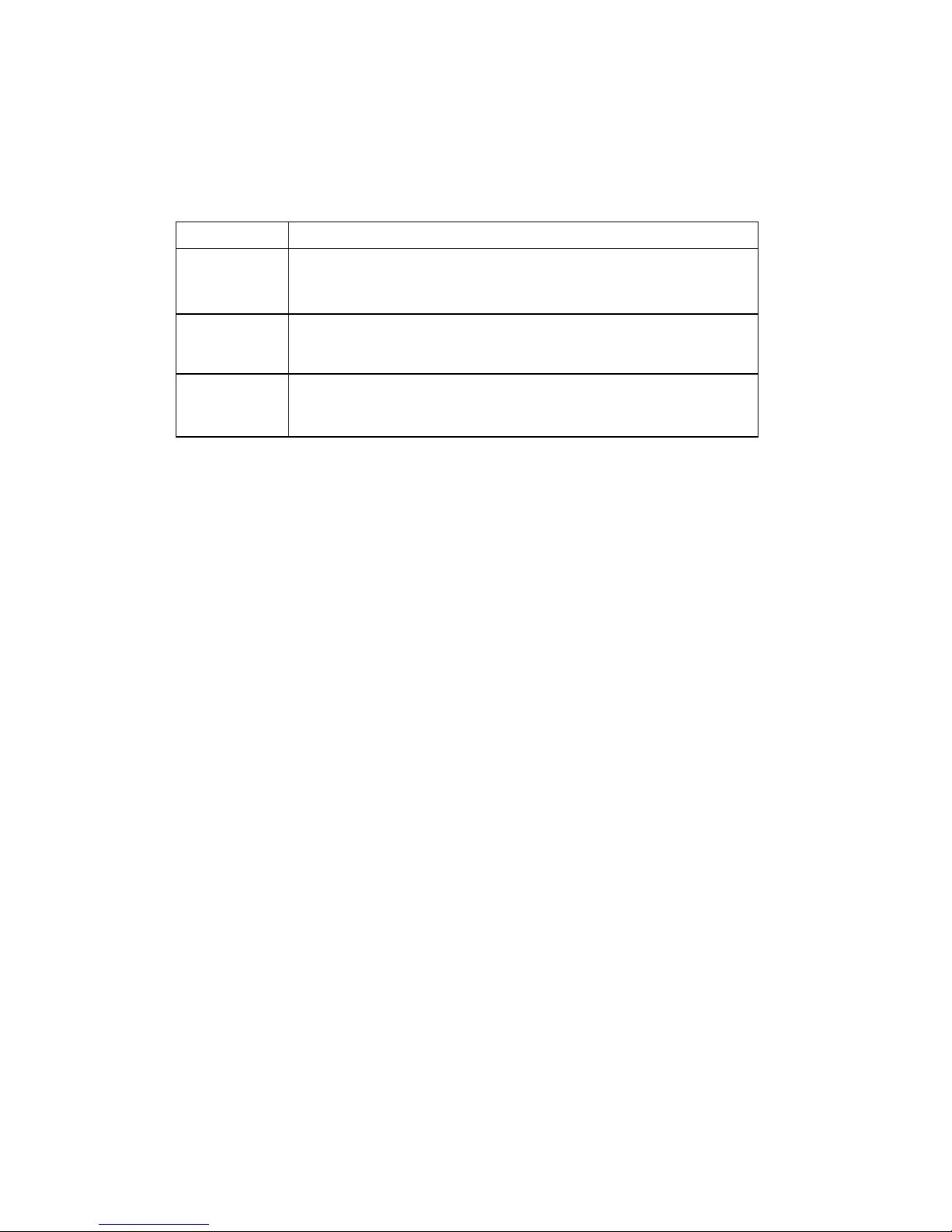
8.1 LED
LED Color Description
Green
Orange This shows
Red
This shows that the power is on and the device is
ready to use.
hat the system is detecting the paper
and ribbon status
This shows a printing error, such as paper empty,
ribbon empty, or cover opened etc.
21
Page 24

8.2 Button Operation
Feed
Press the button when the LED is green.
It feeds the label to the beginning of the next label.
Pause
Ribbon Sensor
Calibration
Gap/Black Mark Sensor
Calibration, Label
Length Measurement,
Self Test and Enter
Dump Mode
Press the feed button during printing.
The printing job is suspended.
Turn off the power switch and wait 5 seconds.
Press the button while turning on the power switch.
Release the button when LED blinks red.
It will calibrate the ribbon sensor sensitivity.
Turn off the power switch and wait 5 seconds.
Hold down the button while turning on the power switch.
Release the button when LED blinks orange.
The LED color will flash as follows:
Orangered (5 blinks)orange (5 blinks)
green (5 blinks)solid green.
It calibrates the sensor, measures the label length
and prints internal settings then enters the dump mode.
Printer Initialization
Turn off the power switch and wait 5 seconds.
Hold down the button while turning on the power switch.
Release the button when LED turns green after 5
orange blinks.
The LED color will flash as follows:
orangered (5 blinks)orange (5 blinks)
green (5 blinks)solid green.
Always do gap/black mark sensor calibration after
printer initialization when printing on die-cut labels.
22
Page 25

9. Warranty
The Graphic Products DuraLabel PRO is warranted to be free from defects in
materials or workmanship for a period of two years from the date of purchase with
the following exception: The DuraLabel PRO print head is warranted to be free from
defects in materials and workmanship for a period of one year from the date of
purchase. Within this period, Graphic Products, Inc. will, at its sole option, repair or
replace any components which fail in normal use. Such repairs or replacement will
be made at no charge to the customer for parts or labor, provided that the customer
shall be responsible for any transportation cost. This warranty does not cover
equipment or parts which have been misused, altered, neglected, carelessly handled,
used for purpose other than those for which the printer was manufactured or
damages resulting from unauthorized service.
Note: Repairs have a 90 day warranty. If the unit sent in is still under its original
warranty, then the new warranty is 90 days or to the end of the original warranty,
depending upon which is longer.
The Warranties and remedies contained herein are exclusive and in lieu of all other
warranties whether express, implied or statutory, including any liability arising under
any warranty of merchantability or fitness for a particular purpose, statutory or
otherwise. This warranty gives you specific legal rights, which may vary from state to
state.
In no event shall Graphic Products be liable for any incidental, special, indirect or
consequential damages, whether resulting from the use, misuse or inability to use
the product for any reason including defect. Some states do not allow the exclusion
of incidental or consequential damages, so the above limitation may not apply in all
areas.
Graphic Products retains the exclusive right within all warranty periods to repair,
replace the product or offer a full refund of the purchase price at its sole discretion.
Such remedy shall be your sole and exclusive remedy for any breach of warranty.
For further service information, please contact your Graphic Products representative
at 1-800-788-5572 or www.graphicproducts.com.
23
 Loading...