

Page 1
1-800-788-5572
International: +1 503-644-5572
[email protected]
www.GraphicProducts.com
www.DuraLabel.com
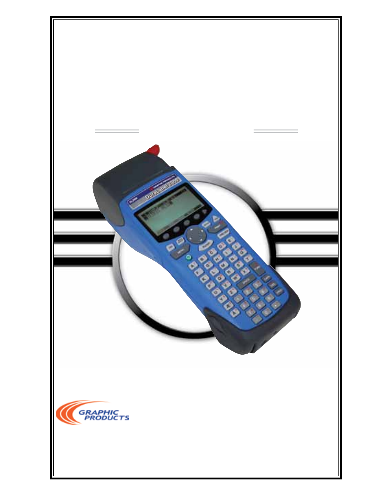
User’s Guide
DuraLabel
®
2000
Page 2

1. INTRODUCTION ..................................................................................................1
Welcome ...........................................................................................................1
Safety Precautions ...........................................................................................1
DeviceSpecications .......................................................................................2
2. GETTING STARTED .............................................................................................3
Unpacking & Inspection ...................................................................................3
Equipment Checklist ........................................................................................3
3. The BATTERY ......................................................................................................4
Inserting & Removing Battery ..........................................................................4
Charging Battery ...............................................................................................4
Using the Battery ..............................................................................................5
4. LOADING PRINTER SUPPLY ..............................................................................6
Installing Ribbon Cartridge ..............................................................................6
Loading Supply Spindle ....................................................................................7
Installing Supply Spindle in Printer .................................................................7
5. MAKING LABELS ................................................................................................8
Keys ...................................................................................................................8
Soft Keys .....................................................................................................8
Key Pad .......................................................................................................8
Screens .............................................................................................................9
Edit Screen .................................................................................................9
Edit Screen Guide ................................................................................... 10
Size Screen .............................................................................................. 11
Image Screen .......................................................................................... 12
Preview Screen ........................................................................................ 12
Save Screen ............................................................................................. 13
Text/Image Auto-Size ..................................................................................... 13
Cells ................................................................................................................ 14
Cells As Seen On the Edit Screen........................................................... 14
Cells As Seen On the Size Screen .......................................................... 16
Changing Text/Image Size Manually ............................................................ 16
Modifying Text Style Attributes .......................................................................17
Bold, Italics, and Underline......................................................................17
Uppercase and Lowercase ......................................................................17
LineJustication ...................................................................................... 18
Applying Graphic Images to Labels .............................................................. 18
Applying Graphic Images to Labels - Image Library .........................19-20
Creating Bar Codes ....................................................................................... 21
Adding a Border ............................................................................................. 21
Previewing & Printing Labels ........................................................................ 22
-i-
TABLE OF CONTENTS
Page 3

Deleting Current Labels ................................................................................ 22
Saving Labels ................................................................................................. 22
Deleting Saved Labels ................................................................................... 23
Opening Saved Labels ................................................................................... 24
6. PRINTER SYSTEM SETTINGS ......................................................................... 25
Optimizing Performance & Quality ............................................................... 25
DISP (Display) ................................................................................................ 25
PRINT .............................................................................................................. 26
Heat .......................................................................................................... 26
Motor ........................................................................................................ 27
Feed ......................................................................................................... 27
TEST ................................................................................................................ 28
Feed ......................................................................................................... 28
Test .......................................................................................................... 28
Print Ver ................................................................................................... 29
RESET ............................................................................................................. 29
HARD RESET .................................................................................................. 29
7. EXAMPLE LABELS ......................................................................................... 30
Example Label Directions #1: Pipe Marker ................................................. 30
Example Label Directions #2: OSHA Safety Label ...................................... 32
Example Label Directions #3: Wire Wrap .................................................... 36
Example Label Directions #4: Bar Code ...................................................... 39
8. CLEANING & MAINTENANCE ....................................................................... 41
Cleaning Exterior Surfaces ........................................................................... 41
Cleaning the Print Head ............................................................................... 41
Cleaning the Platen Roller ............................................................................ 42
9. COMPLIANCE & WARRANTY ......................................................................... 43
FCC Notice ..................................................................................................... 43
Warranty ......................................................................................................... 43
Thermal Print Head ....................................................................................... 44
Warranty Service Procedures ....................................................................... 44
General Warranty Provisions ........................................................................ 44
Limitation of Liability ..................................................................................... 44
10. TROUBLESHOOTING TIPS ............................................................................ 46
Symptoms & Solutions .................................................................................. 46
Error Messages/Meaning ............................................................................. 48
12. SOFTKEY MENU SYSTEM ............................................................................. 49
13. ACCESSORIES & SUPPLIES ........................................................................ 51
-ii-
© 2009, 2010 Graphic Products, Inc.
TABLE OF CONTENTS cont
Page 4

WELCOME
Congratulations on your new purchase of the DuraLabel 2000 Handheld Label
Printer! We’ve included this User’s Guide to help you get printing as soon as possible.
With this guide you will learn how to set up your handheld printer, load supplies,
and create custom labels.
The DuraLabel 2000 is the best choice in handheld printing. Lightweight and
simple to operate, the DuraLabel 2000 delivers superior thermal transfer printing
performancewhileconvenientlyttinginthepalmofyourhand.Withthesoft-key
menu system, navigating between menu options and adding customize text and
graphic images to your labels is now easier than ever.
TheDuraLabel2000allowsyoutoprintlabelsintheeldwithouthavingtodoany
data entry on a PC, increasing your label production. The DuraLabel 2000 also
saves up to 32 label designs for quick retrieval during future labeling tasks.
Refer to http://duralabel.com/duralabel-2000/duralabel-2000-support.php for
instructional videos, label examples, and a User’s Guide and QuickStart Guide
in .pdf format.
Please contact us for all your labeling needs. From standardized labels to
custom labels, we’re ready to provide the labeling supplies you need. Call
Graphic Products at 1-800-788-5572 today to get your labeling problems solved.
SAFETY PRECAUTIONS
•Readallinstructionscarefully.
•Donotimmersetheprinter or the battery charger in water or other liquids; you
could receive an electrical shock.
•Donotexposetohightemperaturesorhighhumidity.Neverleaveonthe
dashboard or in the trunk of a car.
•Donotuseinverydustyplacesandavoiddirectexposuretosunlightandrain.
•Donotremovehand strap; it cannot be reinstalled without reassembly of unit.
•Donotattempttorepairtheprinter or the battery charger. There are no
serviceableparts.Ifserviceorrepairisneeded,contactaqualiedGraphic
-1-
1. INTRODUCTION
Page 5
Products service representative.
•Donottouchthe print head.
•UseonlyGraphicProductscertiedbatterypackandcharger..
DEVICE SPECIFICATIONS
Output Device •203dpiThermalTransferPrintHead
Power •7.2VDC2000mAHNi-MH
•120VAC/230VAC/100VACwallmountingpackforrecharging
Display •2.62"x1.31"(128×64pixels)LCDshows5lines
Operating Temp •+40°Fto+122°F(+5°Cto+50°C)non-condensating
•Condensationcanformonanyelectronicdeviceiftransferredfromacold
to hot or hot to cold environment quickly. The device will not run until the
codensation dissipates.
Storage Temp •-34°Fto+160°F(-30°Cto+71°C)
Weight •2.7lbs.(1.22kg)
-2-
Page 6
UNPACKING & INSPECTION
The DuraLabel 2000 has been specially packaged to withstand damage that
may occur during the shipping process. However, upon receiving the printer,
carefully inspect the package and the device. In case of damage, contact the
carrier directly to specify the nature and extent of the damage. Please retain the
packaging materials in case the printer needs to be reshipped.
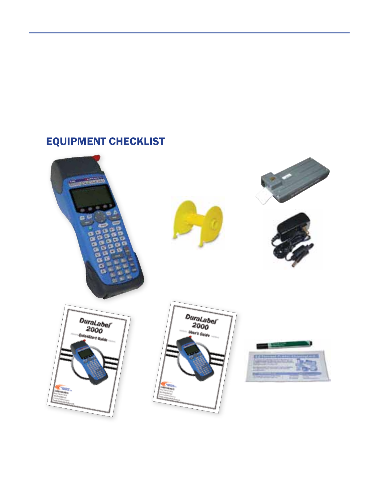
EQUIPMENT CHECKLIST
If any equipment is missing, please contact Graphic Products customer service at
1-800-788-5572.
QuickStart
Guide
User’s
Guide
DuraLabel 2000
Rechargeable Battery
and Battery Charger
Supply Spindle
(shipped inside printer)
Cleaning
Cards (5)
and Pen
-3-
2. GETTING STARTED
Page 7
INSERTING & REMOVING BATTERY
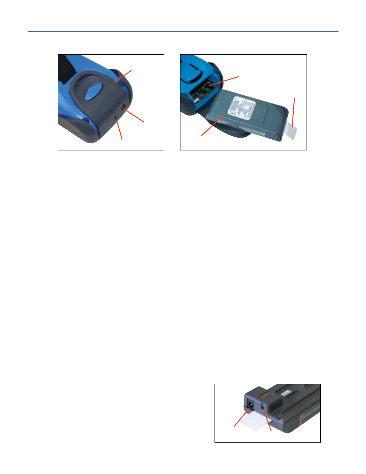
1. Pull up and out on the end of the rubber battery compartment flap on the bottom
of the printer to open the battery compartment.
2. Slide the battery into the printer until it snaps into place.
uNOTE: The printer automatically turns on when the battery is installed.
3. Close the battery compartment flap.
4. To remove the battery, open the battery compartment flap and pull gently on
the pull tab on the end of the battery until it freely slides out.
uNOTE: Do not remove the pull tab.
uCAUTION: Always power down the printer before removing the battery to prevent damage to the LCD.
CHARGING THE BATTERY
The battery is pre-charged. There is no need to charge the battery prior to using
theDuraLabel2000forthersttime.Whenthebattery needs to be recharged,
plug one end of the battery charger into the battery and the other end of the
charger into an electrical outlet. Allow approximately 5 hours to fully charge.
uNOTE: The printer is not designed to operate while the battery is charging.
uWARNING: Always dispose of batteries properly. For more information, visit www.rbrc.org
LED STATUS BATTERY
On ..................................................... Charging
Blinking every 2 seconds ................ Fully Charged
Blinking every 1/2 second ............. Error
Battery
Compartment
Flap
LED Window
Pull Tab
Battery
Compartment
Battery
Power Jack
Window
LED
Power
Jack
3. The BATTERY
Page 8

USING THE BATTERY
The DuraLabel 2000 has an intelligent battery voltage monitor. As the voltage drops,
thermwaredrivesthebatteryhardertodeliverthevoltageneededtomaintainhigh
print quality—even as the battery becomes completely discharged. Printed labels
maintain the same high quality right up until the battery is completely exhausted.
Printing large characters and/or large labels requires more power than small ones
and will drain the battery faster.
Battery usage is monitored by the printer internally to maximize battery life. If the
printer is on and not in use after approximately 15 minutes, the printer saves the cur-
rent label design and powers off to preserve the battery. When the printer is turned
on again, the printer will resume from the same screen as when it powered off.
uWARNING: Riskofreorexplosionifthebattery is replaced by an incorrect type. Use only a Graphic
Products approved battery.
Battery Life Indicator
Full Battery Partial Battery Empty Battery
-5-
3. The BATTERY cont.
Page 9
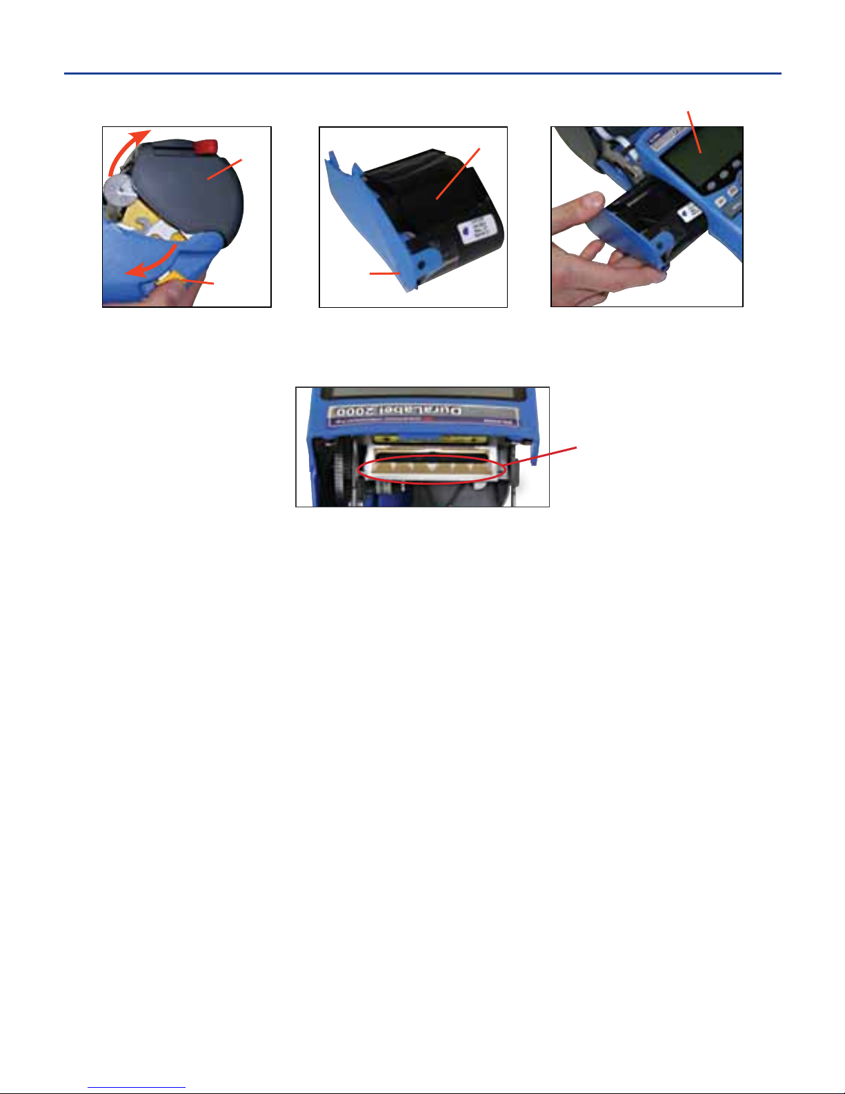
INSTALLING THE RIBBON CARTRIDGE
1. Open the printer cover by pulling the cover release lever.
uNOTE: Do not touch the print head. This could damage the print head and reduce print quality.
2. Orient the ribbon cartridge so that the section of exposed ribbon faces up,
toward the underside of the LCD screen.
3. Gently slide the ribbon cartridge into the side of the printer (avoid snagging
or wrinkling the ribbon) until it snaps tightly and is flush with the side of the
printer. Lock the ribbon cartridge in place by sliding the locking tab.
LCD Screen
Printer
Cover
Cover
Release
Lever
Ribbon
Locking
Tab
Print Head
-6-
4. LOADING PRINTER SUPPLIES
Page 10
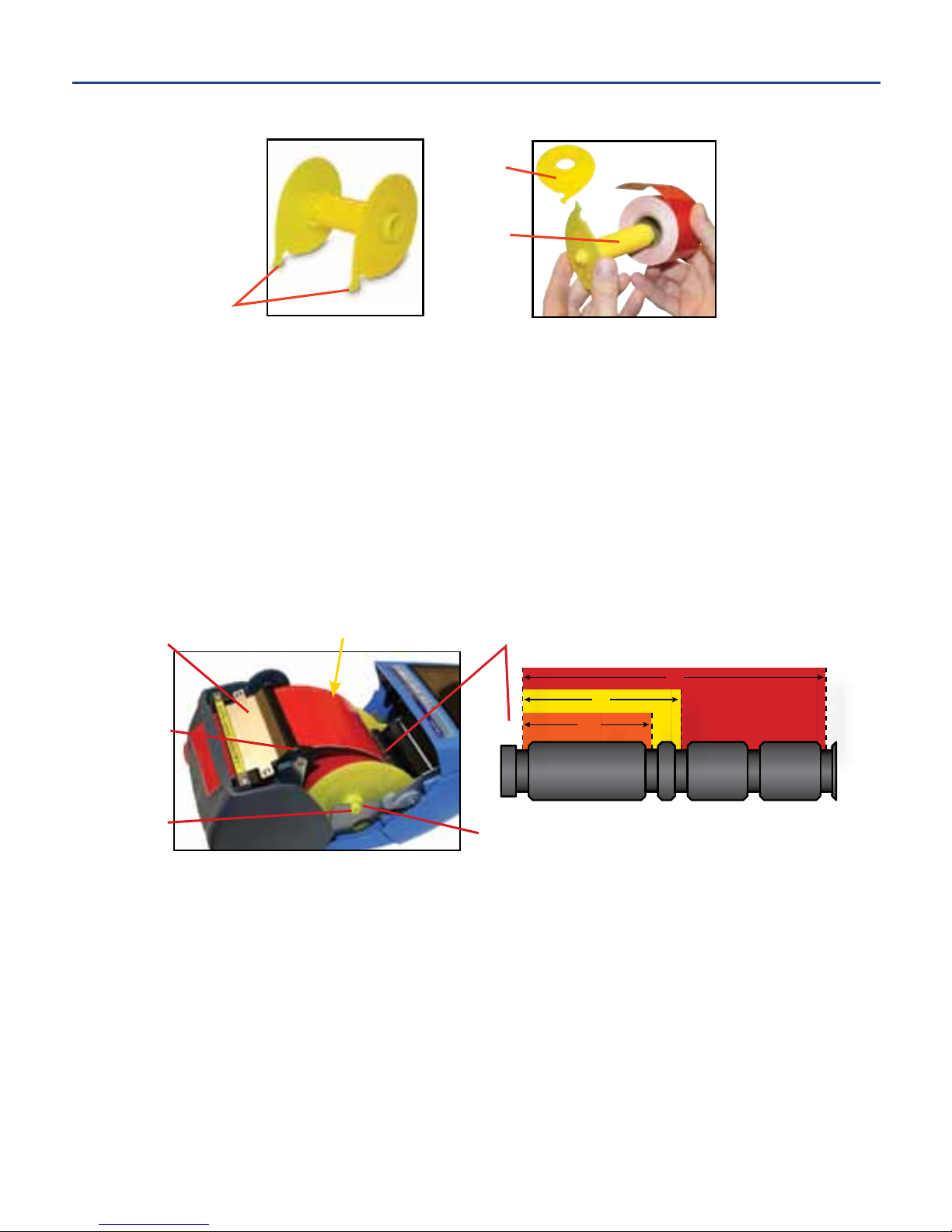
LOADING THE SUPPLY SPINDLE
1. With the printer cover open, remove the supply spindle from the printer.
2. Grasping the two sides of the supply spindle, gently pull it apart.
3. Slide the supply over the spindle shaft making sure it unwinds in the direction
indicated by the arrows on each side of the supply spindle.
4. Replace the spindle cap on the end of the spindle shaft by pressing the ends
together until they touch the supply roll, making sure the spindle hooks are aligned.
INSTALLING THE SUPPLY SPINDLE IN THE PRINTER
1. To secure the supply, place the spindle hooks in the corresponding slots on
the slotted round bar, as seen in the diagram above.
2. Press the spindle shaft ends into the spindle slots.
3. Insert the end of the supply between the platen roller and the black strip of the
guide plate, pushing it through the slot at the top of the printer cover.
4. Carefully close the printer cover without pinching the supply inside, and lock
it in place with the cover release lever.
uNOTE: Once the printer cover is closed, the printer determines the width of supply, and the supply is
aligned for printing labels.
Guide
Plate
Platen
Roller
Slotted Round BarGently push while closing
Spindle
Shaft
End
Spindle
Slot
Supply Spindle
Spindle
Hooks
Spindle
Shaft
Spindle
Cap
4. LOADING PRINTER SUPPLIES cont.
2”
½”
1”
Page 11
To introduce the process of making labels, it is necessary to understand the
different keys found on the printer’s interface and the unique screens with which
the user frequently interacts.
KEYS
The DuraLabel 2000 contains 63 keys used for easy menu navigation, label
design, and printer operation.
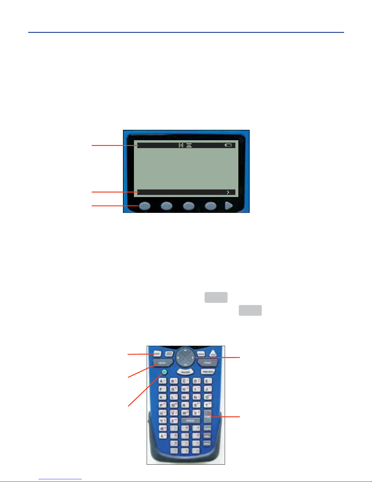
Soft Keys
Five soft keys are located just below the LCD screen. The function for each soft key
appears on the soft key menu bar above each soft key. This allows the user to
navigate between menu options when designing labels or adjusting printer settings.
Keypad
The keypad consists of all keys located below the soft keys. Keys on the keypad
generally serve one basic function, unless the FUNC key is pressed prior to
entering a letter or number on the keypad. Pressing the FUNC key activates the
red key set on the keypad. The arrow on the far left side of the status bar
indicates red key set is active (see page 10).
FILE TEXT IMAGE ALIGN
A 182 AP 1/1
Soft Key Menu
Soft Keys
Status Bar
Power Key
Menu Key
Escape
Direction Pad
Function Key
-8-
5. MAKING LABELS
Page 12
Pressing the power key turns the printer on and off.
The direction pad is used for screen navigation and cursor placement.
Pressing MENU on the key pad will return user to the soft-key main menu from
any screen. The soft-key main menu looks like this:
Pressing ESC on the key pad will return to the previous soft-key menu.
SCREENS
The DuraLabel 2000 has three design screens to aid in designing labels: the
edit screen, the size screen, and the image screen. Two other screens, used
most commonly when a label design is complete, may also be utilized: the pre-
view screen, and the save screen.
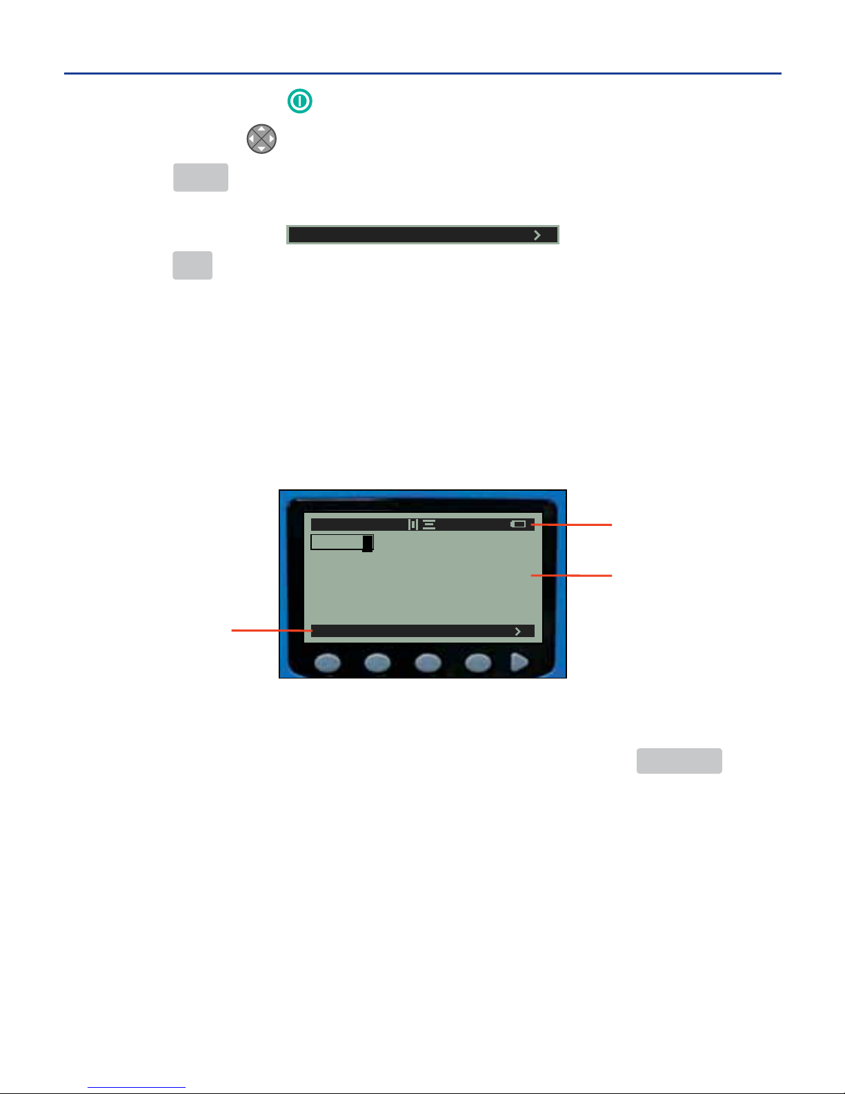
Edit Screen
The edit screen consists of a status bar, a label layout area, and a soft-key menu.
Textandimagesareenteredandmodiedonthisscreen.Theeditscreendis-
plays the layout of the text and images in the label design. Pressing PREVIEW
displays a representation of the label text and images scaled to actual print size.
uNOTE: For further information on what is included on the edit screen, see the Edit Screen Guide on
page 10.
FILE TEXT IMAGE ALIGN
A 182AP 1/1
HALON
Soft Key Menu
Status Bar
Label Layout
Area
FILE TEXT IMAGE ALIGN
-9-
5. MAKING LABELS cont.
Page 13
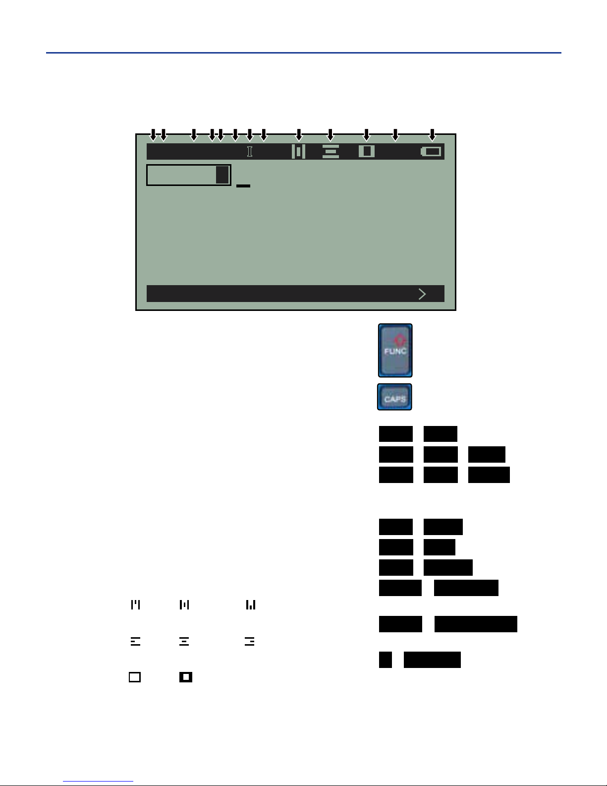
See the explanation of the numbered items below the image.
1.Redkeydenitionsactive ...................................
2. CAPS lock .............................................................
A (on) a (off)
3. Size ....................................................................... TEXT SIZE
4. Auto-size ............................................................... TEXT SIZE AUTO
5. Unit ....................................................................... TEXT SIZE UNITS
P (point size) % (percent of label)
" (height in inches) M (height in millimeters)
6. Bold ...................................................................... TEXT BOLD
7. Italic ...................................................................... TEXT ITAL
8. Underline .............................................................. TEXT UNDER
9. Vertical alignment ............................................... ALIGN VERTICAL
(top) (center) (bottom)
10. Horizontal alignment ........................................ ALIGN HORIZONTAL
(left) (center) (right)
11. Border ................................................................ > BORDER
(thin) (wide)
12. Line number over label line count
13. Battery life remaining
Edit Screen Guide
FILE TEXT IMAGE ALIGN
HALON
A 182 AP B I U 1/1
1 2 3 45 6 7 8 9 10 11 12 13
-10-
5. MAKING LABELS cont.
Page 14
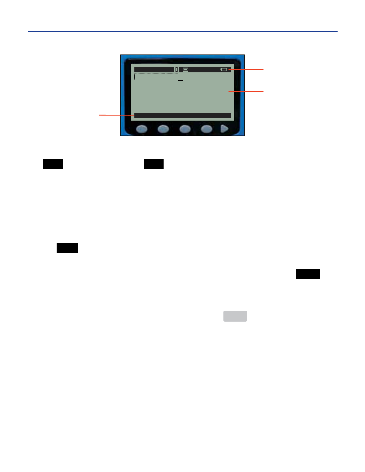
Size Screen
The size screen is accessed through the soft-key main menu by pressing the
TEXT soft key followed by the SIZE soft key. Like the edit screen, the size screen
consists of a status bar, a label layout area, and a soft-key menu.
Intheexampleabove,thesizeis182points,thedefaultfor2"supply.Thelabel
layout area has two sections: one for the text and one for the image.
Whileonthesizescreen,usersmodifythesizeofaspecicstringofcharacters
or images and can adjust the unit of measurement for the label design. Pressing
the AUTO soft key on the soft-key menu allows the user to enable and disable
theauto-sizesettingforaspecicstringofcharactersorimages(tolearnabout
the auto-size feature, see TEXT/IMAGE AUTO-SIZE on page 13). Pressing UNITS
allows the user to change the unit of measurement for the label design to one of the
following: POINT, PERCENT, INCHES, or MM.
To return to the edit screen from the size screen, press MENU.
uNOTE: For information on label design using the size screen, see CELLS on page 14.
AUTO UNITS
182A 182A
A 182A
P
1/1
Soft Key Menu
Status Bar
Label Layout
Area
-11-
5. MAKING LABELS cont.
Page 15
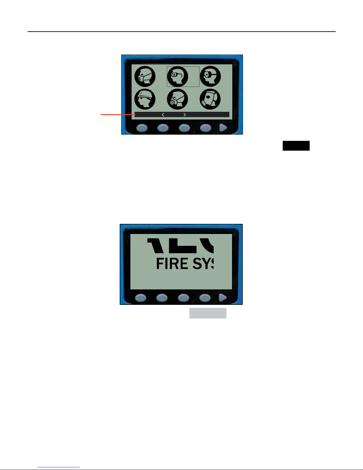
Image Screen
The image screen is accessed through the main menu by pressing the IMAGE
soft key. The image screen displays graphic images found in the DuraLabel 2000
Image Library. Browse the Image Library using the direction pad or by pressing
the options as seen in the soft key menu.
uNOTE: For information on inserting images, see APPLYING GRAPHIC IMAGES TO LABELS onpage18.
Preview Screen
The preview screen is accessed by pressing PREVIEW on the key pad. The
preview screen displays a representation of how a label will appear when printed,
showing text and images scaled to actual size. Scroll through label parts using
the direction pad.
uNOTE: For information on previewing label designs, see PREVIEWING & PRINTING LABELS on page 22.
FIND SELECT
195
198
199 200
196 197
Soft Key Menu
-12-
5. MAKING LABELS cont.
Page 16
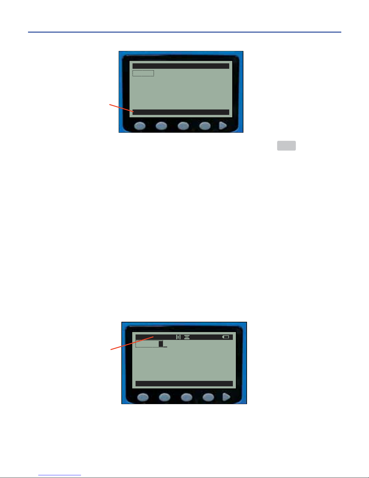
Save Screen
The save screen is accessed through the main menu by pressing the FILE soft key.
The save screen lists the label designs stored on the printer. The soft keys allow
the user to save the current label design, open previously saved label designs, and
delete label designs.
TEXT/IMAGE AUTO-SIZE
Auto-size automatically adjusts the size of the text and images to fill the entire
label area (whether the label consists of one line or many lines). Auto-size
enabled is the printer’s default setting.
Individual text characters, groups of text characters, and images may have auto-
size enabled or disabled, even if they are located within the same line. Auto-size
is denoted by an “A” immediately to the right of the number indicating the current
text or image size in the status bar on the edit screen and the size screen (see
pages 9 and 10).
The “A” also appears on the size screen in the label layout area (see size screen
image on page 10).
uNOTE: Do not get this “A” confused with the “A” that represents CAPS lock on, which is on the far
left side of the status bar.
NEW OPEN DELETE DEL ALL
SAVED LA
BELS
3/40 EDIT
[
NEW
]
HALON
JOHN SMITH
SAFETY GLASSES
Soft Key Menu
DISP PRINT TEST
RESET
HALON
A 182A
P
1/1
Auto-size Enabled
-13-
5. MAKING LABELS cont.
Page 17
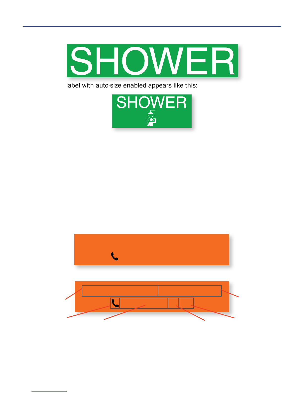
A one line label with auto-size enabled would appear like this:
A two line label with auto-size enabled appears like this:
Auto-size can be disabled by manually changing the size on the size screen.
CELLS
A cell represents text or images that have similar attributes to one another on
the same line. A label design may consist of one or many cells.
New cells are created when text attributes within a line are changed. Each image
is represented by a single cell. Cells are seen on two screens: the edit screen
and the size screen. The following examples illustrate how cells work:
Cells As Seen On the Edit Screen
The first line consists of two cells. The characters of the first cell “JOHN SMITH,”
share the same attributes: bold, and auto-size. The characters of the second cell,
“Receiving Dept.” are italicized and set to size 24 Point.
JOHN SMITH, Receiving Dept.
555-555-5555 ext. 122
JOHN SMITH, Receiving Dept.
555-555-5555 ext. 122
Auto-size
Point
Auto-size
Point
Italics,
Size 24
Point
Size 22
Point
Size 22
Point
Size 15
Point
Finished printed label on 1" supply
Label design showing cells
-14
5. MAKING LABELS cont.
Page 18
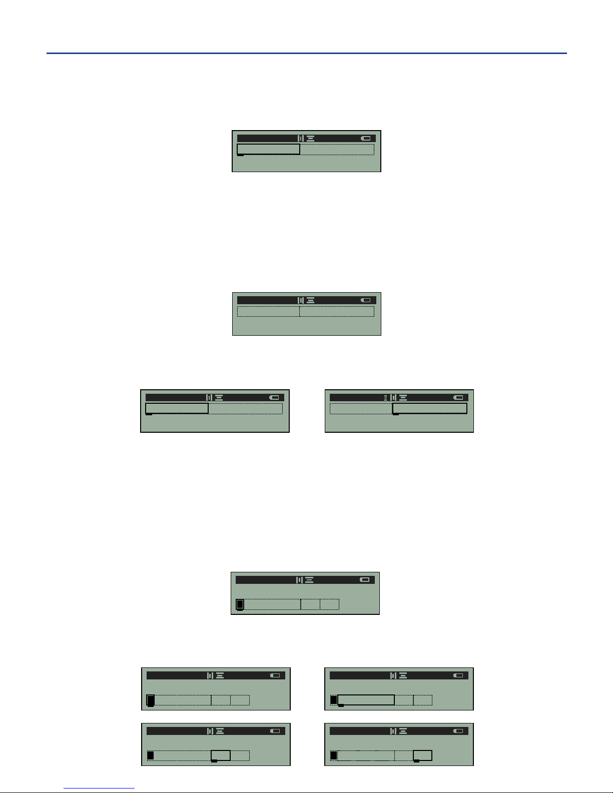
As previously noted, new cells are created when attributes are changed within a
line. As seen in this label example, attributes of the words “JOHN SMITH,” differ
from the attributes of the words “Receiving Dept.”
In the label design process, the italics feature was selected while the cursor lay
under the letter “R” in “Receiving.” This creates a second cell on the first line
beginning with the letter “R.” Italics now applies to all characters after “R” on
the first line until italics is toggled off. In this example, however, no other modifi-
cations are made thereafter, so the first line consists of only two cells.
When the cursor is moved throughout the first line on the label design, the status
bar reflects the current attributes of each unique cell.
The second line consists of four cells on the edit screen. The first cell consists
of the telephone image with auto-size enabled. The second cell begins at the
first “5” in the phone number because auto-size has been disabled and a text
size was manually entered on the size screen. The third cell begins at the “e”
of “ext.” because the text size was reduced, and the fourth cell begins at the
number “1” because the text size of “122” was enlarged again.
When the cursor is moved throughout the second line on the label design, the
status bar reflects the current attributes of each unique cell.
JOHN SMITH, Receiving Dept.
A 31AP 1/1
JOHN SMITH, Receiving Dept. JOHN SMITH, Receiving Dept.
A 31AP 1/1
A 25 P I 1/1
JOHN SMITH, Receiving Dept.
555-555-555 ext. 122
A 31AP 2/2
JOHN SMITH, Receiving Dept.
A 31AP 1/1
JOHN SMITH, Receiving Dept.
555-555-555 ext. 122
A 31AP 2/2
JOHN SMITH, Receiving Dept.
555-555-555 ext. 122
A 22 P 2/2
JOHN SMITH, Receiving Dept.
555-555-555 ext. 122
A 15 P 2/2
JOHN SMITH, Receiving Dept.
555-555-555 ext. 122
A 22 P 2/2
-15-
5. MAKING LABELS cont.
Page 19
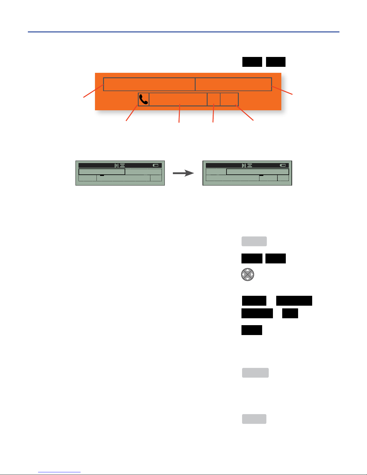
Cells As Seen On the Size Screen
Navigate from the edit screen to the size screen .............. TEXT SIZE
The label design as seen on the size screen appears like this:
When the cursor is moved between cells in a label design, as shown above, the
status bar reflects the attributes of each cell on the line.
CHANGING TEXT/IMAGE SIZE MANUALLY
1. From main menu .............................................................. MENU
2. Change the text/image size manually ............................ TEXT SIZE
3. Move the cursor to the cell where the change is desired .
uNOTE: Changes will also appear on the edit screen.
4. To change unit of measurement ........................................... POINT or PERCENT or
................................................................................................ INCHES or MM
5. Enter the size of the text/image for each cell ................ SIZE 20
uNOTE: Changing the size manually disables auto-size (“A” is removed from status bar).
6a. Apply the text/image size change to the label design and remain on the size
screen .................................................................................... ENTER
or
6b. Apply the text/image size change to the label design and return to the edit
screen .................................................................................... MENU
JOHN SMITH, Receiving Dept.
555-555-5555 ext. 122
Auto-size
(31A)
Auto-size
(31A)
Italics,
Size 24
Point
Size 22
Point
Size 22
Point
Size 15
Point
31A
31A
22 1
31A
A 31AP 1/2
31A
24
15 22
22
A 24 P I 1/2
-16-
5. MAKING LABELS cont.
Page 20
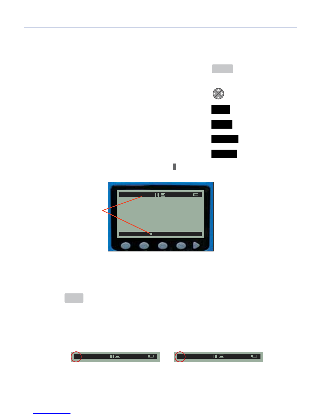
MODIFYING TEXT STYLE ATTRIBUTES
Bold, Italics, and Underline
1. From the main menu ........................................................ MENU
2. Move the cursor underneath the first character to be
modified .................................................................................
3. Modify the text style attributes ........................................ TEXT
4a. Enable or disable the bold style .................................... BOLD
4b. Enable or disable the italics style ................................. ITALICS
4c. Enable or disable the underline style ........................... UNDER
uNOTE: An enabled text style attribute is denoted by a “
” to the style name’s right on the soft key
menu, and depending on the text style (s) enabled, a “B,” “I,” or “U” appears on the status bar.
uNOTE: Once enabled, the text style attribute applies to the modified text character and subsequent
characters until the text style is changed again.
Uppercase and Lowercase
Pressing CAPS toggles text between uppercase and lowercase letters. A capital “A”
appears on the far left side of the status bar, indicating CAPS lock is on, and
characters typed on the keypad appear uppercase. CAPS lock on is the printer
default. A lowercase “a” indicates CAPS lock is off, and characters typed on the
keypad appear lowercase.
a 31AP 2/2
A 31AP 2/2
Status bar showing CAPS lock indicator on left side.
-17-
5. MAKING LABELS cont.
SIZE BOLD ITAL UNDER REV
A 182AP B 1/1
Bold text style
enabled
Page 21
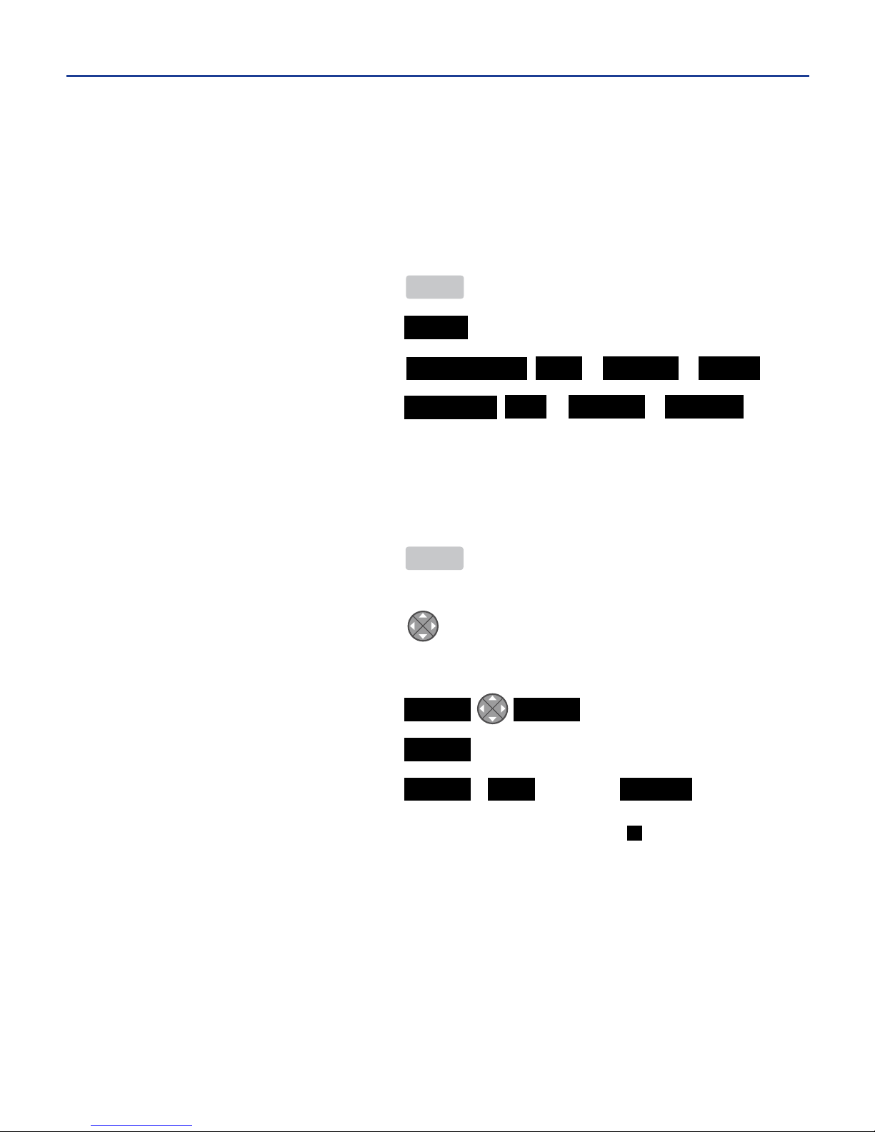
Line Justification
The align feature applies the selected horizontal or vertical alignment to the
label. The default horizontal alignment is center. The default vertical alignment
is center.
Modify the line justification for a label:
1. From the main menu ..................... MENU
2. Select the alignment ..................... ALIGN
3. Modify the horizontal alignment ... HORIZONTAL LEFT or CENTER or RIGHT
4. Select the vertical alignment ........ VERTICAL TOP or CENTER or BOTTOM
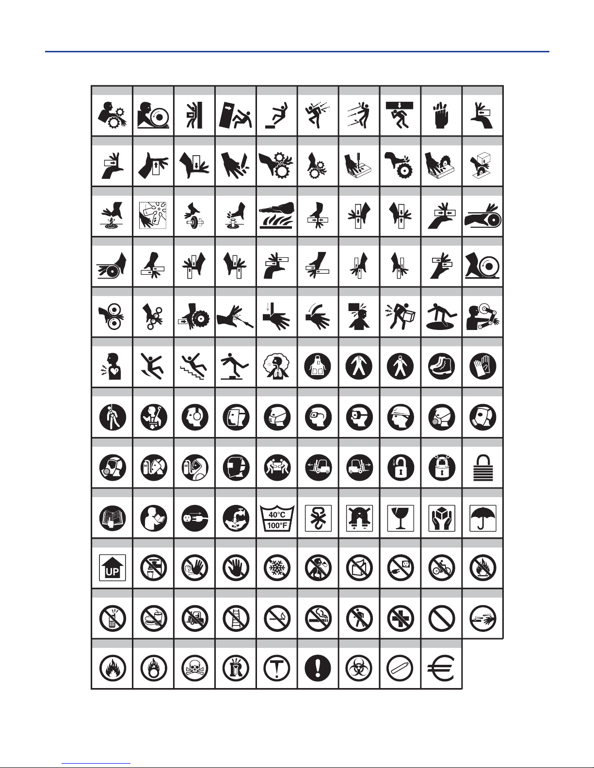
APPLYING GRAPHIC IMAGES TO LABELS
Images found in the Image Library (pgs 19-20) are preinstalled on the DuraLabel
2000.
1. From the main menu ..................... MENU
2. On the edit screen, place the cursor in the desired location in the label
layout area ........................................
3. Do one of the following:
a) Insert an image ......................... IMAGE ENTER
b) Insert an image ......................... IMAGE < > SELECT
c) Insert an image ......................... IMAGE FIND 001-249 SELECT
uNOTE: On the edit screen, a graphic image will appear as a black place holder ( ).
-18-
5. MAKING LABELS cont.
Page 22
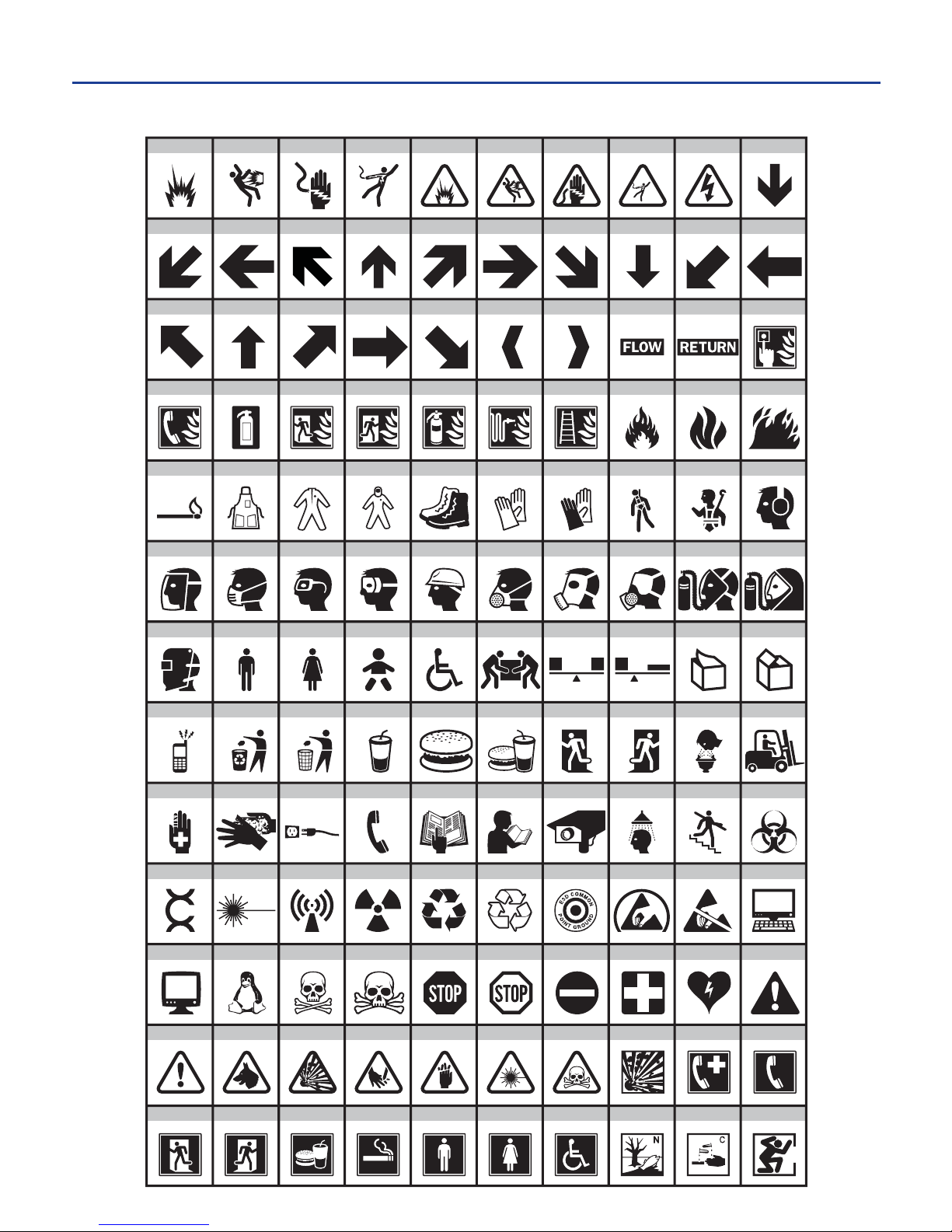
THE IMAGE LIBRARY
-19-
5. MAKING LABELS cont.
4
14
24
34
44
54
64
74
84
94
104
10
20
30
40
50
60
70
80
90
100
110
120
1
11
21
31
41
51
61
71
81
91
101
111
2
12
22
32
42
52
62
72
82
92
102
112
3
13
23
33
43
53
63
73
83
93
103
113 114
5
15
25
35
45
55
65
75
85
95
105
115
6
16
26
36
46
56
66
76
86
96
106
116
7
17
27
37
47
57
67
77
87
97
107
117
8
18
28
38
48
58
68
78
88
98
108
118
9
19
29
39
49
59
69
79
89
99
109
119
130
121 122 123 124 125
126
127 128 129
Page 23
-20-
5. MAKING LABELS cont.
140
150
160
170
180
190
200
210
220
230
240
131
141
151
161
171
181
191
201
211
221
231
241
132
142
152
162
172
182
192
202
212
222
232
242
133
143
153
163
173
183
193
203
213
223
233
243
134
144
154
164
174
184
194
204
214
224
234
244
135
145
155
165
175
185
195
205
215
225
235
245
136
146
156
166
176
186
196
206
216
226
236
246
137
147
157
167
177
187
197
207
217
227
237
247
138
148
158
168
178
188
198
208
218
228
238
248
139
149
159
169
179
189
199
209
219
229
239
249
Page 24
FILE TEXT IMAGE
ALIGN >
A 37 AP 1/1
SRE091753
WATCH YOUR STEP
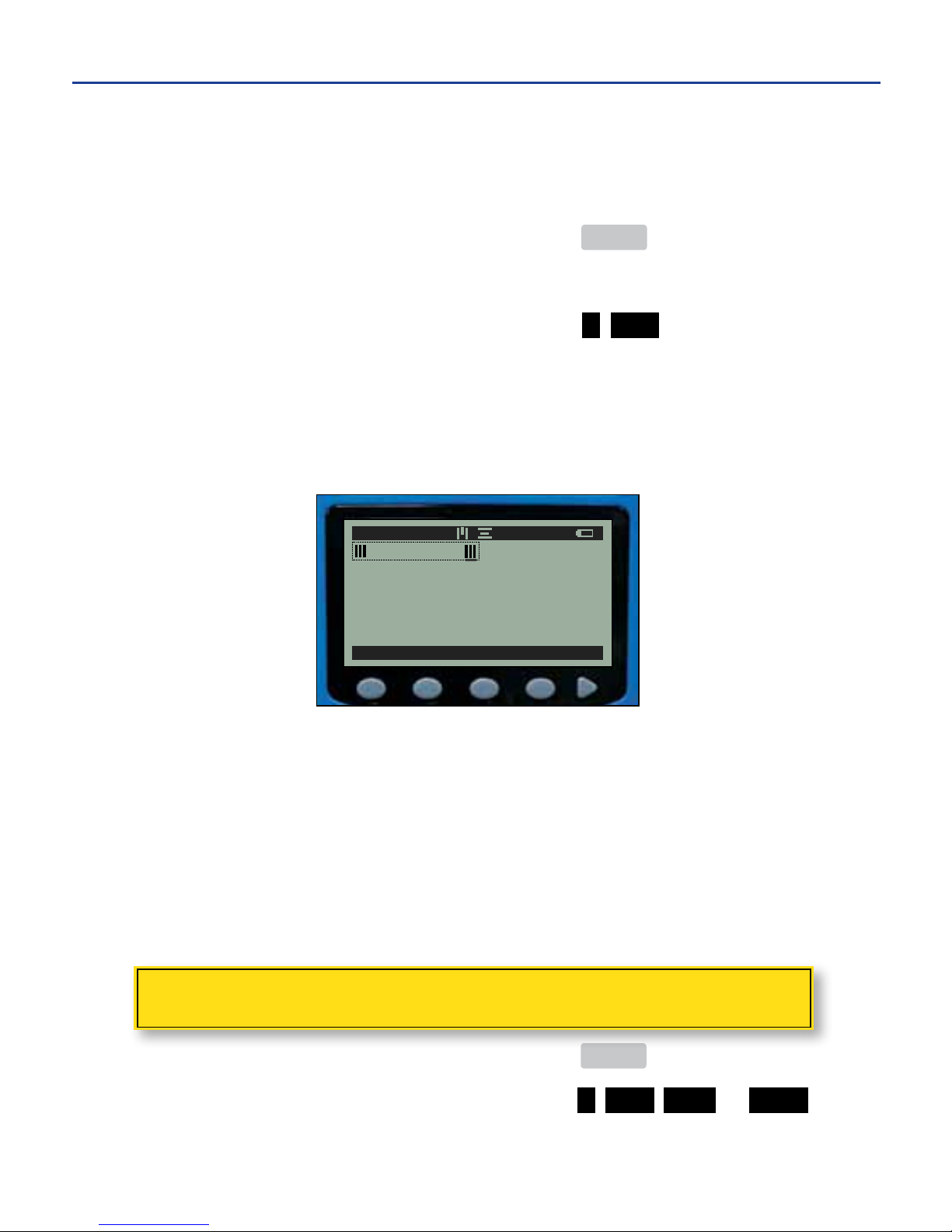
CREATING BAR CODES
Bar codes may be printed on labels using Code 39 symbology. Bar codes can be
created above, below, or on either side of text during the label design process.
1. From the main menu ................................................... MENU
2. On the edit screen, position the cursor where you want the bar code to appear.
3. Create bar code cell ..................................................... > BAR
4. With the cursor positioned within the bar code cell on the right side, type the
desired bar code characters.
uNOTE: Moving the cursor to the left side within the bar code cell and typing with the keypad
positions characters outside of the bar code (i.e., characters appear separate from and to the left
of the bar code). Text entered from this position does not translate into printed bar code characters.
The following character sets are allowable in Code 39 symbology:
Numerals (0-9) Uppercase letters (A-Z)
Special characters (. / + - $) Blank spaces
uNOTE: Entering characters other than those in the allowable character sets will print but will not be
read by a bar code scanner.
ADDING A BORDER
Place a border around the entire contents of a label.
1. From the main menu ................................................... MENU
2. Add a border ............................................................. > BAR THIN or WIDE
uNOTE: A thin border is approximately .5 mm wide. A wide border is approximately 1 mm wide.
5. MAKING LABELS cont.
-21-
Page 25
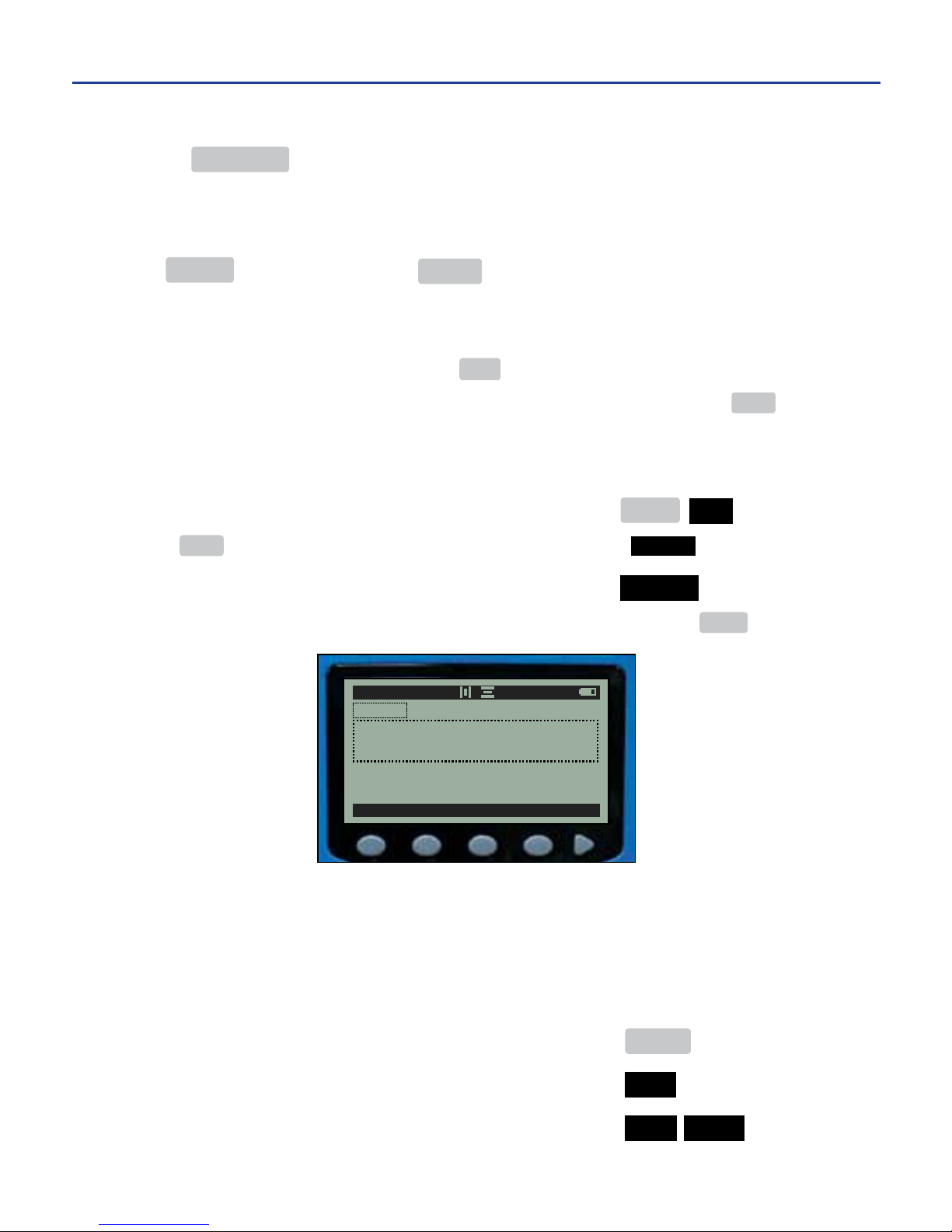
PREVIEWING & PRINTING LABELS
Pressing PREVIEW from any screen displays a representation of the label design
as it appears when printed. The preview screen shows text and images to actual
size. Use the arrows on the direction pad to view other parts of the label design.
Press PRINT to print your label or MENU to go back and edit your label design.
When the label is finished printing, pull down on the red cutter lever to cut the
label. The label roll is set, and the printer is ready to print the next label. To
cancel the print job at any time, press ESC.
uNOTE: If the printer’s auto-feed setting is off (see page 27), it is necessary to first press FEED to feed
the remaining printed portion of the label from the printer prior to cutting the label.
DELETING CURRENT LABELS
1. Delete a current label and clear the edit screen .......... FUNC DEL
uNOTE: FUNC activatestheredkeydefinitions(seepage8),inthiscaseDEL ALL.
2. When the message “Delete label?” appears ................ DELETE
uNOTE: To leave the currrent screen without deleting the current label design, press MENU.
SAVING LABELS
A label design remains on the edit screen until it is saved or deleted, even if
the printer is turned off and back on. When replacing a label design with a new
design, the printer prompts the user to name the label design to be saved.
1. Return to the main menu ................................................ MENU
2. Go to the save screen ...................................................... FILE
3. Save the label .................................................................. NEW SAVE
4. Type the label name ........................................................ HALON
DELETE
HALON
Delete label?
A 182A
P B
1/1
-22-
5. MAKING LABELS cont.
Page 26
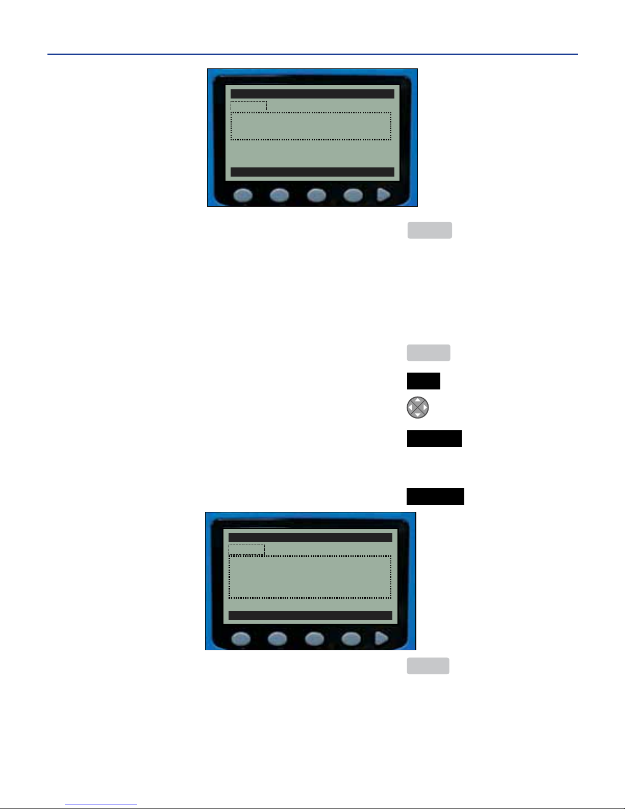
5. Acceptthelename ........................................................ ENTER
The label is now saved, and the user is returned to the default edit screen to
begin a new label.
uNOTE: Up to 32 labels can be stored in the printer at one time.
DELETING SAVED LABELS
1. From the main menu ....................................................... MENU
2. Go to save screen ............................................................ FILE
3. Select the label to be deleted ........................................
4a. Delete the label ............................................................. DELETE
or
4b. Delete all saved labels .................................................. DEL ALL
5. Return to the main menu ............................................... MENU
DELETE
SAVED LA
BELS
1/32 EDIT
[
NEW
]
HALON
Delete label?
HALON
SAVE DELETE
SAVED LA
BELS
1/32 EDIT
[
NEW
]
HALON
Save current file?
-23-
5. MAKING LABELS cont.
Page 27
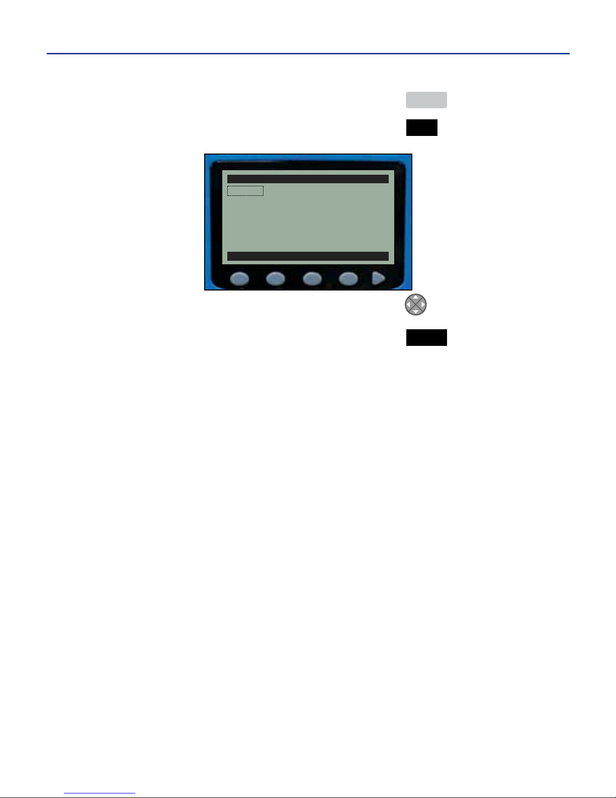
OPENING SAVED LABELS
1. From the main menu ............................................................ MENU
2. Go to the save screen ...................................................... FILE
3. Select the label to open ...................................................
4. Open the label .................................................................. OPEN
NEW OPEN DELETE DEL ALL
SAVED LA
BELS
3/32 EDIT
[
NEW
]
HALON
JOHN SMITH
SAFETY GLASSES
-24-
5. MAKING LABELS cont.
Page 28
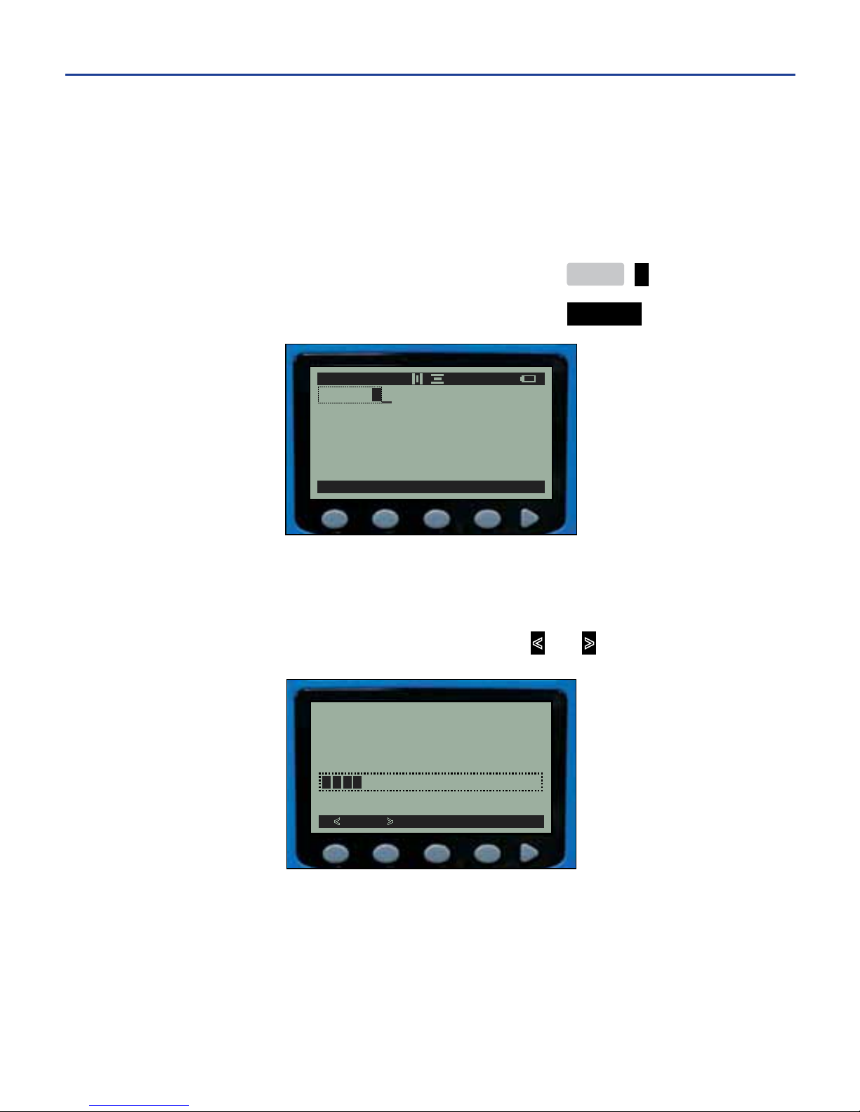
OPTIMIZING PERFORMANCE & QUALITY
The DuraLabel 2000 allows users to adjust system settings for optimal printer
performance and print quality. System settings including display screen contrast,
print head temperature, motor speed, auto-feed, test printing and system reset
are accessed from the soft key main menu:
1. From the main menu ........................................................ MENU >
2. Go to the system settings ................................................. SYSTEM
DISP (Display)
On this screen, the user may decrease or increase the contrast level of the LCD
screen—making it brighter or darker—by pressing the
< and > soft keys.
Contrast Adjustment
< >
DISP PRINT TEST
RESET
A 182 AP
HALON
-25-
6. PRINTER SYSTEM SETTINGS
Page 29
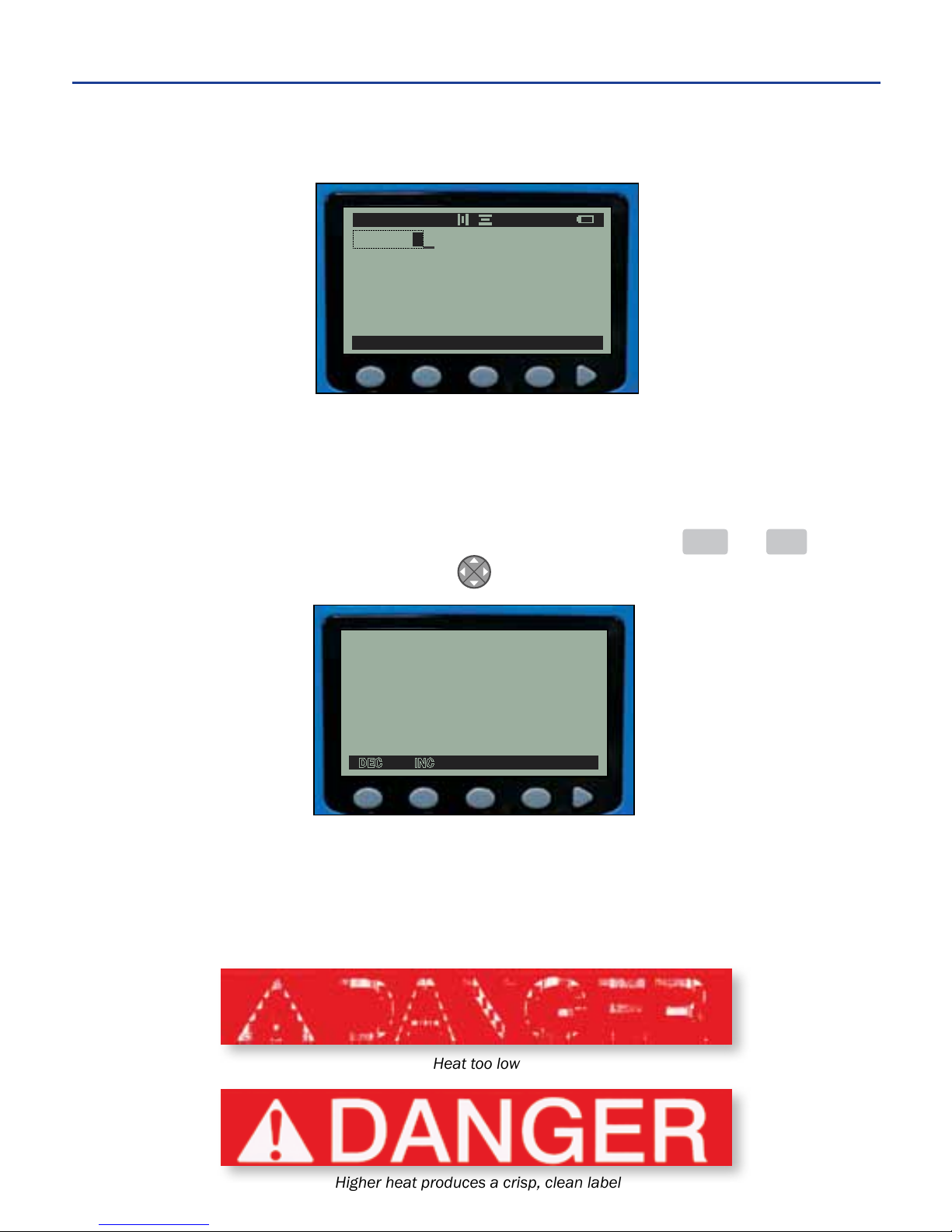
PRINT
This soft key directs users to another series of soft key options related to printing:
Print head heat settings, motor speed settings, and auto-feed settings are
adjusted here.
Heat
Print head heat may be decreased or increased by pressing the DEC and INC
soft keys or by using the direction pad .
This setting is useful when printed characters appear spotty, blurred, uneven, too
dense or faint. Increasing heat causes printed characters to appear darker and
denser; however, too much heat can cause an undesireable pattern to appear.
Adjust the temperature to achieve optimal print quality.
Heat Adjustment =
+1
DEC INC
Heat too low
Higher heat produces a crisp, clean label
A 182 AP
HALON
HEAT MOTOR FEED
-26-
6. PRINTER SYSTEM SETTINGS
Page 30

uNOTE: See Testonpage28.
Printing on a lower heat setting uses less battery power and allows the printer to
print labels at a faster rate.
Motor
Motor speed (how fast or slowly the motor feeds the label past the print head)
may be decreased or increased by pressing the DEC and INC soft keys or by
using the direction pad.
Feed
When auto-feed is on, the label is automatically advanced past the cutter position
after printing is completed. When auto-feed is off, the user must press FEED to
advance the label after printing is completed.
Disabling auto-feed is useful when designing labels that merge or split lines (see
label example on page 32).
The auto-feed setting may be enabled or disabled with the ON and OFF soft keys.
Motor Adjustment =
-2
DEC INC
A 182 AP
HALON
HEAT MOTOR FEED
-27-
6. PRINTER SYSTEM SETTINGS
Page 31
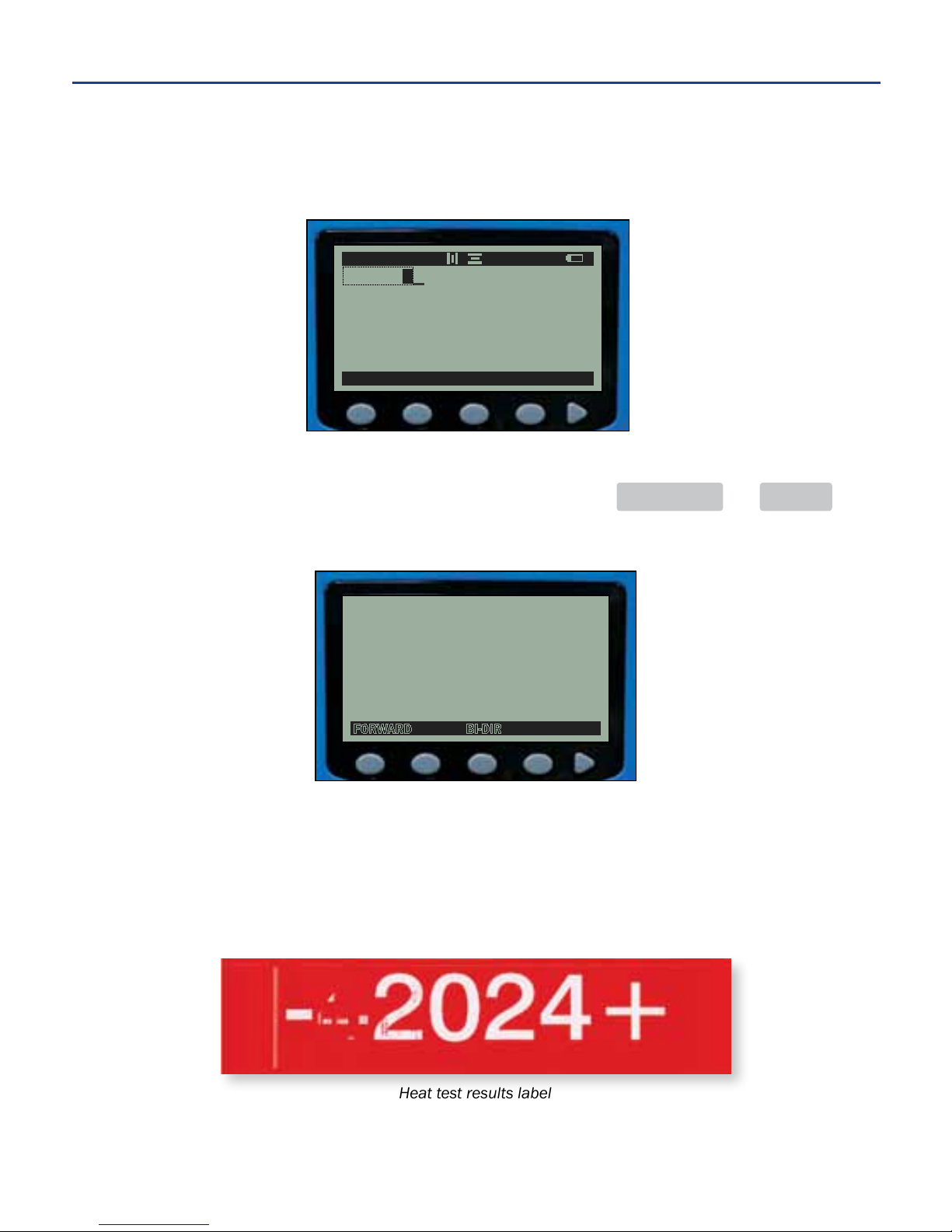
TEST
This soft key directs users to another series of soft key options related to testing
printer performance.
Feed
The printer’s feed feature may be tested by pressing the FORWARD and BI-DIR
(bi-directional) soft keys. Loaded supply feeds from the printer.
Test
This soft key tests print head heat settings by printing heat test results onto the
supply. The user may verify which setting yields the best print results and apply
that heat setting to a label print job. See Heat on page 26.
Select Feed Test
FORWARD BI-DIR
FEED TEST PRINT VER
A 182 AP
HALON
Heat test results label
-28-
6. PRINTER SYSTEM SETTINGS
Page 32
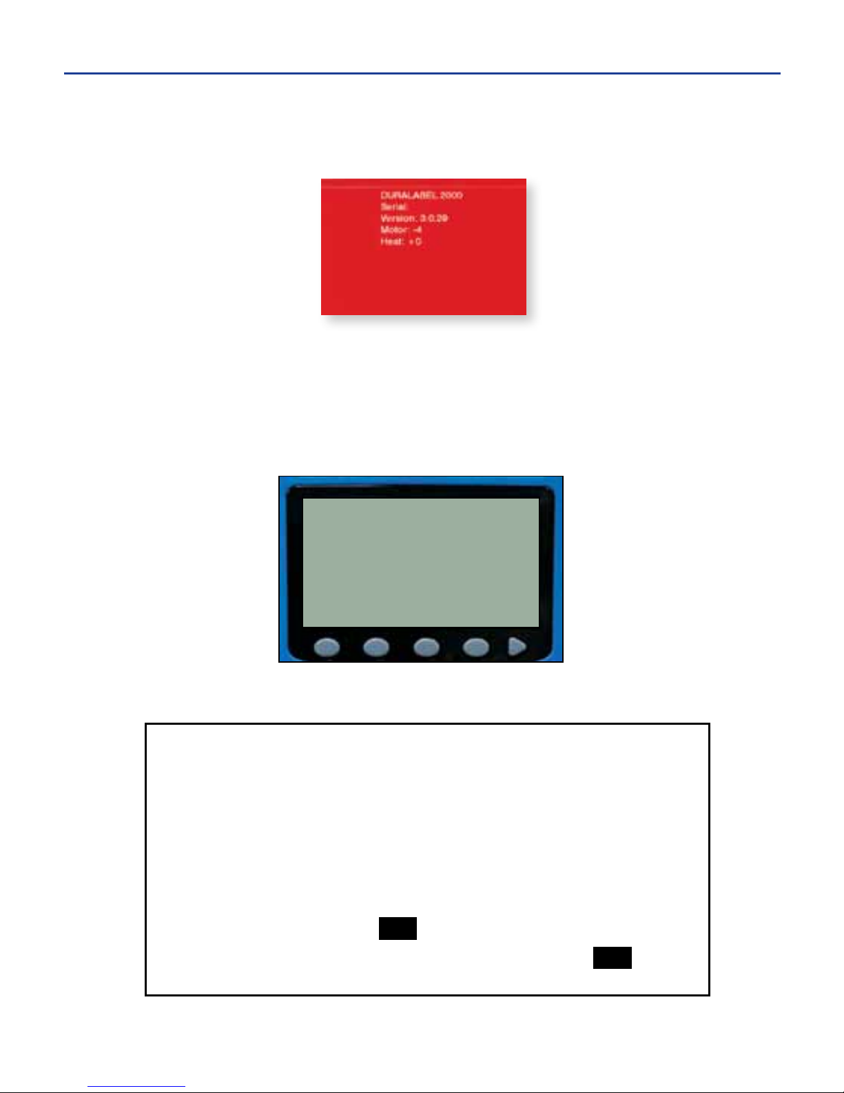
Print Ver
This soft key prints printer version information and current motor and heat settings
onto supply.
RESET
This soft key “reboots” the printer and restores the printer’s default settings. This
option is particularly useful if the printer begins functioning out-of-character and
the printer needs to be restored to its original settings. This screen appears
during the system reset process:
uNOTE: Saved labels are not erased during reset.
HARD RESET
A hard reset may also be performed to return the printer to a
known state if it is functioning “out of character.” To perform a
hard reset,
1. Remove the battery.
2. While holding down the ESC key, reinsert the battery. Once the
batteryisinsertedand"snaps"intoplace,releasetheESC key.
Printer Version
Software Version:
3.1.06
-29-
-28-
6. PRINTER SYSTEM SETTINGS
Page 33
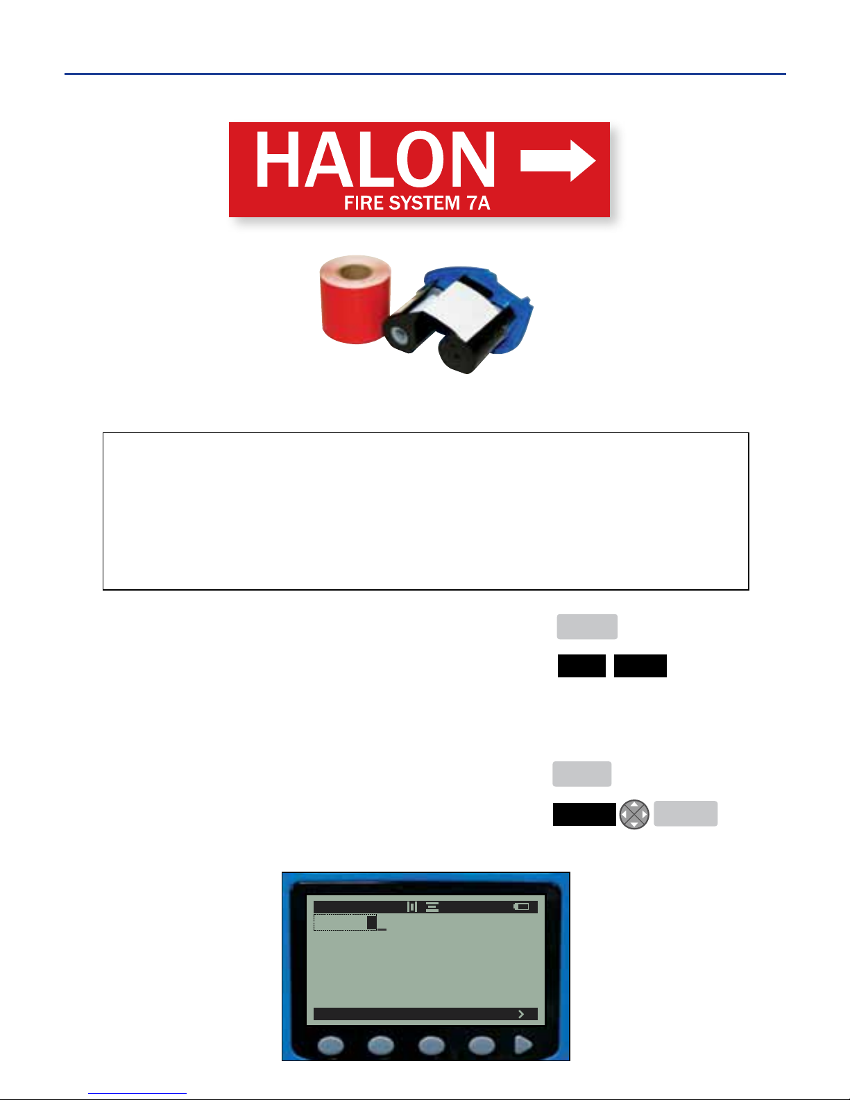
1. From the main menu ....................................................... MENU
2. Enable bold setting.......................................................... TEXT BOLD
uNOTE: When enabled, a small box appears to the right of the menu option.
3. Type the label text ...........................................................HALON
4. Return to the main menu ............................................... MENU
5. Insert an image ...............................................................IMAGE ENTER
uNOTE: The image appears on the edit screen as a black place-holder.
FILE TEXT IM
AGE ALIGN
A 182 AP
HALON
This label’s features and settings:
Two lines of text, one image Auto-feed: enabled
Unit of measurement: POINT CAPS Lock: ON
Auto-size: enabled (1st line)
Label text style: BOLD (1st line)
Example Label Directions #1: PIPE MARKING LABEL
-30-
Finished Label
Red 2" Standard Supply and White Ribbon Cartridge
7. EXAMPLE LABELS
Page 34
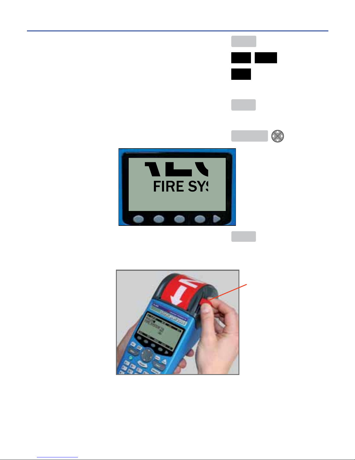
6. Advance to the next line.................................................. ENTER
7. Disable the bold setting .................................................. TEXT BOLD
8. Change the text size to 30 pt ......................................... SIZE 30
uNOTE: The auto-size indicator “A” disappears when the size is manually entered.
9. Return to the edit screen ................................................ MENU
10. Type the label text ......................................................... FIRE SYSTEM 7A
11. Preview the label ........................................................... PREVIEW
12. Print the label ...................................................................PRINT
uNOTE: After printing, cut the label by pulling the red cutter lever down.
-31-
7. EXAMPLE LABELS cont.
Cutter Lever
Page 35
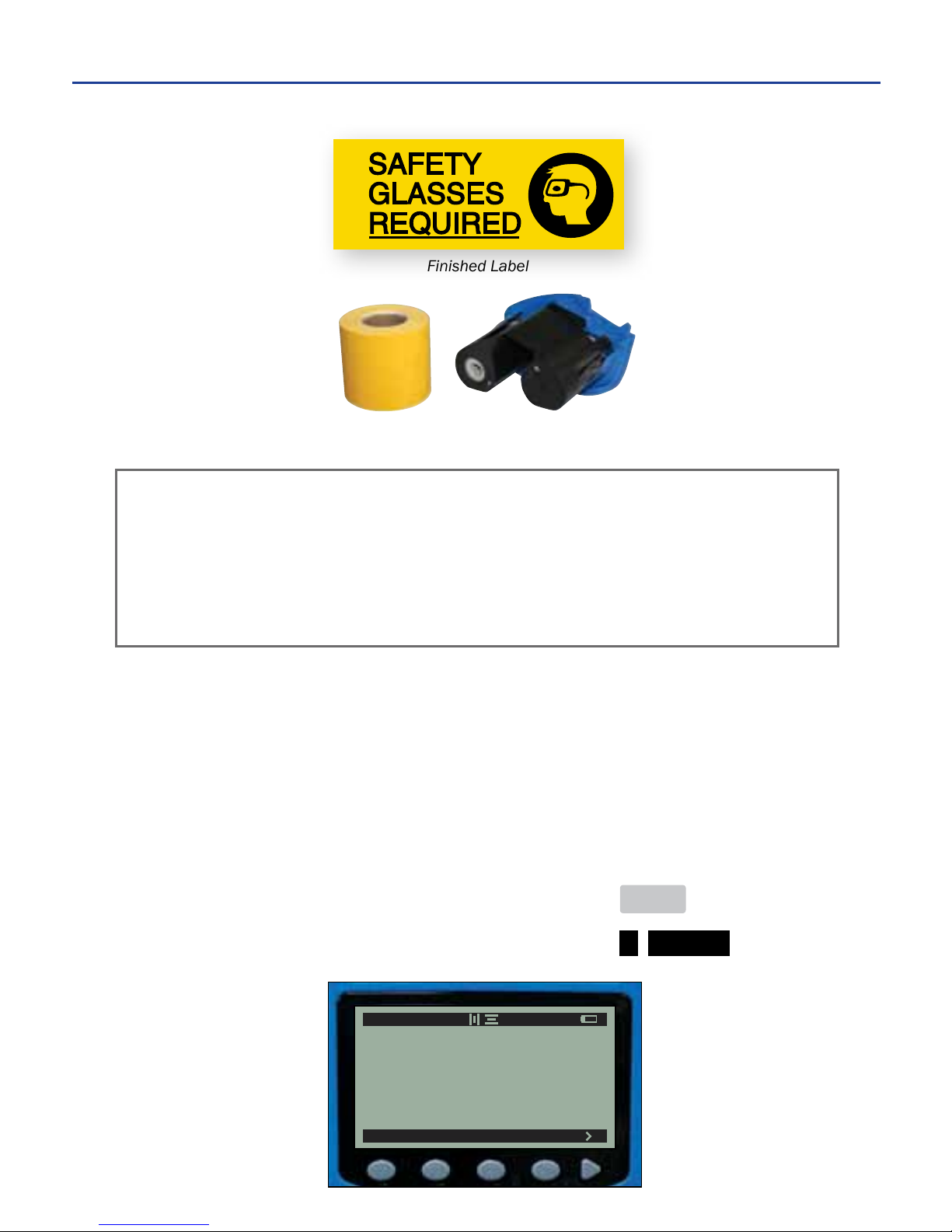
Example Label Directions #2: OSHA SAFETY LABEL
FIRST LABEL DESIGN
Disable Auto-Feed
1. From the main menu ....................................................... MENU
2. Go to the system settings ................................................ > SYSTEM
Yellow 2" Standard Supply
and Black Ribbon Cartridge
Finished Label
This label is created using two separate label designs. Creating the label with
two designs allows the user to merge or split lines. In this example, three lines of
text are merged into one line containing an image. The auto-feed setting must be
disabled for the image to print directly next to the text portion of the label.
This label’s features and settings:
Three lines of text, one image Auto-feed: disabled
Unit of measurement: POINT CAPS Lock: ON
Auto-size: disabled (rst label design)
Label alignment: HORIZONTAL - LEFT and VERTICAL - CENTER.
SYSTEM
A 182AP B 1/1
-32-
7. EXAMPLE LABELS cont.
Page 36
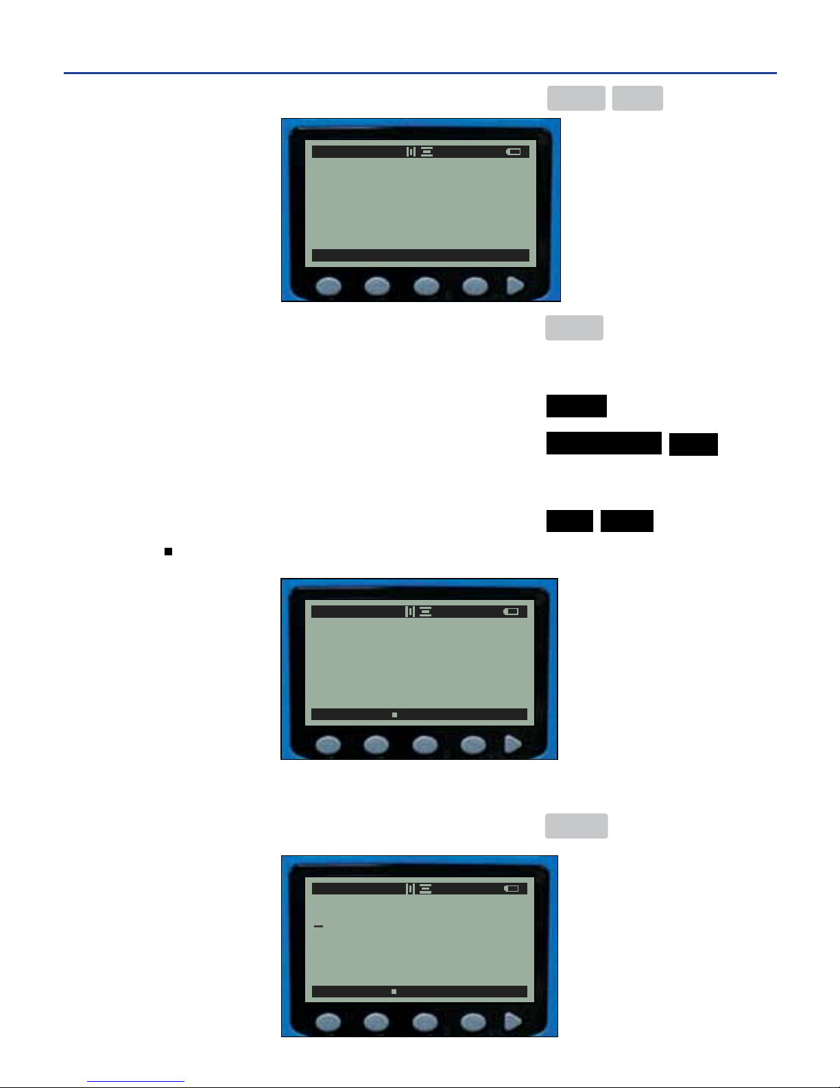
3. Disable auto-feed ............................................................. PRINT FEED
4. Return to the main menu ................................................ MENU
Left Justify Text
5. Select the alignment .......................................................ALIGN
6. Modify horizontal alignment ...........................................HORIZONTAL LEFT
Enable Bold Style
7. Enable the bold style ....................................................... TEXT BOLD
uNOTE: “ ” denotes the text style is enabled
8. Type the label text ............................................................ SAFETY
9. Advance to the next line .................................................. ENTER
HEAT MOTOR FEED
A 1.67A" 1/1
-33-
7. EXAMPLE LABELS cont.
SIZE BOLD ITAL UNDER REV
A 90AP B 2/2
SAFETY
SIZE BOLD ITAL UNDER REV
A 182AP B 1/1
Page 37
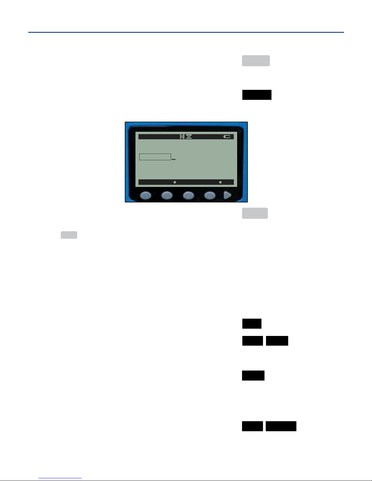
10. Type the label text..........................................................GLASSES
11. Advance to the next line ...............................................ENTER
Enable Bold Style
12. Enable the underline style ............................................ UNDER
13. Type the label text .........................................................REQUIRED
14. Print the label ................................................................ PRINT
uNOTE:Theprinterwillprinttheentire"SAFETYGLASSESREQUIRED"portionofthelabel.DoNOT
press FEED. The supply is now in position to print the second label design (safety glasses image) right
nexttothe"SAFETYGLASSESREQUIRED"portionofthelabel.
SECOND LABEL DESIGN
To create the second label design, begin by saving or deleting the current
“SAFETY GLASSES REQUIRED” label design.
Save or Delete Current Label
1. Go to the save screen ...................................................... FILE
2a. Save the current label ................................................... NEW SAVE
Type the desired label name ........................................ SAFETY GLASSES
Save the current label ................................................... SAVE
A new edit screen appears.
or
2b. Delete the current label ................................................ NEW DELETE
A new edit screen appears.
-34-
7. EXAMPLE LABELS cont.
SIZE BOLD ITAL UNDER REV
A 43AP B 3/3
SAFETY
GLASSES
REQUIRED
Page 38
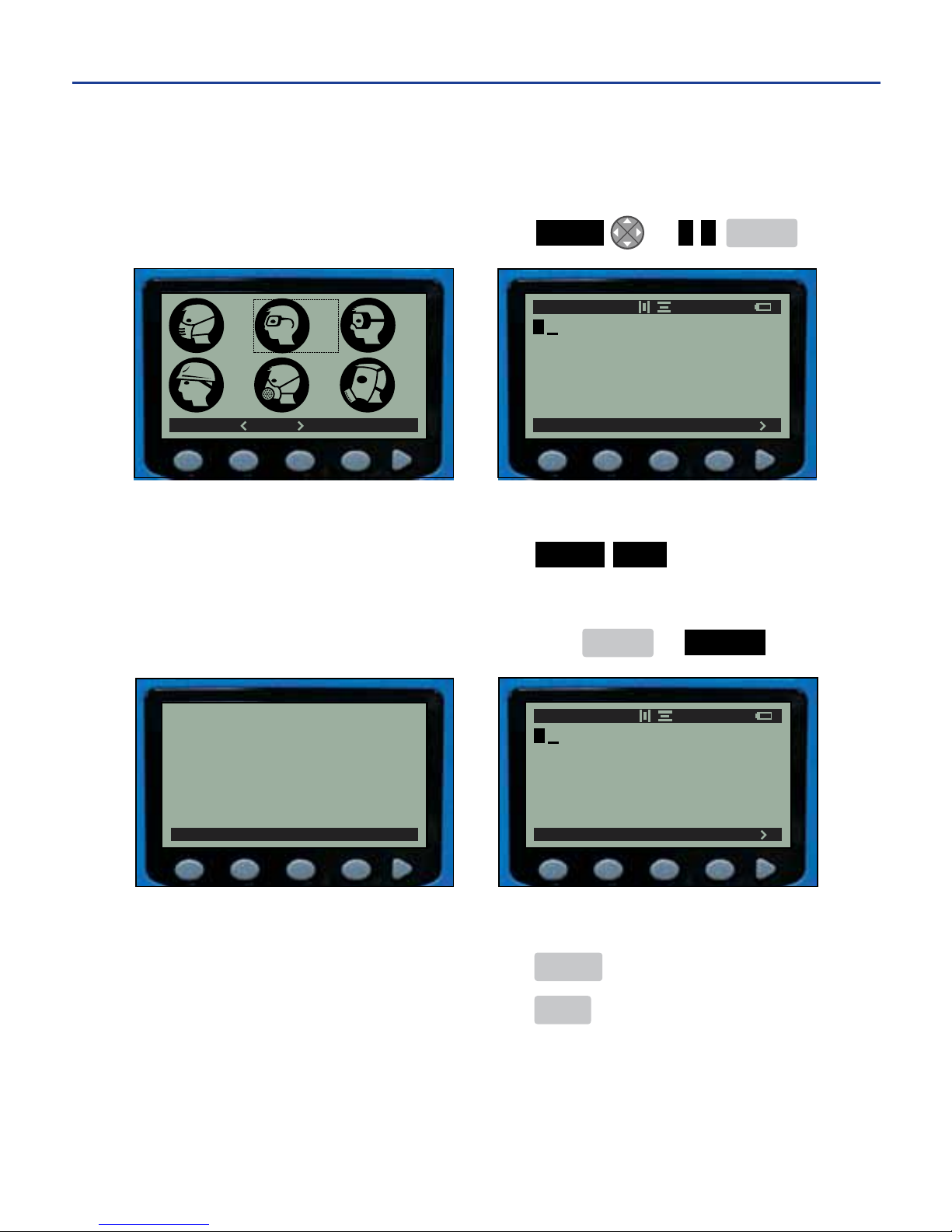
With a new edit screen, the second label design —consisting of the safety glasses
image—can now be created.
Insert Image
3a. Insert the image ............................................ IMAGE or < > ENTER
or
3b. Insert the image ............................................ IMAGE FIND
Refer to the Image Library (pages 19 & 20).
Select the image number .............................196 ENTER or SELECT
uNOTE: The image appears on the edit screen as a black placeholder box.
4. Print the label ................................................... PRINT
5. Feed the label .................................................. FEED
FILE TEXT IMAGE ALIGN
A 182AP 1/1
SELECT
Select Image
196
FILE TEXT IMAGE ALIGN
A 182AP 1/1
FIND SELECT
195
198
199 200
196 197
-35-
7. EXAMPLE LABELS cont.
Page 39
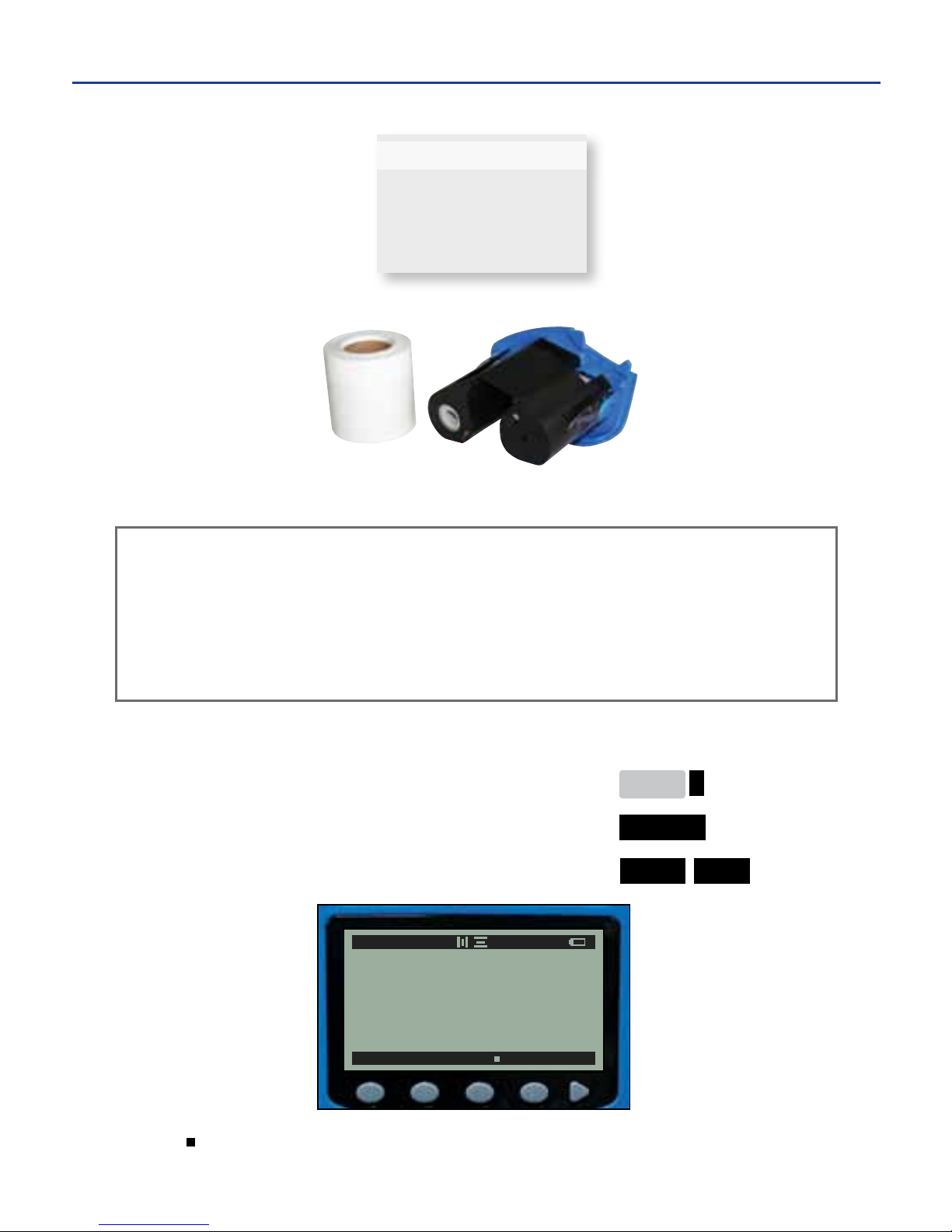
Example Label Directions #3: WIRE WRAP
Enable Auto-Feed
1. From the main menu ....................................................... MENU >
2. Go to the system settings ................................................ SYSTEM
3. Enable auto-feed .............................................................. PRINT FEED
uNOTE: “ ” denotes the text style is enabled
E-11845
This label’s features and settings:
One line of text Auto-feed: enabled
Unit of measurement: INCHES CAPS Lock: ON
Auto-size: disabled
Label alignment: HORIZONTAL - CENTER, VERTICAL - TOP.
White 2" Self-Laminating Wire Wrap with ½" Printable Area
and Black Ribbon Cartridge
Finished Label
-36-
7. EXAMPLE LABELS cont.
HEAT MOTOR FEED
A
1.70A"
1/1
Page 40
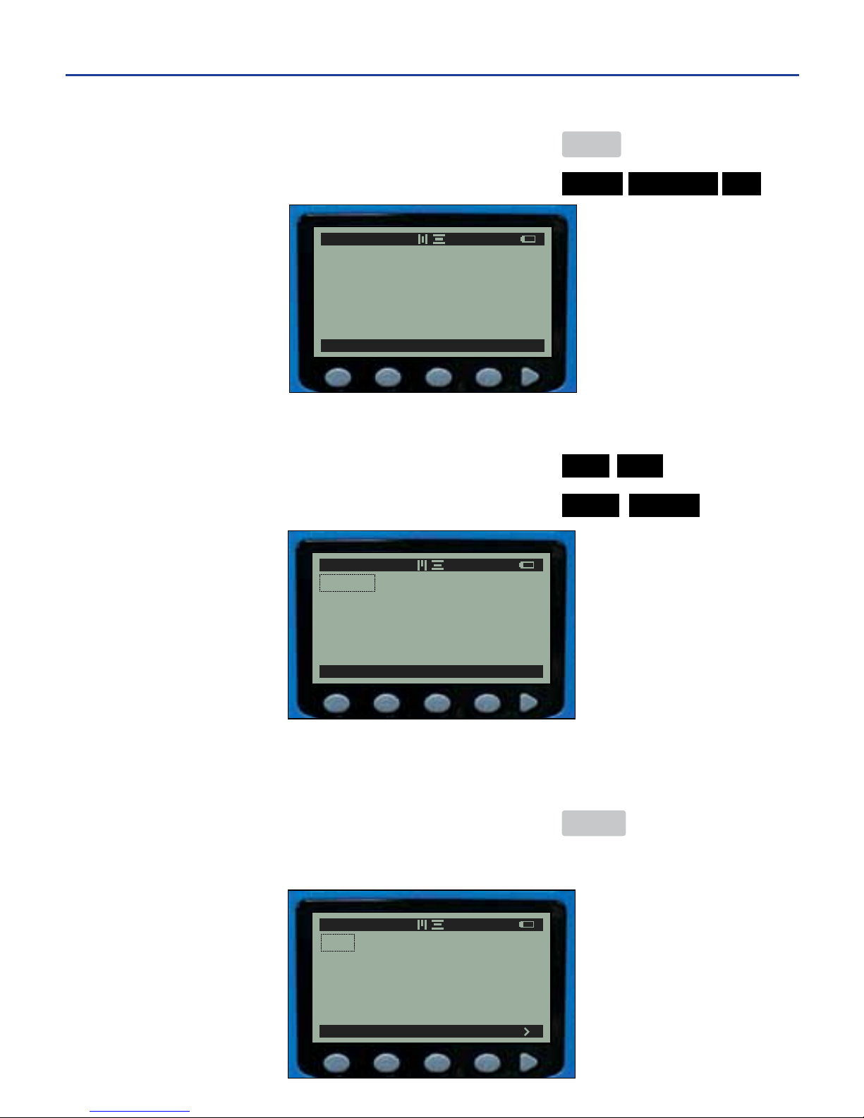
Set Vertical Alignment
4. From the main menu ....................................................... MENU
5. Align the label vertically at the top ................................. ALIGN VERTICAL TOP
Change Unit of Measurement to Inches
6. Go to the size screen ....................................................... TEXT SIZE
7. Change the unit of measurement to inches...................UNITS INCHES
Modify Text Size
8. Type the text size into the cell .........................................50
9.Registerthetextsizemodication .................................. ENTER
uNOTE:Thetextsizenowtstheprintableareaoftheself-laminatingwirewrapsupplyandautomatically
removes the auto-size setting for this line.
TOP CENTER BOTTOM
A 1.70A" 1/1
POINT PERCENT INCHES MM
1.70A
A 1.70A" 1/1
AUTO UNITS
.50
A .50 " 1/1
-37-
7. EXAMPLE LABELS cont.
Page 41
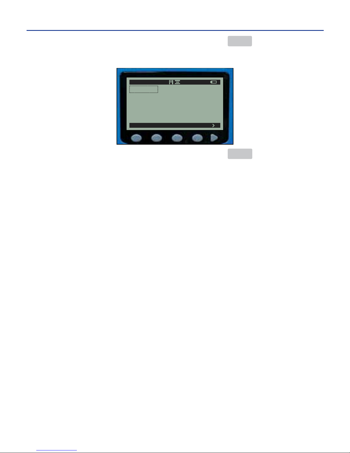
10. From the main menu ..................................................... MENU
11. Type the label text .........................................................E-11845
12. Print the wire wrap ........................................................ PRINT
POINT PERCENT INCHES MM
E-11845
A .50 " 1/1
-38-
7. EXAMPLE LABELS cont.
Page 42
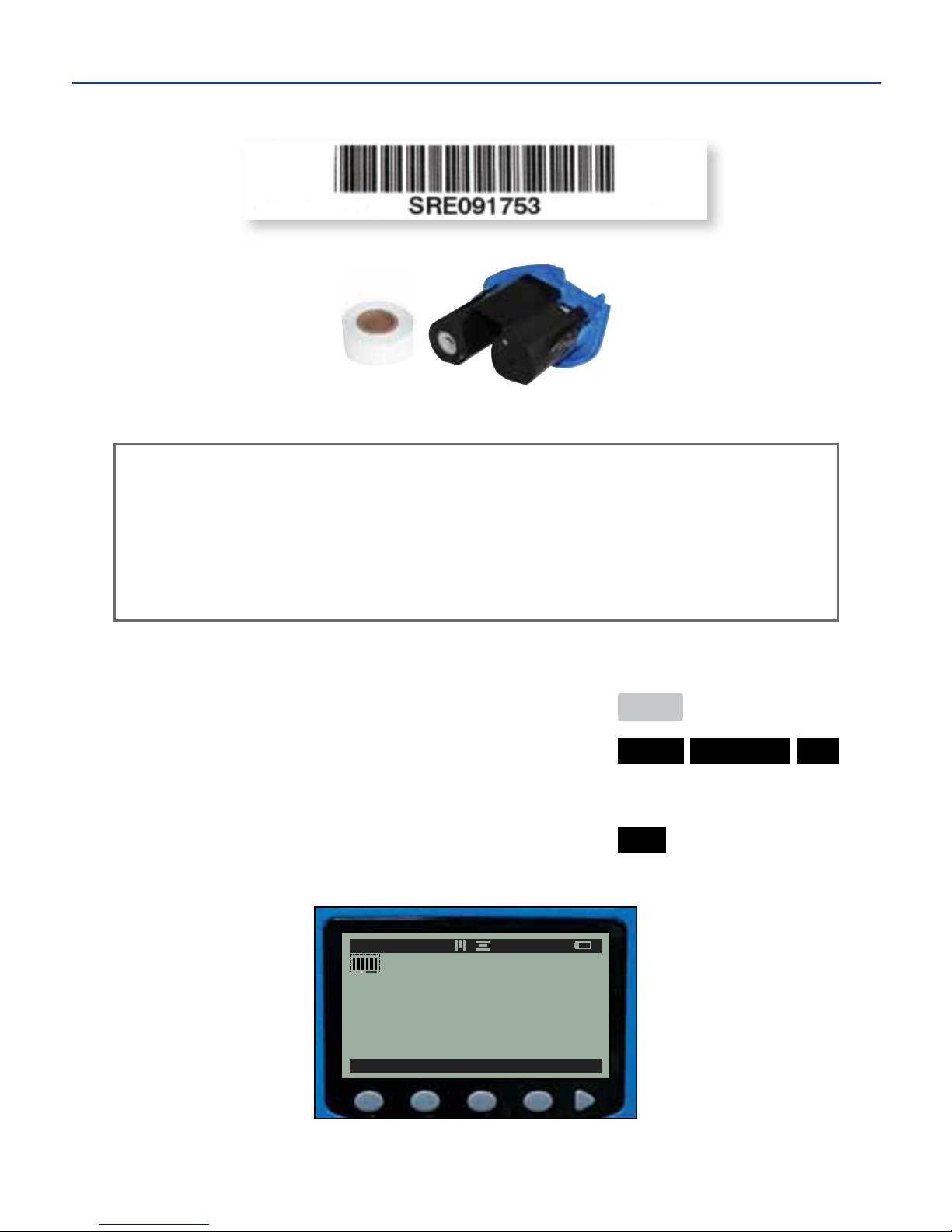
Example Label Directions #4: BAR CODE
Set Vertical Alignment
1. From the main menu ....................................................... MENU
2. Align the label vertically at the top ................................. ALIGN VERTICAL TOP
Insert Bar Code
3. Insert the bar code .......................................................... BAR
The bar code symbol appears on the edit screen:
4. Type the bar code data .................................................... SRE091753
7. EXAMPLE LABELS cont.
Finished Label
White ½" Standard Supply
and Black Ribbon Cartridge
This label’s features and settings:
One line of bar code, one line of text Auto-feed: ON
Unit of measurement: POINT CAPS Lock: ON
Auto-size: enabled(rstline)anddisabled (second line
Label alignment: HORIZONTAL - CENTER, VERTICAL - TOP.
FILE TEXT IMAGE
ALIGN >
A 37 AP 1/1
-39-
Page 43
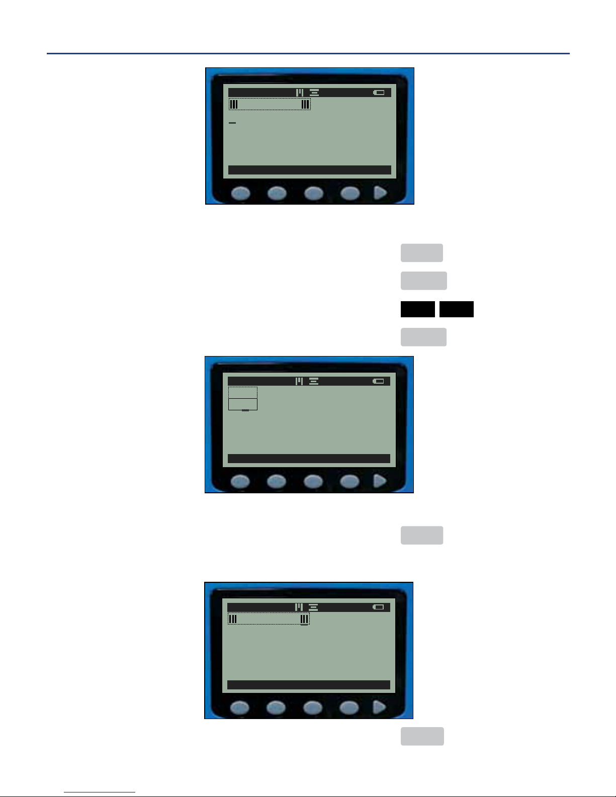
Enter Label Text
5. From the main menu ....................................................... MENU
6. Advance to the next line .................................................. ENTER
7. Change the text size to 10 point ..................................... TEXT SIZE 10
8.Registerthetextmodication ......................................... ENTER
uNOTE:Theauto-sizeindicator"A"isremovedforthesecondlinewhenthetextismanuallyentered.
9. Return to the main menu ................................................ MENU
10. Type the label text..........................................................SRE091753
11. Print the bar code label ................................................ PRINT
FILE TEXT IMAGE
ALIGN >
A 37 AP 1/1
SRE091753
FILE TEXT IMAGE
ALIGN >
A 10 P 2/2
SRE091753
AUTO UNITS
A 10 P 2/2
25A
10
-40-
Page 44

uIMPORTANT! Always turn OFF printer before cleaning or performing other maintenance.
The DuraLabel 2000 requires no lubrication and only minimal maintenance.
Basic cleaning of the exterior, the print head and the platen roller will prolong
the life of the printer and aid in producing crisp, clear labels with every print. An
instructional cleaning video on proper cleaning and maintenance of the printer
can be viewed online:
http://duralabel.com/duralabel-2000/dl2000-support.php
CLEANING EXTERIOR SURFACES
Use a damp cloth moistened with water and mild detergent solution, or use
commercial cleaner designed for electronic equipment, and wipe off any dust,
dirt or other visible markings.
CLEANING THE PRINT HEAD
1. Turn off the printer.
2. Open the printer cover by pulling down on the cover release lever.
3. Remove the supply spindle and ribbon cartridge to expose the print head. Do
not touch the print headwithngersorotherobjects.
4a. Using a cleaning pen, lightly place the tip of the pen onto the print head, and
rub back and forth several times to pull up any ribbon and ink particles. Repeat
this process if necessary.
4b. Using a cleaning card, insert one end of the card between the platen roller
and the black strip of the guideplate, pushing it through the slot at the top of the
printer cover. Place the other end of the card over the slotted round bar and down
into the compartment space so that the card lies between the slotted round bar
and the print head. Close the printer cover, turn the printer on, and press FEED.
4c. If no cleaning pen is available, the print head may be cleaned using a cotton
swab wetted with isopropyl alcohol in the same manner as described in step 4a.
5. Allow the alcohol to dry, then replace the ribbon cartridge and the loaded
supply spindle.Repeatasneeded,oraftereveryfourorverollsofsupply.
-41-
8. CLEANING & MAINTENANCE
Page 45
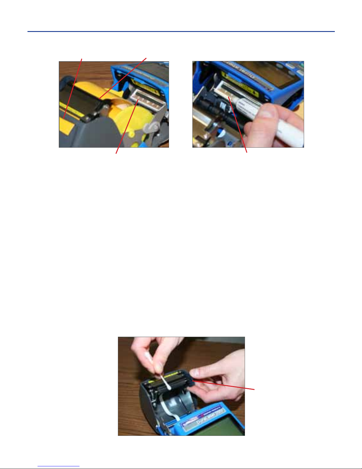
CLEANING THE PLATEN ROLLER
1. Turn off the printer.
2. Open the printer cover by pulling down on the cover release lever.
3. Remove supply spindle and ribbon cartridge to prevent cleaning solutions
from running on them. Be careful not to touch the print headwithngersor
other objects.
4. Using a cotton swab wetted with isopropyl alcohol, place the tip of the swab onto
the platen roller, and rub back and forth several times. Rotate the platen roller
wheel to expose other areas on the platen roller, and repeat the cleaning process.
5. Allow the alcohol to dry, then replace the ribbon cartridge and loaded supply
spindle.Repeatasneeded,oraftereveryfourorverollsofsupply.
-42-
8. CLEANING & MAINTENANCE cont.
Print Head Print Head (heat element is thin black line)
Platen Roller Wheel
Metal Guide Plate
and Platen RollerLabel Slot
Page 46

FCC NOTICE
This equipment has been tested and found to comply with the limits for a Class
B digital device, pursuant to Part 15 of the FCC Rules. These limits are designed
to provide reasonable protection against harmful interference in a residential
installation. This equipment generates, uses and can radiate radio frequency
energy and, if not installed and used in accordance with the instructions,
may cause harmful interference to radio communications. However, there is
no guarantee that interference will not occur in a particular installation. If this
equipment does cause harmful interference to radio or television reception, which
can be determined by turning the equipment off and on, the user is encouraged to
try to correct the interference by one or more of the following measures:
•Reorientorrelocatethereceivingantenna.
•Increasetheseparationbetweentheequipmentandreceiver.
•Connecttheequipmenttoanoutletonacircuitdifferentfromthattowhich
the receiver is connected.
•Consultthedealeroranexperiencedradio/televisiontechnicianforhelp.
Modicationsmadetotheprinter that are not approved by Graphic Products, Inc.
could be in violation of FCC regulations and void the user’s authority to operate
the equipment.
WARRANTY
Graphic Products, Inc., warrants to the customer that under normal use and
service the printer (with the exception of the print head) purchased, hereunder
shall be free from defects in material and workmanship for a period of one year,
from the date of shipment by Graphic Products, Inc. Expendable items or parts
such as labels and ribbons are not covered by this warranty. This warranty does
not cover equipment or parts that have been misused, altered, neglected, care-
lessly handled, or used for purposes other than those for which the printer was
manufactured. Thie warranty also does not cover loss, damages resulting from
accident, or damages resulting from unauthorized service.
-43-
9. COMPLIANCE & WARRANTY
Page 47

THERMAL PRINT HEAD
The warranty of the thermal print head is limited to one year from the date
of shipment to buyer. The warranty does not cover thermal print heads which
have been misused, altered, neglected, handled carelessly, or damaged due to
improper cleaning or unauthorized repairs.
WARRANTY SERVICE PROCEDURES
If defects should occur during the warranty period, the defective unit shall be
returned, freight and insurance prepaid, in the original shipping container to
Graphic Products, Inc. Include a contact name, action desired, and a description
of the problem and examples when possible. Graphic Products, Inc. shall not
be responsible for any loss or damages incurred during shipping. Any warranty
repairs to be performed by Graphic Products, Inc., shall be subject to said com-
pany’sconrmationthattheproductmeetswarrantyguidelinesintheeventofa
defect covered by its warranty.
GENERAL WARRANTY PROVISIONS
Graphic Products, Inc., makes no warranty as to the design, capability, capacity,
or suitability of any of its hardware, supplies or software. Software is licensed on
an “as is” basis without warranty. Except and to the extent expressly provided in
this warranty and in lieu of all other warranties, expressed or implied, including,
butnotlimitedtoanywarrantiesofmerchantabilityortnessforaparticular
product,purchasershallbesolelyresponsiblefortheselection,use,efciency
and suitability of Graphic Products’ products.
LIMITATION OF LIABILITY
In no event shall Graphic Products, Inc., be liable to purchaser for any indirect,
special,orconsequentialdamagesorlostprotsarisingoutoforrelatingto
Graphic Products’ products, or of the performance or a breach thereof, even if
Graphic Products, Inc., has been advised of the possibility thereof. Graphic Products’
liability, if any, to the purchaser or to the customers of purchaser hereunder shall
in no event exceed the total amounts paid to Graphic Products hereunder by the
purchaser for a defective product.
-44-
9. COMPLIANCE & WARRANTY cont.
Page 48

In no event shall Graphic Products, Inc., be liable to purchaser for any damages
resulting from or related to any failure or delay of Graphic Products in the
delivery or installation of the computer hardware, supplies, or software in the
performance of any services. The remedies set forth here are the sole and
exclusive remedies available to any person for any damages of any kind and
nature including incidental, consequential, or special, whether arising from
warranty (including implied warranties), contract, negligence, tort or otherwise.
In the event that any implied warranties (including but not limited to the implied
warrantiesofmerchantabilityandtnessforaparticularpurpose)arefoundto
exist, such warranties are limited in duration to their respective warranty periods.
-45-
9. COMPLIANCE & WARRANTY cont.
Page 49

SYMPTOMS & SOLUTIONS
Display Stays Blank/Black When the Printer is Turned ON
• Make sure the printerisoperatingwithintemperaturespecicationslistedin
this manual.
• If the printer has been recently transferred from one temperature environment
to another, there may be slight condensation on the circuit board. This will dis-
sipate in approximately 10 minutes. Allow the printer to equalize with current room
temperature before operating.
• Make sure the battery is fully charged and properly installed.
Printer Attempts to Print, But Supply Does Not Feed Out of Printer
• Ensure the supply has been loaded properly and is not jammed inside the printer.
• Make sure a ribbon cartridge is loaded into the printer and that the ribbon
cartridge is not empty.
• Make sure the supply spindle is not too tight (the supply should easily feed).
• Clean the platen roller as described in the manual.
• Make sure the battery is fully charged. A depleted battery might still run the
LCD but might not have enough power to print labels.
The Printer Cover Will Not Close
• Ensure the cover release lever is in the locked position.
• Make sure the loaded supply is going under the metal guide plate.
Printing Appears Uneven in Density and is Spotty or Blurred
• Clean the print head as described in the manual.
• Increase the heat settings.
Printed Characters Are Not Formed Properly
• Clean the platen roller.
• Recharge the battery.
• Clean the print head or adjust print density or motor speed.
• Make sure dust and foreign objects are not on the platen roller.
Printer Does Not Recognize Supply
• Make sure only Graphic Products’ supply is loaded in the printer.
• Make sure the supply has a bar code on the back of the liner.
-46-
10. TROUBLESHOOTING TIPS
Page 50

Printing Appears on One Side of Label Only
Make sure the printer cover is securely shut.
Diagonal Lines Appear in Text Due to Ribbon Wrinkle
1. Remove the ribbon cartridge
2. Tap on the blue portion of the ribbon cartridge while the black portion rests on
the table.
Or
3. Try a new cartridge.
Error Says Lithium Battery is Low
Contact Graphic Products for replacement options.
There is a Missing Line in the Printout in the Same Location on
Every Label
This indicates the print head pixels have been damaged in this area. The DuraLabel
2000 prints in landscape mode, so the missing line shows up throughout the entire
label. Replace the print head.
Printer Make a Grinding Noise When Attempting to Print
The clutch might need readjustment at the factory or might need to be replaced.
Faint Lines Appear On the Display
This primarily results in stress to the LCD and is caused by removing the battery
while the power is still ON. Always remove the battery when the power is OFF.
Lines should disappear within days.
-47-
10. TROUBLESHOOTING TIPS cont.
Page 51
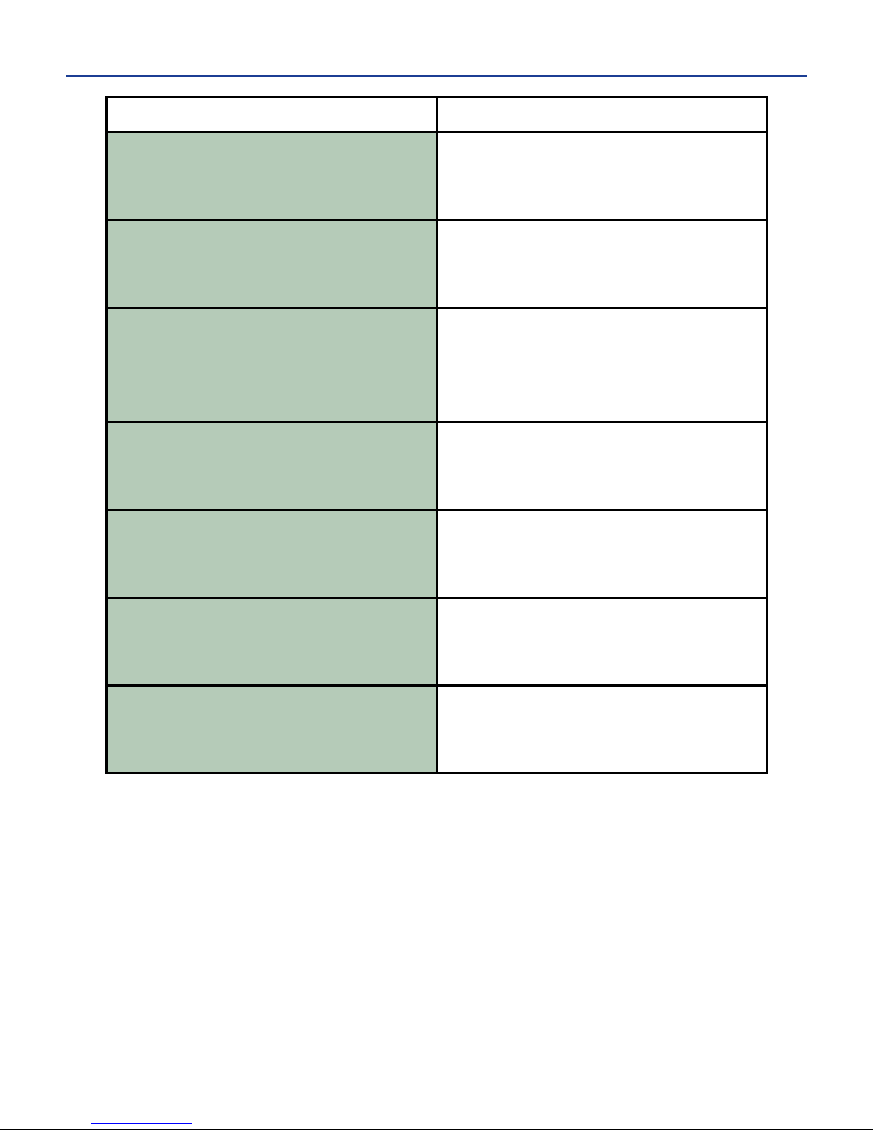
ERROR MESSAGES MEANING
Storage is full
The printer has reached the limit of possible
saved labels. To create space, delete unused
labelsasexplainedin"DeletingCurrentLabels"
section of this guide.
Value too large
No more room exists to add the desired character
to the label.
Not compatible with
current stock
The unit knows which supply is currently loaded
in the printer. If you try to retrieve a saved label
that was saved using a different supply size, this
error will alert you so that you cannot retrieve
that label until the proper size supply is loaded
in the printer.
Label design was
not stored
The label design was not stored due to the
memory being full or due to a canceled save.
Please close the cover
You must close the printer cover before printing.
Out of memory
You have reached the maximum number of lines
to a label.
Load label stock
The supply is not loaded in the printer, or the
printer cannot read the bar code on the back of
the supply.
-48-
10. TROUBLESHOOTING TIPS cont.
Page 52
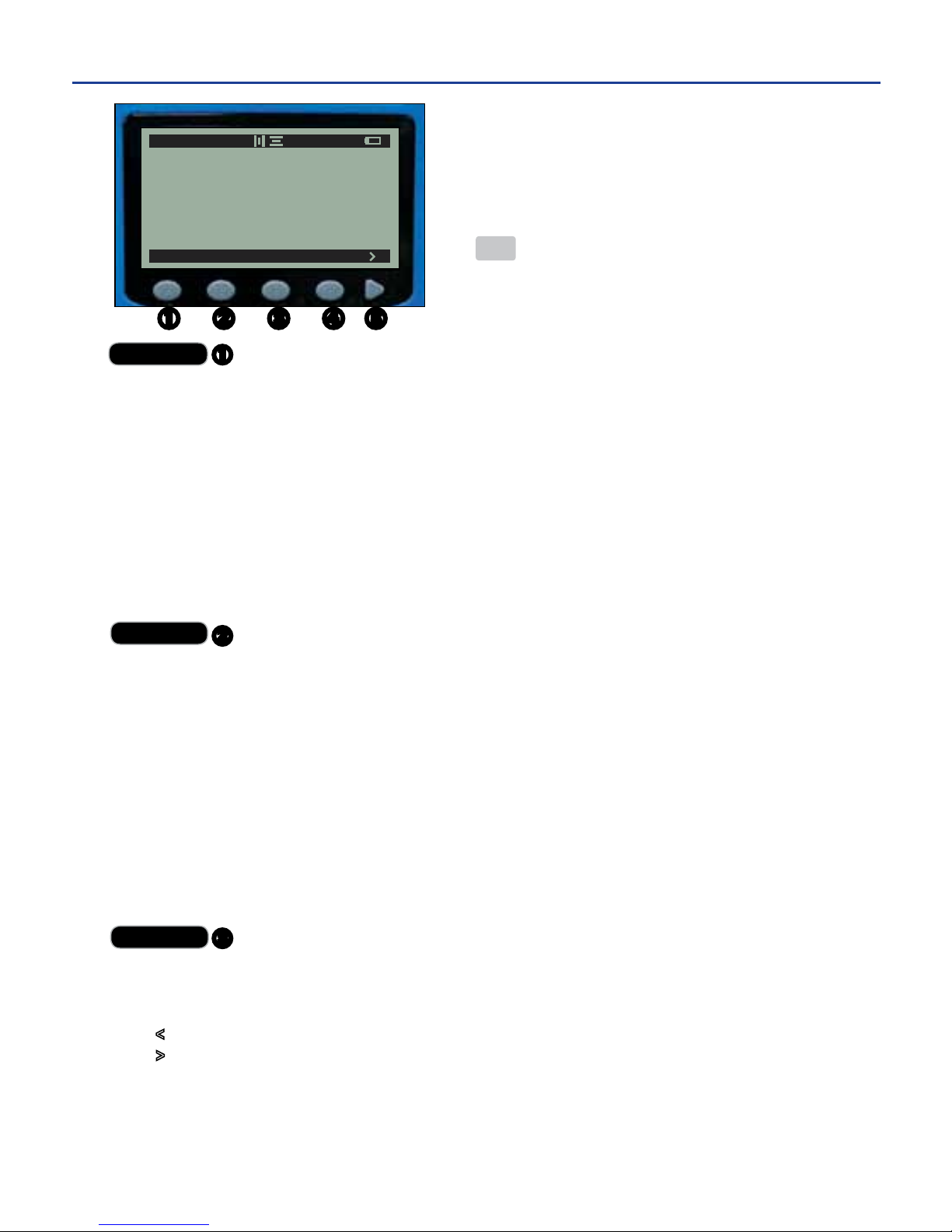
Soft Key
FILE – go to the save screen
NEW – begin new label design; return to default edit screen and soft key main menu
SAVE – save current label and return to the edit screen and soft key main menu
SAVE – save file name as entered and return to edit screen and soft key
main menu
DELETE – delete current label and return to the edit screen and soft key main menu
OPEN – open selected, previously saved label for further editing or printing
DELETE – delete selected label
DELETE – delete selected label and return to edit screen and soft key main menu
DEL ALL – delete all previously saved labels on the save screen
DELETE – confirm deletion of all previously saved labels on the save screen
Soft Key
TEXT – change text style attributes
SIZE – change text size
AUTO – enable/disable auto-size setting
UNITS – select unit of measurement (POINT, PERCENT, INCHES, MM) for each cell
POINT – format label using Point
PERCENT – format label using Percent
INCHES – format label using Inches
MM – format label using Millimeters
BOLD – toggle between bold and plain text style
ITAL – toggle between italics and plain text style
UNDER – toggle between underlined and plain text style
REV – reverse text/image and background color
Soft Key
IMAGE – select an image to include on label
FIND – enter the number associated with an image within the image library
SELECT – jump to the selected image on the image screen
< – return to previous page of images on the image screen
> – advance to next page of images on the image screen
SELECT – select highlighted image and return to edit screen and soft-key main menu
This tree-diagram shows the flow of menu
choices within the soft key menu system and
includes a brief description of each.
The ESC key returns the user to the previous
menu or screen.
12. SOFT KEY MENU SYSTEM
FILE TEXT IMAGE ALIGN
A 30 P 2/2
-49-
Page 53

Soft Key
ALIGN – change alignment of label
HORIZONTAL – align text/image(s) horizontally on label
LEFT – align text/image(s) on left side of label
CENTER – align text/image(s) in center of label
RIGHT – align text/image(s) on right side of label
VERTICAL – align text/image(s) vertically on label
TOP – align text/image(s) at top of label
CENTER – align text/image(s) in center of label
BOTTOM – align text/image(s) at bottom of label
Soft Key
> – scroll to next soft-key menu option (the BAR and SYSTEM soft keys)
BAR – create new cell on edit screen to input bar code data
BORDER – place border around text/image(s)
THIN – place thin border around text/image(s)
THICK – place thick border around text/image(s)
SYSTEM – enter system settings menu
DISP – view the current contrast setting for the LCD screen
< - increase the contrast of the LCD
> - decrease the contrast of the LCD
PRINT – adjust print settings
HEAT – adjust the heat of the print head
DEC – decrease the heat of the print head
INC – increase the heat of the print head
MOTOR – adjust advancement speed of label
DEC – decrease motor speed
INC – increase motor speed
FEED – adjust printer’s auto-feed setting
ON – turn on auto-feed
OFF – turn off auto-feed
TEST – verify printer is performing correctly
FEED – used for diagnostic purposes only
FORWARD – feeds supply forward
BI-DIR - feeds supply forward and then backward
TEST - print a test label showing print head heat results
PRINT VER – print a copy of printer info (serial, version, and
motor and heat settings) onto loaded supply
RESET – restore printer default settings
-50-
Page 54
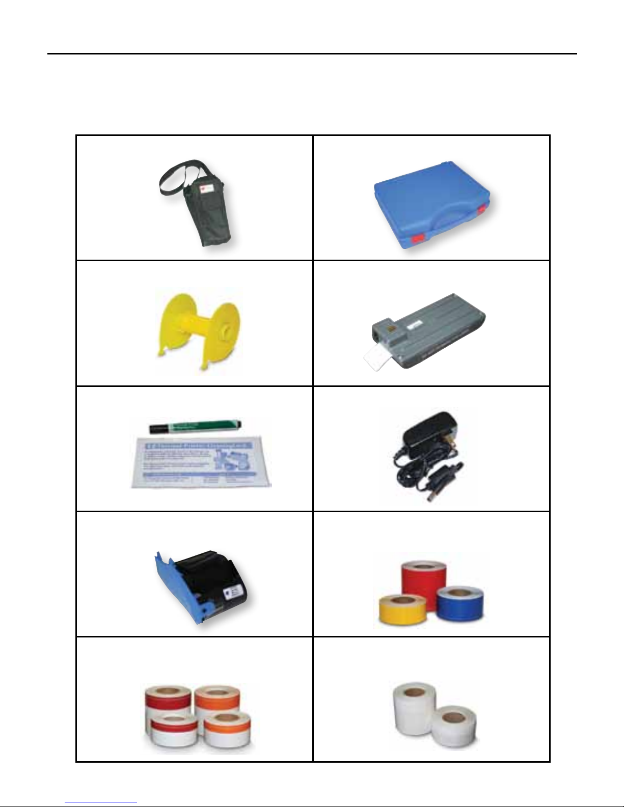
ACCESSORIES & SUPPLIES
To get the most out of your DuraLabel 2000 Handheld Label Printer, optional
accessories may be ordered upon request. Call Graphic Products at
1-800-788-5572 for details or visit www.duralabel.com
DL2000 Soft Case DL2000 Hardshell Case
Supply Spindle Rechargeable Battery
Cleaning Cards and Pen Battery Charger
Ribbon Cartridge - in white, red, blue,
yellow, green, and black.
Premium Supply Tape - in 1/2", 1" and
2" rolls in white, red, blue, yellow, green,
orange, black, and clear.
Two-Color Premium Supply Tape - in 1"
and 2" rolls, white, with pre-printed red
and orange stripes.
Self-Laminating Wire Wraps - in 2" x 1/2"
and 1" x 1/4" rolls in white, red, blue,
yellow, green, orange, and magenta.
-51-
Page 55

NOTES
-52-
Page 56

www.DuraLabel.com
© 2009, 2010, Graphic Products, Inc. All Rights Reserved
1-800-788-5572
P.O. Box 4030
Beaverton, OR 97076
Version 2.5
 Loading...