

Grape Solar GS-MPPT-60, GS-MPPT-45 User Manual
Grape Solar MPPT-45
Solar charge controller
User Manual
Specification:
Model
GS-MPPT-45
GS-MPPT-60
Battery voltage
12V/24V/36V/48V
12V/24V/36V/48V
Charging current
45A
60A
Max. voltage of solar panel
array
150V
Dear users:
Thank you very much for choosing our products!
Please read the manual carefully before using our controllers.
Catalog
1. Safety Attention: ......................................................................................................................................................................... 3
2. Features: ...................................................................................................................................................................................... 3
3.Charging introduction. ................................................................................................................................................................. 4
4.Connection. .................................................................................................................................................................................. 5
1. For one machine operation: ............................................................................................................................................ 5
2. For parallel operation: ..................................................................................................................................................... 5
5. Panel introduction. ..................................................................................................................................................................... 6
A. Fix the hooks. .................................................................................................................................................................. 6
B. Charging indication. ........................................................................................................................................................ 6
C. Battery indication. .......................................................................................................................................................... 7
D. Cooling fin. ...................................................................................................................................................................... 7
E-H. LCD display and keys operation. ..................................................................................................................................... 7
6.Instructions. ............................................................................................................................................................................... 10
7. Networking introduction. ......................................................................................................................................................... 10
...........................................................................................................................................................................................................
8. Installation instructions. ........................................................................................................................................................... 11
9. Environmental requirements. .................................................................................................................................................. 12
10. Protections. ............................................................................................................................................................................. 12
11.Fault code. ................................................................................................................................................................................ 13
12. Parameters. ............................................................................................................................................................................. 14
13. Conversion efficiency .............................................................................................................................................................. 16
1、12V system ....................................................................................................................................................................... 16
2、24V system ....................................................................................................................................................................... 16
3、48V system ....................................................................................................................................................................... 17
14. Dimension. .................................................................................................................................. Error! Bookmark not defined.
1,Dimension of MPPT-45 ........................................................................................................... Error! Bookmark not defined.
2,Dimension of MPPT-60 ....................................................................................................................................................... 17
1. Safety Attention:
The input voltage is high, so please read the instructions before operation and please do not operate the controller before
training.
1. Warning: The operation is dangerous; please observe proper safety precautions before operation.
2. Attention: The operation can damage or destroy equipment.
3. Reminder: Suggestions and hints to the operator.
2. Features:
1. Can be used in all kinds of environments.
2. Double crest or multi crest tracing technique design, when the solar panel is under shadow or part of the solar panel is
damaged, multi crest will turn up the voltage in the I-V curve, and the controller can still trace the Maximum Power Point.
3. Built-in maximum power point tracking algorithm which promotes energy utilization efficiency of the PV system. The
charging efficiency is 15%~20% higher than PWM mode.
4. Adopting tracking algorithms to track the best working point on the I-V curve promptly and accurately within 15 seconds,
the MPPT efficiency can reach 99.9%.
5. With the use of advanced digital power technology, circuit energy conversion efficiency is as high as 96%
6. Four stage charging order mode: MPPT-equalizing charging-boost charging-float charging.
7. With current-limiting charging mode, when the power of solar panel is over-sized and charging current exceeds the rated
current, the controller will lower the charging power, which enables the system to work under the rated charging current.
8. The controller can network with additional controllers using the linked telecommunication cable.
9. Fault code indication helps users confirm the system fault.
10. 12V/24V/36V/48V auto identified.
11. Supports data storage, the storage span can reach 5 years.
12. Controller has built-in LCD screen monitoring, and the controller parameters are adjustable.
13. Built-in temperature sensor, when the temperature exceeds the set value, the charging current will decrease, followed by
the decrease of temperature, so as to control the controller’s temperature rise.
14. Temperature compensation function adjusts the charge and discharge parameters automatically, which can improve
battery service life.
15. Various system protection functions including over-charge, over-discharge, over-load, over-heat, the battery reverse
connection protection and so on.
16. TVS lighting protection.
3.Charging introduction.
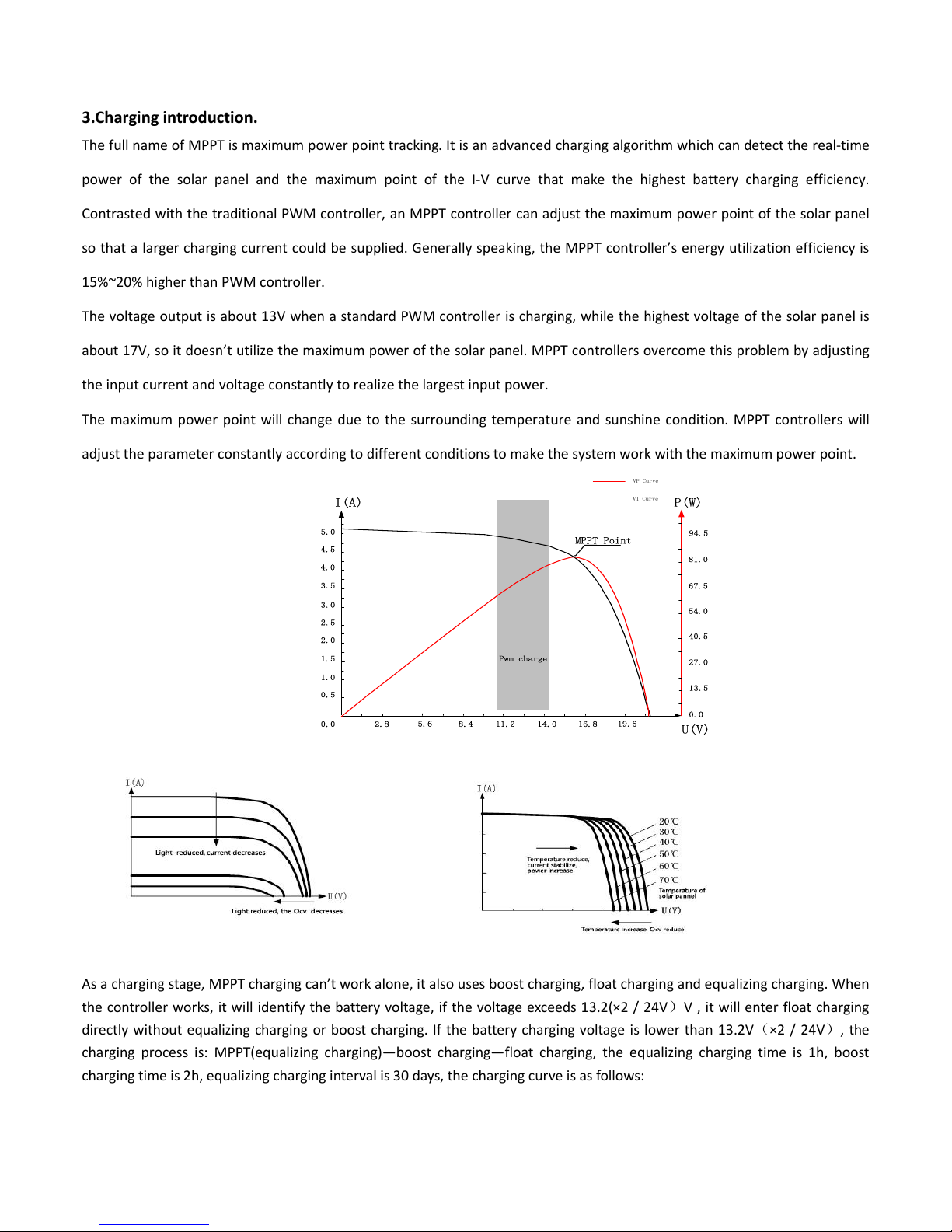
The full name of MPPT is maximum power point tracking. It is an advanced charging algorithm which can detect the real-time
power of the solar panel and the maximum point of the I-V curve that make the highest battery charging efficiency.
Contrasted with the traditional PWM controller, an MPPT controller can adjust the maximum power point of the solar panel
so that a larger charging current could be supplied. Generally speaking, the MPPT controller’s energy utilization efficiency is
15%~20% higher than PWM controller.
The voltage output is about 13V when a standard PWM controller is charging, while the highest voltage of the solar panel is
about 17V, so it doesn’t utilize the maximum power of the solar panel. MPPT controllers overcome this problem by adjusting
the input current and voltage constantly to realize the largest input power.
The maximum power point will change due to the surrounding temperature and sunshine condition. MPPT controllers will
adjust the parameter constantly according to different conditions to make the system work with the maximum power point.
Pwm charge
U(V)
I(A) P(W)
VP Curve
VI Curve
94.5
81.0
67.5
54.0
27.0
40.5
13.5
0.0
19.6
16.814.011.28.4
5.6
2.80.0
0.5
1.0
1.5
2.0
2.5
3.0
3.5
4.0
4.5
5.0
MPPT Point
As a charging stage, MPPT charging can’t work alone, it also uses boost charging, float charging and equalizing charging. When
the controller works, it will identify the battery voltage, if the voltage exceeds 13.2(×2 / 24V)V , it will enter float charging
directly without equalizing charging or boost charging. If the battery charging voltage is lower than 13.2V(×2 / 24V), the
charging process is: MPPT(equalizing charging)—boost charging—float charging, the equalizing charging time is 1h, boost
charging time is 2h, equalizing charging interval is 30 days, the charging curve is as follows:
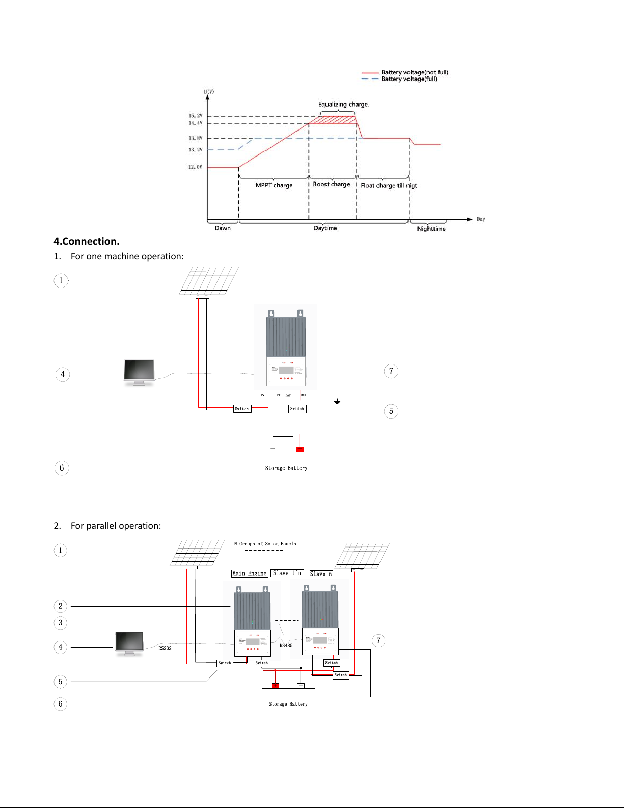
4.Connection.
1. For one machine operation:
Storage Battery
+-
+ -
PV+ PV-
BAT-
BAT+
6
4
1
7
5
Switch
Switch
2. For parallel operation:
RS485
Storage Battery
+ -
N Groups of Solar Panels
+ -
+ -
Main Engine
Slave n
Slave 1~n
RS232
1
2
3
4
5
6
7
Switch Switch
Switch
Switch
1---Solar panel.
The power for battery charging.
2---Controller.
Central nervous system, which controls the overall system.
3---RS485 Telecommunication cable.
Communication line of the controller which is necessary for parallel operation.
4---Open space.
It can insure the safety of operators (the switching element is optional).
5---Battery.
A battery pack which is composed of batteries in series, parallel, or a combination.
6---LCD display.
The LCD can display the system status, parameters, records and the set value. (You can just choose one communication way:
PC or LCD).
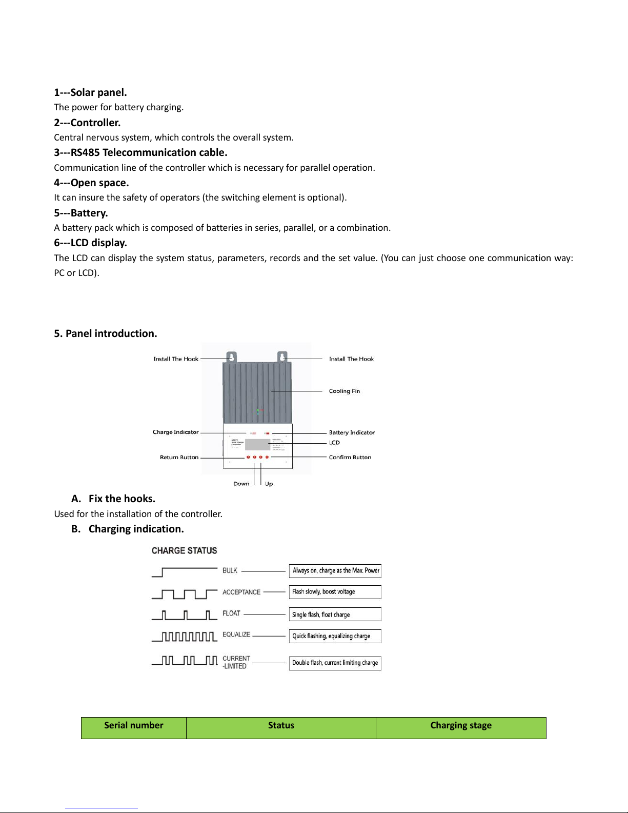
5. Panel introduction.
A. Fix the hooks.
Used for the installation of the controller.
B. Charging indication.
Serial number
Status
Charging stage
 Loading...