

Page 1
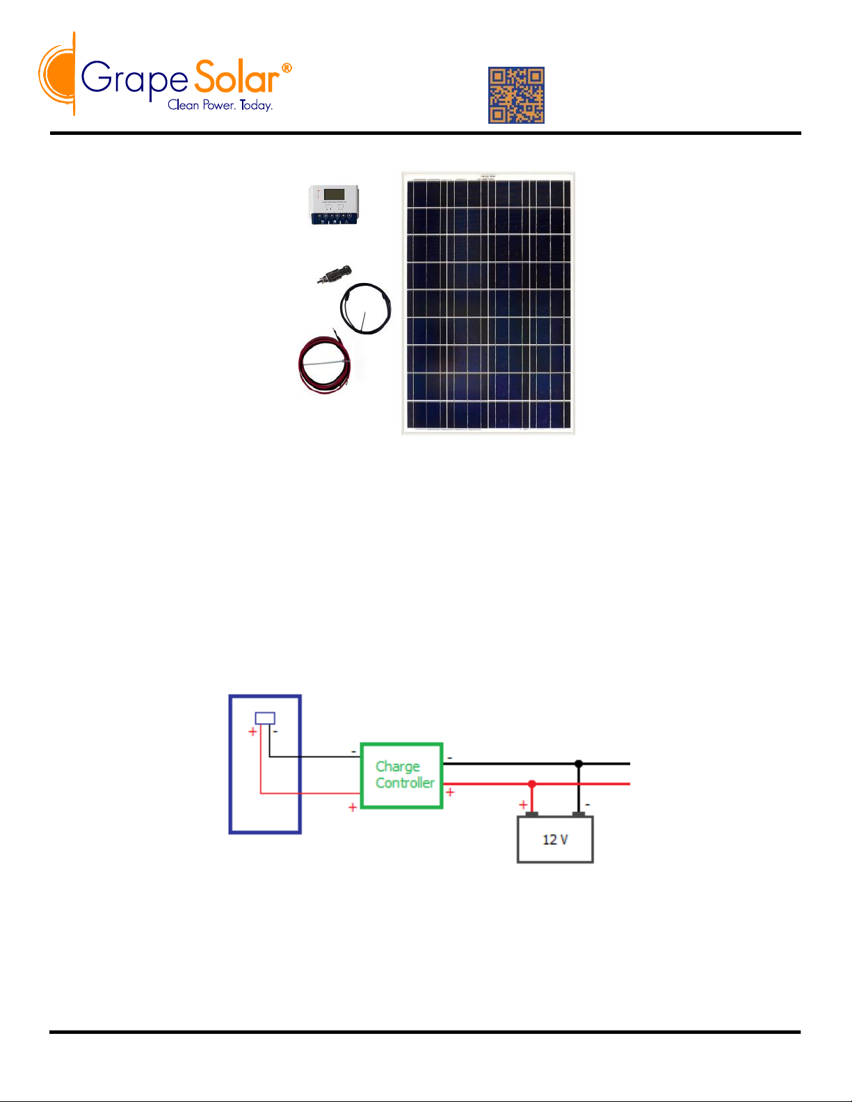
Grape Solar 100 Watt Off Grid Kit
(GS-100-KIT)
Installation Guide
IMPORTANT: Please read the GS-PWM-COMET-40 Owner’s Manual and the
Panel User Guide (included with panels) before assembling this kit.
www.grapesolar.com
Tel. 1-877-264-1014 (toll free), 1-541-349-9000, Fax: 1-541-343-9000
1
©Copyright 2016, Grape Solar, Inc. All Rights Reserved
For additional information about this kit visit grapesolar.com/manuals.html, or email [email protected]
GS-100+KIT EXPANDABLE PHOTOVOLTAIC
POWER GENERATION SYSTEM
CONFIGURATION MANUAL Rev. 180601
Valid from June 2018
Required tools: Philips-head screwdriver
Recommended tools: insulated wrench or other insulated tool for battery connections, digital multimeter or voltmeter
Basic Wiring Diagram
Page 2
www.grapesolar.com
Tel. 1-877-264-1014 (toll free), 1-541-349-9000, Fax: 1-541-343-9000
2
Installation Guide
Valid from June 2018
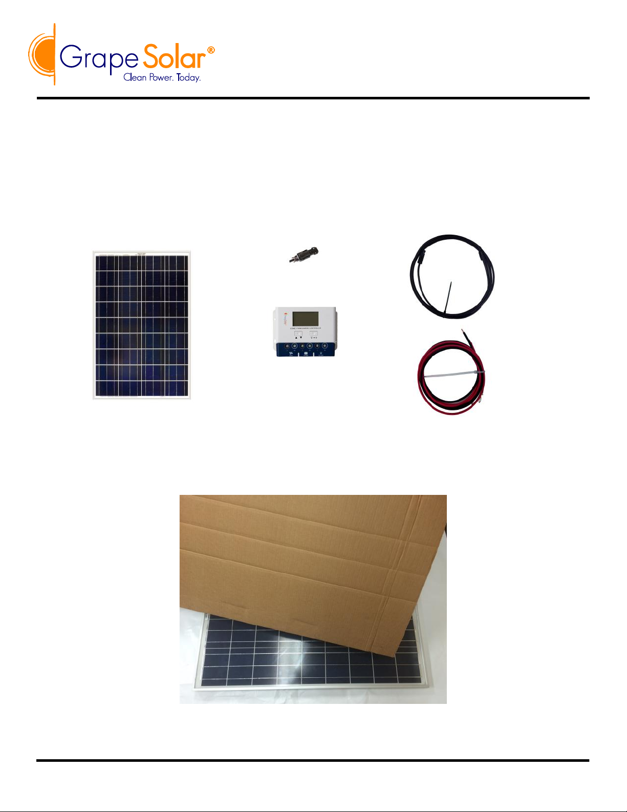
Step 1: Check your order to make sure that all parts are included. For the 100 watt kit, this is a GS -
STAR-100 solar panel, one 10 amp inline fuse, a 15-foot MC4 cable (cut this in half, the two
halves connect the panel leads to the charge controller’s solar inputs), a red/black 5-foot barewire-to-ring-lug cable pair (charge controller to battery), and a GS-PWM-COMET-40 charge
controller.
Step 2: If you are connecting the system during daylight, cover the panel with cardboard, cloth, or a
similar option so that it does not output power. Place the panel so it is facing due south at ap-
proximately the same angle as your latitude, in full sun.
GS-100+KIT EXPANDABLE PHOTOVOLTAIC
POWER GENERATION SYSTEM
CONFIGURATION MANUAL Rev. 180601
Page 3
www.grapesolar.com
Tel. 1-877-264-1014 (toll free), 1-541-349-9000, Fax: 1-541-343-9000
3
Valid from June 2018
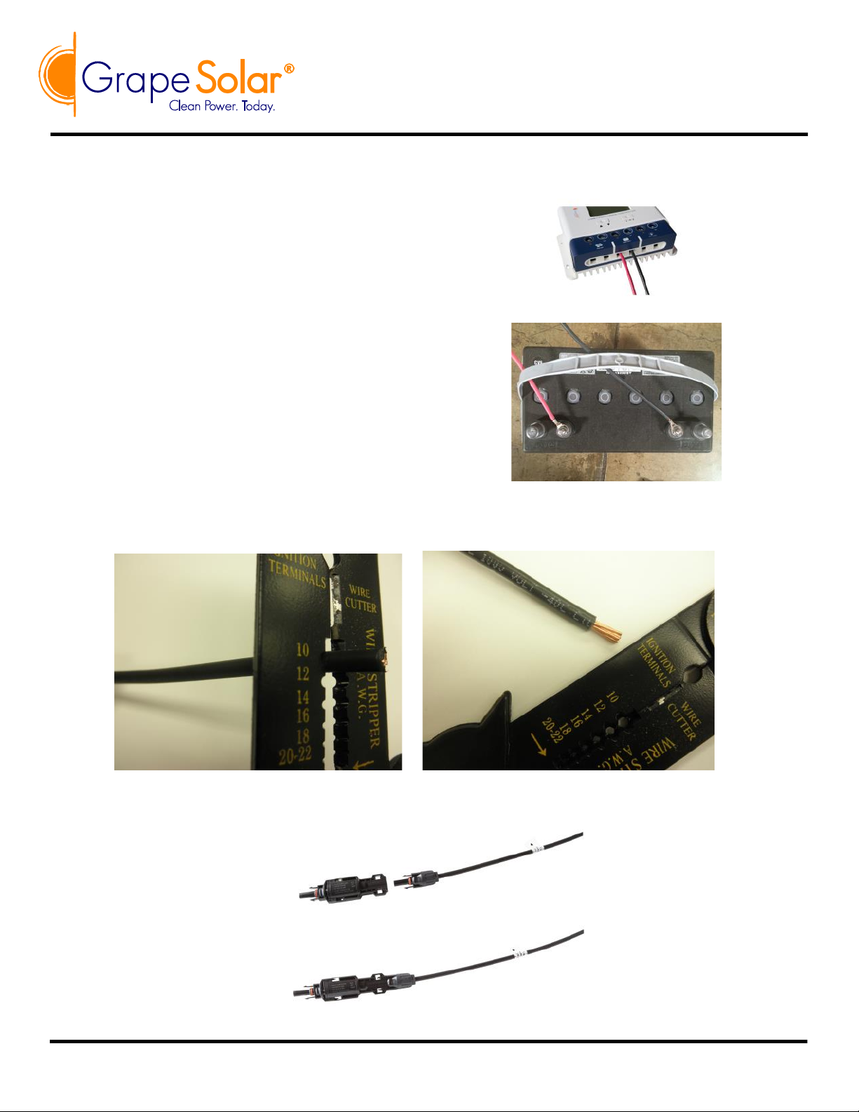
Step 4: Use the 5-foot red & black cable pair to
connect your positive and negative battery termi-
nals to the “Battery Positive” (use red cable from
the positive battery terminal) and “Battery Negative” (use black cable from the negative battery
terminal) inputs of the charge controller (the cen-
ter set of terminals).
Step 3: Mount controller if desired (note that it must be in a NEMA-4 rated enclosure if it is outdoors).
GS-100+KIT EXPANDABLE PHOTOVOLTAIC
POWER GENERATION SYSTEM
CONFIGURATION MANUAL Rev. 180601
If your battery has sufficient charge (11.5 volts or more),
you should now see the controller’s LCD display activate.
This means the controller has power (controllers are pow-
ered by the battery, not the panels).
Step 5: Cut the 15-foot MC4 cable in half using wire cutters, stripping back the bare ends around 1/4”.
Label the positive lead with tape to avoid polarity mismatch.
Step 6: Connect the positive MC4 output of the panel to the 10 amp inline fuse, as shown below:
Page 4
www.grapesolar.com
Tel. 1-877-264-1014 (toll free), 1-541-349-9000, Fax: 1-541-343-9000
4
Exclusion for Documentation
UNLESS SPECIFICALLY AGREED TO IN WRITING, SELLER
MAKES NO WARRANTY AS TO THE ACCURACY, SUFFICIENCY, OR SUITABILITY OF ANY TECH-
NICAL OR OTHER INFORMATION PROVIDED IN ITS MANUALS OR OTHER DOCUMENTATION;
ASSUMES NO RESPONSIBILITY OR LIABILITY FOR LOSSES, DAMAGES, COSTS OR EXPENSES,
WHETHER SPECIAL, INDIRECT, CONSEQUENTIAL OR INDIDENTAL, WHICH MIGHT ARISE OUT OF
THE USE OF SUCH INFORMATION. THE USE OF ANY SUCH INFORMATION WILL BE ENTIRELY AT
THE USER’S RISK; AND
REMINDS YOU THAT IF THIS MANUAL IS IN ANY LANGUAGE OTHER THAN ENGLISH, ALTHOUGH
STEPS HAVE BEEN TAKEN TO MAINTAIN THE ACCURACY OF THE TRANSLATION, THE ACCURACY CANNOT BE GUARANTEED. APPROVED CONTENT IS CONTAINED WITH THE ENGLISH LAN-
GUAGE VERSION WHICH IS POSTED AT WWW.GRAPESOLAR.COM/MANUALS.HTML
Important: Installations of this kind must be certified/approved as “code-compliant” to the national and lo-
cal building and electrical codes. Installers should have adequate knowledge of national and local code to
ensure the installation passes inspection by the local electric authority.
Important: Proper fuses or breakers should be used to comply with all local and national codes. Contact
Grape Solar for specific recommendations.
Important: All batteries used for this system should be identical. Do not mix battery types or sizes. Do not
mix old batteries with new batteries. Performance and charging anomalies can occur if types, sizes, or age
of batteries are not identical.
Valid from June 2018
Step 8: Uncover the panel — you should see the icon on the upper left of the controller display change from a
moon to a sun after this is done. As time passes, you should the battery charge increase, until the controller
is in “Float” mode (NOTE: time to reach Float will vary depending on many factors including weather, location, time of year, and battery capacity). Once in Float mode, the battery can be used to provide power. It
is best practice to ensure that the battery bank reaches Float at least once per week.
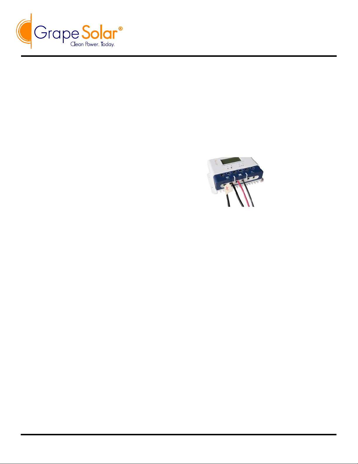
Step 7: Connect the bare wire end of the (previously
marked) positive cable to the “PV Positive” input
of the controller, and the negative cable end to the
“PV Negative” input (the left set of terminals).
GS-100+KIT EXPANDABLE PHOTOVOLTAIC
POWER GENERATION SYSTEM
CONFIGURATION MANUAL Rev. 180601
Then connect the fused positive output and the negative panel
cable output to the previously cut MC4-to-bare wire pair.
 Loading...