

Granudos 25-S4, 45-S4, 100-S4 Operating Instructions Manual

WDT Operating Instruction GRANUDOS 25/45/100 (S41C-06/12) page 1 of 27
Series No..........................Customer..........................................Date of delivery……….……………
Operating instructions GRANUDOS 45/100-S4
Safety Devices
1. Chlorine and acid may not be mixed together
or with other chemicals
Pay attention to the safety devices on
chemical containers
2. The dosing hopper must be screwed even
and firmly to the container
3. Ensure after changing a drum, that it is firmly
fixed in position and the securing systems are
used
4. In service the dissolving system must be
covered with the supplied cover
5. Only instructed personnel may work with the
GRANUDOS
6. Ensure booster pump does not run dry,
always isolate pump when backwashing.

WDT Operating Instruction GRANUDOS 25/45/100 (S41C-06/12) page 2 of 27
Commissioning Form for GRANUDOS-S4
Please see hereto § 4 Commissioning
GRANUDOS-Type:.....................year:...................ser.no................................
Commissioning undertaken by.............................sign…….............................
Sign of operator:...........................................................................................
Objekt:.................................................................date..................................
1. Dissolving system (
1.1 Adjust pressure switch: see § 4.3 [ ]
1.2 Check pressure switch: close inlet ball valve– L2 burns, GR stopp [ ]
1.3 Check flow switch: close outlet ball valve - dos. off, L1 burns [ ]
1.4 Check level switch: switch body up - dos. off, L1 burns [ ]
1.5 Check level switch: switch body down - GR stopps, L2 burns [ ]
1.6 Adjust water level: – adjust washer to pressure conditions [ ]
1.7 Check function of floating valve: water flow reacts smoothly [ ]
2. Dosing unit chlorine
2.1 Function heating nozzle: dosing tube warm [ ]
2.2 Function empty switch: turn drum – L4 burns [ ]
2.3 Function dosing motor: programme „test chlorine“ – chlorine dosed [ ]
2.4 check clamp bands and safety belt [ ]
2.5 introduction to drum change § 4.6 [ ]
3. Dosing unit pH-correction
3.1 Function empty switch: take suction lance out of container – L3 burns [ ]
3.2 Function dosing pump: programm “test acid” – acid is suct up [ ]
4. Control unit – after opening of the housing
4.1 check all push connectors: well pushed in [ ]
4.2 External control: auto-controller on „Manual“ – chlorine doses [ ]
4.3 External control: auto-controller on „Manual“ – acid doses [ ]
4.4 External control: check any linked switch off [ ]
5. Other jobs
5.1 Clean GRANUDOS thoroughly [ ]
5.2 Clean environement of GRANUDOS thoroughly [ ]
5.3 Operation instructions discussed and handed to the operator [ ]
at switches note 6 seconds delay!)
No warranty without fully signed commissioning form!

WDT Operating Instruction GRANUDOS 25/45/100 (S41C-06/12) page 3 of 27
TABLE OF CONTENTS
Test certification: - loose insert Main Safety devices 1
Commissioning form 2
page
1. Notes to this manual................................................................................................................... 4
1.1 What does that manual desrcibe .................................................................................................... 4
1.2 Target group .................................................................................................................................... 4
1.3 Safekeeping of the manual .............................................................................................................. 4
1.4 Intended use .................................................................................................................................... 4
1.5 Safety notice/used symbols:............................................................................................................ 4
2. Technical Description ........................................................................................................... 6
2.1 Technical Data .................................................................................................................................. 6
2.2 The Drum Carrier ......................................................................................................................... 7
2.3 Chlorine Dosing Assembly ................................................................................................................ 7
2.4 Acid Dosing ....................................................................................................................................... 8
2.5 Dissolving System ............................................................................................................................. 8
2.6 Control System with program GR S41 .............................................................................................. 9
2.6.1 Operation elements .................................................................................................................... 9
2.6.2 Operation and Test Programmes............................................................................................. 10
2.6.3 Dosing Performance - Dosing scheme ...................................................................................... 11
2.6.4 Diagnosis by LED indication ...................................................................................................... 12
2.6.5 Irritations not indicated by monitoring switches .................................................................... 14
2.7 Filter disinfection at back wash – high chlorination ...................................................................... 15
3. Installation ......................................................................................................................... 16
3.1 Placing of the GRANUDOS in the pool technique room ................................................................ 16
3.2 Installation to the pool circulation ................................................................................................. 16
3.3 Electrical connection ...................................................................................................................... 17
3.4 Fitting the acid pump roller/tube .................................................................................................. 17
4. Taking into operation .......................................................................................................... 18
4.1 Check of pump .............................................................................................................................. 19
4. 2 Deaeration of the water supply tubing ......................................................................................... 19
4.3 Adjusting the pressure switch ........................................................................................................ 19
4.4 Water flow/Suction performance of the venturi .......................................................................... 19
4.5 Water level in the flushing tank .................................................................................................... 20
4.6 Loading the Drum onto the Machine (25-50 kg plastic drum - ret. sketch p. 3) ...................... 20
4.7 Providing of acid ............................................................................................................................. 21
4.8. Adjusting the dosing performance of GRANUDOS – continuous dosing ..................................... 21
4.9 Dosing Controlled by Auto-Controller ........................................................................................... 22
5. Maintenance ....................................................................................................................... 23
6. Control board S41c - wiring - fuses ....................................................................................... 24
7. Spare Parts GRANUDOS 45/100-S4 ...................................................................................... 25
8 . Maintenance List GRANUDOS 10/45/100 ............................................................................. 26
9. Wiring diagram ................................................................................................................... 27
WDT Operating Instruction GRANUDOS 25/45/100 (S41C-06/12) page 4 of 27
Danger!
Attention!
Note!
Corrosive!
Attention
: any works at the electrical parts of
the machine may only be
1. Notes to this manual
1.1 What does that manual desrcibe
That manual describe installation, commissioning and operating of the machine.
1.2 Target group
Only people advised in the function are allowed to operate the machine. The mounting of the machine
may only be executed by skilled workers.
1.3 Safekeeping of the manual
All operation manuals are to be safekept for direct use nearby the machine.
1.4 Intended use
The machine is only allowed to be used in the intended purpose. There is no implied warranty for
other use than the intended one.
1.5 Safety notice/used symbols:
Under this sign any real fact is described that could lead to personal injury if
not regarded.
Under this sign any real fact is described that could lead to material damages
if not regarded.
Under this sign any real fact is described that could lead to improvement of
your process if regarded.
Under this sign any real fact is described that could lead to personal injury or
material damages if not regarded.
executed by skilled workers. Electrical parts must be switched off.
If irritations at the electrical supply do occur, switch off the machine
immediately.
Fuses are only to be exchange through original ones with the same
strength.
WDT Operating Instruction GRANUDOS 25/45/100 (S41C-06/12) page 5 of 27
Waste disposal
Mandatory sign:
Mandatory sign:
Mandatory sign:
Note:
The operator is responsable for the disposal in conformity to the national
regulations.
Use eyes protection
Use face protection
Use protection gloves
WDT Operating Instruction GRANUDOS 25/45/100 (S41C-06/12) page 6 of 27
11
9
drum carrier
2. Technical Description
2.1 Technical Data
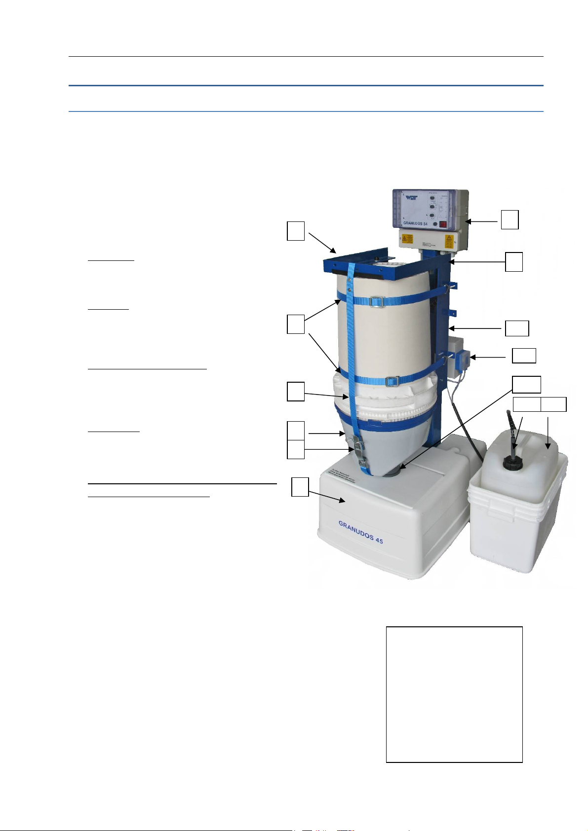
The GRANUDOS 45/100-S4 dosing system comprises:
- main vertical support with rotating drum carrier
- dosing assembly for calcium hypochlorite granules
- acid dosing equipment
- dissolving system
- microprocessor control panel
1
7
measures:
space needed: 60 x 150 cm
height: 140 cm
weight: 50 kg
material:
main vertical support and drum carrier:
steel, powder coated
2
other parts: PVC, PE
GRANUDOS booster pump(if installed)
centrifugal pump: 0,3 kW, 230 VAC,
supply pressure: >0,2 bar (20 kPa)
3
fresh water supply. >2 bar (200 kPa)
water flow: app. 1000 l/h
4
5
Dosing performance with 2 dosing motors
see para “control system”:
6
chlorine: GR45 mot 35 rpm app. 2.4 * ( 0,44**) kg/h
GR100 mot 60 rpm app. 4,0 * ( 0,7 **) kg/h
acid: 3,0* ( 0,5 **) l/h
* cycle time 1 minute
** cycle time 6 minutes
Chlorine dosing performance depends on chlorine
quality and is affected by too fine or too coarse
or humid product. Acid dosing performance is given in litres
per hour. It is recommended to use sulphuric acid 37%.
1
2 2 clamp bands
3 belts for fasten drum
4 dosing hoper
5 locker for safety belt
6 dissolving system
7 controlsystem
8 type label (not seen)
9 locker for drum carrier
10 acid pump
11 dust protection tube
12 acid carboy lance
13 acid container with tub
8
WDT Operating Instruction GRANUDOS 25/45/100 (S41C-06/12) page 7 of 27
2.2 The Drum Carrier
The rotating drum carrier assembly (6) is fixed to the main vertical support (10). The drum
(1) with chlorine is fixed on the carrier assembly (6) by 2 band clamps (2) and a retaining belt.
The dosing hopper (3) is fixed on the drum in place of the drum lid. The carrier with the drum is
then turned through 180° to the dosing position, the chemical is dosed into the dissolving
system (5) where it is fully dissolved and conveyed by a venturi to the buffer tank.
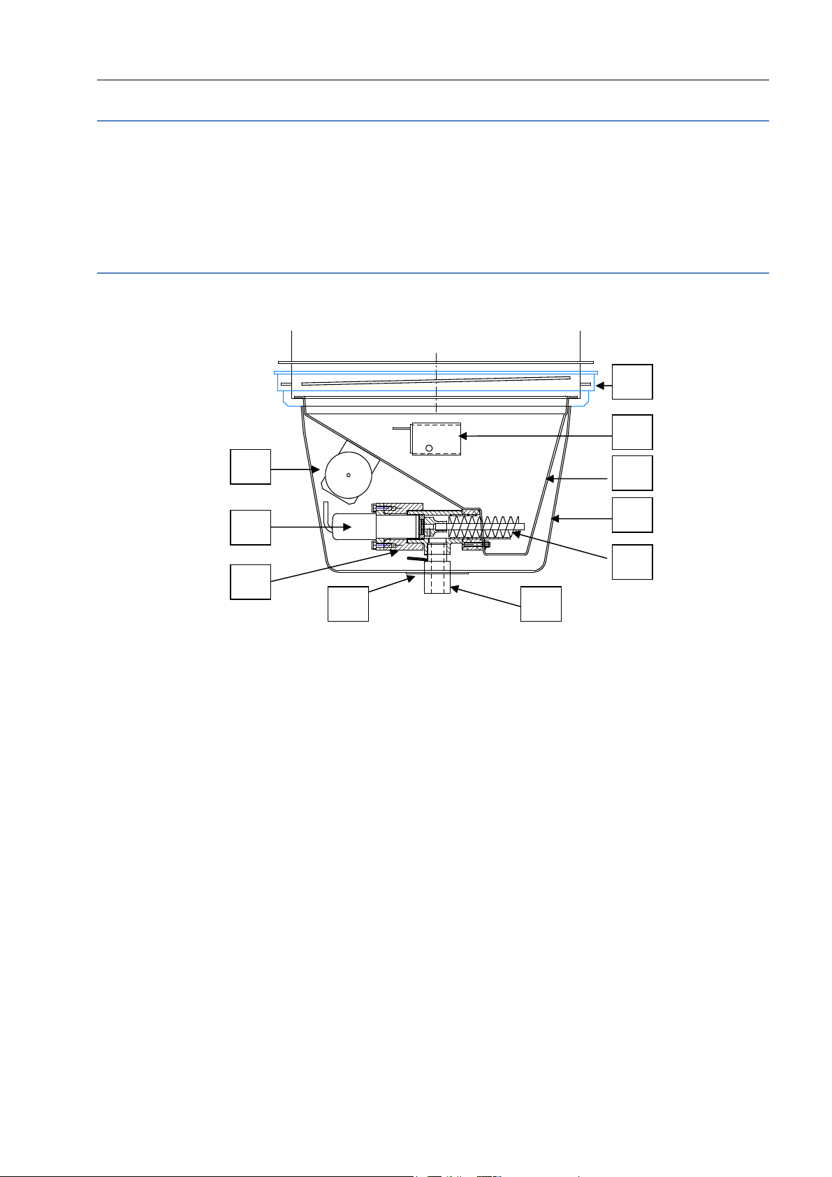
2.3 Chlorine Dosing Assembly
19
17
15
10
11
13
14 18
16
12
10 dosing hopper 16 hopper cover
11 dosing motor 17 knocker
12 dosing screw 18 seal washer
13 motor mounting 19 dosing hopper screw ring
14 dosing nozzle heated
15 drum empty switch with adjusting screw and LED
The dosing screw (12) meters the chlorine through the heated dosing nozzle (14) to the dissolving
system. If the drum empty switch (15) is indicating, app 1 kg chlorine is left in the hopper. The knocker
(17) gives a hit to the hopper wall at each dosing motor run cycle so supporting flowing of the granules.
Dosing performance is adjusted by the switch 4 at front fascia, see para "Start up operation".
WDT Operating Instruction GRANUDOS 25/45/100 (S41C-06/12) page 8 of 27
2.4 Acid Dosing
The acid required for pH-control is metered by the peristaltic pump to
the
flushing water via the dosing injector. As the pH-control is vital for
the correct function of the chlorine/ORP-control, chlorine dosing is
stopped if the level switch at the supply carboy lance indicates container
empty. Besides this primary effect of controlling the pH-value, the dosing
of the acid at this point ensures an always clean dissolving system and
tubing, blockage of the injection valve is avoided.
As acid use one on base of sulphuric acid (37 – 50 %), please do not
use concentrated hydrochloric acid for this job as that penetrates the
peristaltic hose and will destroy the pump head. Diluted hydrochloric acid
may be not strong enough for the neutralisation job. Please note that using
dry acid (sodium bisulphate) 20% (= maximum concentration) is equivalent
to a only 10% sulphuric acid.
Maximum dosing performance is app. 3 l/h and is set as for chlorine.
The dosing cycle set for chlorine is valid for acid too.
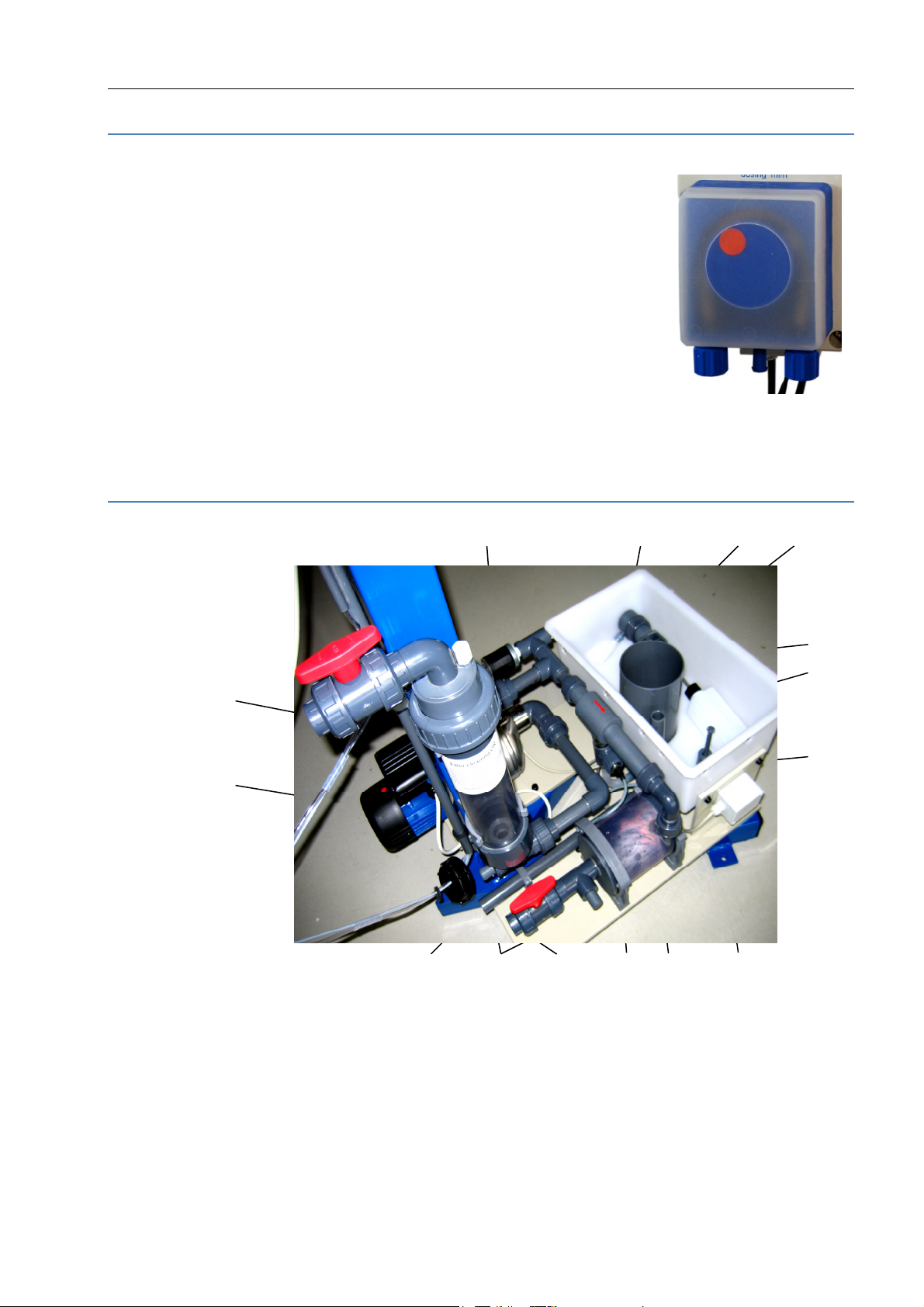
2.5 Dissolving System
20 21 22 23
32
26
34 33
31
24
27
29
20 pressure switch 28 allocation rinsing water
21 floating valve 29 level control switch
22 flushing tank 30 union bush with washer nozzle
23 flushing tube 31 outlet ball valve d25
24 flow monitoring 32 supply connection d25 with filter
25 venturi nozzle 33 fitting to connect pressure gauge
26 circulation pump 34 overflow tube
27 cyclone mixing/dissolving chamber
The dissolving water is normally supplied from before or from behind the filter. There must be a
sufficient supply pressure to avoid dry running and/or cavitation on the booster pump, at
28
25
30
WDT Operating Instruction GRANUDOS 25/45/100 (S41C-06/12) page 9 of 27
least 0.2 bar. The pump pressure is controlled by the pressure switch (20) fitted on top of the pump. At
a pressure below the set switch pressure by sucking air or at pressure drops the machine stopps, lamp 1
& 2 will burn. At works 1,5 bar is set.
The supply water is divided in the allocation rinsing water (28) at the discharge of the booster pump
(26), one way leading to the flushing tank (22), the other branch directed to the venturi nozzle (25),
where the water is sucked together with the dosed chemicals out of the flushing tank. The supply water
flow is controlled by means of a floating valve (21) and a flow switch (24), the latter being installed in
the suction tube of the venturi. To mix the chemicals and to ensure the complete dissolving of the
chlorine granules a cyclone mixing chamber (27) is fitted after the venturi.. To ensure that chlorine and
acid do not come into contact with each other in the open tank part of the dissolving assembly a
sophisticated control system is installed:
- metering of the two chemicals is regulated with pauses between the metering intervals
(para 2.6.3, page 11 “
- power supply for chlorine and acid dosing motors are connected by a relay system so that
only one or none of them can get power (24VDC) and dose chemical.
- flow switch (24) , level switch (29), pressure switch (20) supervising water supply and flow
conditions. If any non-compliance with the given limits occurs, the GRANUDOS will be
switched off.
Dosing Performance - Dosing scheme
”).
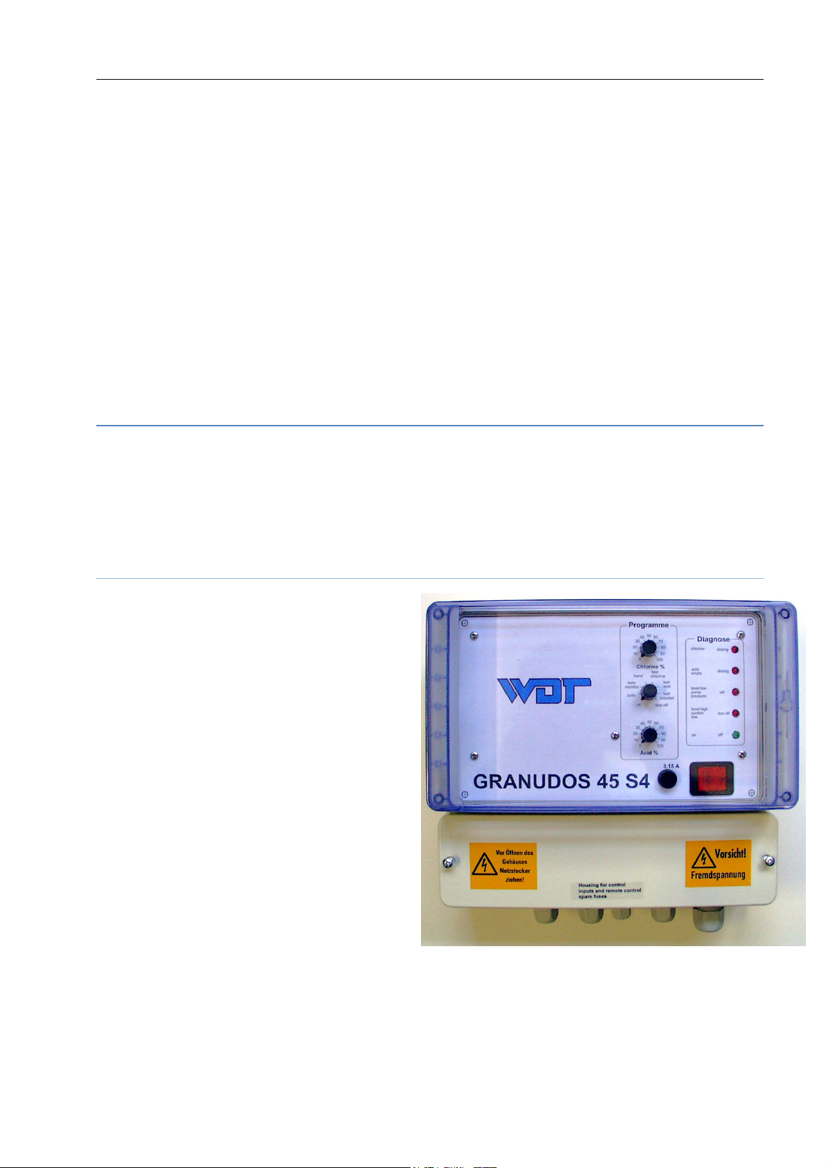
2.6 Control System with program GR S41
The microprocessor based control of the GRANUDOS has three functions:
- Contains the circuit self check and dosing and test programmes
- Function control and interruption display (1 green + 4 red LED). If any
interruption is displayed, the GRANUDOS dosing is switched off.
- All faults activate the fault remote control.
2.6.1 Operation elements
operation elements on front plate
- mains switch
- main fuse 3,15 Aslow
- 1 programme switch for test- and
Operation programmes
- 2 knobs to adjust the wanted dosing
performance for chlorine and acid
- 1 LED green to monitor operation
- 4 LED red to monitor irritations
operation elements inside on control plate:
2 fuses 500 mAslow,
Code-switch to select programme alteratives
The control system is enclosed within a dust
proof and splash proof housing (IP 65). External switches and fault remote indication are to be connected
at the back of the control panel.
 Loading...