

Granudos 45-S3, 45/100 Operating Instructions Manual

WDT Operating Instructions GRANUDOS 45/100 (S3 - 04/02) Page 1 of 1
_______________________________________________________________________________
Series No..........................Customer..........................................Date of delivery……….……………
Operating instructions GRANUDOS 45/100-S3
Safety Devices
1. Chlorine and acid may not be mixed together
or with other chemicals
Pay attention to the safety devices on
chemical containers
2. The dosing hopper must be screwed even
and firmly to the container
3. Ensure after changing a drum, that it is firmly
fixed in position and the securing systems are
used
4. In service the dissolving system must be
covered with the supplied cover
5. Only instructed personnel may work with the
GRANUDOS
6. Ensure booster pump does not run dry,
always isolate pump when backwashing.

WDT Operating Instructions GRANUDOS 45/100 (S3 - 04/02) Page 2 of 2
_______________________________________________________________________________
TABLE OF CONTENTS
Safety devices
Test certificate
page
1 Function of GRANUDOS 45-S3 2
1.1 Data, Measures, Performance 3
1.2 Drum carrier 3
1.3 Dosing Assembly Chlorine 4
1.4 Acid dosing 4
1.5 Dissolving System 5
1.6 Control Panel (GRD S3) 6
1.6.1 Front plate 6
1.6.2 Dosing control system 7
1.6.3 Dosing performance adjustment 7
1.6.4 Dosing by auto controller 7
2 Installation 8
2.1 Electrical Connection 8
2.2 Providing acid 8
2.3 Tubing 9
3 Start 10
3.1 Deaeration of the water supply tubing 10
3.2 Water level in flushing tank 10
3.3 Water flow/Suction performance of injector 10
3.4 Loading the chemical drum onto machine 10
3.5 Acid dosing 11
4 Irritations Diagnosis 12
4.1 Irritations indicated by red lamps/control switches 12
4.2 Irritations notmonitored/indicated by switches 13
5 Maintenance 13
6 Wiring Diagram/Fuses 14
7 Spare parts list 15
8. Maintenance list 17
WDT Operating Instructions GRANUDOS 45/100 (S3 - 04/02) Page 3 of 3
_______________________________________________________________________________
1. Function of GRANUDOS
1.1. Data, Measures, Performance
The GRANUDOS 45-S3 dosing system comprises:
- main vertical support with rotating drum carrier
assembly
- calcium hypochlorite granules metering
- acid metering equipment
- dissolving system
- control panel
Measures:
base needed: 120x70x180 cm
height: 140 cm
weight: 50 kg
material:
main vertical support and drum carrier:
steel, zinc and powder coated
other parts: PVC, PE
booster pump
centrifugal pump: 0,3 kW, 230 VAC,
supply pressure: minimum 0,2 bar
Water flow: app. 1000 l/h
Dosing Performance:
chlorine: GR 45: 1,5 kg/h. GR 100: 3 kg/h
acid: GR 45: 3 l/h, GR 100: 3 l/h
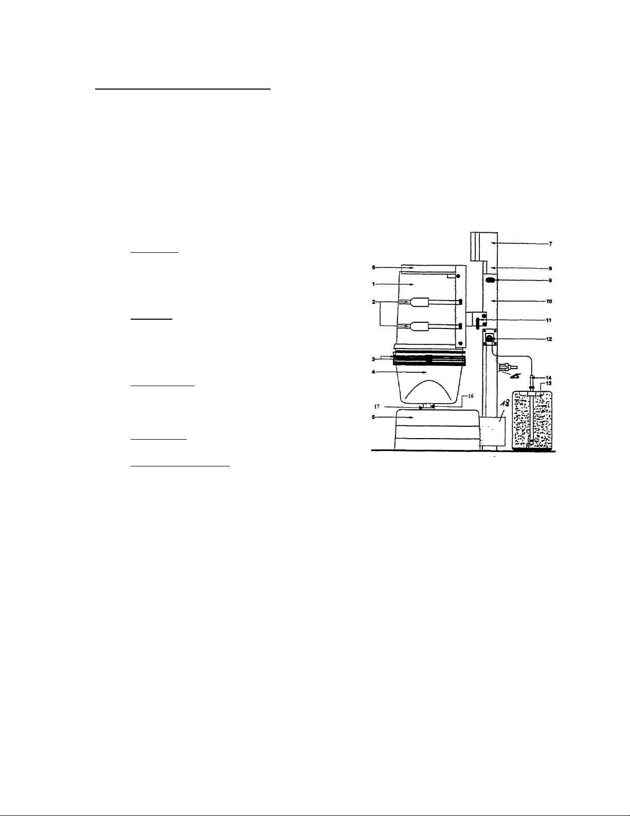
1 drum 9 type label.
2 2 clamp bands 10 vertical carrier
3 lid curl 11 locker
4 dosing hoper 12 acid pump
5 dissolving system 13 acid carboy
6 drum carrier 14 carboy lance
7 controlsystem 15 water supply with filter
8 conn. Housing 16 heated dosing nozzle
17 dust protection
18 pump cover
WDT Operating Instructions GRANUDOS 45/100 (S3 - 04/02) Page 4 of 4
_______________________________________________________________________________
1.2 The Drum Carrier
The rotating drum carrier assembly (6) is fixed to the main vertical support (10). The drum
(1) with hypochlorite is fixed on the carrier assembly (6) by 2 band clamps (2) and a
retaining belt. The dosing hopper (3) is fixed on the drum in place of the drum lid. The
carrier with the drum is then turned through 180° to the dosing position, the chemical is
dosed into the dissolving system (5) where it is fully dissolved and conveyed by a venturi to
the swimming pool.
1.3 Chlorine Dosing Assembly
19
10 dosing hopper 16 hopper cover
11 dosing motor 17 knocker (option)
12 dosing screw 18 seal washer
13 motor mounting 19 dosing hopper screw ring
14 dosing nozzle heated
15 drum empty switch with adjusting screw and LED
The dosing screw (12) meters the chlorine through the heated dosing nozzle (14) to the
dissolving system. If the drum empty switch (15) is indicating, the LED 4 burns
continuously, dosing is running on,. The knocker (17, optional) gives a hit to the hopper at
each dosing motor run so supporting dosing.
Dosing performance is adjusted by 2 turning knobs at front fascia, see para starting.
1.4 Acid Dosing
The acid is dosed down in the flushing cone (23 - see next para) by the peristaltic pump
which is fitted directly right side at the vertical support. If acid level switch indicates acid
container empty, the GRANUDOS chlorine dosing is stopped too to avoid scaling.
As acid use sulphuric acid 37%. Concentrated hydrochloric acid (HCI) penetrates the pump
hose and will attack the pump rollers and further the pump
WDT Operating Instructions GRANUDOS 45/100 (S3 - 04/02) Page 5 of 5
_______________________________________________________________________________
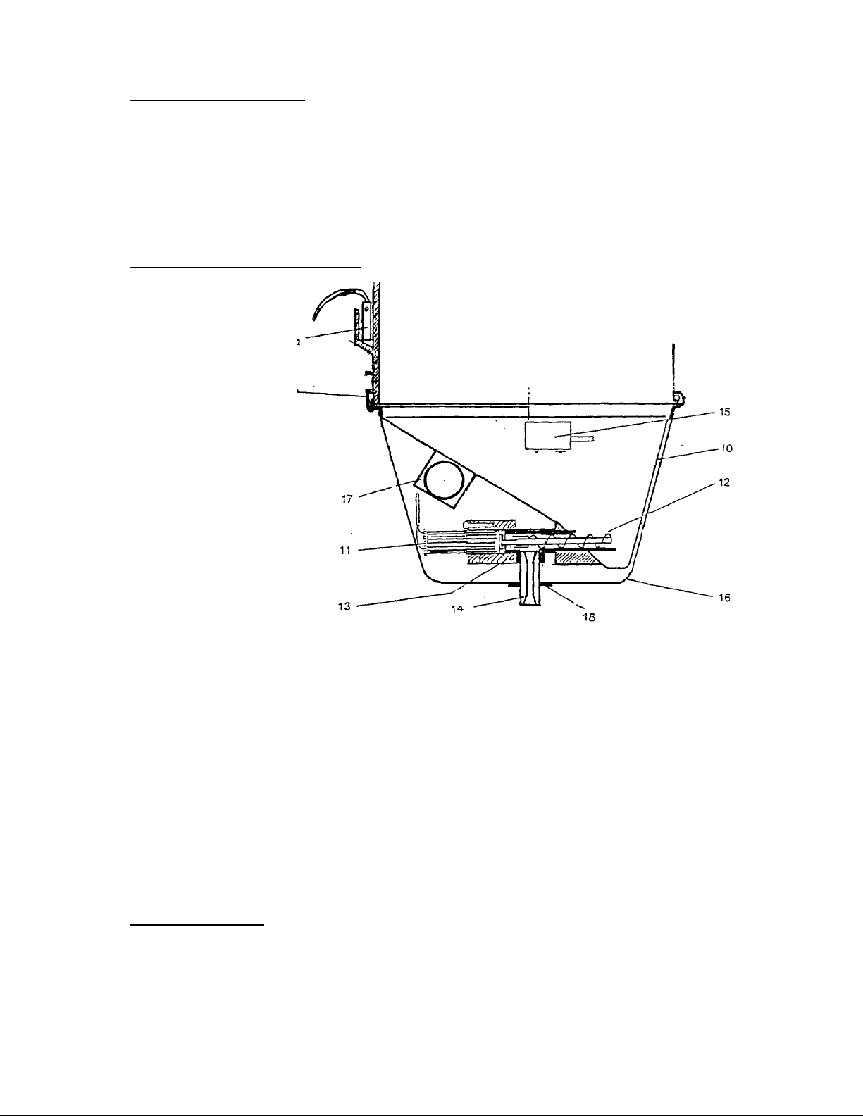
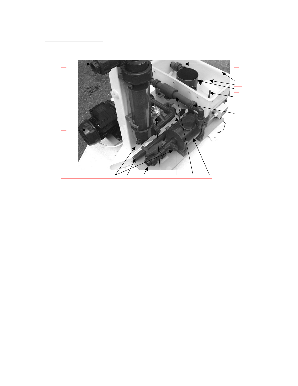
1.5 Dissolving System
32
21
22
21a
23
29
30
26
33 34 31 20 24 25 27
2
0
20 pressure switch (optional) 27 cyclone mixing/dissolving
chamber
21 floating valve 29 level switch
22 flushing tank 30 union bush with nozzle inside
23 flushing tube 31 outlet ball valve
24 suction tube with flow control 32 water supply ball valve
25 venturi nozzle 33 fitting ¼” for test pressure gauge
26 booster pump
The supply water coming from the pool water is divided at the discharge of the booster
pump (26), one way leading to the flushing tank (22), the other branch directed to the
venturi nozzle (25), where the water is drawn out of the flushing tank together with the
dosed chemicals. The supply water flow is controlled by means of a floating valve (21) and
monitored by a flow switch (24), the latter being installed in the suction tube of the venturi.
To mix the chemicals and to ensure the complete dissolving of the hypochlorite granules a
cyclone mixing chamber (27) is fitted after the venturi. Optionally the supply water
pressure is monitored by the pressure switch (20).
WDT Operating Instructions GRANUDOS 45/100 (S3 - 04/02) Page 6 of 6
_______________________________________________________________________________
To ensure that calcium hypochlorite and acid do not come in contact with each other in the
open tank part of the dissolving assembly a sophisticated control system is installed:
- metering of the two chemicals is regulated with pauses between the metering
intervals (para 4.2 'Adjusting dosing performance').
- power supply for chlorine and acid dosing motors are connected by a relay system so
that only one of them can get power (24VDC).
- flow switch (24) , level switch (29), and optional pressure switch monitoring water
supply and flow conditions. If any non-compliance with the given limits occurs, the
dosing will be switched off.
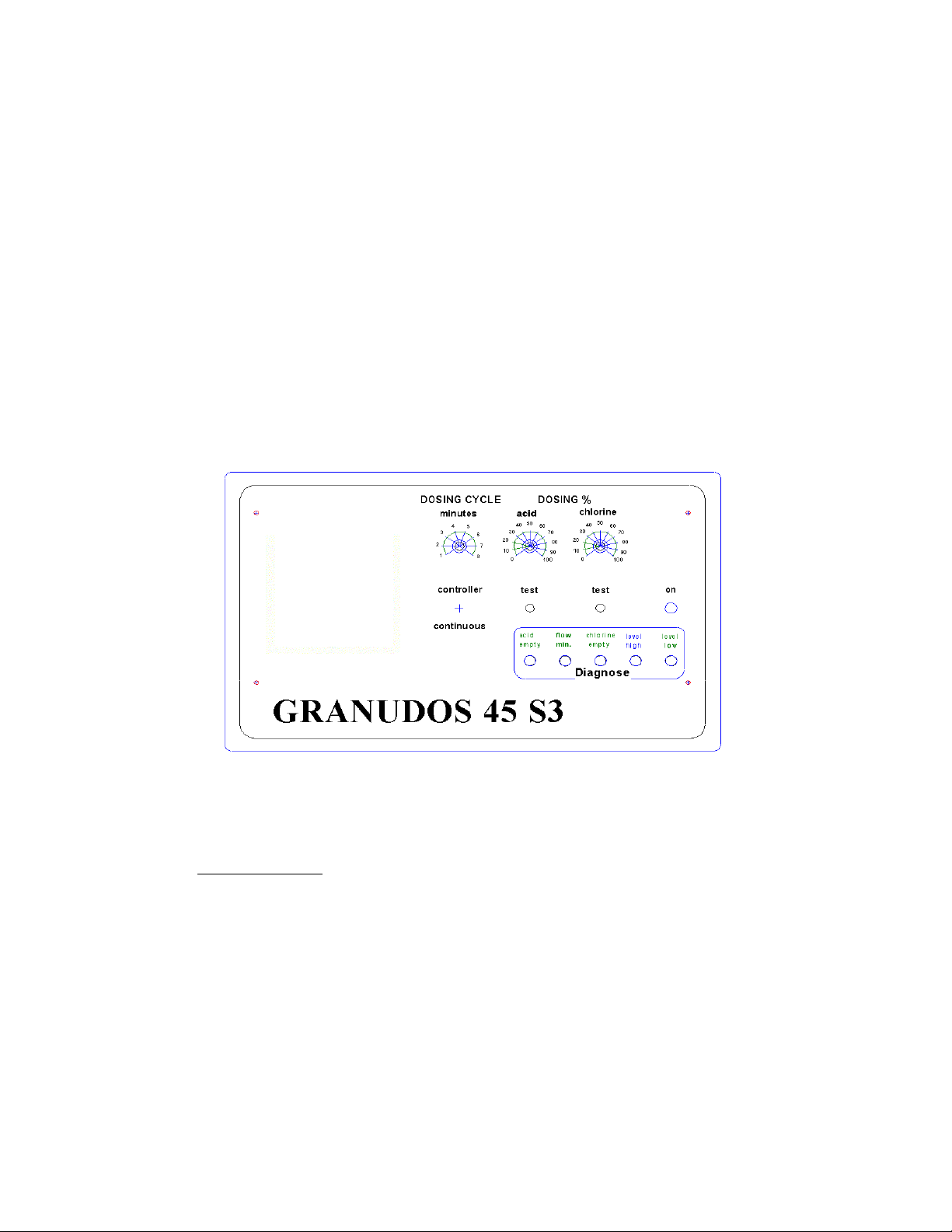
1.6 Control Panel (GRD S3)
1.6.1 Front plate – service elements
The control board is of analogical type, one part together with the front plate. All
connectors are push type directly on the control board.
Service elements:
On connector housing below:
1 main switch on/off
1 main fuse 3,15 amp slow
On front plate:
1 select switch for dosing by auto controller or for continuous dosing
1 potentiometer knob to adjust dosing cycle from 1 – 8 minutes
2 potentiometer knobs to adjust dosing time of dosing motors chlorine and acid:
100 % = 20 seconds
2 push button switches to test dosing motors of the chemicals: if pushed, dosing is
running accordingly if no fault is indicated.
1 green lamp to indicate service
 Loading...