

Grant's Automation e-Gate SLD-24V-D Instruction Manual
INSTALLATION MANUAL
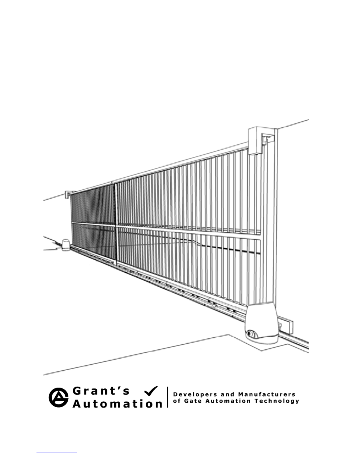
e-Gate SLD-24V-D
24V Bi-Parting Sliding Gate Operator for Gates to 500kg
FOR

CONTENTS
PRE-INSTALLATION CHECK LIST . . . . . . 1
MAXIMUM SIZE OF GATE FOR THE SLD-24V-D . . . . . . . . . . . . . . . . 1
GATE OPERATOR FREQUENCY OF USE . . . . . . . . . . . . . . . . . . 2
IMPORTANT SAFETY INSTRUCTIONS! . . . . . . . . . . . . . . . . . . . 3
TOOLS AND HARDWARE REQUIRED . . . . . . . . . . . . . . . . . . . . 4
PREPARING THE GATE . . . . . . . . . . . . . . . . . . . . . . . . . 5
GUIDE POST CLEARANCE . . . . . . . . . . . . . . . . . . . . . . . . 5
AUTOMATIC OPERATOR FITTING REQUIREMENTS . . . . . . . . . . . . . . 6
ACCESSORIES THAT CAN BE ADDED . . . . . . . . . . . . . . . . . . . 7
SAFETY PHOTOCELL 7
DIGITAL KEYPAD AND/OR INTERCOM 8
A GROUND LOOP VEHICLE DETECTOR 8
CABLING REQUIREMENTS . . . . . . . . . . . . . . . . . . . . . . . . . 9
BASIC CABLING GUIDE 9
FULL CABLING GUIDE 9
TYPE AND SIZE OF CABLE 10
HOW IT WORKS . . . . . . . . . . . . . . . . . . . . . . . . . . . . . 11

9 STEPS TO INSTALLING THE SLD-24V-D . . 12
STEP 1 - INSTALL CABLING . . . . . . . . . . . . . . . . . . . . . . . 12
TIPS FOR RUNNING LOW VOLTAGE CABLE YOURSELF. 13
STEP 2 - FIT THE OPERATOR . . . . . . . . . . . . . . . . . . . . . . 13
POSITION OF THE OPERATOR 13
CHECK HEIGHT OF THE OPERATOR 14
RAISE THE HEIGHT OF THE OPERATOR IF NEEDED 14
FIX THE OPERATOR IN PLACE 15
MANUALLY RELEASE THE OPERATOR 15
STEP 3 - FIT THE RACK TO THE GATE . . . . . . . . . . . . . . . . . . . .16
STEP 4 - TERMINATE CABLING . . . . . . . . . . . . . . . . . . . . . . 20
SLD-24V-S GENERAL WIRING DIAGRAM 20
CHECKING THE GATE DIRECTION 21
TERMINATING THE BATTERY AND CHARGER (BATTERY VERSIONS ONLY) 22
TERMINATING A PHOTOCELL 23
TERMINATING A LIGHT 23
TERMINATING DIGITAL KEYPAD, KEY SWITCH OR PRESS BUTTON 24
TERMINATING GROUND LOOP VEHICLE DETECTOR 24
TERMINATING A 7-DAY TIMER, DIGITAL KEYPAD OR KEYSWITCH 25
TERMINATING AN INTERCOM 25
STEP 5 - SET THE CLOSE LIMIT WITH THE MAGNET . . . . . . . . . . . . 26
STEP 6 - TUNE THE REMOTE CONTROLS IN . . . . . . . . . . . . . . . . 28
REMOTE CONTROL OPEN, STOP AND MANUAL CLOSE 25
REMOTE CONTROL OPEN WITH AUTO-CLOSE 25
REMOVING REMOTE CONTROLS 26
REMOTE CONTROLLED PEDESTRIAN ENTRY 26
USER ADDING REMOTE CONTROL AT A LATER DATE 26
STEP 7 - LEARN GATE OPEN LIMIT . . . . . . . . . . . . . . . . . . . . 30
STEP 8 - ACTIVATE AND TEST ACCESSORIES . . . . . . . . . . . . . . . 31
OTHER OPTIONS FOR CONTROL INPUTS 31
STEP 9 - FINE TUNE GATE OPERATOR PREFERENCES . . . . . . . . . . . . 32
CHANGING THE AUTO-CLOSE DELAY 32
CHANGING THE PHOTOCELL-CLOSE DELAY 32
CHANGING THE PEDESTRIAN-CLOSE DELAY 33
CHANGING UP THE LOCK/LIGHT OUTPUT 33
CHANGING THE LEVEL OF SOFT START AND SOFT STOP 34
CHANGING THE GATE OBSTRUCTION SENSITIVITY 34
RETURN TO FACTORY SETTINGS . . . . . . . . . . . . . . . . . . . . . 35
WHAT HAPPENS IF THERE IS A POWER CUT? . . . . . . . . . . . . . . . . 35
ACCESSORIES . . . . . . . . . . . . . . . . . . . . . . . . . . . . 36
TROUBLE SHOOTING . . . . . . . . . . . . . . . . . . . . . . . . . . 36
WARRANTY . . . . . . . . . . . . . . . . . . . . . . . . . . . . . . 37
1
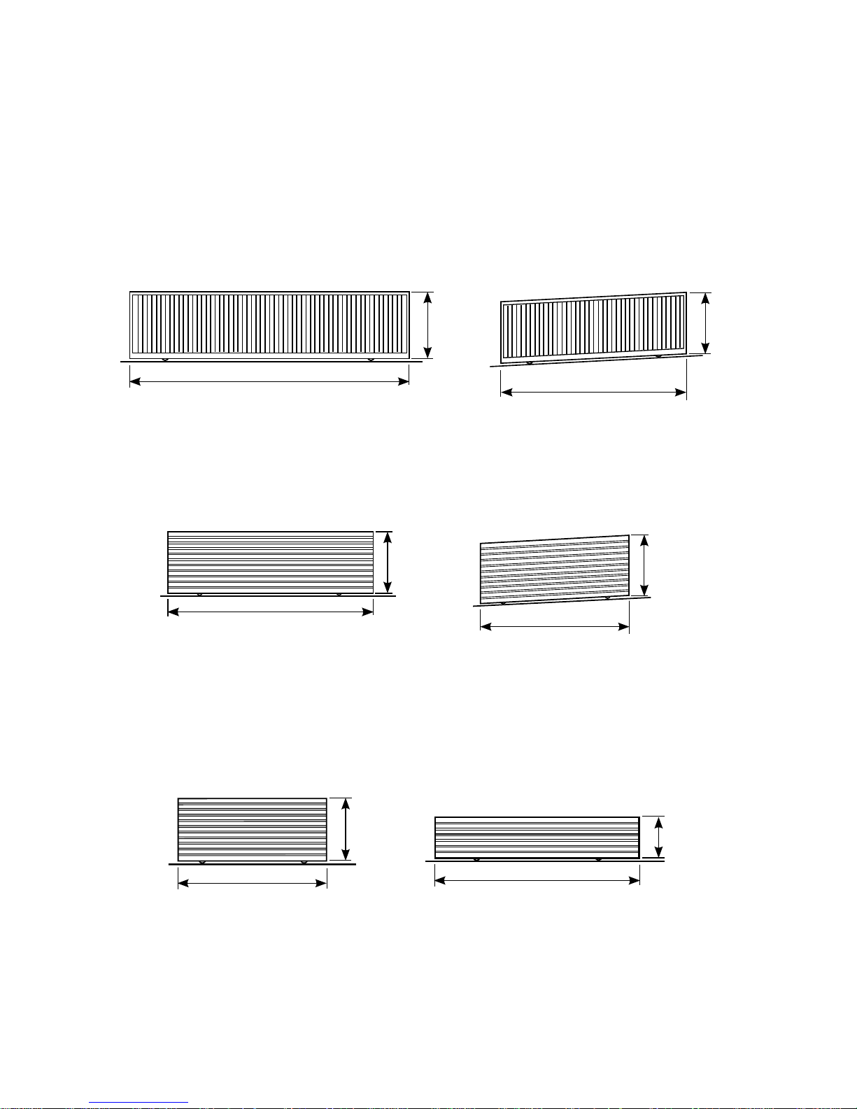
MAXIMUM SIZE OF GATE PER SINGLE LEAF FOR THE SLD-24V-D
Aluminium Gates with Open Bar Cladding
Aluminium Gates with Aluminium or Timber Slats or Steel Gates with Open Bars
If this Gate Operator is installed on a gate that is too Heavy it may not work properly.
Steel Gates with Hardwood Slats or Solid Hardwood gates
8m Wide
2m High
6m Wide
1.8m High
200mm rise
6m Wide
1.8m High
4m Wide
1.8m High
100mm rise
4m Wide
1.8m High
6m Wide
1.2m High
PRE-INSTALLATION CHECK LIST
2
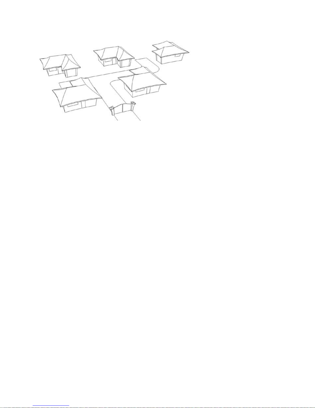
GATE OPERATOR FREQUENCY OF USE
This Gate Operator is rated
for RESIDENTIAL AND
LIGHT COMMERCIAL
USE ONLY, which is
a maximum of Five
Households or Ten
Carpark spaces for a
commercial building. Any
more than this and the life
span of the operator can
be reduced.
The warrantee does not cover wear and tear due to average use of more
than 60 operations per day.
If higher frequency of use is required consider using an industrial sliding gate
operator rated for continuous use. Gates that have a lot of users are more likely
to be struck by a vehicle so need to be a robust industrial grade operator.
Battery Powered System Maximum Frequency of use
A Battery operated system with a Charge transformer can handle:
Up to 60 operations per day.•
If charge power goes off the operator will run on battery for a day or two •
depending on frequency of use.
If the battery runs flat it • should be allowed to recharge overnight before the
operator is used.
Solar Powered Systems
The size of the Solar Panel and Battery depends very strongly on the weather
conditions in the area, the size of the gate and amount of use the gate gets.
The amount of sun also varies with the time of the year so the worse case
senerio must be considered.
In areas that get a lot of sun all year round, have a light weight gate and have
no more than 20 operations per day a 10 Watt Solar panel and 14Ah Battery will
do. For up to 60 Operations per day, heavy gate or area’s that don’t get a lot of
sun allow for a 20 Watt or 40 Watt solar panel and 26Ah Battery.
Normally Solar systems are only economic for larger rural properties that don’t
have power near the gate.

3
IMPORTANT SAFETY INSTRUCTIONS!
CONSIDERING THE GENERAL PUBLIC:
When Installing an Automatic Gate that will be entered from a public road
way,makesuretheGateisplacedfarenoughfromtheroadtopreventtrafc
congestion.
The Gate must be installed in a location that provides adequate clearance
between it and adjacent structures when opening and closing to reduce risk of
entrapment.
Install the Gate Operator on the inside of the property and fence line. DO NOT
install an opener on the outside of the gate where the public has access to it.
The Gate and Gate Operator must comply with any applicable local council
regulations.
CONSIDERING THE USERS:
If using the Auto-close feature it is highly recommended that a Point to Point
Photo Electric Safety Beam (Photocell) is installed to prevent the gate closing
on any vehicle using the gate.
It is also recommended that a seperate small side gate is used for pedestrians
particularly if there will be children, disabled or elderly people using the gate.
If push buttons, key switches or Digital Keypads are installed, they should be
within sight of the gate but not placed so the user will be tempted to reach
through the gate to activate the gate operator.
USER AWARENESS:
It is important to make sure everyone that will be using the gate is aware of the
following dangers associated with automatic Gates: do not contact any part of
the gate or walk in the path of the gate while it is moving. Never let children
play with the gate controls. Do not attempt to “beat the gate” while it is closing.
This is extremely dangerous.
In the event you sell the property, make sure the new owners have a copy of
these instructions. If you lose the instructions they can be downloaded from:
www.grantsautomation.com.au.

4
TOOLS AND HARDWARE REQUIRED
YOU MAY ALSO NEED THESE ITEMS BEFORE INSTALLATION
For Battery Powered Systems and systems with accessories added Low
Voltage Cable is required between the Transformer and the Gate operator
see “Cabling Requirements” for more information.
You may also need conduit, which is available from Electrical trade
suppliers and hardware stores.
For Mains Powered Systems you will need a mains power point mounted on a
free standing post in front of the gate next to automatic operator. Check with
local regulations before installing a mains voltage power point yourself, you may
need a registered electrician to do this for you.
THE TOOLS YOU’LL NEED INCLUDE:
A basic set of hand tools will be needed including: side cutters, pliers, wire
strippers, a range of phillips head screw drivers, a small flat head screw driver
for terminal block screws and a socket set.
You’ll also need a tape measure, marking pen, an elecric drill with hammer
action and variable speed control, a 10mm hammer drill bit and socket bit for
10mm or 3/8” tek screws. An angle grinder is also handy although a hacksaw
will do if you don’t have one.
If you intend on doing you own low voltage cabling a pair of conduit cutters
are handy although a hacksaw can also be used. If you wish to run cabling
across the driveway you will need either a 230mm angle grinder with masonary
grinding disc or a hand held concrete cutter. You can hire these if necessary.
If you’ll be running cabling across a lawn or garden you’ll need a spade and
mattock for digging a low trench. If it’s a long run then a small trench digger can
be hired to do the job.
5
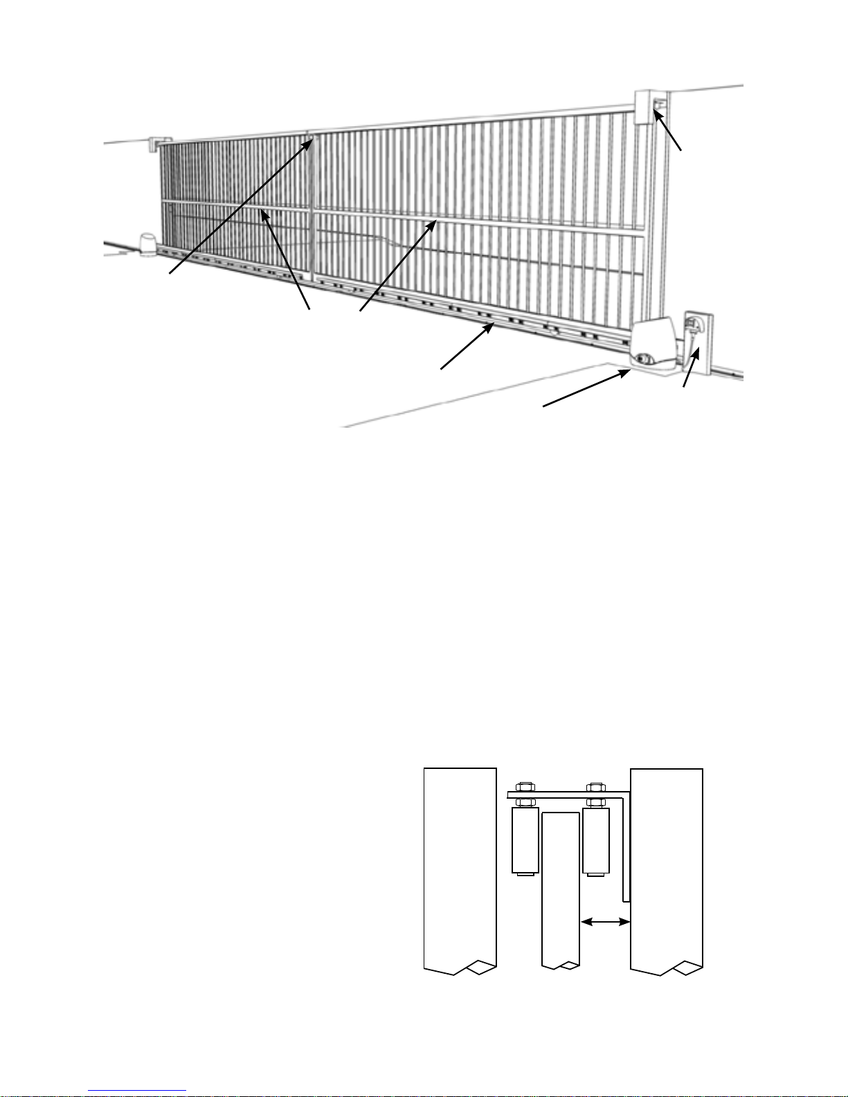
Make sure that both gates have been properly installed, are straight and slide
freely throughout their entire length without any grabbing from the guides
or track any where along each gate. The GATE TRACK MUST BE IN A
STRAIGHT LINE any sudden dips or rises may prevent a gate operator from
working properly. Repair or replace all worn or damaged gate hardware prior to
installation. Gate posts less than 150mm wide should be made from steel not
timber. Replace posts where necessary. A freely moving gate will require less
force to operate and will enhance the performance of the operator and give a
long working life.
The operators should be well drained and not be submersed in water or have
water running past it in heavy rain.
Keeper between
gates to be
aligned correctly
Guides
must
move
easily
for entire
length of
gate.
Gate Operators to be
on a level concrete pad
Gate Track must be Straight,
gate should NOT run or catch
on the track.
Power Point (if used)
on free standing post
in front of the gate
Gates must be Straight
not twisted or bowed.
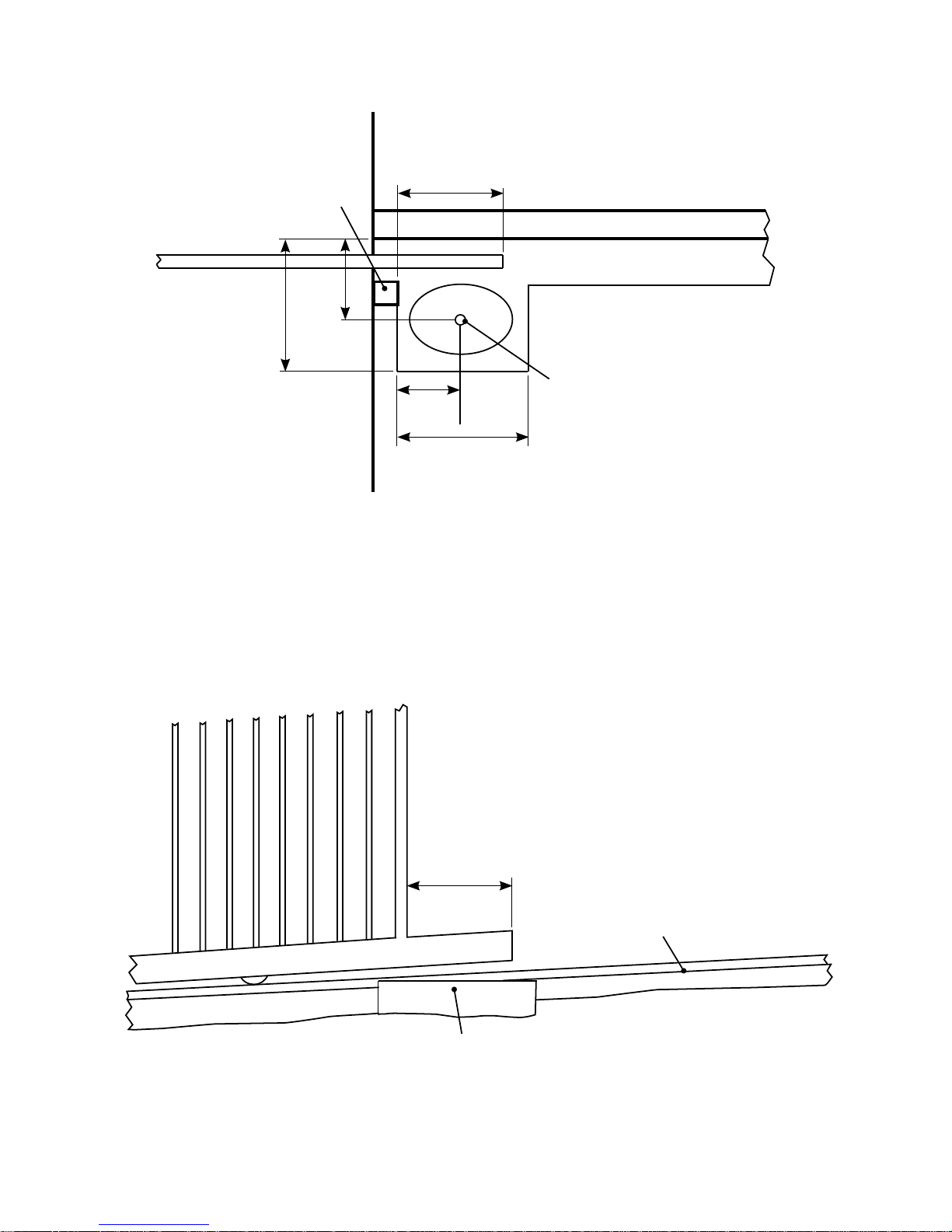
GUIDE POST CLEARANCE
Gate
Front
Fence or
Wall
Rear
Guide Post
if used
60mm
If using a guide post behind a gate
allow at least 60mm clearance for
the Rack. If the guide is fitted to the
front Fence or Wall the clearence
has no effect so long as the Gate
does not contact it at all.
Open Hard Stops
required to set
each gates open
limit
PREPARING THE GATE
6
The Gate Operator requires a level concrete pad to mount on. Even if the driveway is sloping the
concrete pad for the Operator MUST BE LEVEL!. The concrete pad should no less than 100mm
thick and after concrete is poured it must be given a week or so to harden before the operator is
installed.
If the Gate Operator power is to be hard wired it’s a good idea to place a piece of conduit into the
concrete pad, during installation, for the power cabling later on.
AUTOMATIC OPERATOR FITTING REQUIREMENTS
DRIVEWAY
Gate
Operator
FRONT FENCE/WALL
CONCRETE FOOTING AND PAD
Concrete
Pad
400mm
Concrete Pad
400mm
GATE
Guide
Post if used
Conduit for Power Cable to
come out of concrete pad here
if Power is Hardwired.
250mm
200mm
Extra Gate Length
for Automatic
Operator
300mm
PLAN VIEW
LAWN OR GARDEN
DRIVEWAY
Extra Gate
Length for
Automatic
Operator
need only be the
bottom rail
Concrete Pad must be level
even if gate track isn’t
GATE
Gate track and footing must
be straight but can be on a
gentle slope
FRONT VIEW
DRIVEWAY
LAWN OR GARDEN
Concrete Pad must be well
drained and not ever be sitting
in water even after heavy rain
7
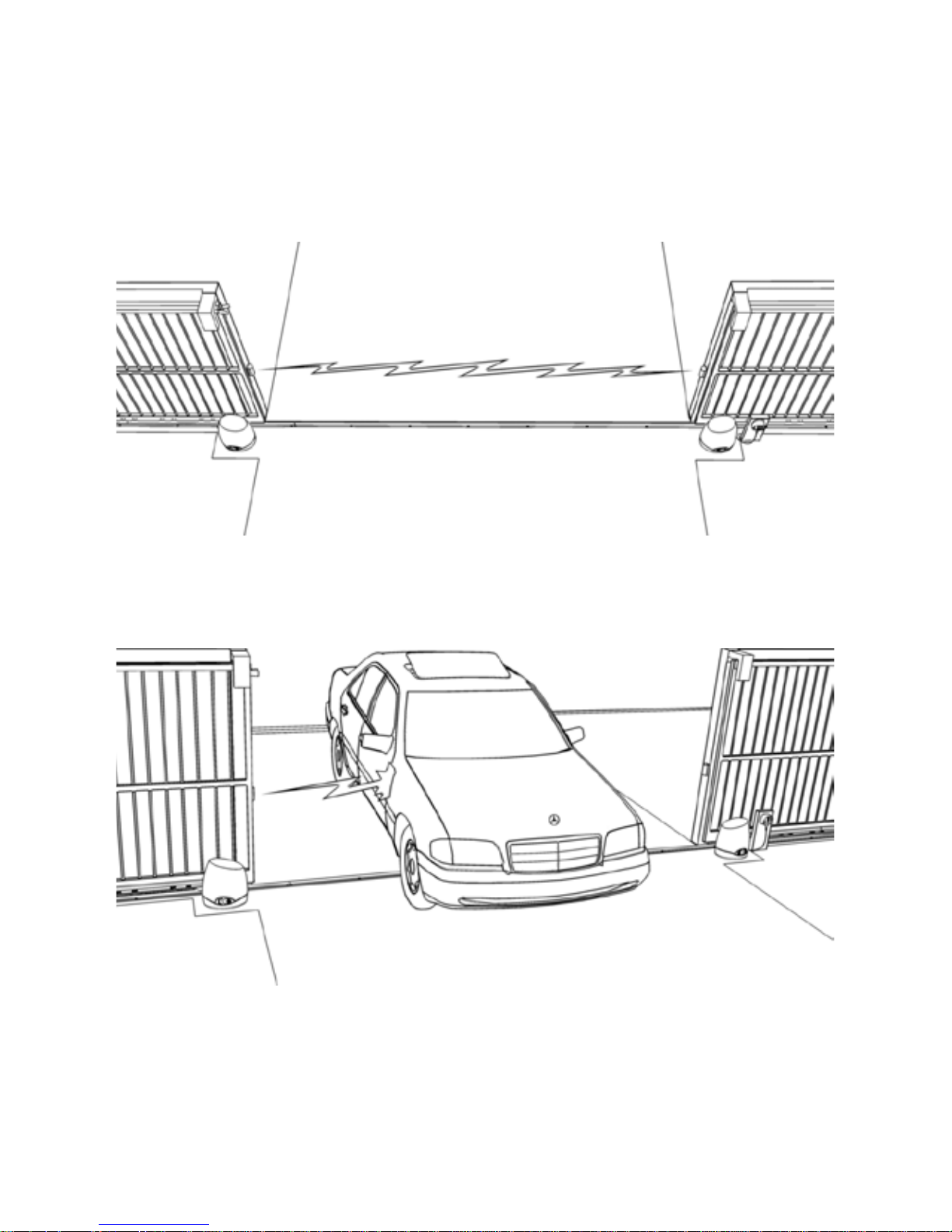
SAFETY PHOTOCELL
Photocells are a safety device that prevent the gate from closing on a vehicle.
They are highly recommended if using the Auto-close feature, as the gate
may close at any time.
A Photocell consists of an Invisible Low Power Infrared point to point Beam
Transmitted from one side of a gate to the other. REFLECTOR BEAMS are
NOT recommended for outdoors.
A Photocell prevents a Gate from Closing on a car
If the Photocell’s beam is interrupted by a vehicle, the gate won’t close. The
Photocell can also be used to control the closing of the gate.
ACCESSORIES THAT CAN BE ADDED
8
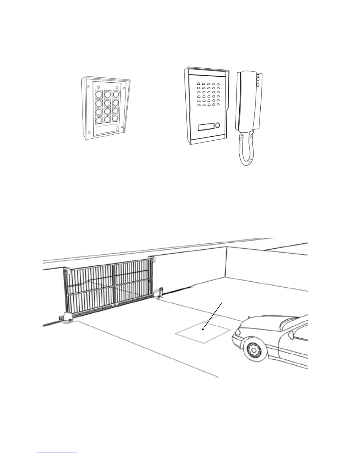
DIGITAL KEYPAD AND/OR INTERCOM
To allow access to visitors or tradesman any brand of digital keypad and/or
intercom can be installed (provided the intercom has a door release feature).
An Intercom allows visitors to call the
house and speak with the occupier. If
the occupier wishes to let the visitor in
they can do so by pressing a button on
the intercom to open the gate.
A GROUND LOOP VEHICLE DETECTOR
Loop of wire in
driveway used to
detect vehicles
A Digital Keypad allows access to
anyone with the correct pin number.
A ground loop in the driveway detects any vehicles approaching the gate and
opens it automatically to let them out. Pedestrians cannot use the ground loop
to open the gate, which is a safe guard from anyone jumping the fence.
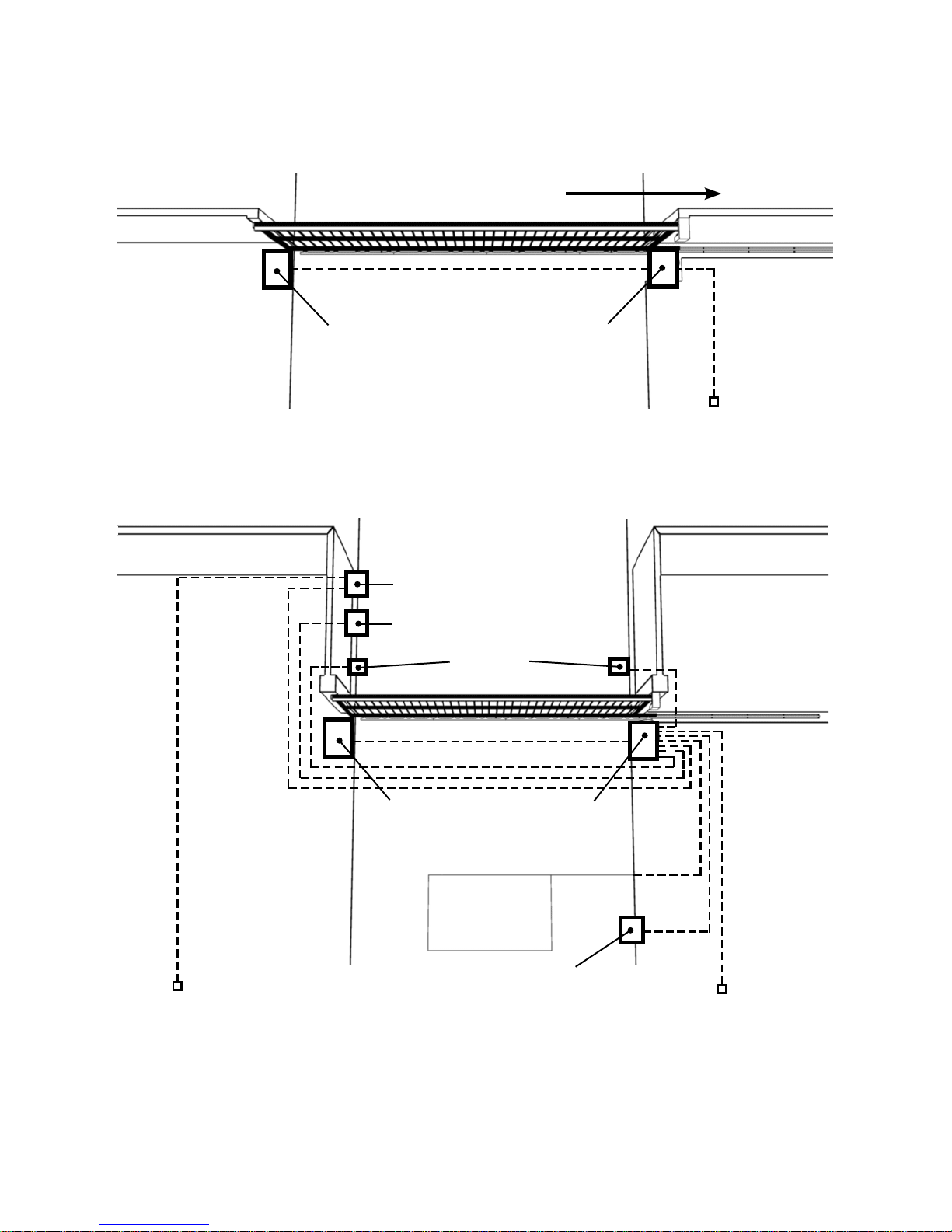
9
CABLING REQUIREMENTS
Photocell
Digital Keypad
Intercom
To Intercom Inside
station
To Power
Source
To Power
Source
BASIC CABLING GUIDE
FULL CABLING GUIDE RIGHT HAND GATE
Master Gate
Operator
If power source is hard wired 240VAC Mains this should be kept at least 100mm
away from any low voltage cabling.
Digital Keypad,Keyswitch
or Press Button(alternate to ground Loop)
Ground Loop
Open Direction
Slave Gate
Operator
Master Gate
Operator
Slave Gate
Operator
Power Required on
ONE SIDE ONLY
Power
Required on
ONE SIDE
ONLY
 Loading...