

Page 1

Preface
SY M8 6 45 5 V G G A
Copyright
This publication, including all photographs, illustrations and software, is protected
under international copyright laws, with all rights reserved. Neither this manual, nor
any of the material contained herein, may be reproduced without written consent of
the author.
Version 1.0
Disclaimer
The information in this document is subject to change without notice. The manufacturer makes no representations or warranties with respect to the contents hereof and
specifically disclaims any implied warranties of merchantability or fitness for any
particular purpose. The manufacturer reserves the right to revise this publication and
to make changes from time to time in the content hereof without obligation of the
manufacturer to notify any person of such revision or changes.
Trademark Recognition
Microsoft, MS-DOS and Windows are registered trademarks of Microsoft Corp.
MMX, Pentium, Pentium-II, Pentium-III, Celeron are registered trademarks of Intel
Corporation.
Other product names used in this manual are the properties of their respective
owners and are acknowledged.
Federal Communications Commission (FCC)
This equipment has been tested and found to comply with the limits for a Class B
digital device, pursuant to Part 15 of the FCC Rules. These limits are designed to
provide reasonable protection against harmful interference in a residential installation. This equipment generates, uses, and can radiate radio frequency energy and, if
not installed and used in accordance with the instructions, may cause harmful interference to radio communications. However, there is no guarantee that interference
will not occur in a particular installation. If this equipment does cause harmful
interference to radio or television reception, which can be determined by turning the
equipment off and on, the user is encouraged to try to correct the interference by one
or more of the following measures:
• Reorient or relocate the receiving antenna
• Increase the separation between the equipment and the receiver
• Connect the equipment onto an outlet on a circuit different from that to
which the receiver is connected
• Consult the dealer or an experienced radio/TV technician for help
Shielded interconnect cables and a shielded AC power cable must be employed with
this equipment to ensure compliance with the pertinent RF emission limits governing
this device. Changes or modifications not expressly approved by the system’s manufacturer could void the user’s authority to operate the equipment.
Page 2

ii
Preface
Declaration of Conformity
This device complies with part 15 of the FCC rules. Operation is subject to the
following conditions:
• This device may not cause harmful interference.
• This device must accept any interference received, including interference that may cause undesired operation.
Canadian Department of Communications
This class B digital apparatus meets all requirements of the Canadian Interferencecausing Equipment Regulations.
Cet appareil numérique de la classe B respecte toutes les exigences du Réglement sur
le matériel brouilieur du Canada.
About the Manual
The manual consists of the following:
Describes features of the
motherboard.
Go to
H
page 1
Describes installation of
motherboard components.
Go to
H
page 9
Go to
H
page 29
Chapter 2
Installing the Motherboard
Chapter 1
Introducing the Motherboard
Chapter 3
Using BIOS
Chatper 4
Trouble Shooting
Provides basic trouble shoot
ing tips
page 63
Go to
H
Provides information on using
the BIOS Setup Utility.
Page 3

iii
Chapter 2
9 9
9 9
9
Installing the Motherboard 9
Safety Precautions............................................................................9
Choosing a Computer Case.............................................................9
Installing the Motherboard in a Case............................................9
Checking Jumper Settings.............................................................10
Setting Jumpers......................................................................10
Checking Jumper Settings......................................................11
Jumper Settings......................................................................11
Installing Hardware...................................................................13
Installing the Processor.........................................................13
Installing Memory Modules...................................................16
Expansion Slots......................................................................17
Connecting Optional Devices.................................................19
Installing a SATA Hard Drive................................................22
Connecting I/O Devices............................................................... 23
Connecting Case Components.....................................................24
Front Panel Header................................................................27
TT
TT
T
ABLE OF CONTENTSABLE OF CONTENTS
ABLE OF CONTENTSABLE OF CONTENTS
ABLE OF CONTENTS
Preface i
Chapter 1 1
Introducing the Motherboard 1
Introduction...................................................................................1
Feature............................................................................................2
Specifications................................................................................4
Motherboard Components..........................................................6
Page 4

1
Introducing the Motherboard
Chapter 1
Introducing the Motherboard
Introduction
Thank you for choosing the SYM86455 motherboard. This motherboard is a high performance, enhanced function motherboard designed to support the LGA1151 socket
for Intel latest Skylake processors for high-end business or personal desktop markets.
This motherboard is based on Intel® H110 Chipset for best desktop platform solution. It supports up to 16 GB of system memory with dual channel DDR4 2133 MHz.
Two PCI Express16X Gen3 slots (1 with PCIex4) and one PCIE1X Gen2 are supported,
intended for Graphics Interface. In addition, four PCI slots are for extending usage.
It integrates USB 2.0 and USB 3.0 interface, supporting up to six USB 2.0 ports (two
USB 2.0 ports at the rear panel and three USB 2.0 headers support additional four
USB 2.0 ports) and four USB 3.0 ports at rear panel).
The motherboard is equipped with advanced full set of I/O ports in the rear panel,
including PS/2 mouse and PS/2 keyboard connectors, one HDMI port, one COM port,
one VGA port, one DVI port, two USB 2.0 ports, four USB 3.0 ports, two LAN ports, and
audio jacks for line-in, line-out.
In addition, this motherboard supports four SATA 6.0Gb/s connectors for expansion.
Page 5

2
Introducing the Motherboard
Feature
• DirectX11.1-compliant GCN-based graphics architecture
• Supports “Hyper-Threading” technology APU
• Supports Win8 and UEFI Secure Boot.
“Hyper-Threading” technology enables the operating system into thinking
it’s hooked up to two processors, allowing two threads to be run in parallel, both
on separate “logical” processors within the same physical processor.
The motherboard uses Skylake series CPU that carries the following features:
Processor
Chipset
• Supports DDR4 2133 (1GB/ 2GB/ 4GB/ 8GB) SDRAM with two-channel
architecture
• Up to 16GB 288 pin DIMM memory module support
Memory
Audio
• 2 Channel High Definition Audio Codec
• Meets Microsoft Windows Logo Program and Lync audio
requirements
• All DACs supports 44.1k/48k/96k/192kHz sample rate
• Software selectable 2.5V/3.2V/4.0V VREFOUT
• Direct Sound 3DTM compatible
• Power Support: Digital: 3.3V; Analog: 5.0V
The integrated Skylake H110 chip is a dual-chip with proven reliability and high
performance.
• Support one PCI Express x1 slot
• Integrated four SATA 6.0 Gb/s Host Controllers
• Six USB 2.0 ports supported
• Four USB 3.0 port supported
• Support two PCI Express x16 Gen3 slots (1 with PCIex4)
• Support four PCI slots
• Intel
®
High Definition Audio Controller
Page 6

3
Introducing the Motherboard
Expansion Options
The motherboard comes with the following expansion options:
• One PCI Express x1 slot
• Four SATA 6.0Gb/s connectors
• Support two PCI Express x16 Gen3 slots (1 with PCIex4)
• Support four PCI slots
The motherboard has a full set of I/O ports and connectors:
Integrated I/O
• Two LAN ports
• One Serial port (COM)
• One DVI port (DVI-D)
• two USB 2.0 ports
• One VGA port
• One HDMI port
• Four USB 3.0 ports
• One PS/2 keyboard and PS/2 mouse connector
• Audio jacks for line-out and Mic-in
The firmware can also be used to set parameters for different processor clock
speeds.
• Power management
• Wake-up alarms
• APU parameters
• APU and memory timing
• Graphic parameters
BIOS Firmware
This motherboard uses AMI BIOS that enables users to configure many system
features including the following:
1. Some hardware specifications and software items are subject to change
without prior notice.
2. Due to chipset limitation, we recommend that motherboard be operated
in the ambiance between 0 and 60 °C. (NOTICE: Test method: bare PCB
with 100% loading running Pass Mark 7.0 at chamber 60 °C)
Ethernet LAN
The onboard LAN provides the following features:
• Supports PCI ExpressTM 1.1
• IEEE 802.3/z
• Wake-on-LAN (including from S3, S4, S5, power button off)
and remote wake-up support
• PXE and RPL support
Page 7
4
Introducing the Motherboard
Specifications
CPU
• Intel® H110 ChipsetChipset
• Dual-channel DDR4 memory architecture
• 2 x DDR4 DIMM sockets support up to 16 GB
• Supports DDR4 2133 MHz
Memory
• 2 x PCI Express x16 Gen3 slots (1 with PCIex4)
• 1 x PCI Express x1 Gen2 slot
• 4 x PCI slots
• Supported by Intel® H110 Express Chipset
- 4 x Serial ATA 6.0 Gb/s devices
Expansion
Slots
Storage
• 1 x PS/2 keyboard & PS/2 mouse connectors
• 1 x HDMI port
• 1 x COM port
• 1 x VGA port
• 1 x DVI port (DVI-D)
• 2 x USB 2.0 ports
• 4 x USB 3.0 ports
• 2 x RJ45 LAN connectors
• 1 x COM port (RS232/422/485 Controlled by BIOS)
• 1 x Audio port (Line in, line out)
Rear Panel I/O
LAN • Intel I211AT
• Intel I219V
• Realtek ALC662 HD audio CODEC
Audio
• LGA1151 socket for
Intel Skylake processors, Dual cores
• 1 x 24-pin ATX Power Supply connector
• 1 x 4-pin ATX_12V Power Supply connector
• 1 x 4-pin CPU_FAN connector
• 1 x 4-pin SYS_FAN connector
• 4 x SATA III 6.0Gb/s connectors
• 1 x Front panel switch/LED header
• 1 x Front panel audio header
• 1 x USB 2.0 header support additional two USB 2.0 ports
• 1 x 5-pin USB 2.0 header support additional one USB 2.0 port
• 1 x USB 2.0 port
• 5 x Onboard Serial port headers (COM2~6) (RS232)
• 1 x Clear CMOS header with jumper
• 1 x ME disable header with jumper
• 1 x Buzzer header
• 1 x INT_SPK header
• 1 x DIO header
• 1 x J1 jumper
• 1 x J2 jumper
• 1 x J3 jumper
Internal I/O
Connectors &
Headers
Page 8

5
Introducing the Motherboard
• AMI BIOS with 64Mb SPI Flash ROM
• Supports Plug and Play, STR (S3) / STD (S4) , Hardware monitor
• Supports ACPI & DMI
• Audio, LAN, can be disabled in BIOS
•F7
hot key for boot up devices option
System BIOS
Form Factor • Micro ATX Size, 305mm x 244mm
Page 9
6
Introducing the Motherboard
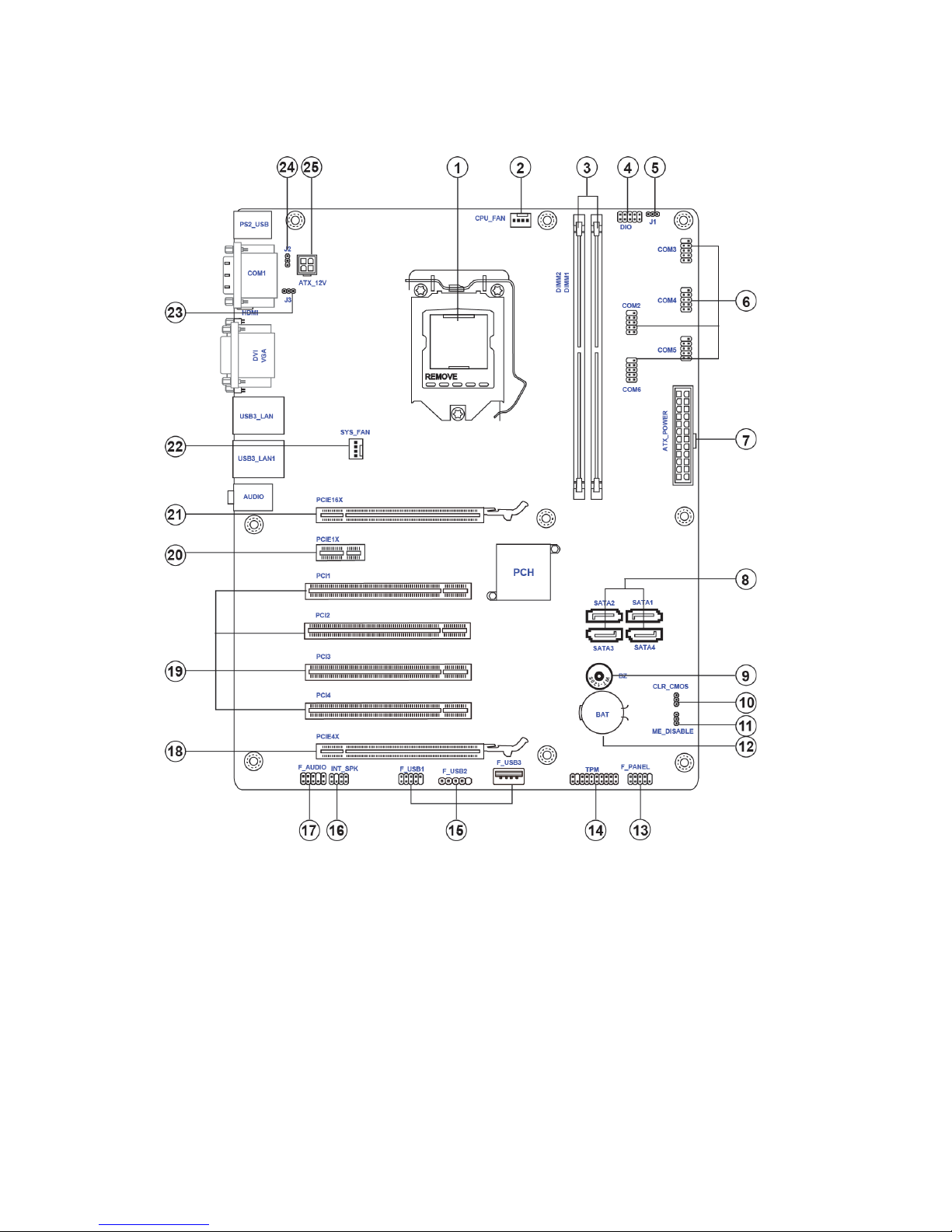
Motherboard Components
Page 10

7
Introducing the Motherboard
Table of Motherboard Components
LABEL COMPONENTS
1. CPU
LGA1151 socket for Intel Skylake processors
2. CPU_FAN CPU cooling fan connector
3. DIMM1~2 288-pin DDR4 Module slots
4. DIO Digital Input & output header
5. J1 Power mode Select jumper
6. COM2~6 Onboard serial port headers
7. ATX_POWER Standard 24-pin ATX power connector
8. SATA1~4 Serial ATA 6.0Gb/s connectors
9. BZ
Buzzer
10. CLR_CMOS Clear CMOS header with jumper
11. ME_DISABLE Disble ME header wi th jumper
12. BAT Battery
13. F_PANEL Front panel switch/LED header
14. TPM Trusted Platform Modual header
15. F_USB1~3 Front panel USB 2.0 headers
16. INT_SPK Speaker header
17. F_AUDIO Front panel audio header
18. PCIE4X PCI Express x16 Gen2 slot for graphics interface
19. PCI1~4 32-bit add-on card slots
20. PCIE1X PCI Express x1 slot
21. PCIE16X PCI Express x16 Gen3 slot for graphics interface
22. SYS_FAN System cooling fan connector
25. ATX_12V Auxiliary 4-pin power connector
23. J3
COM1 Transmission Distance Select jumper
(J3 and J2 need to switch at the same time)
24. J2
COM1 Transmission Distance Select jumper
(J3 and J2 need to switch at the same time)
This concludes Chapter 1. The next chapter explains how to install the motherboard.
Page 11

8
Introducing the Motherboard
Memo
Page 12

9
Installing the Motherboard
Chapter 2
Installing the Motherboard
Safety Precautions
• Follow these safety precautions when installing the motherboard
• Wear a grounding strap attached to a grounded device to avoid damage from static electricity
• Discharge static electricity by touching the metal case of a safely
grounded object before working on the motherboard
• Leave components in the static-proof bags they came in
• Hold all circuit boards by the edges. Do not bend circuit boards
Choosing a Computer Case
There are many types of computer cases on the market. The motherboard complies
with the specifications for the DTX system case. Some features on the motherboard
are implemented by cabling connectors on the motherboard to indicators and switches
on the system case. Make sure that your case supports all the features required.
Most cases have a choice of I/O templates in the rear panel. Make sure that the I/O
template in the case matches the I/O ports installed on the rear edge of the
motherboard.
This motherboard carries a ATX form factor of 305 x 244 mm. Choose a case that
accommodates this form factor.
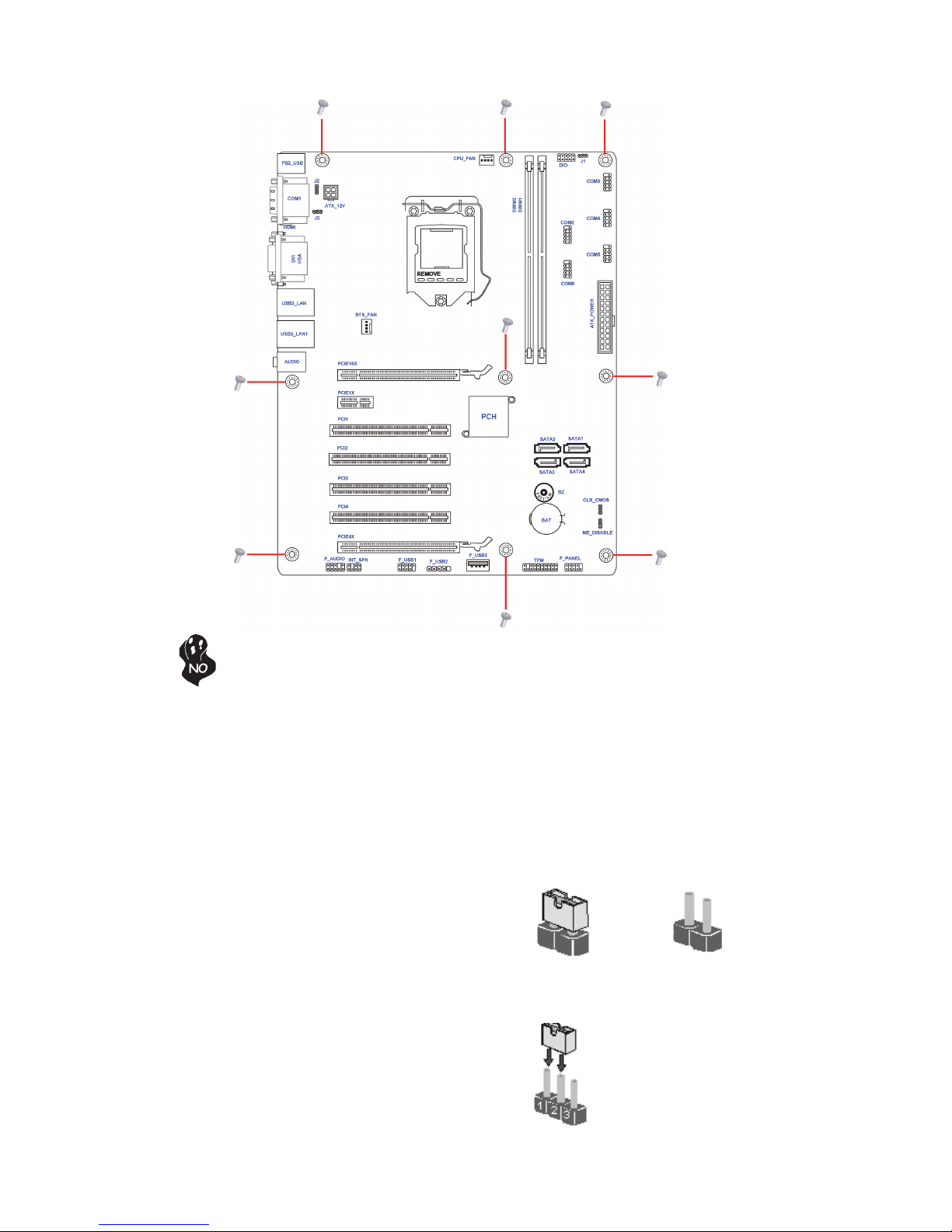
Installing the Motherboard in a Case
Refer to the following illustration and instructions for installing the motherboard in
a case.
Most system cases have mounting brackets installed in the case, which correspond
the holes in the motherboard. Place the motherboard over the mounting brackets
and secure the motherboard onto the mounting brackets with screws.
Ensure that your case has an I/O template that supports the I/O ports and expansion
slots on your motherboard.
Page 13
10
Installing the Motherboard
Checking Jumper Settings
This section explains how to set jumpers for correct configuration of the motherboard.
Setting Jumpers
Use the motherboard jumpers to set system configuration options. Jumpers with
more than one pin are numbered. When setting the jumpers, ensure that the jumper
caps are placed on the correct pins.
The illustrations show a 2-pin jumper. When
the jumper cap is placed on both pins, the
jumper is SHORT. If you remove the jumper
cap, or place the jumper cap on just one pin,
the jumper is OPEN.
This illustration shows a 3-pin jumper. Pins
1 and 2 are SHORT.
SHORT OPEN
Do not over-tighten the screws as this can stress the motherboard.
Page 14
11
Installing the Motherboard
Checking Jumper Settings
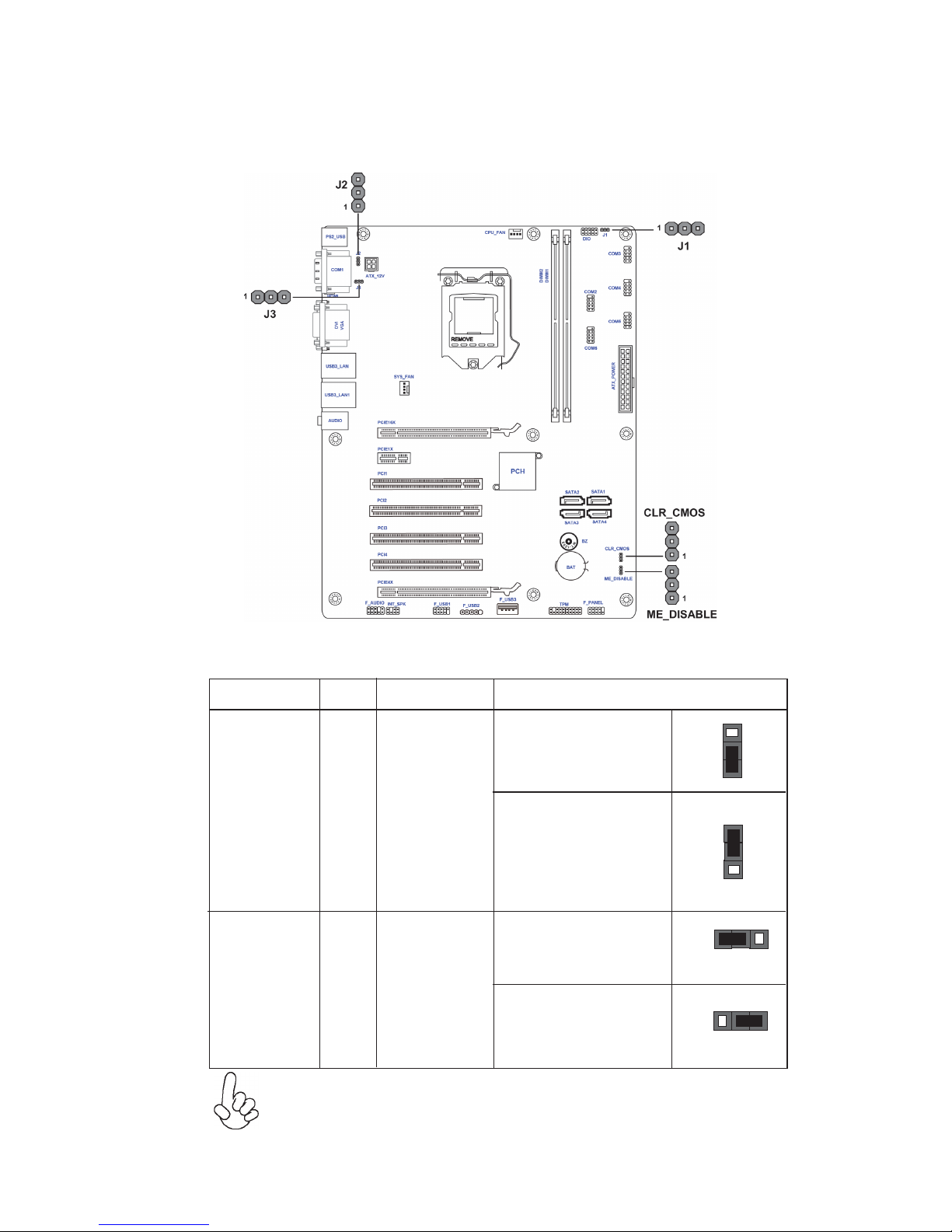
The following illustration shows the location of the motherboard jumpers. Pin 1 is
labeled.
Jumper Settings
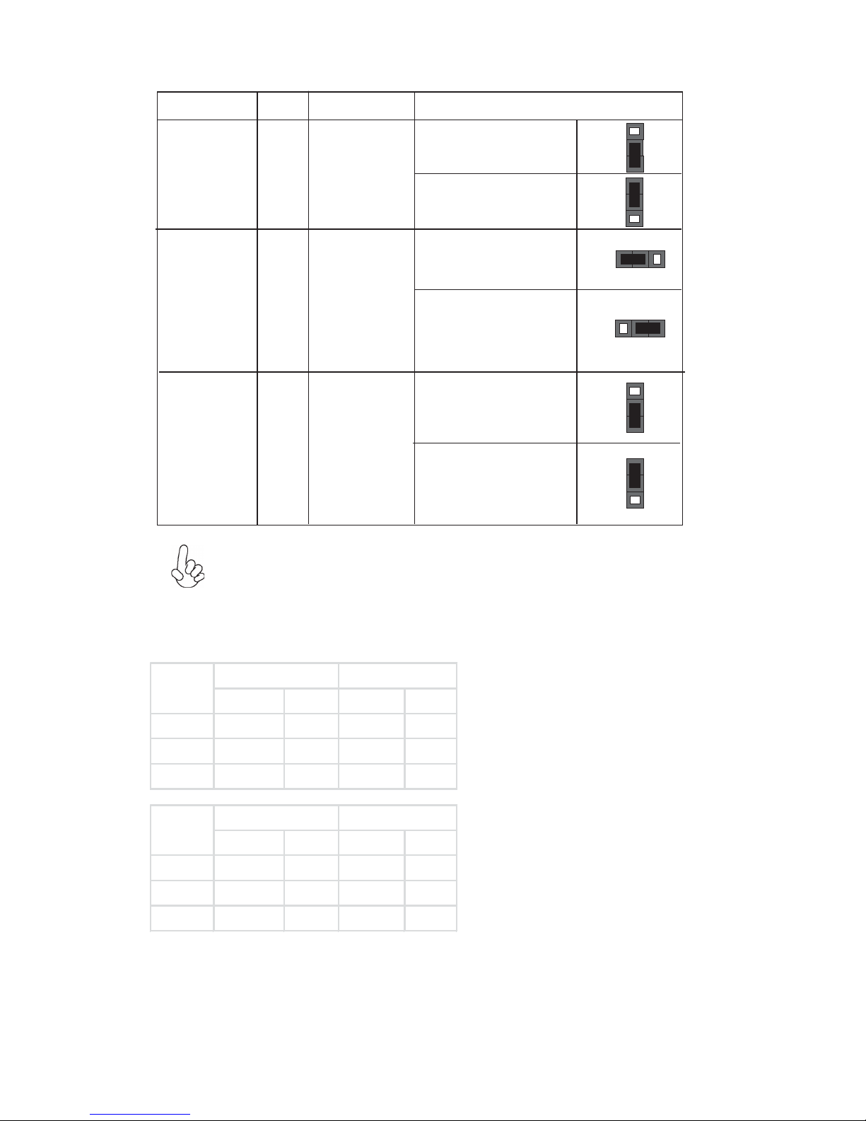
Jumper
Type
Description Setting (default)
CLR_CMOS
3-pin
Clear CMOS
1-2: NORMAL
Before clearing the
CMOS, make sure to
turn off the system.
1
To avoid the system instability after clearing CMOS, we recommend
users to enter the main BIOS setting page to “Load Default Settings”
and then “Save and Exit Setup”.
(Default)
1
2-3: CLEAR
J1
3-pin
1-2: ATX
1
(Default)
1
2-3: AT
Power supply
switch
Page 15
12
Installing the Motherboard
Jumper
Type
Description Setting (default)
ME_DISABLE
3-pin
Disable ME
1-2: NORMAL
1
(Default)
1
2-3: ME DISABLE
J3* 3-pin
1-2: Long distance
transmission (for
RS-422, RS-485)
1
(Default)
1
2-3: Short distance
transmission
COM1
Transmission
Distance
switch
J2*
3-pin
1-2: Long distance
transmission (for
RS-422, RS-485)
1
(Default)
1
2-3: Short distance
transmission
COM1
Transmission
Distance
switch
*J3 and J2 need to switch at the same time.
S0‐>S5‐>G3 S0‐>G3 S0‐>S5‐>G3 S0‐>G3
PowerOn S 5‐>S0 S5‐>S0 S5‐>S5 S5‐>S5
Las tState S5‐>S5 S5‐>S0 S5‐>S5 S5‐>S5
PowerOff S 5‐>S5 S5‐>S5 S5‐>S5 S5‐>S5
ATXMode
EUP=Disabled EUP=Enabled
S0‐>S5‐>G3 S0‐>G3 S0‐>S5‐>G3 S0‐>G3
PowerOn S 5‐>S0 S5‐>S0 S5‐>S0 S5‐>S0
Las tState S5‐>S0 S5‐>S0 S5‐>S0 S5‐>S0
PowerOff S 5‐>S0 S5‐>S0 S5‐>S0 S5‐>S0
ATMode
EUP=Disabled EUP=Enabled
Note:
Page 16

13
Installing the Motherboard
Installing Hardware
Caution: When installing a CPU heatsink and cooling fan make sure that
you DO NOT scratch the motherboard or any of the surface-mount
resistors with the clip of the cooling fan. If the clip of the cooling fan
scrapes across the motherboard, you may cause serious damage to the
motherboard or its components.
On most motherboards, there are small surface-mount resistors near the
processor socket, which may be damaged if the cooling fan is carelessly
installed.
Avoid using cooling fans with sharp edges on the fan casing and the clips.
Also, install the cooling fan in a well-lit work area so that you can clearly
see the motherboard and processor socket.
Before installing the Processor
This motherboard automatically determines the CPU clock frequency and system
bus frequency for the processor. You may be able to change the settings in the system
Setup Utility. We strongly recommend that you do not over-clock processors or
other components to run faster than their rated speed.
This motherboard has an LGA1151 socket. When choosing a processor, consider the
performance requirements of the system. Performance is based on the processor
design, the clock speed and system bus frequency of the processor, and the quantity
of internal cache memory and external cache memory.
Warning:
1. Over-clocking components can adversely affect the reliability of the
system and introduce errors into your system. Over-clocking can
permanently damage the motherboard by generating excess heat in
components that are run beyond the rated limits.
2. Always remove the AC power by unplugging the power cord from the
power outlet before installing or removing the motherboard or other
hardware components.
Fail-Safe Procedures for Over-clocking
When end-users encounter failure after attempting over-clocking, please take the
following steps to recover from it.
1. Shut down the computer.
2. Press and hold the “Page Up Key (PgUp)” of the keyboard, and then boot the
PC up.
3. Two seconds after the PC boots up, release the “Page Up Key (PgUp)”.
4. The BIOS returns to the default setting by itself.
Installing the Processor
Page 17
14
Installing the Motherboard
CPU Installation Procedure
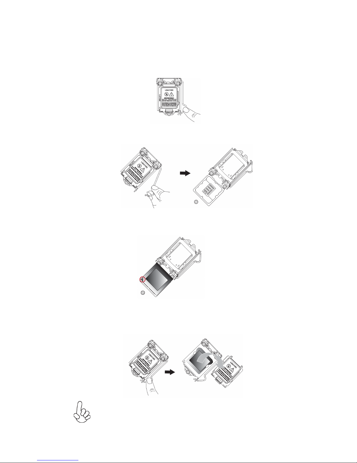
The following illustration shows CPU installation components.
A. Press the hook of lever down with your thumb and pull it to the
right side to release it from retention tab.
B. Lift the tail of the load lever and rotate the load plate to fully open
position.
C. Grasp the edge of the package substrate. Make sure pin 1 indicator
is on your bottom-left side. Aim at the socket and place the package
carefully into the socket by purely vertical motion.
D. Rotate the load plate onto the package IHS (Intergraded Heat
Spreader). Engage the load lever while pressing down lightly onto the
load plate. Secure the load lever with the hook under retention tab.
Then the cover will flick automatically.
Please save and replace the cover onto the CPU socket if processor is
removed.
Page 18
15
Installing the Motherboard
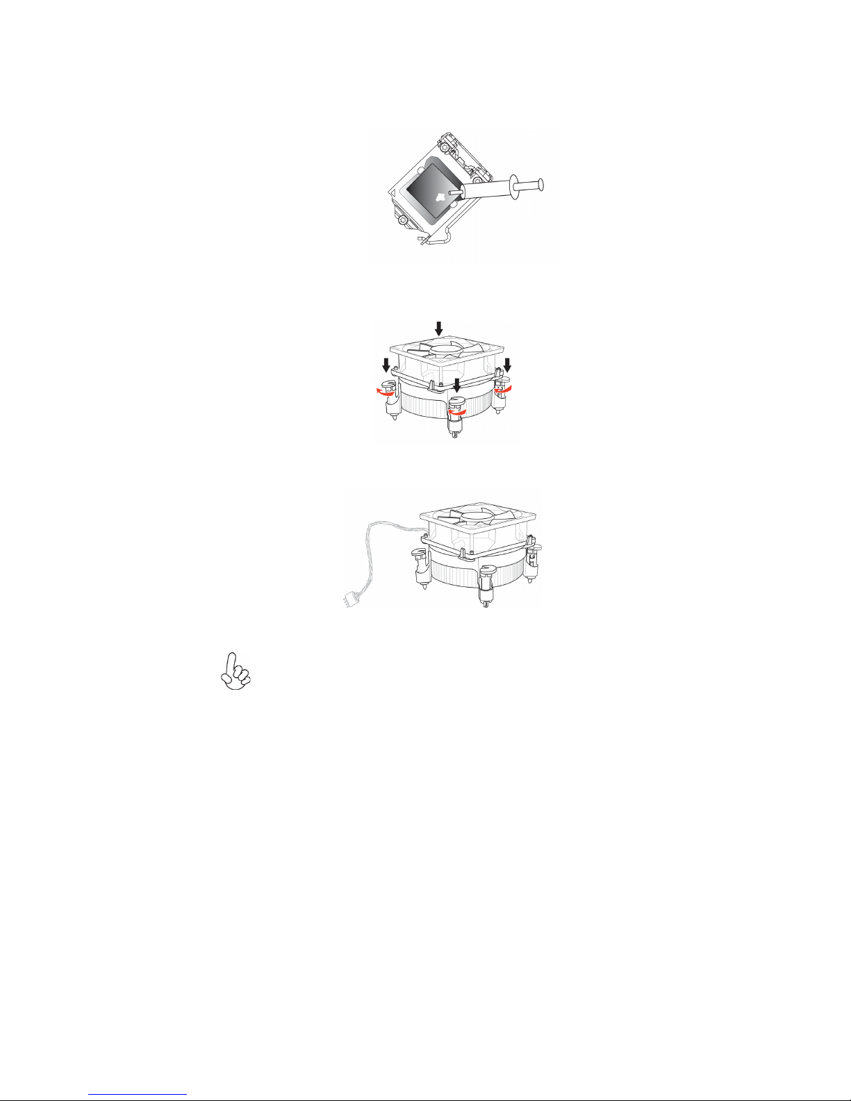
E. Aplly some thermal grease onto the contacted area between the heatsink
and the CPU, and make it to be a thin layer.
F. Fasten the cooling fan supporting base onto the CPU socket on the
motherboard. And make sure the CPU fan is plugged to the CPU fan
connector.
G. Connect the CPU cooler power connector to the CPU_FAN connector.
1. To achieve better airflow rates and heat dissipation, we suggest
that you use a high quality fan with 3800 rpm at least. CPU fan and
heatsink installation procedures may vary with the type of CPU fan/
heatsink supplied. The form and size of fan/heatsink may also vary.
2. DO NOT remove the CPU cap from the socket before installing a
CPU.
3. Return Material Authorization (RMA) requests will be accepted
only if the motherboard comes with the cap on the LGA1151 socket.
Page 19
16
Installing the Motherboard
Installation Procedure
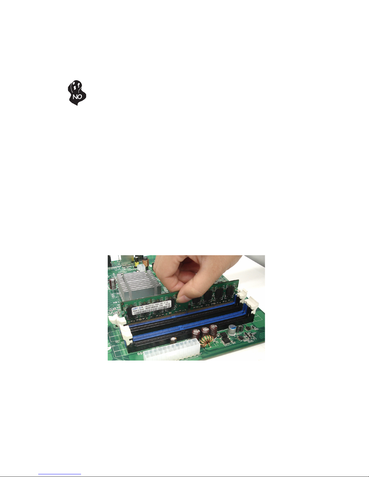
Refer to the following to install the memory modules.
1 This motherboard supports unbuffered DDR4 2133 SDRAM .
2 Push the latches on each side of the DIMM slot down.
3 Align the memory module with the slot. The DIMM slots are keyed with
notches and the DIMMs are keyed with cutouts so that they can only be
installed correctly.
4 Check that the cutouts on the DIMM module edge connector match the
notches in the DIMM slot.
5 Install the DIMM module into the slot and press it firmly down until it
seats correctly. The slot latches are levered upwards and latch on to
the edges of the DIMM.
6 Install any remaining DIMM modules.
* For reference only
Installing Memory Modules
This motherboard accommodates two memory modules. It can support DDR4 2133
(1GB/ 2GB/ 4GB/ 8GB). The total memory capacity is 16 GB.
Do not remove any memory module from its antistatic packaging until
you are ready to install it on the motherboard. Handle the modules only
by their edges. Do not touch the components or metal parts. Always wear
a grounding strap when you handle the modules.
Page 20
17
Installing the Motherboard
Installing Add-on Cards
The slots on this motherboard are designed to hold expansion cards and connect them
to the system bus. Expansion slots are a means of adding or enhancing the
motherboard’s features and capabilities. With these efficient facilities, you can increase the motherboard’s capabilities by adding hardware that performs tasks that are
not part of the basic system.
Before installing an add-on card, check the documentation for
the card carefully. If the card is not Plug and Play, you may
have to manually configure the card before installation.
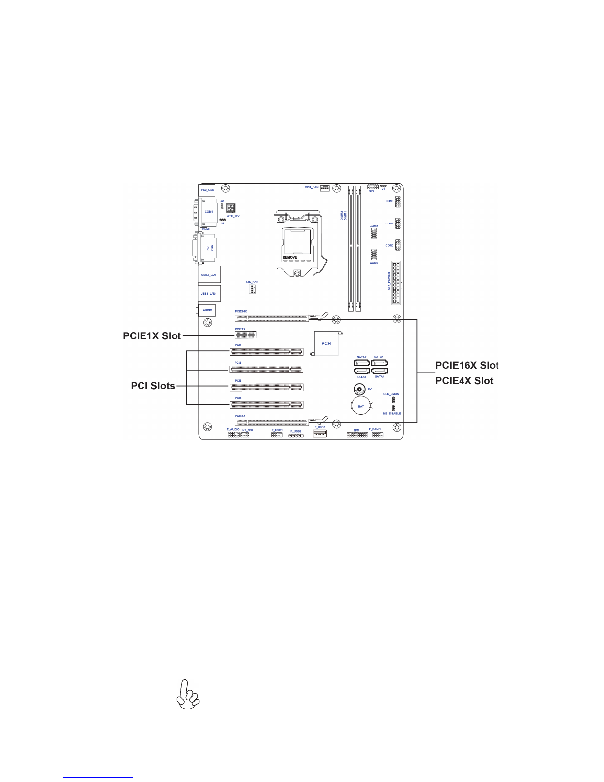
Expansion Slots
PCIE Slot
The PCI Express x1 slot is fully compliant to the PCI Express
Base Specification revision 2.0.
The PCI Express x16 slot is used to install an external PCI
Express graphics card that is fully compliant to the PCI Express
Base Specification revision 3.0.
PCIE16X Slot
This motherboard is equipped with four standard PCI slots. PCI
stands for Peripheral Component Interconnect and is a bus standard for expansion cards, which for the most part, is a supplement of the older ISA bus standard. The PCI slots on this board
are PCI v2.2 compliant.
PCI1~4 Slots
The PCI Express x4 slot is used to install an external PCI
Express graphics card that is fully compliant to the PCI Express
Base Specification revision 3.0.
PCIE4X Slot
Page 21
18
Installing the Motherboard
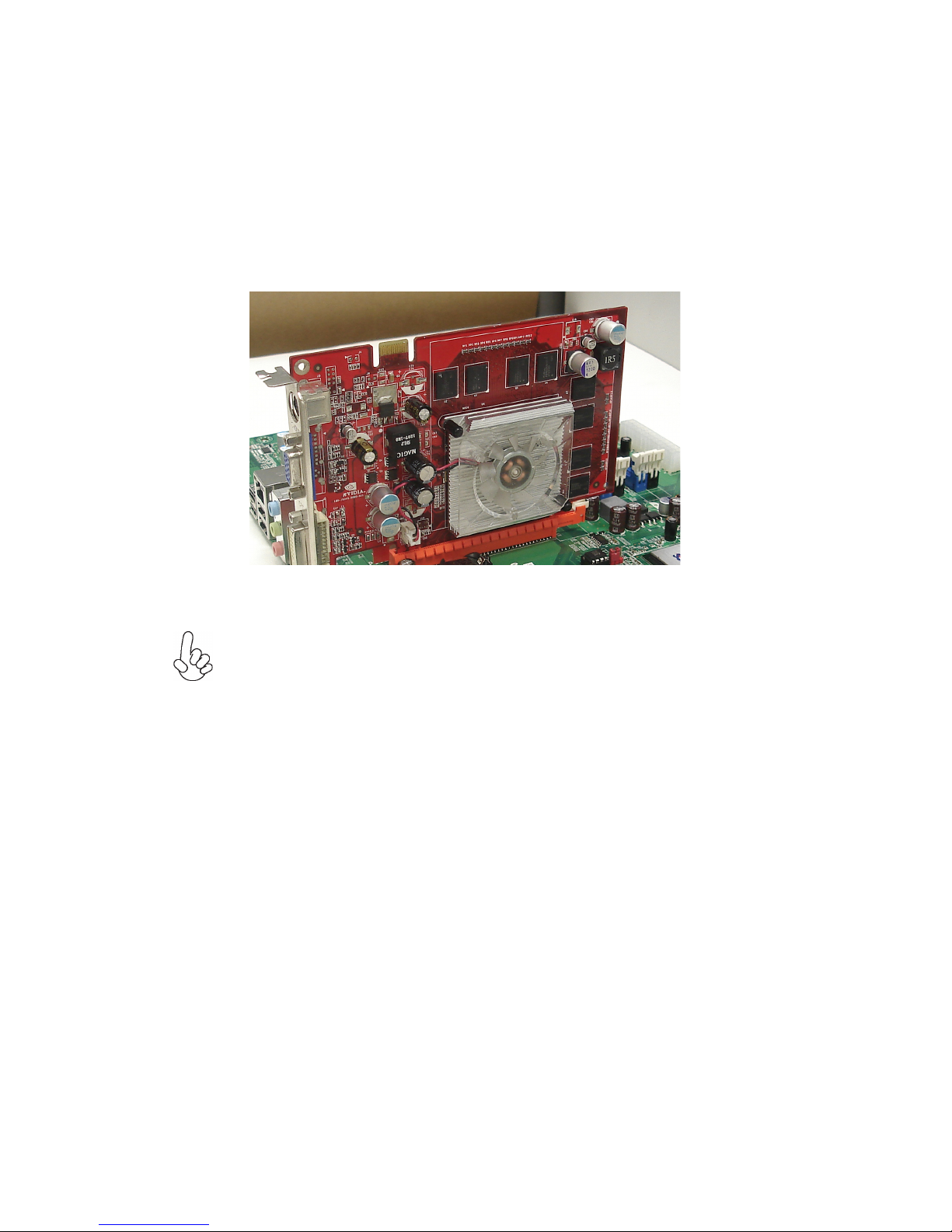
Follow these instructions to install an add-on card:
1 Remove a blanking plate from the system case corresponding to the
slot you are going to use.
2 Install the edge connector of the add-on card into the expansion slot.
Ensure that the edge connector is correctly seated in the slot.
3 Secure the metal bracket of the card to the system case with a screw.
For some add-on cards, for example graphics adapters and network adapters, you have to install drivers and software before you can begin using the
add-on card.
* For reference only
Page 22
19
Installing the Motherboard
Connecting Optional Devices
Refer to the following for information on connecting the motherboard’s optional
devices:
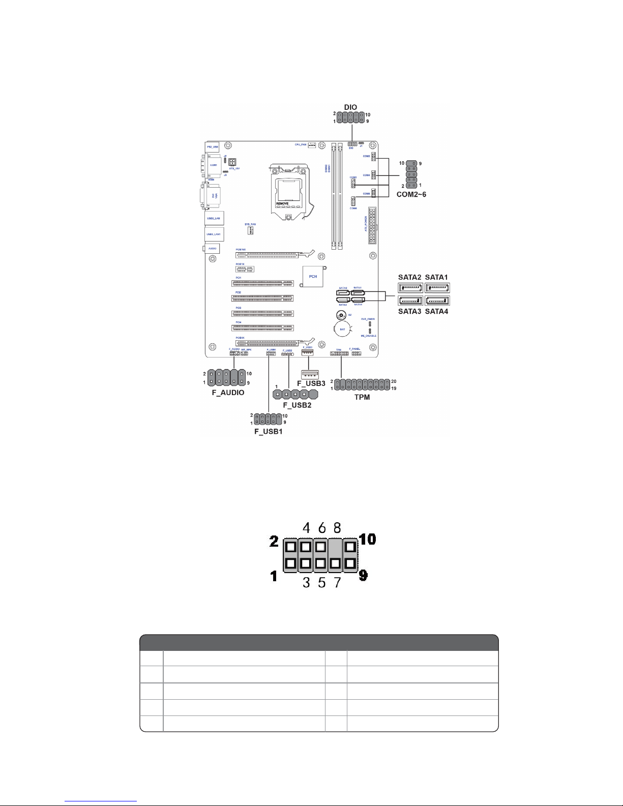
The front panel audio header allows the user to install auxiliary front-oriented
microphone and line-out ports for easier access. This header supports HD audio by
default. If you want connect an AC
’ 97 front panel audio to HD onboard headers,
please set as below picture.
F_AUDIO: Front Panel Audio Header
For HD Front Audio
9 Left channel to front panel
10
Line-in sensor detect
2 Analog groud
4 HD Panel sensor detect
6 Microphone sensor detect
8 No pi n
Pin Description
1 Left channel microphone input signal
3 Right channel microphone input signal
5 Right channel to front panel
7 Analog ground
Pin Description
Page 23
20
Installing the Motherboard
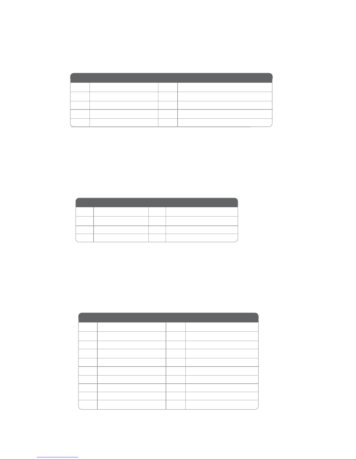
SATA1~4: Serial ATA 6.0Gb/s connector
This connector is used to support the Serial ATA devices for the highest data transfer
rates (6.0 Gb/s), simpler disk drive cabling and easier PC assembly.
1
Ground
2
TX+
3
TX-
4
Ground
5
RX-
6
RX+
7
Ground
8
No pin
Pin Signal Name
Pin Signal Name
TPM: Trusted Platform Module header
Trusted platform module (TPM) is a published specification detailing a
microcontrollerthat can store secured information, and implementations of that
specification.
1
TPM_CLK
11
LAD0
2
GND
12
GND
3
LFRAME#
13
RESERVE0
4
No pin
14
RESERVE1
5
LREST#
15
VCC3_DUAL
6
SMBDATA
16
SERIRQ
7
LAD3
17
GND
8
LAD2
18
GND
9
VCC3
19
LPCPD#
10
LAD1
20
SMBCLK
Pin Signal Name Pin Signal Name
COM2~6 : Onboard serial port headers
Connect a serial port extension bracket to this header to add a second serial port to
your system.
1 Data Carrier Detect 6 Data Set Ready
2 Serial Input 7 Request to Send
3 Serial Output 8 Clear to Send
4 Data Terminal Ready 9 Ring Indicator
5 Ground 10 No pin
Pin Signal Name Pin Signal Name
Page 24
21
Installing the Motherboard
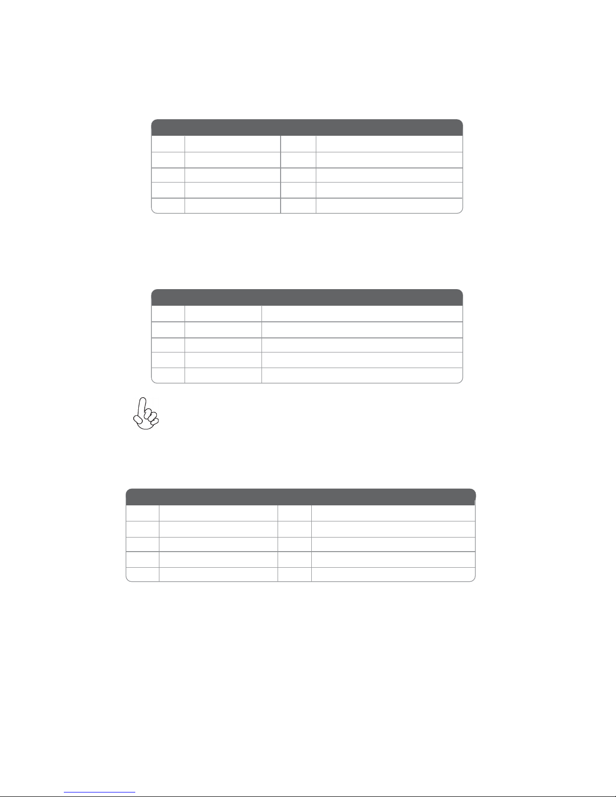
Please make sure that the USB cable has the same pin assignment as
indicated above. A different pin assignment may cause damage or system
hang-up.
F_USB1: Front Panel USB 2.0 header
The onboard F_USB1~3 header delegate for card reader, it supports additonal six
USB 2.0 ports.
1
Power +5V 6 USB Port B (+)
2
Power +5V 7 Ground
3
USB Port A (-) 8 Ground
4
USB Port B (-) 9 No pin
5
USB Port A (+) 10 Not Connected
Pin Signal Name Pin Signal Name
DIO: 4 bit GPIO header
F_USB2: Front Panel USB 2.0 header
The onboard F_USB header delegate for card reader, it supports additonal one USB
2.0 port.
1
USBPWR Front Panel USB Power
2
DATA- USB Port Negative Signal
3
DATA+ USB Port Positive Signal
4
GND Ground
5
No pin No pin
Pin Signal Name Function
1 GPIO3 6 GPIO5
2 GPIO7 7 GPIO0
3 GPIO2 8 GPIO4
4 GPIO6 9 +5VSB
5 GPIO1 10 GND
Pin Signal Name Pin Signal Name
Page 25
22
Installing the Motherboard
Installing a SATA Hard Drive
This section describes how to install a SATA Hard Drive.
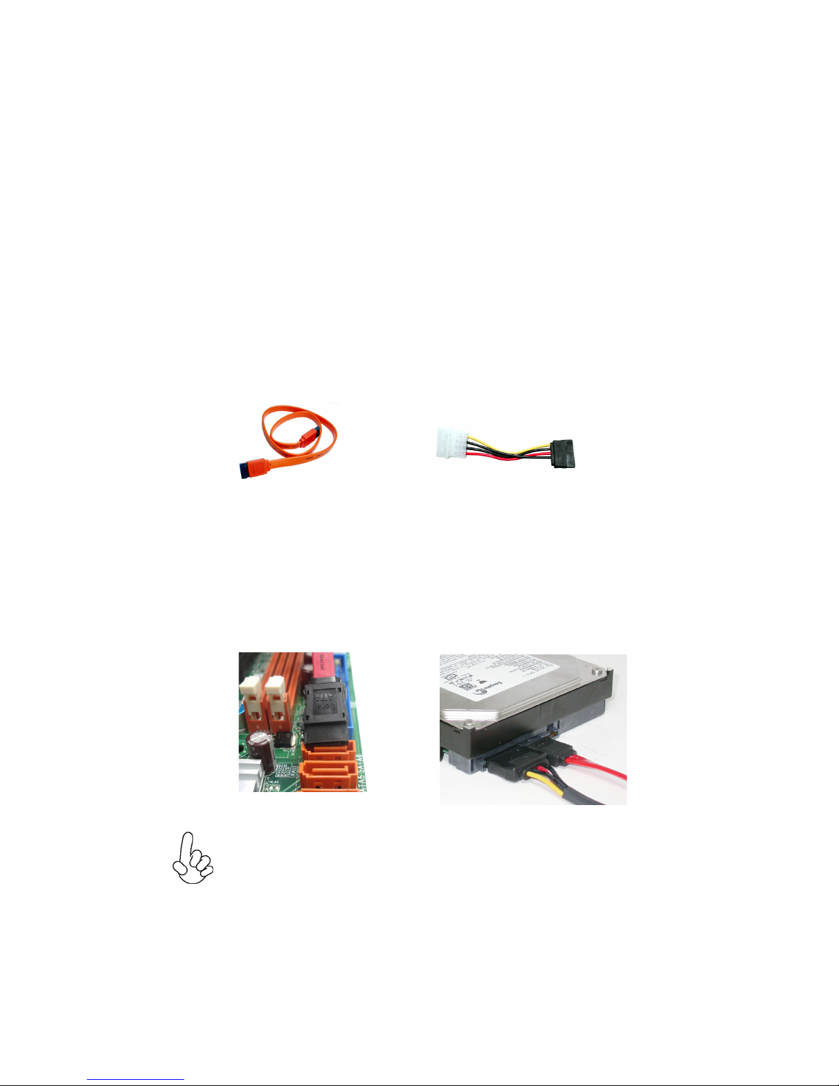
SATA cable
(optional)
SATA power cable
(optional)
About SATA Connectors
Your motherboard features four SATA connectors supporting a total of four drives.
SATA refers to Serial ATA (Advanced Technology Attachment) is the standard interface for the IDE hard drives which are currently used in most PCs. These connectors
are well designed and will only fit in one orientation. Locate the SATA connectors on
the motherboard and follow the illustration below to install the SATA hard drives.
Installing Serial ATA Hard Drives
To install the Serial ATA (SATA) hard drives, use the SATA cable that supports the
Serial ATA protocol. This SATA cable comes with a SATA power cable. You can
connect either end of the SATA cable to the SATA hard drive or the connector on the
motherboard.
Refer to the illustration below for proper installation:
This motherboard supports the “Hot-Plug” function.
1 Attach either cable end to the connector on the motherboard.
2 Attach the other cable end to the SATA hard drive.
3 Attach the SATA power cable to the SATA hard drive and connect the
other end to the power supply.
* For reference only
Page 26
23
Installing the Motherboard
Connecting I/O Devices
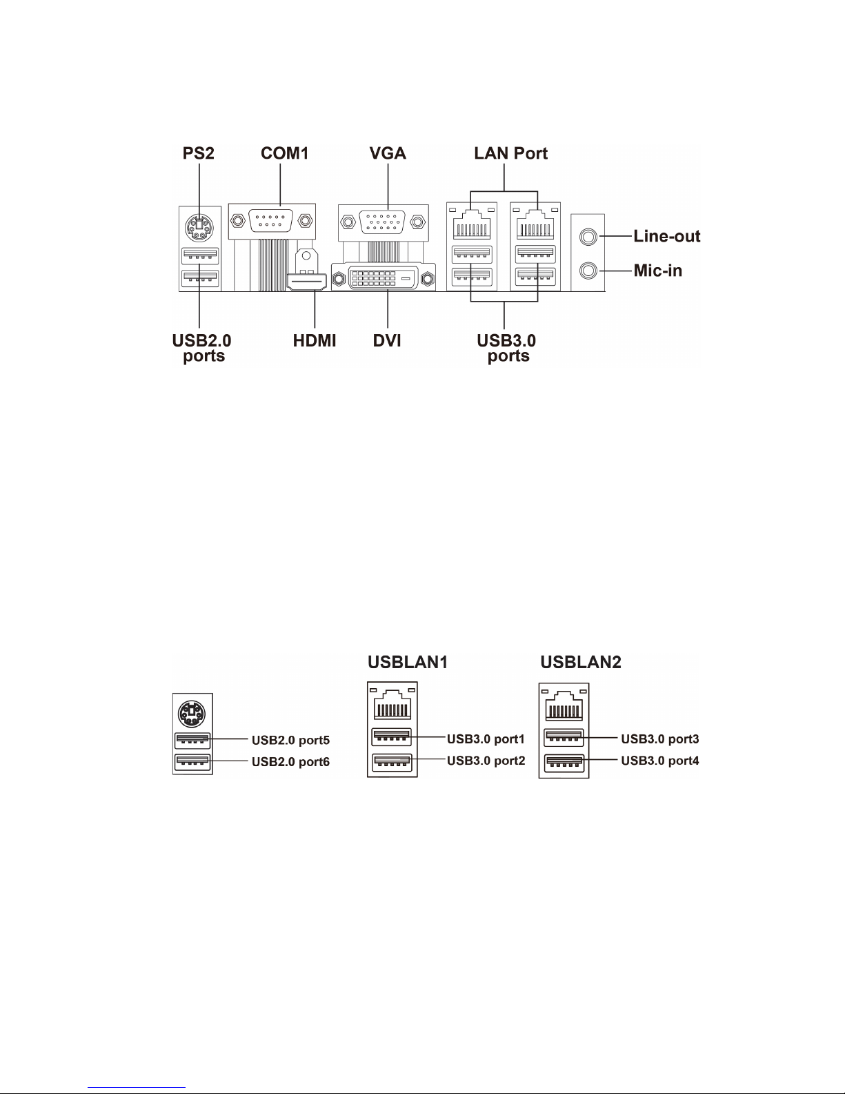
The backplane of the motherboard has the following I/O ports:
LAN Ports
Connect an RJ-45 jack to the LAN port to connect your
computer to the Network.
Audio Ports
Use the two audio ports to connect audio devices. The first
jack is for stereo line-out singal. The second jack is for
stereo Mic-in singal.
PS2 Mouse Use the upper PS2 port to connect a PS/2 pointing device
or keyboard.
You can connect the display devices to the VGA port.
VGA Port
You can connect the display devices to the DVI port.
DVI Port
Serial port
(COM1)
Use the COM port to connect the serial devices such as mice
or fax/modems.
Use the USB 3.0 ports to connect USB 3.0 devices.
USB 3.0 Ports
You can connect the cash drawer to the HDMI port.
HDMI Port
Use the USB 2.0 ports to connect USB 2.0 devices.
USB 2.0 Ports
Page 27
24
Installing the Motherboard
Connecting Case Components
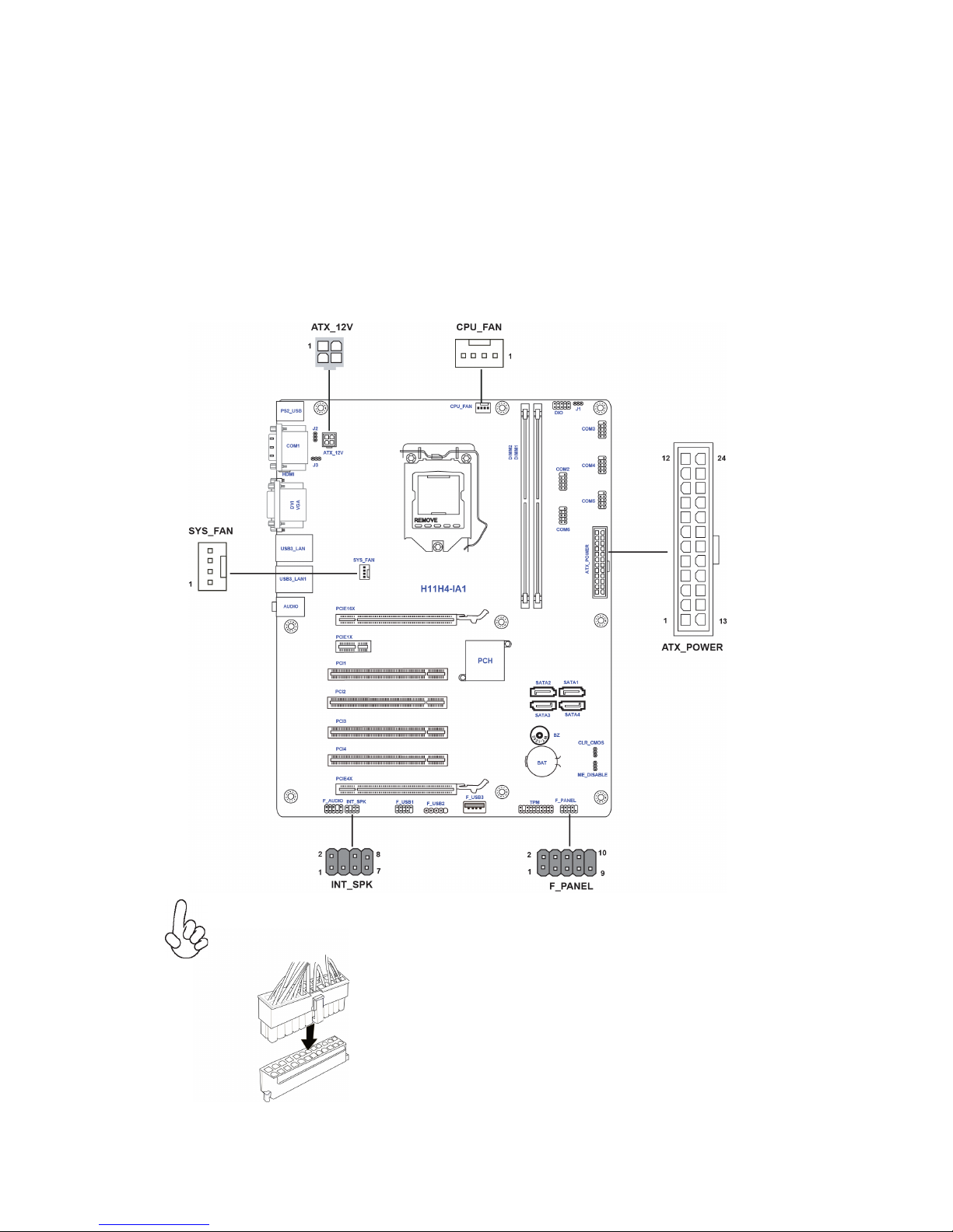
After you have installed the motherboard into a case, you can begin connecting the
motherboard components. Refer to the following:
1 Connect the CPU cooling fan connector to CPU_FAN.
2 Connect the system cooling fan connector to SYS_FAN.
3 Connect the standard power supply connector to ATX_POWER.
4 Connect the case switches and indicator LEDs to the F_PANEL.
5 Connect the case speaker cable to INT_SPK.
6 Connect the auxiliary case power supply connector to ATX_12V.
The ATX 24-pin connector allows you to connect to ATX v2.x power supply.
With ATX v2.x power supply, users please
note that when installing 24-pin power
cable, the latches of power cable and the
ATX match perfectly.
Connecting 24-pin power cable
24-pin power cable
Page 28
25
Installing the Motherboard
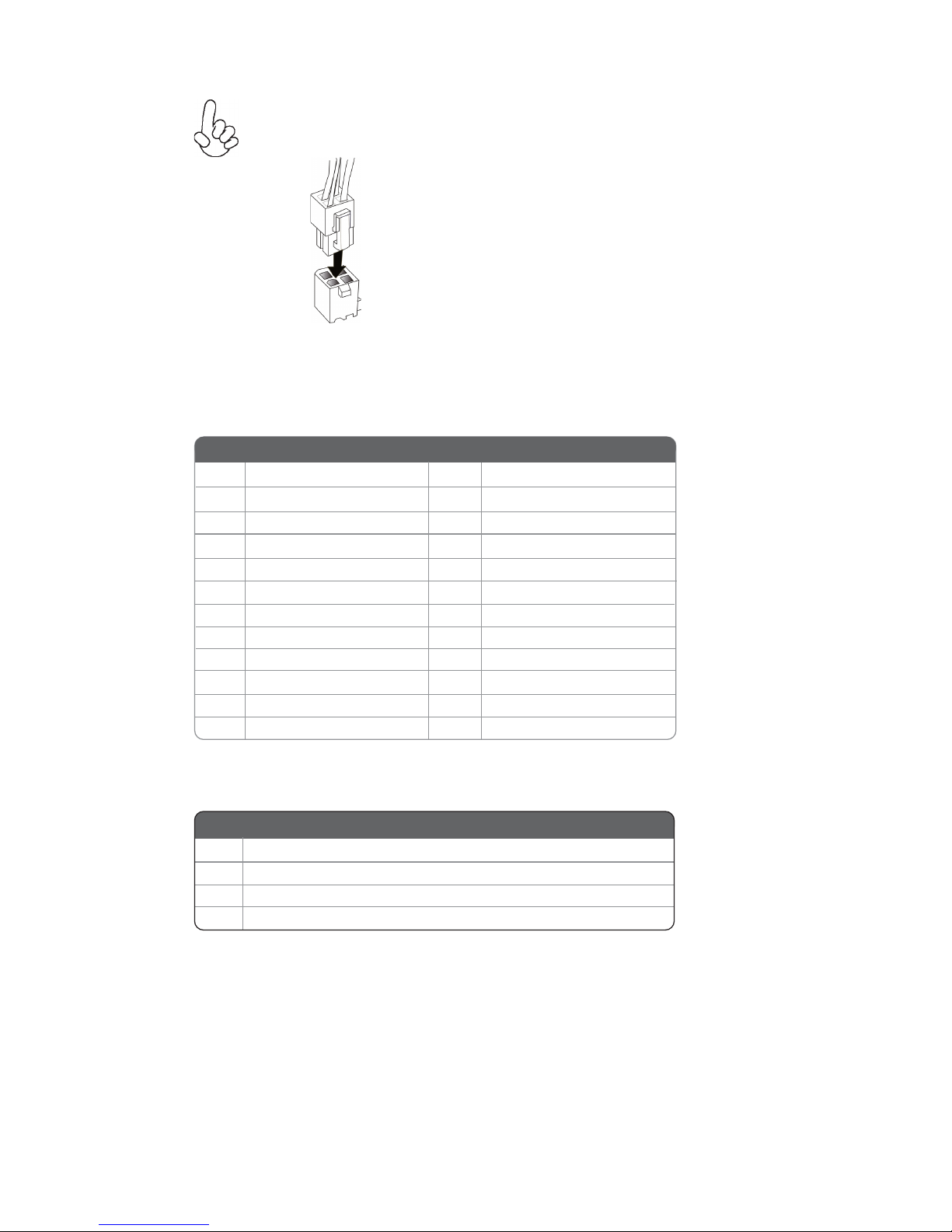
The ATX12V4P power connector is used to provide power to the CPU.
When installing 4-pin power cable, the
latches of power cable and the ATX12V4P
match perfectly.
Connecting 4-pin power cable
4-pin power cable
Pin Signal Name Pin Signal Name
1 +3.3V 13 +3.3V
2 +3.3V 14 -12V
3 Ground 15 Ground
4 +5V 16
PS_ON
5 Ground 17
Ground
6 +5V 18
Ground
7 Ground 19
Ground
8 PWRGD 20
-5V
9 +5VSB 21
+5V
10 +12V
22
+5V
11 +12V 23
+5V
12 +3.3V 24
Ground
ATX_POWER
ATX_12V
1
Ground
2
Ground
3
+12V
4
+12V
Pin Signal Name
Page 29
26
Installing the Motherboard
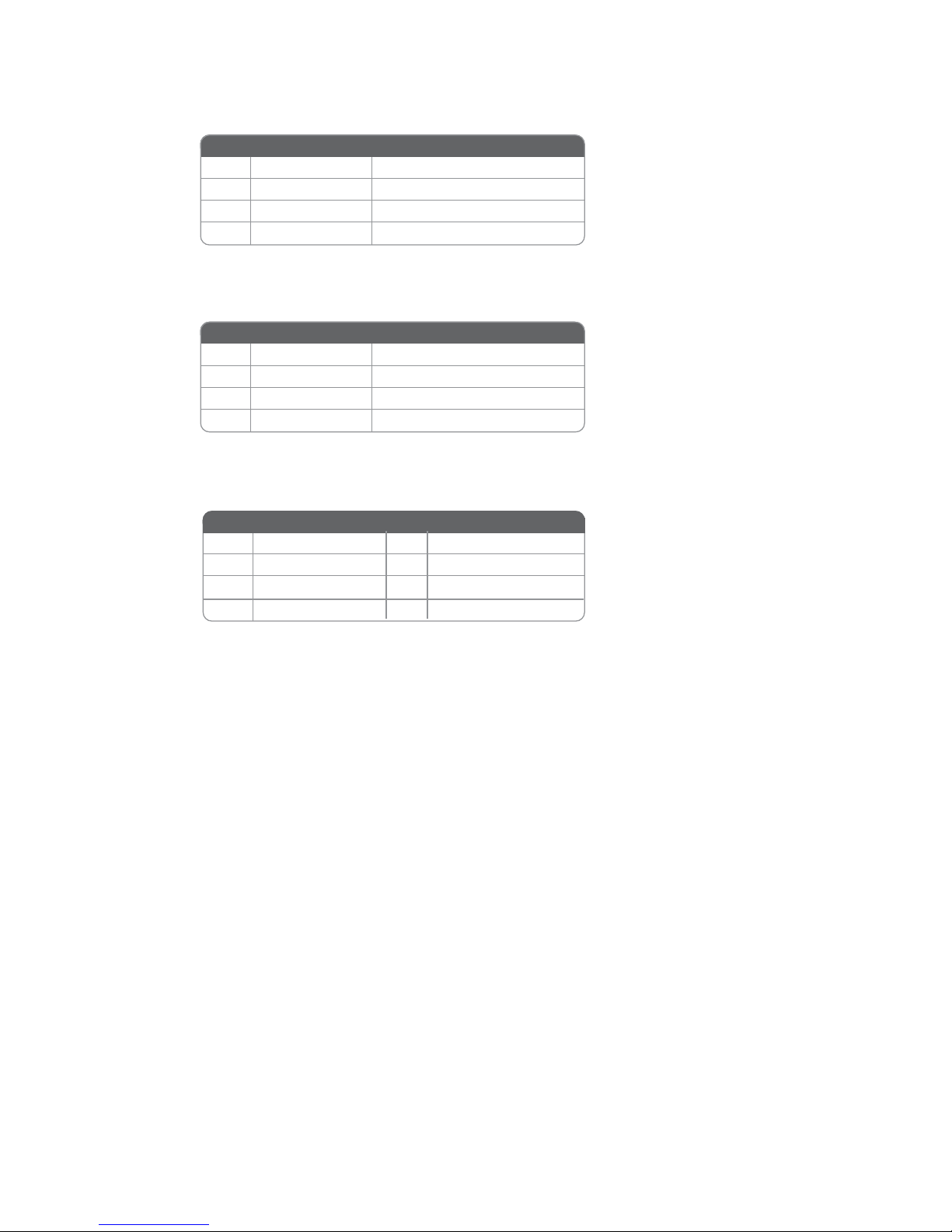
INT_SPK: Internal speaker
1
Output_L
3 Output_R
4 GND
2
GND
Pin Signal Name Pin Signal Name
SYS_FAN: System Cooling FAN Power Connectors
1
GND
System Ground
3 Sense Sensor
4 CONTROL CONTROL
Pin Signal Name Function
2 +12V Power +12V
CPU_FAN: CPU Cooling FAN Power Connectors
1
GND
System Ground
3 Sense Sensor
4 CONTROL CONTROL
Pin Signal Name Function
2
+12V
Power +12V
5
GND
6
GND
7
+3.3V
8
VC C
Page 30
27
Installing the Motherboard
Hard Drive Activity LED
Connecting pins 1 and 3 to a front panel mounted LED provides visual indication
that data is being read from or written to the hard drive. For the LED to function
properly, an IDE drive should be connected to the onboard IDE interface. The LED
will also show activity for devices connected to the SCSI (hard drive activity LED)
connector.
Power/Sleep/Message waiting LED
Connecting pins 2 and 4 to a single or dual-color, front panel mounted LED provides
power on/off, sleep, and message waiting indication.
Reset Switch
Supporting the reset function requires connecting pin 5 and 7 to a momentarycontact switch that is normally open. When the switch is closed, the board resets and
runs POST.
Power Switch
Supporting the power on/off function requires connecting pins 6 and 8 to a momentary-contact switch that is normally open. The switch should maintain contact for at
least 50 ms to signal the power supply to switch on or off. The time requirement is
due to internal de-bounce circuitry. After receiving a power on/off signal, at least two
seconds elapses before the power supply recognizes another on/off signal.
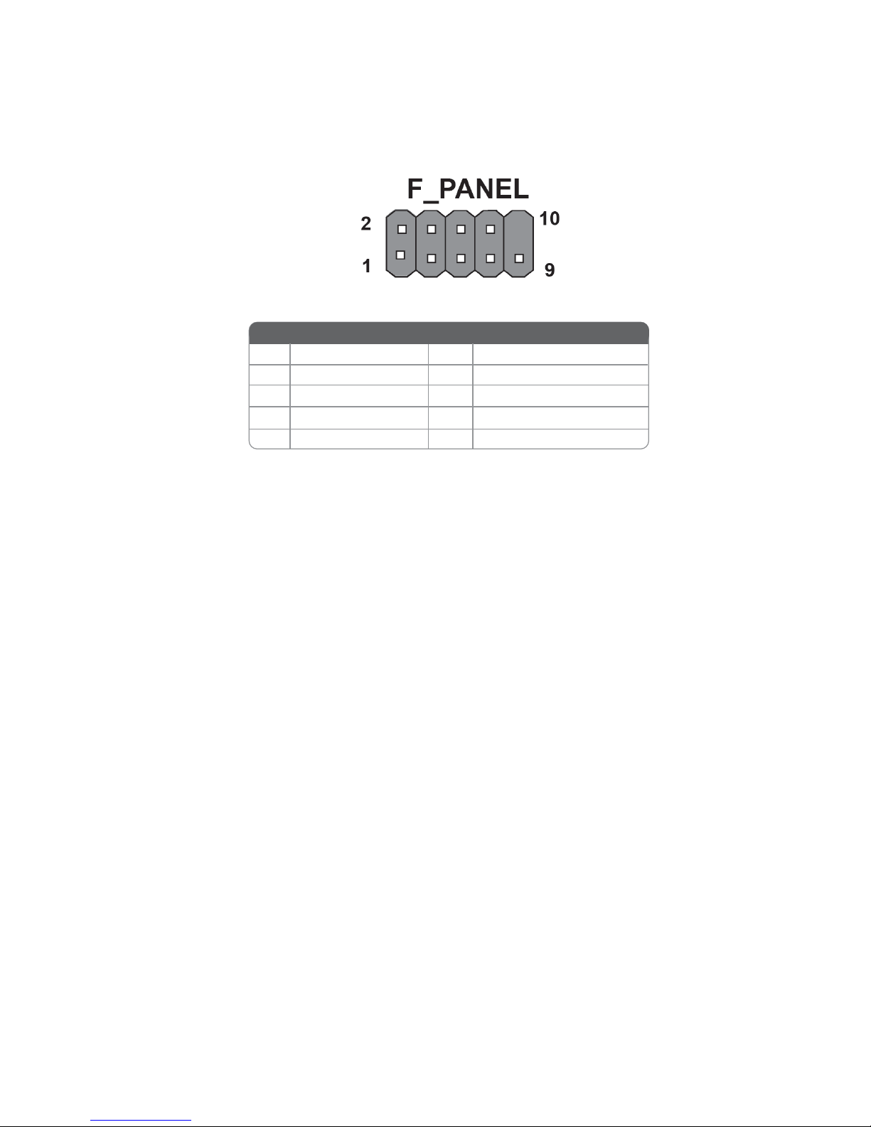
Front Panel Header
The front panel header (F_PANEL) provides a standard set of switch and LED
headers commonly found on ATX or Micro ATX cases. Refer to the table below for
information:
* MSG LED (dual color or single color)
Pin Signal Pin Signal
1
Hard disk LED (+)
6
Power Switch (+)
2 MSG LED (+) 7 Reset Switch (+)
3
Hard disk LED (-)
8
Power Switch (-)
4
MSG LED (-)
9
Reserved
5
Reset Switch (-)
10
No pin
Page 31
28
Installing the Motherboard
Note:
Wake Up on LAN Driver Status S0 S3 S4 S5
Access Blink Blink Blink Blink
Not Access OFF OFF OFF OFF
Disconnected OFF
1000: Amber ON
100: Green ON
10: OFF OFF
OFF
BIOS Default
Wake Up on LAN
=Enabled
Default
(Wak e on LA N
Disabled)
Active LED
Speed LED OFF OFF
Wake Up on LAN Driver Status S0 S3 S4 S5
Access Blink Blink Blink OFF
Not Access OFF OFF OFF OFF
Disconnected OFF
1000: Amber ON
100: Green ON
10: OFF OFF
OFF
BIOS Default
Res ume b y
PME /LAN1
=Disabled
Default
(Wak e on LA N
Disabled)
Active LED
Speed LED OFF OFF
1. Intel I219 LAN PHY, EUP enable, S5 can wake up.
2. Intel I211 EUP enable, S5 cannot wake up.
Page 32

39
Using BIOS
Press <Esc> to return to the Advanced Menu page.
Limit CPUID Maximum (Disabled)
Use this item to enable or disable the maximum CPUID value limit, you can enable
this item to prevent the system from “rebooting” when trying to install Windows
NT4.0.
Execute Disabled Bit (Enabled)
This item allows the processor to classify areas in memory by where application
code can excute and where in cannot. When a malicious worm attempts to insert
code in the buffer, the processor disables code excution, preventing damage or worm
propagation. Replacing older computers with Excute Disable Bit enabled systems
can halt worm attacks, reducing the need for virus related repair.
Intel Vitualization Technology (Enabled)
When disabled, a VMM cannot utilize the additional hardware capabilities provided
by Vandor Pool Technology.
Package C State limit (AUTO)
Use this item to set package C state limit.
Enhanced Halt (C1E)
Use this item to enable or disable the Enhanced C1 state.
Hardware P states (HWP (Disabled)
Use this item to enable or disable the Hardware P states.
 Loading...