

Page 1

USER'S MANUAL
Rev: 1.0
Release date: May 30, 2016
Of
Intel H81 Express Chipset
Based
M/B for LGA 1150 Quad Core Ready
Intel Core Processor
Trademark:
* Specifications and Information contained in this documentation are furnished for information use only, and are
subject to change at any time without notice, and should not be construed as a commitment by manufacturer.
Page 2

ii
ENVIRONMENTAL SAFETY INSTRUCTION................................................................................ iii
ENVIRONMENTAL PROTECTION ANNOUCEMENT.................................................................. iii
USER’S NOTICE............................................................................................................................... iv
MANUAL REVISION INFORMATION............................................................................................. iv
ITEM CHECKLIST............................................................................................................................. iv
CHAPTER 1 INTRODUCTION OF THE MOTHERBOARD
1-1 SPECIFICATION................................................................................................................ 1
1-2 LAYOUT DIAGRAM.......................................................................................................... 2
CHAPTER 2 HARDWARE INSTALLATION
2-1 JUMPER SETTING............................................................................................................ 5
2-2 CONNECTORS AND HEADERS..................................................................................... 7
2-2-1 REAR I/O BACK PANEL CONNECTORS
.......................................................
7
2-2-2 MOTHERBOARD INTERNAL CONNECTORS............................................... 8
2-2-3 HEADER PIN DEFINITION................................................................................ 10
CHAPTER 3 INTRODUCING BIOS
3-1 ENTERNING SETUP
.........................................................................................................
15
3-2 BIOS MENU SCREEN.......................................................................................................15
3-3 FUNCTION KEYS.............................................................................................................. 16
3-4 GETTING HELP................................................................................................................. 16
3-5 MENU BARS...................................................................................................................... 17
3-6 MAIN MENU....................................................................................................................... 17
3-7 ADVANCED MENU
...........................................................................................................
18
3-8 CHIPSET MENU.................................................................................................................24
3-9 BOOT MENU...................................................................................................................... 27
3-10 SECURITY MENU.............................................................................................................. 28
3-11 SAVE & EXIT MENU......................................................................................................... 28
TABLE OF CONTENT
Page 3
Environmental Safety Instruction
Avoid the dusty, humidity and temperature extremes. Do not place the product in
0 to 40 centigrade is the suitable temperature. (The figure comes from the request
Generally speaking, dramatic changes in temperature may lead to contact
The increasing temperature of the capacitor may decrease the life of computer.
Attention to the heat sink when you over-clocking. The higher temperature may
any area where it may become wet.
of the main chipset)
malfunction and crackles due to constant thermal expansion and contraction from
the welding spots’ that connect components and PCB. Computer should go
through an adaptive phase before it boots when it is moved from a cold
environment to a warmer one to avoid condensation phenomenon. These water
drops attached on PCB or the surface of the components can bring about
phenomena as minor as computer instability resulted from corrosion and oxidation
from components and PCB or as major as short circuit that can burn the
components. Suggest starting the computer until the temperature goes up.
Using the close case may decrease the life of other device because the higher
temperature in the inner of the case.
decrease the life of the device and burned the capacitor.
Environmental Protection Announcement
Do not dispose this electronic device into the trash while discarding. To minimize
pollution and ensure environment protection of mother earth, please recycle.
iii
Page 4

USER’S NOTICE
Motherboard
User’s Manual
DVD for motherboard utilities
Cable(s)
I/O Back panel shield
COPYRIGHT OF THIS MANUAL BELONGS TO THE MANUFACTURER. NO PART OF THIS MANUAL,
INCLUDING THE PRODUCTS AND SOFTWARE DESCRIBED IN IT MAY BE REPRODUCED, TRANSMITTED
OR TRANSLATED INTO ANY LANGUAGE IN ANY FORM OR BY ANY MEANS WITHOUT WRITTEN
PERMISSION OF THE MANUFACTURER.
THIS MANUAL CONTAINS ALL INFORMATION REQUIRED TO USE THIS MOTHER-BOARD SERIES AND WE
DO ASSURE THIS MANUAL MEETS USER’S REQUIREMENT BUT WILL CHANGE, CORRECT ANY TIME
WITHOUT NOTICE. MANUFACTURER PROVIDES THIS MANUAL “AS IS” WITHOUT WARRANTY OF ANY
KIND, AND WILL NOT BE LIABLE FOR ANY INDIRECT, SPECIAL, INCIDENTAL OR CONSEQUENTIAL
DAMAGES (INCLUDING DAMAGES FOR LOSS OF PROFIT, LOSS OF BUSINESS, LOSS OF USE OF DATA,
INTERRUPTION OF BUSINESS AND THE LIKE).
PRODUCTS AND CORPORATE NAMES APPEARING IN THIS MANUAL MAY OR MAY NOT BE
REGISTERED TRADEMARKS OR COPYRIGHTS OF THEIR RESPECTIVE COMPANIES, AND THEY ARE
USED ONLY FOR IDENTIFICATION OR EXPLANATION AND TO THE OWNER’S BENEFIT, WITHOUT
INTENT TO INFRINGE.
Manual Revision Information
Reversion Revision History Date
1.0 First Edition May 30, 2016
Item Checklist
iv
Page 5

Introduction of the Motherboard
Spec
Description
Design
ATX form factor; PCB size: 24.5 x 30.5 cm
Chipset
Intel®H81 Express Chipset
CPU Socket
Supports Intel®Core™ i7, Core™ i5, Core™ i3 series,
Pentium®processor in LAG1150 Package
* for detailed CPU support information please visit our website
Memory Slots
2* DDRIII RAM module slot
Supporting 2 * DDRIII 1600/1333 MHz RAM Module
expandable to 16GB
Support dual-channel function
Expansion Slots
1 * PCI-Express x16 slot (PE1)
2 * PCI-Express x 1 slot (PE2/3)
4 *32-bit PCI slot (PCI1/2/3/4)
Storage
2 * SATAIII 6Gb/s port (SATA1/2)
1 * SATAII 3Gb/s port (SATA5)
1 * Full-size M-SATA slot (MSATA)
LAN Chips
Integrated 2* Intel®i211ATGigabit Ethernet LAN chip that
supports Fast Ethernet LAN function of providing
10/100/1000Mbps Ethernet data transfer rate
HD Audio Chip
4-CH HD Audio Codec integrated
Audio driver and utility included
BIOS
64M Bit DIP Flash ROM
Multi I/O
Rear Panel I/O:
1*PS/2 keyboard & mouse combo connector
2* VGA port connector
1* DVI-D port connector
1* HDMI port connector
2*RJ-45 LAN connector
2* USB 2.0 port connector
4* USB 3.0 port connector
1*3-jack audio connector (Line-in; Line-out; MIC)
Internal I/O Connectors& Headers:
1 *24-pin main power connector
1 *8-pin 12V Power connector
1* vertical USB 2.0 port connector (USB20_V)
1* Front panel audio header
1* Front panel header
2* USB 2.0 header(support 4*expansion USB 2.0 port)
1*LAN activity LED header
1* GPIO header
1* SM_BUS header
2* 9-pin RS232/422/485 serial port header (COM1/2)
2* RS232 serial port expansion block (COM3-6/COM7-10)
1* Parallel port header (LPT)
1*CPU fan header & 2*System fan header
1-1 Specification
Chapter 1
1
Page 6
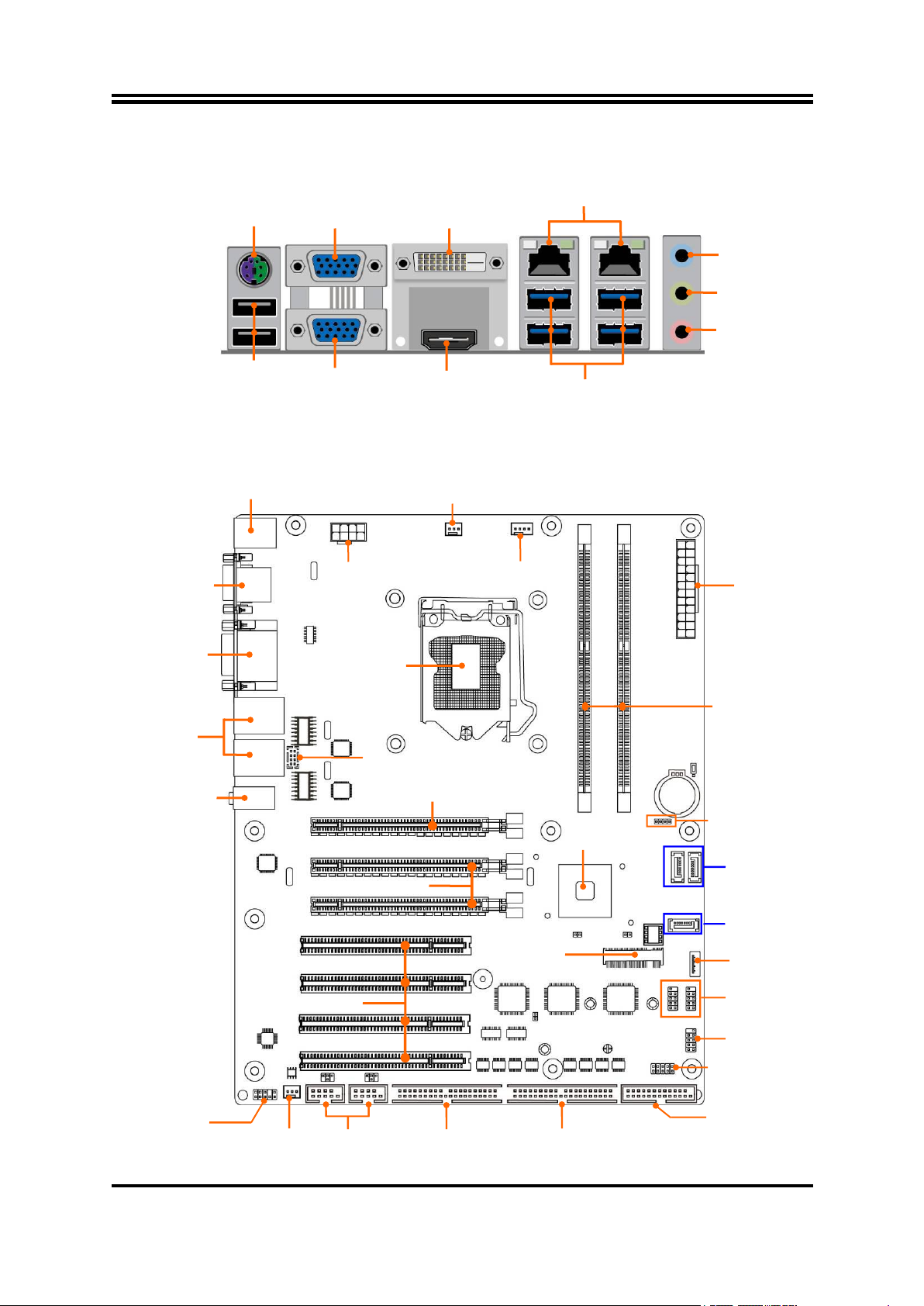
1-2 Layout Diagram
RJ-45 LAN Ports
USB 2.0 Ports
Line-IN
Line-OUT
MIC-IN
USB 3.0 Ports
VGA1 Port
DVI-D Port
HDMI Port
PS/2 KB & MS
Combo Port
VGA2 Port
ATX Power
Connector
DDRIII
DIMM Slot x 2
VGA Ports
PCI Express x16 Slot (PE1)
32-bit PCI Slots
ATX 12V
Power Connector
SYS FAN1 Header
CPUFAN Header
LGA 1150
CPU Socket
Intel H81
Chipset
Full-size
MSATA Slot
(MSATA)
USB 2.0 Port
Headers
SATAII Port
(SATA5)
DVI–D Port
Over HDMI Port
RJ-45 LAN Ports
Over USB 3.0 Ports
Audio Connectors
SM_BUS Header
USB 2.0 Port
Connector
PS/2 KB&MS Combo Port
Over USB 2.0 Ports
GPIO Header
Parallel Port Header
Serial Port Headers
(COM1/2)
Serial Port
Expansion Block
(COM3-6)
Front Panel Header
Front Panel
Audio Header
SYSFAN2
Header
LAN Activity LED Header
Serial Port
Expansion Block
(COM7-10)
SATAIII Ports
(SATA1/2)
Rear IO Diagram
Motherboard Internal Diagram
2
Page 7
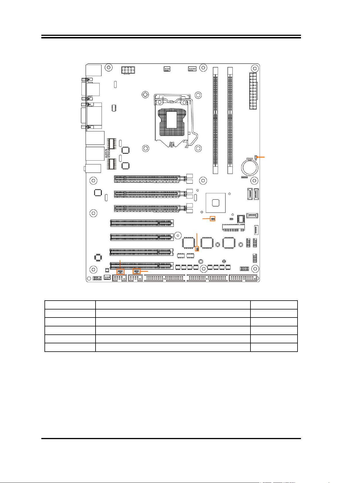
Motherboard Jumper Position
Jumper
Jumper
Name
Description
JPCOM1
COM1 Header Pin9 Function Select
4-pin Block
JPCOM2
COM2 Header Pin9 Function Select
4-pin Block
JBAT
Clear CMOS RAM Function Setting
3-pin Block
JPME
ME Features Select
2-pin Block
AT_MODE
AT Mode/ ATX Mode Select
2-pin Block
JBAT
JPCOM1
AT_MODE
JPME
JPCOM2
3
Page 8
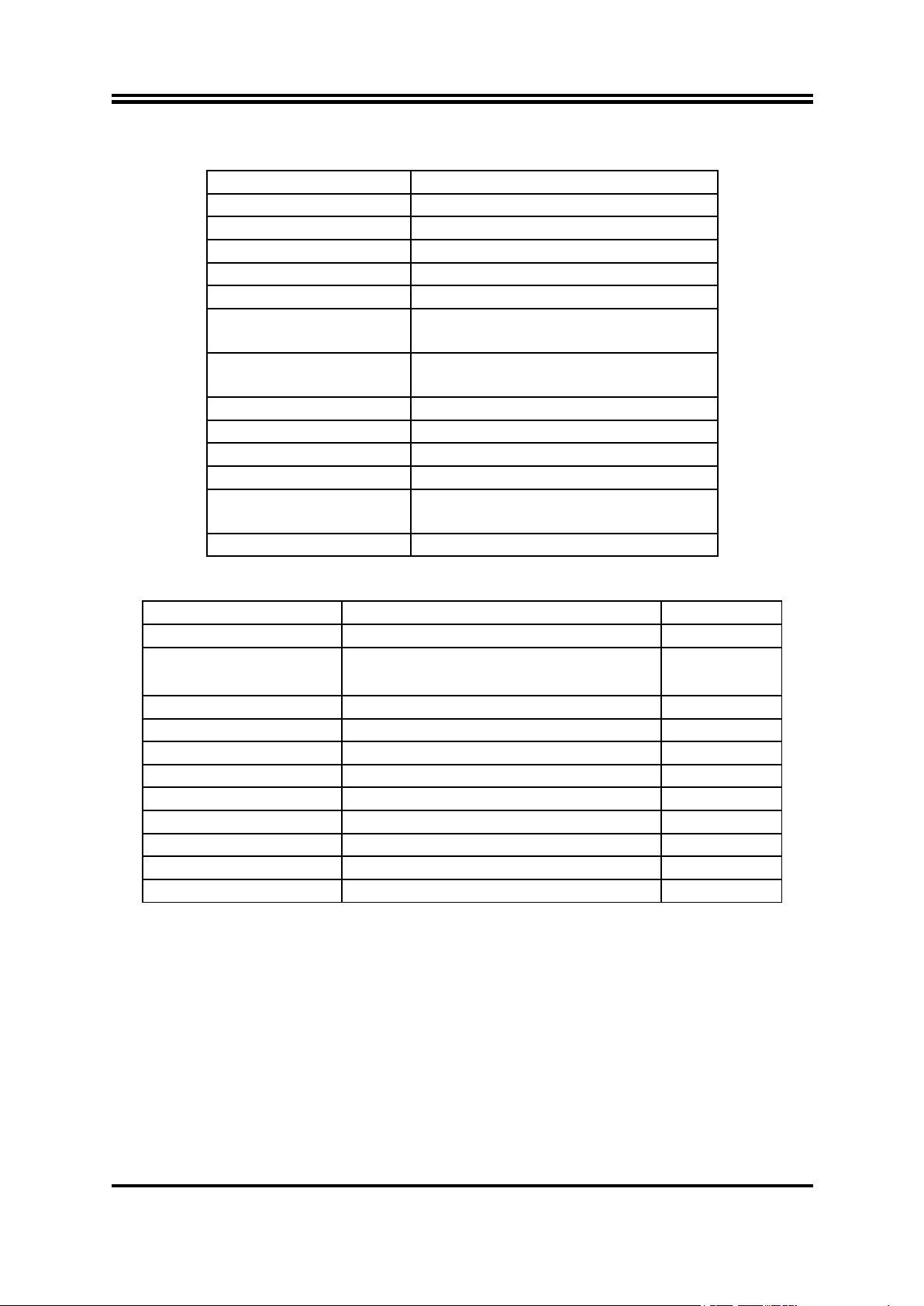
Connectors
Connector
Name
ATXPWR
ATX Power Connector
ATX12V
ATX 12V Power Connector
SATA1/2
SATAIII Connector x2
SATA5
SATAII Connector
USB20_V
Internal USB 2.0 Port Connector
USB_PS2 (Top)
PS/2 Keyboard & Mouse
Combo Port Connector
USB_PS2
(Middle & Bottom)
USB 2.0 Port Connector x2
VGA1/2
VGA Port Connector x2
DVI
DVI-D Port Connector
HDMI
High Definition Multimedia Interface
UL1(Top)/UL2(Top)
RJ-45 LAN Connector x2
UL1(Middle & Bottom)
/UL2(Middle & Bottom)
USB 3.0 Port Connector x4
AUDIO
Line-out ; Line In; MIC Connector
Headers
Header
Name
Description
FP_AUDIO
Front Panel Audio Header
9-pin Block
JW_FP
(Front Panel Header)
PWR LED/ HD LED/ /Power Button
/Reset
9-pin Block
USB3/USB4
USB 2.0 Header
9-pin Block
LAN_LED
LAN Activity LED Header
8-pin Block
GPIO
GPIO Header
10-pin Block
SM_BUS
SMBUS Header
4-pin Block
COM1/ 2
Serial Port Header
9-pin Block
COM3-6/COM7-10
Serial Port Header Expansion Block
39-pin Block
LPT
Parallel Port Header
25-pin Block
SYSFAN1/SYSFAN2
System FAN Header
3-pin Block
CPUFAN
CPU FAN Header
4-pin Block
4
Page 9
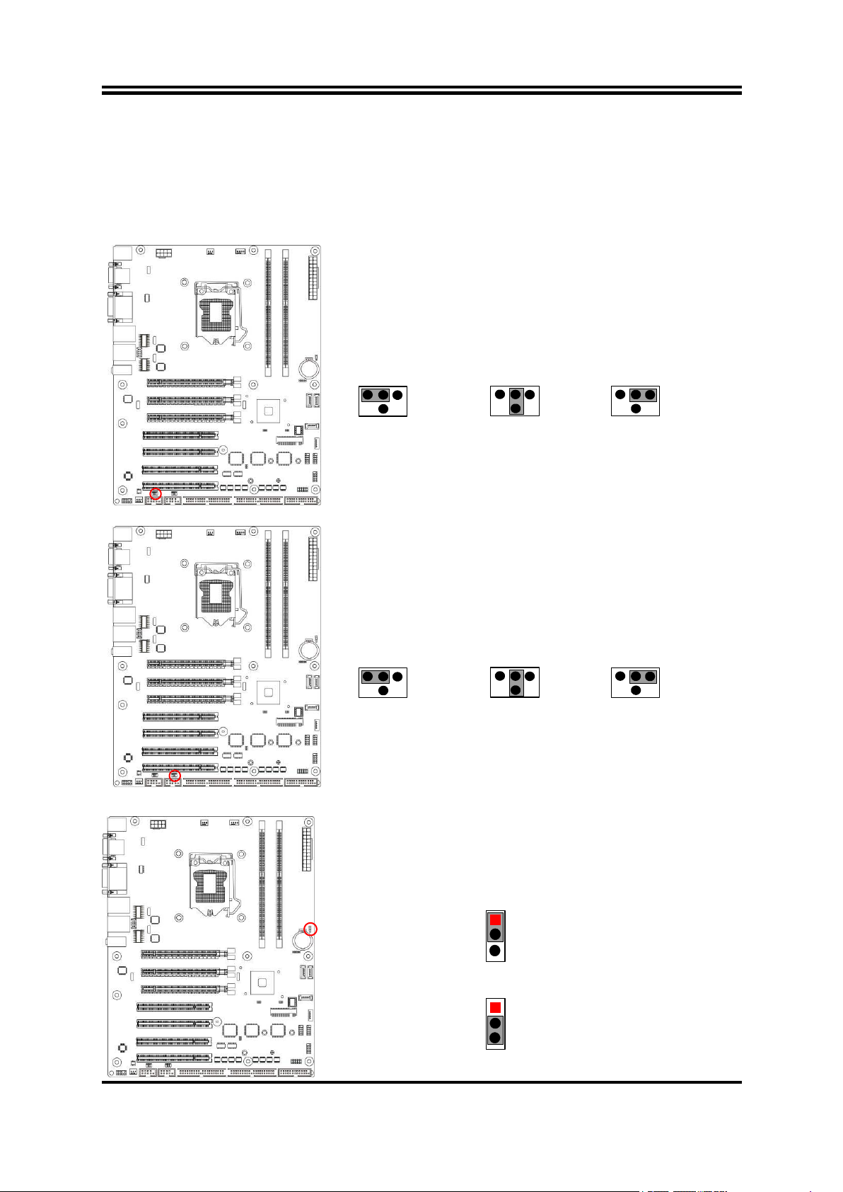
Chapter 2
JP1→ COM1 Header
4-6 Closed:
Pin9=12V;
6 4 2
3-4 Closed:
Pin9= 5V;
2-4 Closed:
Pin9=RI;
3 1 5
1
3
5 2 4
6
1
3 5 2 4 6
JPCOM2→COM 2 Header
4-6 Closed:
Pin9=12V.
6 4 2
3-4 Closed:
Pin9=5V;
2-4 Closed:
Pin9=RI;
3 1 5
1
3
5 2 4
6
1
3 5 2 4 6
2-3 Closed: Clear CMOS.
JBAT→Clear CMOS
1-2 Closed: Normal;
1
3
1
3
Hardware Installation
2-1 Jumper Setting
JPCOM1 (4-pin): COM1 Header Pin9 Function Select
JPCOM2 (4-pin): COM2 Header Pin9 Function Select
JBAT (3-pin): Clear CMOS Function Settings
5
Page 10

JPME (2-pin): ME Features Select
1-2 Closed:ME Features Disabled.
JPME→ME Features
1
2
1-2 Open:ME Features Enabled(Normal);
1
2
Pin1
Pin1
AT_MODE→AT/ATX Mode Select
1-2 Open: ATX Mode Selected (Default);
1-2 Closed: AT Mode Selected.
AT_MODE (2-pin): AT Mode / ATX Mode Select
*ATX Mode Selected: Press power button to power on after power input ready;
AT Mode Selected: Directly power on as power input ready.
6
Page 11
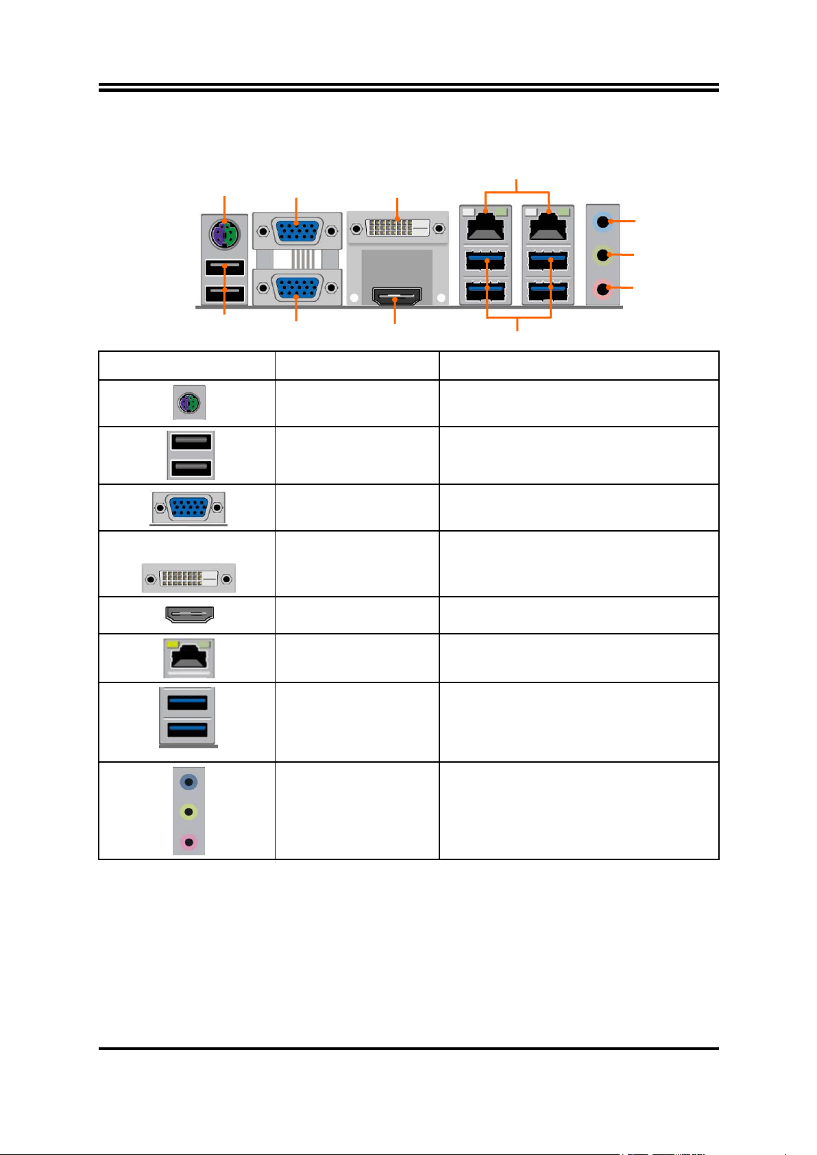
2-2 Connectors and Headers
Icon
Name
Function
PS/2 Keyboard & Mouse
Combo Port
For user to connect PS/2 keyboard or PS/2
mouse device to the board.
USB 2.0 Port
To connect USB keyboard, mouse or other
devices compatible with USB specification.
VGA Port
To connect display device that support VGA
specification.
DVI-D Port
To connect display device that support DVI-D
specification
HDMI
Port
To connect display device that support HDMI
specification.
RJ-45 LAN Port
This connector is standard RJ-45 LAN jack
for Network connection.
USB 3.0 Port
To connect USB keyboard, mouse or other
devices compatible with USB specification.
USB 3.0 ports supports up to 5Gbps data
transfer rate.
3-jack
Audio Connector
BLUE : Line-in Connector
GREEN:Line-out Connector
PINK : MIC Connector
RJ-45 LAN Ports
USB 2.0 Ports
Line-IN
Line-OUT
MIC-IN
USB 3.0 Ports
VGA1 Port
DVI-D Port
HDMI Port
PS/2 KB & MS
Combo Port
VGA2 Port
2-2-1 Rear I/O Back Panel Connectors
7
Page 12
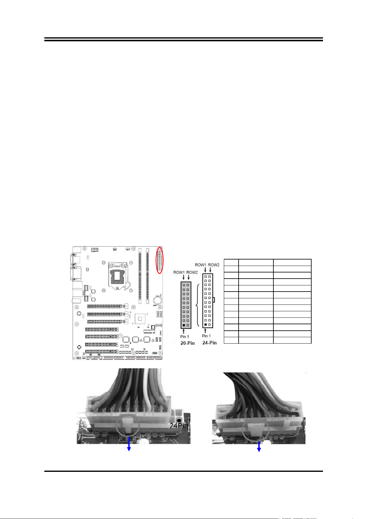
2-2-2 Motherboard Internal Connectors
PIN
ROW1
ROW2
1
+3.3V
+3.3V
2
+3.3V
-12V
3
GND
GND
4
+5V
Soft Power on
5
GND
GND
6
+5V
GND
7
GND
GND
8
Power OK
-5V
9
+5V Stand by
+5V
10
+12V
+5V
11
+12V
+5V
12
+3.3V
GND
24-pin Main Power Connector
(1) ATXPWR (24-pin block): Main Power Connector
ATX Power Supply connector: This is a new defined 24-pins connector that
usually comes with ATX case. The ATX Power Supply allows using soft power
on momentary switch that connect from the front panel switch to 2-pins Power
On jumper pole on the motherboard. When the power switch on the back of the
ATX power supply turned on, the full power will not come into the system board
until the front panel switch is momentarily pressed. Press this switch again will
turn off the power to the system board.
** We recommend that you use an ATX 12V Specification 2.0-compliant power
supply unit (PSU) with a minimum of 350W power rating. This type has 24-pin
and 4-pin power plugs.
** If you intend to use a PSU with 20-pin and 4-pin power plugs, make sure that the
20-pin power plug can provide at least 15A on +12V and the power supply unit
has a minimum power rating of 350W. The system may become unstable or may
not boot up if the power is inadequate.
** If you are using a 20-pin power plug, please refer to Figure1 for power supply
connection. Power plug form power supply and power connectors from
motherboard both adopt key design to avoid mistake installation. You can insert
the power plug into the connector with ease only in the right direction. If the
direction is wrong it is hard to fit in and if you make the connection by force if is
possible.
Figure1:20-pin power plug Figure 2:24-pin power plug
8
Page 13
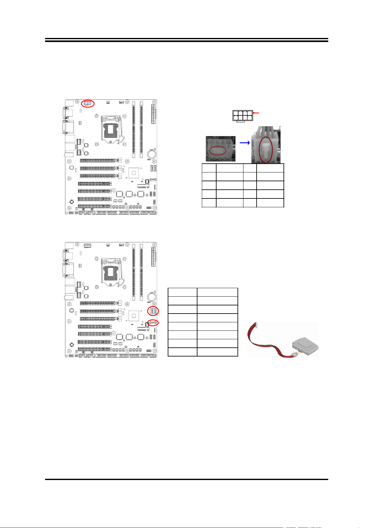
(2) ATX12V (8-pin block): 12V Power Connector
Pin1
4
Pin
Definition
No.
Definition
1
GND
5
+12V
2
GND
6
+12V
3
GND
7
+12V
4
GND
8
+12V
Pin No.
Definition
1
GND
2
TXP
3
TXN
4
GND
5
RXN
6
RXP
7
GND
This is a new defined 8-pin connector that usually comes with ATX Power Supply that
supports extra 12V voltage to maintain system power consumption. Without this
connector might cause system unstable because the power supply can not provide
sufficient current for system.
(3) SATA1/2/5(7-pin): SATAIII Port connector
SATA1 & SATA2 are high-speed SATAIII ports that support 6 GB/s transfer rate.
SATA5 is SATAII port that support 3 GB/s transfer rate.
9
Page 14
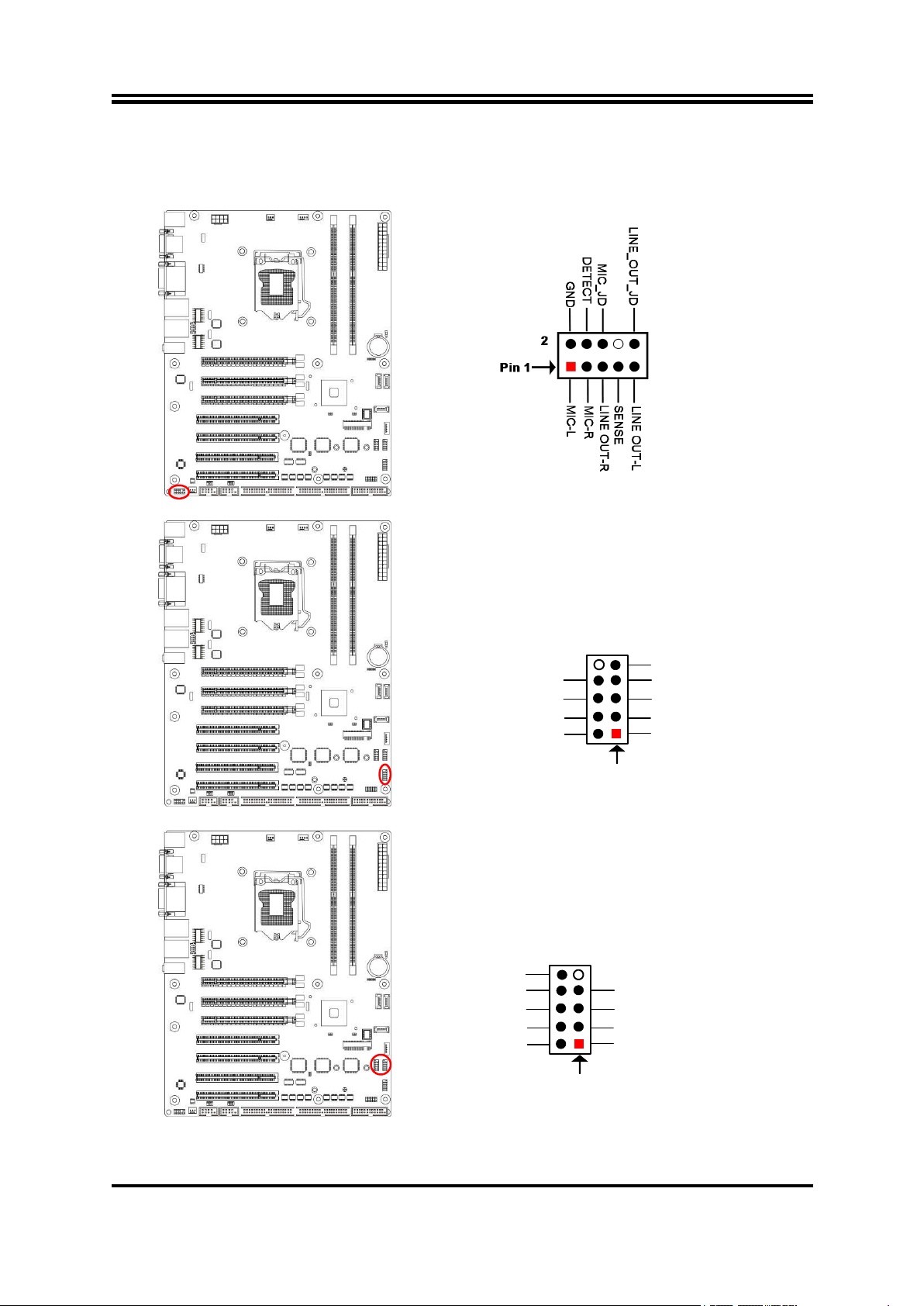
2-2-3 Header Pin Definition
HDD LED+
GND
HDD LED-
GND
RSTSW
PWRBTN
Pin 1
2
VCC
PWR LED+
PWR LED -
VCC
-DATA
GND
+DATA
Pin 1
2
VCC
-DATA
+DATA
GND
NC
FP_AUDIO (9-pin): Line-Out, MIC-In Header
This header is connected to Front Panel Line-out, MIC connector with cable.
JW_FP (9-pin): Front Panel Header
USB3/USB4 (9-pin): USB 2.0 Port Header
10
Page 15
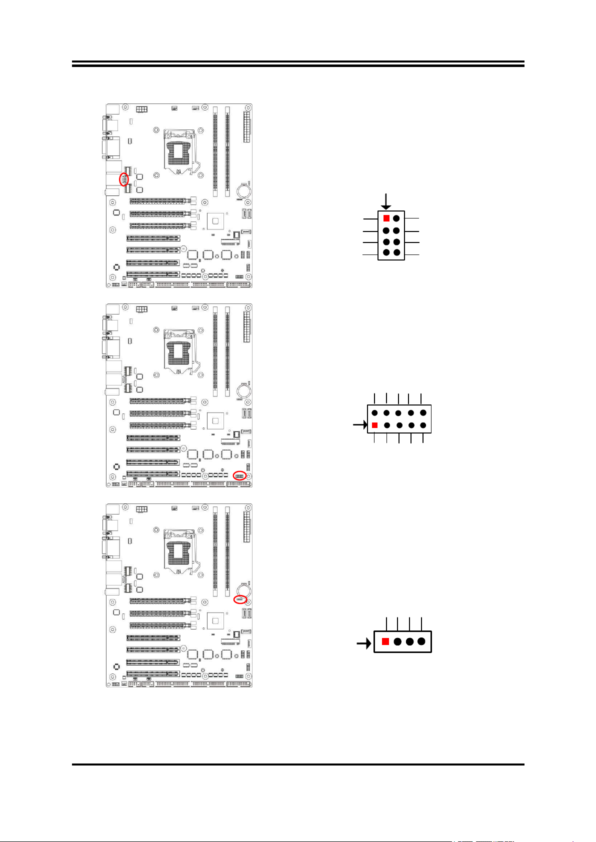
LAN_LED (8-pin): LAN1 & LAN2 Activity LED Header
Pin 1
7
LAN1_ACT+
LAN1_100M-
LAN2_ACT+
LAN2_100M-
LAN1_ACT-
LAN1_1G-
LAN2_ACT-
LAN2_1G-
2
8
GPIO_80
Pin1
2
GPIO_82
GPIO_84
GPIO_86
GND
GPIO_81
GPIO_83
GPIO_85
GPIO_87
VCC
Pin 1
VCC
SMBUS_
CLK
SMBUS_DATA
GND
GPIO (10-pin): GPIO Header
SM_BUS (4-pin): SM BUS Header
11
Page 16
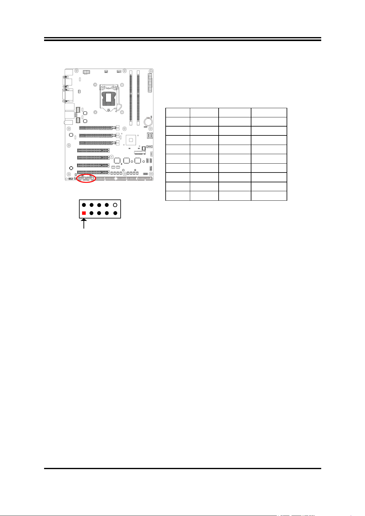
COM1/COM2 (9-Pin): RS232/422/485 Serial Port Header
2
Pin 1
3 4 5
6
7
8
9
Pin NO.
RS232
*RS422
*RS485
Pin 1
DCD
TX-
DATA-
Pin 2
RXD
TX+
DATA+
Pin 3
TXD
RX+
NC
Pin 4
DTR
RX-
NC
Pin 5
GND
GND
GND
Pin 6
DSR
NC
NC
Pin 7
RTS
NC
NC
Pin 8
CTS
NC
NC
Pin 9
RI
NC
NC
*Notice: COM1 & COM2 ports server as RS232 serial port header in most
cases.RS422 & RS485 function is only optional to customized models. User also
needs to go to BIOS to set ‘Transmission Mode Select’ for COM1/2 as [RS422] or
[RS485] for boards that support RS422/485 function before connecting compatible
COM cable to COM1/2 header.
12
Page 17
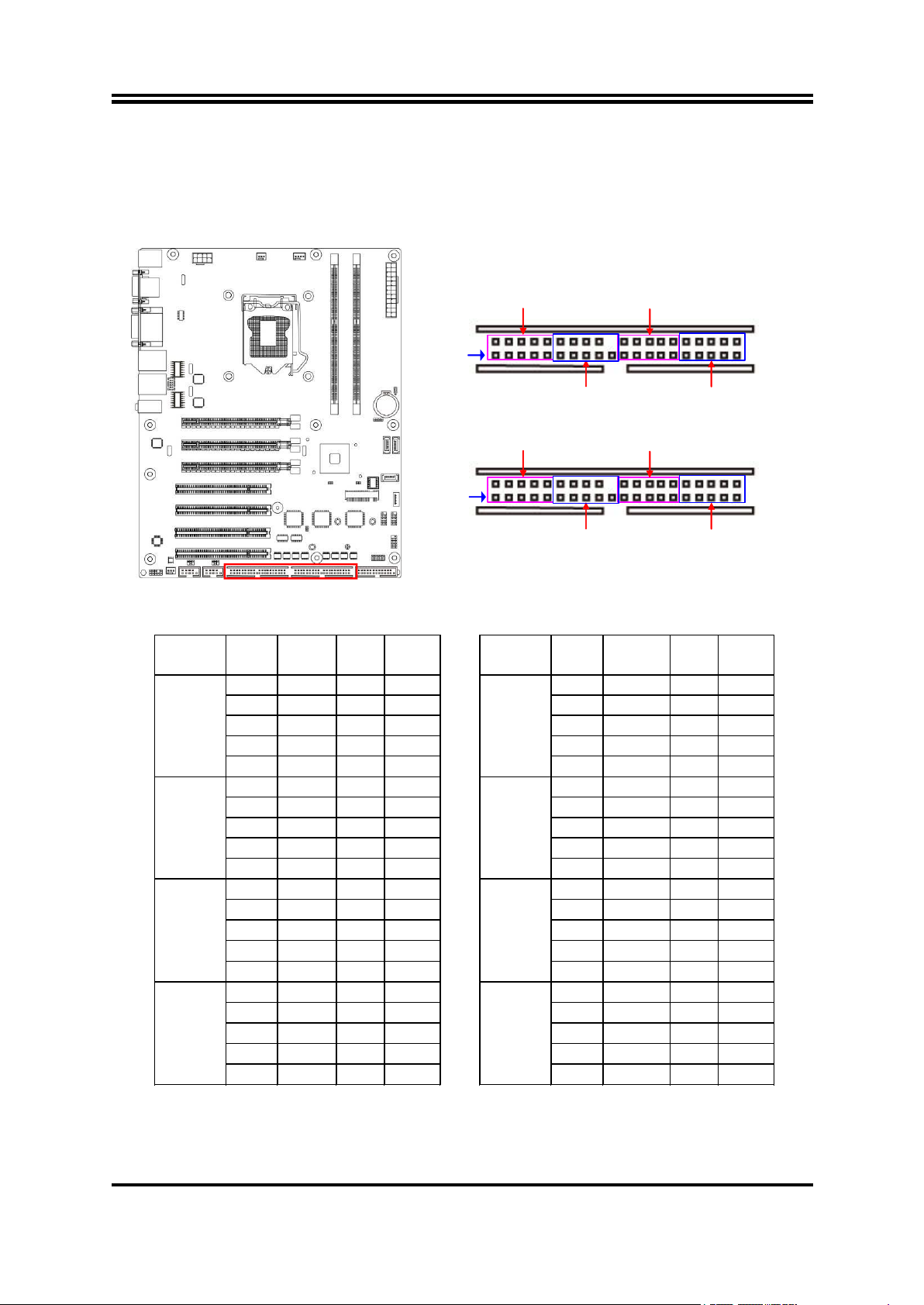
COM3-6/COM7-10 (39-Pin): RS232 Serial Port Header Expansion Block
COM3-6
COM3
COM4
COM5
COM6
COM7
COM8
COM9
COM10
COM7-10
Pin 1
2
39
40
Pin 1
2
39
40
COM3-6
Pin
NO.
RS232
Pin
NO.
RS232
Pin 1
DCD3
Pin 2
DSR3
Pin3
SIN3
Pin 4
RTS3
Pin 5
SOUT3
Pin 6
CTS3
Pin 7
DTR3
Pin 8
RI3
COM3
Pin 9
GND
Pin 10
GND
Pin 11
DCD4
Pin 12
DSR4
Pin 13
SIN4
Pin 14
RTS4
Pin 15
SOUT4
Pin 16
CTS4
Pin 17
DTR4
Pin 18
RI4
COM4
Pin 19
GND
Pin 20
N/A
Pin 21
DCD5
Pin 22
DSR5
Pin 23
SIN5
Pin 24
RTS5
Pin 25
SOUT5
Pin 26
CTS5
Pin 27
DTR5
Pin 28
RI5
COM5
Pin 29
GND
Pin 30
GND
Pin 31
DCD6
Pin 32
DSR6
Pin 33
SIN6
Pin 34
RTS6
Pin 35
SOUT6
Pin 36
CTS6
Pin 37
DTR6
Pin 38
RI6
COM6
Pin 39
GND
Pin 40
GND
COM7-10
Pin
NO.
RS232
Pin
NO.
RS232
Pin 1
DCD7
Pin 2
DSR7
Pin3
SIN7
Pin 4
RTS7
Pin 5
SOUT7
Pin 6
CTS7
Pin 7
DTR7
Pin 8
RI7
COM7
Pin 9
GND
Pin 10
GND
Pin 11
DCD8
Pin 12
DSR8
Pin 13
SIN8
Pin 14
RTS8
Pin 15
SOUT8
Pin 16
CTS8
Pin 17
DTR8
Pin 18
RI8
COM8
Pin 19
GND
Pin 20
N/A
Pin 21
DCD9
Pin 22
DSR9
Pin 23
SIN9
Pin 24
RTS9
Pin 25
SOUT9
Pin 26
CTS9
Pin 27
DTR9
Pin 28
RI9
COM9
Pin 29
GND
Pin 30
GND
Pin 31
DCD10
Pin 32
DSR10
Pin 33
SIN10
Pin 34
RTS10
Pin 35
SOUT10
Pin 36
CTS10
Pin 37
DTR10
Pin 38
RI10
COM10
Pin 39
GND
Pin 40
GND
COM3-6 & COM7-10 are RS232 serial port header expansion blocks each composed
of 4* RS232 serial port headers (COM3-6 by COM3/4/5/6; COM7-10 by
COM7/8/9/10).
13
Page 18
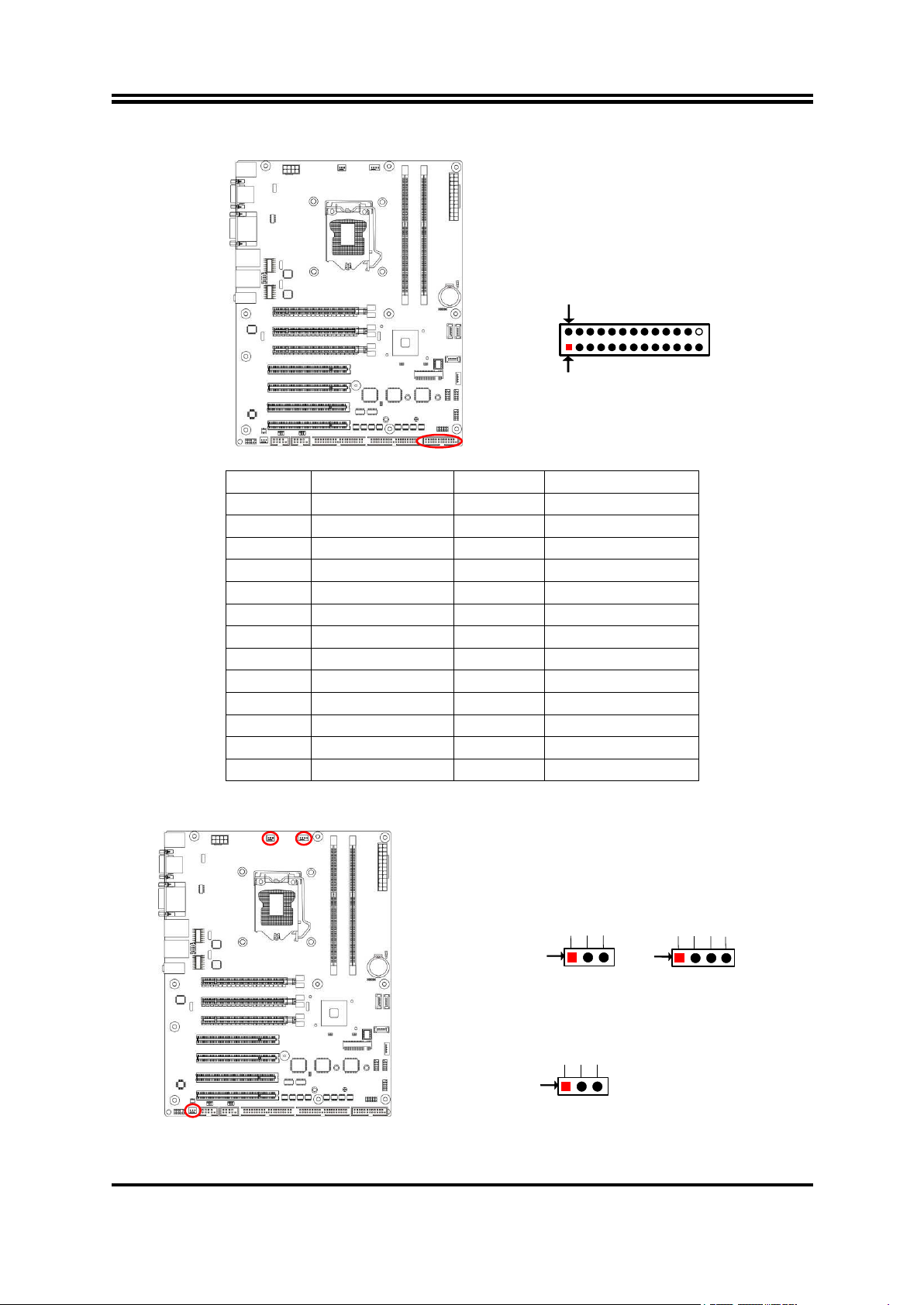
LPT (26-pin): Parallel Port Header
Pin 1
Pin 2
Pin NO.
Pin Definition
Pin NO.
Pin Definition
Pin 1
STB-
Pin 2
AFD-
Pin 3
PD0
Pin 4
ERR-
Pin 5
PD1
Pin 6
INIT-
Pin 7
PD2
Pin 8
SLIN-
Pin 9
PD3
Pin 10
GND
Pin 11
PD4
Pin 12
GND
Pin 13
PD5
Pin 14
GND
Pin 15
PD6
Pin 16
GND
Pin 17
PD7
Pin 18
GND
Pin 19
ACK-
Pin 20
GND
Pin 21
BUSY
Pin 22
GND
Pin 23
PE
Pin 24
GND
Pin 25
SLCT
Pin 26
No Key
SYSFAN1
Control
Fan Clock
+12V Fan Power
Pin1
GND
Pin1
GND
+12V Fan Power
Fan Clock
CPUFAN
Pin1
GND
+12V Fan Power
Fan Clock
SYSFAN2
SYSFAN1/SYSFAN2/CPUFAN1 (4-pin): FAN Headers
14
Page 19

Chapter 3
Introducing BIOS
Notice! The BIOS options in this manual are for reference only. Different
configurations may lead to difference in BIOS screen and BIOS
screens in manuals are usually the first BIOS version when the board
is released and may be different from your purchased motherboard.
Users are welcome to download the latest BIOS version form our
official website.
The BIOS is a program located on a Flash Memory on the motherboard. This program
is a bridge between motherboard and operating system. When you start the computer,
the BIOS program will gain control. The BIOS first operates an auto-diagnostic test
called POST (power on self test) for all the necessary hardware, it detects the entire
hardware device and configures the parameters of the hardware synchronization.
Only when these tasks are completed done it gives up control of the computer to
operating system (OS). Since the BIOS is the only channel for hardware and software
to communicate, it is the key factor for system stability, and in ensuring that your
system performance as its best.
3-1 Entering Setup
Power on the computer and by pressing <Del> immediately allows you to enter Setup.
If the message disappears before your respond and you still wish to enter Setup,
restart the system to try again by turning it OFF then ON or pressing the “RESET”
button on the system case. You may also restart by simultaneously pressing <Ctrl>,
<Alt> and <Delete> keys. If you do not press the keys at the correct time and the
system does not boot, an error message will be displayed and you will again be asked
to
Press <Del> to enter Setup
3-2 BIOS Menu Screen
The following diagram show a general BIOS menu screen:
15
Page 20
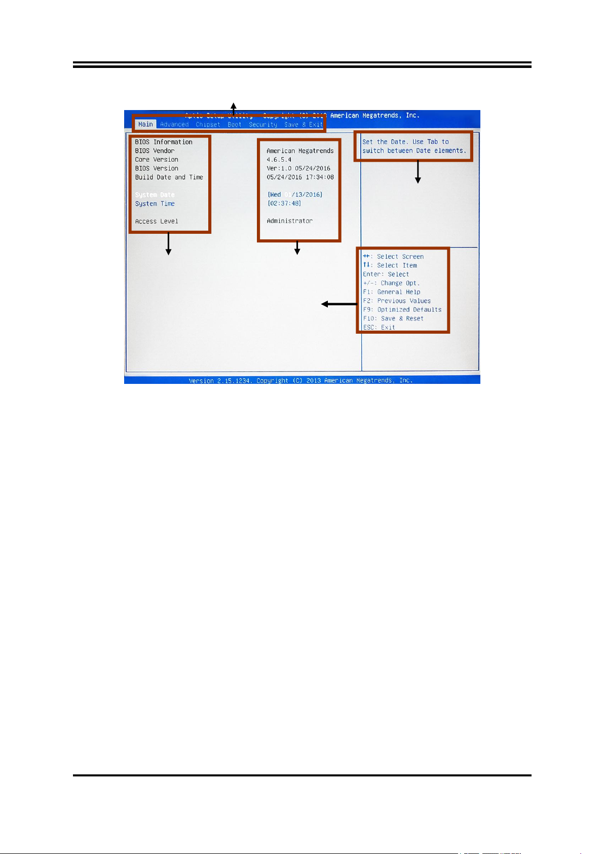
3-3 Function Keys
Press
(left, right) to select screen;
Press
(up, down) to choose, in the main menu, the option you want to confirm
Press <Enter> to select.
Press <+>/<–> keys when you want to modify the BIOS parameters for the active
[F1]: General help.
[F2]: Previous values.
[F9]: Optimized defaults.
[F10]: Save & Reset.
Press <Esc> to quit the BIOS Setup.
Menu Items
Current Setting Value
Function Keys
General Help Items
Menu Bar
In the above BIOS Setup main menu of, you can see several options. We will explain
these options step by step in the following pages of this chapter, but let us first see a
short description of the function keys you may use here:
or to modify.
option.
3-4 Getting Help
Main Menu
The on-line description of the highlighted setup function is displayed at the top right
corner the screen.
Status Page Setup Menu/Option Page Setup Menu
Press F1 to pop up a small help window that describes the appropriate keys to use
and the possible selections for the highlighted item. To exit the Help Window, press
<Esc>.
16
Page 21
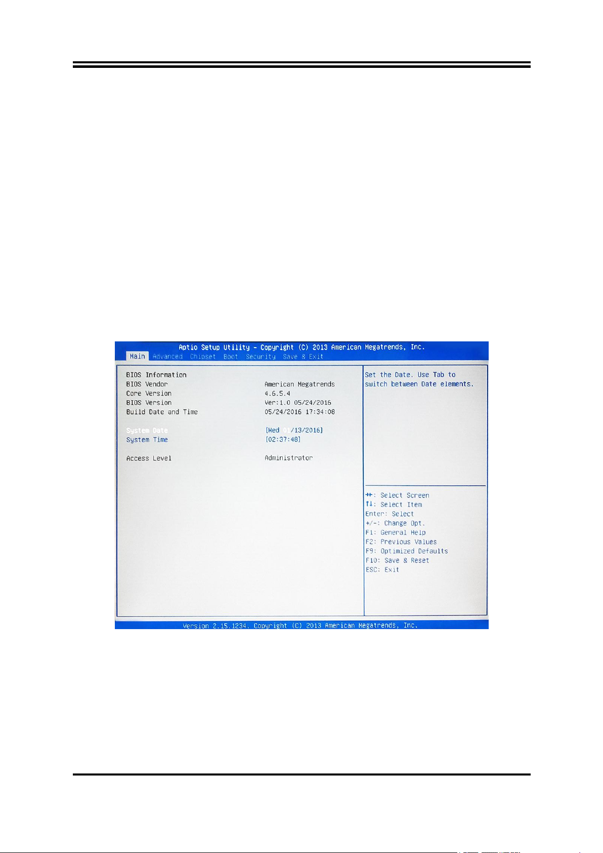
3-5 Menu Bars
Main
To change system basic configuration
Advanced
To change system advanced configuration
Chipset
To change chipset configuration
Boot
To change boot settings
Security
Password settings
Save & Exit
Save setting, loading and exit options.
There are menu bars on top of BIOS screen:
User can press the right or left arrow key on the keyboard to switch from menu bar.
The selected one is highlighted.
3-6 Main Menu
Main menu screen includes some basic system information. Highlight the item and
then use the <+> or <-> and numerical keyboard keys to select the value you want in
each item.
System Date
Set the date. Please use [Tab] to switch between data elements.
System Time
Set the time. Please use [Tab] to switch between time elements.
17
Page 22
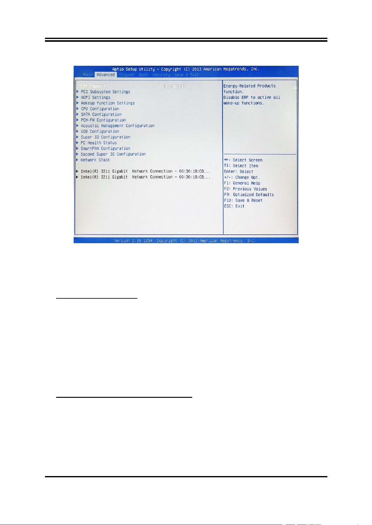
3-7 Advanced Menu
► PCI Subsystem Settings
▶ PCI Express Settings
ERP Function
The optional settings: [Disabled]; [Auto].
This item should be set as [Disabled] if you wish to have all active wake-up functions.
Press [Enter] to enter and make settings for the following sub-items:
PCI Common Settings:
PCI Latency Timer
Use this item to set value to be programmed into PCI latency timer register.
VGA Palette Snoop
Use this item to enable or disable VGA palette registers snooping.
PERR# Generation
Use this item to enable or disable PCI device to generate PERR#.
SERR# Generation
Use this item to enable or disable PCI device to generate SERR#.
Press [Enter] to make settings for the following sub-items:
PCI Express Device Register Settings:
Relaxed Ordering
Use this item to enable or disable PCI express device relaxed ordering.
Extended Tag
If set as [Enabled] it will allow device to use 8-bit tag field as a requester.
No Snoop
Use this item to enable or disable PCI Express device No Snoop option.
Maximum Payload
Use this item to set maximum payload of PCI Express device or allow system
18
Page 23

BIOS to select the value.
► ACPI Settings
► Wakeup Function Settings
► CPU Configuration
Maximum Read Request
Use this item to set maximum read request size of PCI Express device or allow
system BIOS to select the value.
Press [Enter] to make settings for the following sub-items:
ACPI Settings
ACPI Sleep State
Use this item to select the highest ACPI sleep state the system will enter when the
suspend button is pressed.
The optional settings are: [Suspend Disabled]; [S1 only (CPU Stop Clock)]; [S3
only (Suspend to RAM)].
Press [Enter] to make settings for the following sub-items:
Wake System with Fixed Time
Use this item to enable or disable system wake on alarm event. When set as
[Enabled], system will wake on the hour/min/sec specified.
PS2 KB/MS Wakeup
Use this item to enable or disable PS2 KB/MS wakeup from S3/S4/S5. This
function is only supported when ERP function is disabled.
PCI PME Wakeup
Use this item to enable or disable S1/S3/S4/S5 PCI PME Wakeup. This function is
only supported when ERP function is disabled.
USB S3/S4 Wakeup
Use this item to enable or disable USB S3/S4 wakeup. This function is only
supported when ERP function is disabled.
Press [Enter] to view current CPU configuration and make settings for the
following sub-items:
Hyper-Threading
The optional settings: [Disabled]; [Enabled].
[Enabled]: for Windows XP and Linux (OS optimized for Hyper-Threading
Technology).
[Disabled]: for other OS (OS optimized not for Hyper-Threading Technology).
*This item might not be available depending on configuration.
Active Processor Cores
Use this item to select number of cores to enable in each processor package.
Limit CPUID Maximum
The optional settings: [Disabled]; [Enabled].
This item should be set as [Disabled] for Windows XP.
Execute Disable Bit
The optional settings: [Disabled]; [Enabled].
Intel Virtualization Technology
The optional settings: [Enabled]; [Disabled].
When set as [Enabled], a VMM can utilize the additional hardware capabilities
provided by Vanderpool Technology.
EIST
19
Page 24

Use this item to enable or disable Intel SpeedStep.
► SATA Configuration
► PCH-FW Configuration
Turbo Mode
Use this item to enable or disable Turbo Mode.
*This item might not be available depending on configuration.
Energy Performance
Use this item to optimize between performance and power savings.
The optional settings are: [Performance]; [Balanced Performance]; [Balanced
Energy]; [Energy Efficient].
*This item might not be available depending on configuration.
CPU C Status
Use this item to enable or disable CPU C status.
The optional settings: [Disabled]; [Enabled].
When set as Enabled], the following sub-items shall appear:
CPU C6 Report
Use this item to enable or disable CPU C6 report to OS.
CPU C7 Report
Use this item to enable or disable CPU C7 report to OS.
The optional settings are: [Disabled]; [CPU C7]; [CPU C7s].
Press [Enter] to make settings for the following sub-items:
SATA Controller(s)
The optional settings: [Disabled]; [Enabled].
*When set as Enabled], user can make further settings in the following sub-items:
SATA Mode Selection
The optional settings are: [IDE]; [AHCI].
*When set as [IDE], user can make further settings in ‘IDE Legacy/Native Mode
Selection’.
IDE Legacy/Native Mode Selection
The optional settings are: [Native]; [Legacy].
*When set as [AHCI], user can make further settings in the following items:
Aggressive LPM Support
Use this item to enable PCH to aggressively enter link power state.
The optional settings: [Enabled]; [Disabled].
SATA Controller Speed
The item is for user to set the maximum speed the SATA controller can support.
The optional settings are: [Default]; [Gen1]; [Gen2]; [Gen3].
*When set as [AHCI], user can also make further settings for each available SATA
port(SATA1/2/5) or MSATA port:
Serial ATA Port 1/2/5/mSATA
Port 1/ Port 2/ Port 5mSATA
The optional settings: [Disabled]; [Enabled].
Use this item to enable or disable each SATA port.
SATA Device Type
The optional settings are: [Hard Disk Drive]; [Solid State Drive].
Press [Enter] to view ME information and make settings for ‘Firmware Update
20
Page 25

Configuration’.
► Firmware Update Configuration
► Acoustic Management Configuration
► USB Configuration
► Super I/O Configuration
Press [Enter] to make settings for ME FW Image RE-Flash.
ME FW Image RE-Flash
Use this item to enable or disable ME FW Image Re-Flash function.
The optional settings: [Disabled]; [Enabled].
* In the case that user needs to update ME firmware, user should set ‘ME FW
Image Re-Flash’ as [Enabled], save the settings and exit. The system will turn off
and reboot after 4 seconds. If the user goes to BIOS screen again will find this
item is set again as [Disabled], but user can still re-flash to update firmware next
time.
Press [Enter] to make settings for the following sub-items:
Press [Enter] to go to next screen to enable or disable ‘Automatic Acoustic
Management’.
Press [Enter] to make settings for the following sub-items:
Legacy USB Support
The optional settings are: [Enabled]; [Disabled]; [Auto].
[Enabled]: To enable legacy USB support.
[Disabled]: to keep USB devices available only for EFI specification,
[Auto]: To disable legacy support if no USB devices are connected.
XHCI Hand-off
This is a workaround for OSes without XHCI hand-off support. The XHCI
ownership change should be claimed by XHCI driver.
The optional settings are: Enabled]; [Disabled].
EHCI Hand-off
This is a workaround for OSes without EHCI hand-off support. The EHCI
ownership change should be claimed by EHCI driver.
The optional settings are: [Disabled]; [Enabled].
USB Mass Storage Driver Support
The optional settings are: [Disabled]; [Enabled].
USB Transfer time-out
Use this item to set the time-out value for control, bulk, and interrupt transfers.
The optional settings are: [1 sec]; [5 sec]; [10 sec]; [20 sec].
Device reset time-out
Use this item to set USB mass storage device start unit command time-out.
The optional settings are: [10 sec]; [20 sec]; [30 sec]; [40 sec].
Device power-up delay
Use this item to set maximum time the device will take before it properly reports
itself to the host controller. ‘Auto’ uses default value: for a root port it is 100 ms, for
a hub port the delay is taken from hub descriptor. The optional settings: [Auto];
[Manual].Select [Manual] you can set value for the following sub-item: Device
Power-up delay in seconds, the delay range in from 1 to 40 seconds, in one
second increments.
21
Page 26

Press [Enter] to make settings for the following sub-items:
► Serial Port 1 Configuration/ Serial Port 2 Configuration
► Serial Port 3 Configuration/ Serial Port 4 Configuration/ Serial Port 5
Super IO Configuration
Press [Enter] to make settings for the following items:
Serial Port
Use this item to enable or disable serial port (COM).
Change Settings
Use this item to select an optimal setting for super IO device.
Transmission Mode Select
The optional settings are: [RS422]; [RS232]; [RS485].
Mode Speed Select
The optional settings are: [RS232/RS422/RS485=250kbsp]; [RS232=1Mbsp,
RS422/RS485=10Mbsp].
Serial Port FIFO Mode
The optional settings are: [16-Byte FIFO]; [32-Byte FIFO]; [64-Byte FIFO];
[128-Byte FIFO].
Configuration/ Serial Port 6 Configuration
Press [Enter] to make settings for the following sub-items:
Serial Port
Use this item to enable or disable serial port (COM).
Change Settings
Use this item to select an optimal setting for super IO device.
Serial Port FIFO Mode
The optional settings are: [16-Byte FIFO]; [32-Byte FIFO]; [64-Byte FIFO];
[128-Byte FIFO].
PS2 KB/MS Connect
Use this item to set primary PS2 connect device.
The optional settings are: [Keyboard First]; [Mouse First]
WatchDog Timer
Press [Enter] to make settings for Watchdog Configuration:
Use this item to enable or disable WatchDog Timer Control.
The optional settings: [Disabled]; [Enabled].
*When set as [Enabled], the following sub-items shall appear:
WatchDog Timer Value
User can set a value in the range of 4 to 255.
WatchDog Timer Unit
The optional settings are: [Sec.];[Min.].
ATX Power Emulate AT Power
This item support Emulate AT power function, MB power On/Off control by power
supply. Use needs to select ‘AT or ATX Mode’ on MB jumper at first (refer to Page
6 , AT_MODE jumper for ATX Mode & AT Mode Select).
Case Open Detect
This item controls detect case open function.
The optional settings: [Disabled]; [Enabled].
When set as [Enabled], system can detect case has already open or not and show
message in POST.
22
Page 27

► PC Health Status
Press [Enter] to view current hardware health status or make further settings in
► SmartFan Configuration
► Second Super IO Configuration
► Serial Port 7 Configuration/ Serial Port 8 Configuration/ Serial Port 9
► Parallel Port Configuration
Network Stack
‘Shutdown Temperature’.
Shutdown Temperature
Use this item to select system shutdown temperature.
The optional settings are: [Disabled]; [70oC/156oF]; [75oC/164oF]; [80oC/172oF];
[85oC/180oF]; [90oC/188oF].
Press [Enter] to make settings for SmartFan Configuration:
CPUFAN / SYSFAN1/ SYSFAN2 Smart Mode
When set as [Enabled], the following sub-items shall appear:
CPUFAN / SYSFAN1/ SYSFAN2 Full-Speed Temperature
Use this item to set CPUFAN/SYSFAN1/SYSFAN2 full speed temperature. Fan
will run at full speed when above the preset temperature.
CPUFAN / SYSFAN1/ SYSFAN2 Full-Speed Duty
Use this item to set CPUFAN/SYSFAN1/SYSFAN2 full speed duty. Fan will run at
full speed when above the pre-set duty.
CPUFAN / SYSFAN1/ SYSFAN2 Idle-Speed Temperature
Use this item to set CPUFAN/SYSFAN1/SYSFAN2 idle speed temperature. Fan
will run at idle speed when below the pre-set temperature.
CPUFAN / SYSFAN1/ SYSFAN2 Idle-Speed Duty
Use this item to set CPUFAN/SYSFAN1/SYSFAN2 idle speed duty. Fan will run at
idle speed when below the pre-set duty.
Second Super IO Configuration
Configuration/ Serial Port 10 Configuration
Serial Port
Use this item to enable or disable serial port (COM).
Change Settings
Use this item to select an optimal setting for super IO device.
Parallel Port
Use this item to enable or disable parallel port (LPT).
Change Settings
Use this item to select an optimal setting for super IO device.
Device Mode
Use this item to change the printer port mode.
The optional settings are: [STD Printer Mode]; [SPP Mode]; [EPP-1.9 and SPP
Mode]; [EPP-1.7 and SPP Mode]; [ECP Mode]; [ECP and EPP 1.9 Mode]; [ECP
and EPP 1.7 Mode].
Press [Enter] to go to ‘Network Stack’ screen to make further settings.
Network Stack
23
Page 28
The optional settings are: [Enabled]; [Disabled].
Intel(R) I211 Gigabit Network Connection -XX:XX:XX:XX:XX:XX/ Intel(R)
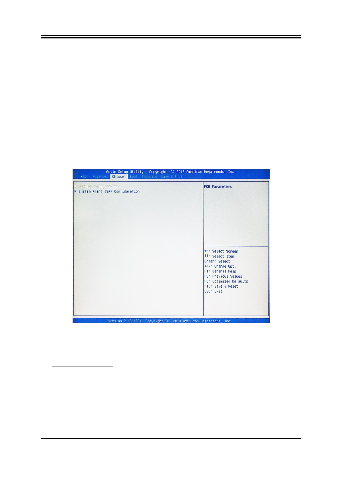
► PCH-IO Configuration
► USB Configuration
When set as [Enabled], the following sub-items shall appear:
Ipv4 PXE Support
The optional settings are: [Disabled]; [Enabled].
Use this item to enable Ipv4 PXE Boot Support. When set as [Disabled], Ipv4 boot
optional will not be created.
Ipv6 PXE Support
The optional settings are: [Disabled]; [Enabled].
Use this item to enable Ipv6 PXE Boot Support. When set as [Disabled], Ipv6 boot
optional will not be created.
I211 Gigabit Network Connection -XX:XX:XX:XX:XX:XX
This item gives Intel gigabit ethernet controller basic driver information.
3-8 Chipset Menu
Press [Enter] to make settings for the following sub-items:
Press [Enter] to further setting USB device configuration.
USB Configuration
XHCI Mode
Use this item to select mode of operation for XHCI controller.
The optional settings are: [Smart Auto]; [Auto]; [Enabled]; [Disabled]; [Manual].
*When set as [Disabled], the following sub-items shall appear:
EHCI1/EHCI2
Use this item to control the USB EHCI (USB 2.0) functions.
One EHCI controller must always be enabled.
*When set as [Manual], the following sub-items shall appear:
24
Page 29

Route USB 2.0 pins to which HC?
► System Agent (SA) Configuration
► Graphics Configuration
The optional settings are: [Route Per-Pin]; [Route all Pins to EHCI]; [Route all Pins
to XHCI].
Enable USB 3.0 pins
The optional settings are: [Select Per-Pin]; [Disable all Pins]; [Enable all Pins].
Azalia
Use this item to control detection of the Azalia device.
The optional settings are: [Disabled]; [Enabled];[Auto].
[Disabled]: Azalia will be unconditionally disabled;
[Enabled]: Azalia will be unconditionally enabled.
[Auto]: Azalia will be enabled if present, disable otherwise.
Onboard LAN1 Controller/ Onboard LAN2 Device
Use this item to enable or disable onboard LAN controller.
SLP_S4 Assertion Width
Use this item to select a minimum assertion width of the SLP_S4# signal to ensure
that the DRAMs has been safely power-cycled.
The optional settings are: [1-2 Seconds]; [2-3 Seconds]; [3-4 Seconds]; [4-5
Seconds].
Restore AC Power Loss
Use this item to select AC power state when power is re-applied after a power
failure.
The optional settings are: [Power Off]; [Power On]; [Last State].
Press [Enter] to make settings for the following sub-items:
VT-D
The optional settings are: [Enabled]; [Disabled].
*This item might not be available depending on configuration.
Azalia Internal HDMI Codec
Use this item to enable or disable DP/HDMI/DVI port audio device.
The optional settings are: [Enabled]; [Disabled].
Press [Enter] to make further settings for Graphics Configuration.
Graphics Configuration
Primary IGFX Boot Display
Use this item to select the video device which will be activated during POST. This
has no effect if external graphics present. Secondary boot display selection will
appear based on your selection. VGA modes will be supported only on primary
display.
The optional settings are: [VBIOS Default]; [VGA1]; [VGA2]; [HDMI]; [DVI].
*When set as [CRT]; [HDMI]; [DVI] or [Display Port], the following sub-item shall
appear:
Secondary IGFX Boot Display
The optional settings are: [Disabled]; [VGA1]; [VGA2]; [HDMI]; [DVI].
Primary Display
Use this item to select which of IGFX/PEG/PCI graphics device should be primary
display.
The optional settings are: [Auto]; [IGFX]; [PEG]; [PCI].
25
Page 30

Internal Graphics
► PEG Slot Configuration
► Memory Configuration
The optional settings are: [Auto]; [Disabled]; [Enabled].
Aperture Size
The optional settings are: [128MB]; [256MB]; [512MB].
DVMT Pre-Allocated
Use this item to select DVMT 5.0 pre-allocated (fixed) graphics memory size used
by the internal graphics device.
The optional settings are: [32M]; [64M]; [128M]; [256M]; [512M]; [1024M].
DVMT Total Gfx Mem
Use this item to select DVMT 5.0 total graphics memory size used by the internal
graphics device.
The optional settings are: [128M]; [256M]; [MAX].
Press [Enter] to make settings for the following sub-items:
PEG Slot Configuration
PEG-Gen X
The optional settings are: [Auto]; [Gen1]; [Gen2]; [Gen3].
Enable PEG
The optional settings are: [Auto]; [Disabled]; [Enabled].
Detect Non-Compliance Device
Use this item to detect non-compliance PCI Express device in PEG.
The optional settings are: [Disabled]; [Enabled].
Program PCIe ASPM after OpROM
The optional settings are: [Enabled]; [Disabled].
[Enabled]: PCIe ASPM will be programmed after OpROM.
[Disabled]: PCIe ASPM will be programmed before OpROM.
PEG De-emphasis Control
Use this item to configure the De-emphasis control on PEG.
The optional settings are: [-6 dB]; [-3.5 dB].
PEG ASPM
Use this item to control ASPM support for the PEG device. This has no effect if
PEG is not the currently active device.
The optional settings are: [Disabled]; [Auto]; [ASPM L0s]; [ASPM L1]; [ASPM
L0sL1].
Press [Enter] to view basic information for working memory or make settings for
the following sub-items:
Memory Frequency Limiter
Use this item to set maximum memory frequency selection in Mhz.
The optional settings are: [Auto]; [1067]; [1333]; [1600]; [1867].
26
Page 31
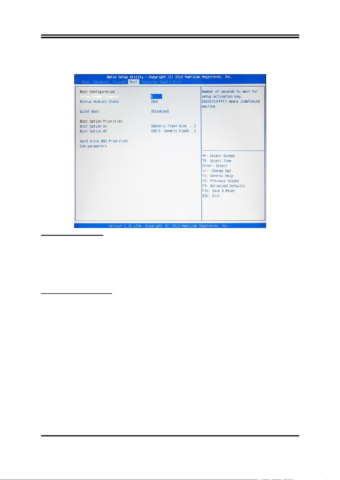
3-9 Boot Menu
► CSM parameters
Boot Configuration
Setup Prompt Timeout
Use this item to set number of seconds to wait for setup activation key.
Bootup Numlock State
Use this item to select keyboard numlock state. The optional settings are: [On]; [Off].
Quiet Boot
The optional settings are: [Disabled]; [Enabled].
Boot Option Priorities
Press [Enter] to make settings for the following sub-items:
Boot option filter
This option controls what device system can boot to.
The optional settings are: [UEFI and Legacy]; [Legacy only]; [UEFI only].
Launch PXE OpROM policy
This option controls the execution of UEFI and Legacy PXE OpROM.
The optional settings are: [Do not launch]; [UEFI only]; [Legacy only].
Launch Storage OpROM policy
This option controls the execution of UEFI and Legacy Storage OpROM.
The optional settings are: [Do not launch]; [UEFI only]; [Legacy only].
Launch Video OpROM policy
This option controls the execution of UEFI and Legacy Video OpROM.
The optional settings are: [Do not launch]; [UEFI only]; [Legacy only].
Other PCI device ROM priority
This item is for PCI devices other than Network, Mass storage or video defines
which OpROM to launch.
27
Page 32
The optional settings are: [UEFI OpROM]; [Legacy OpROM].
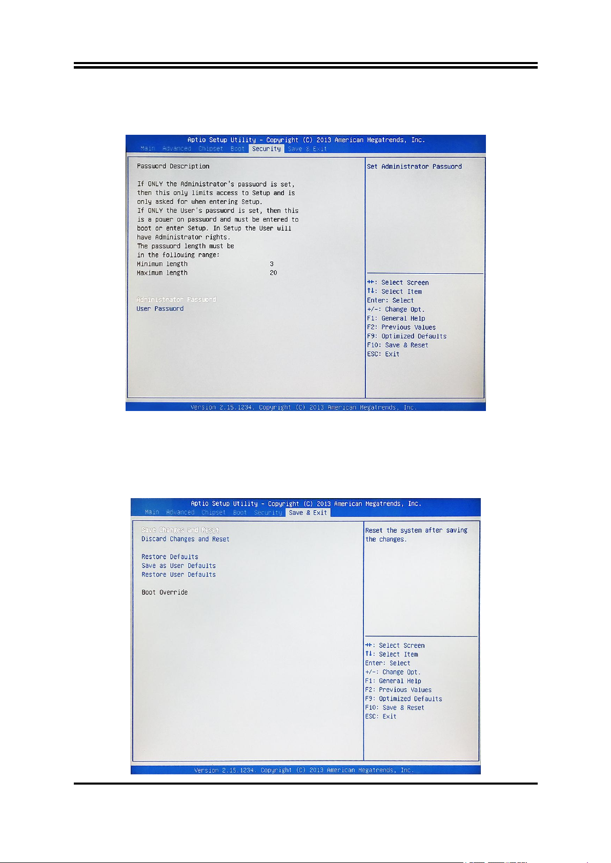
3-10 Security Menu
Administrator Password
This item allows user to set administrator password.
User Password
This item allows user to set user password.
3-11 Save & Exit Menu
28
Page 33

Save Changes and Reset
This item allows user to reset the system after saving the changes.
Discard Changes and Reset
This item allows user to reset the system without saving any changes.
Restore Defaults
Use this item to restore /load default values for all the setup options.
Save as User Defaults
Use this item to save the changes done so far as user defaults.
Restore User Defaults
Use this item to restore defaults to all the setup options.
29
 Loading...