

Page 1
gger
D A T A L O G G I N G
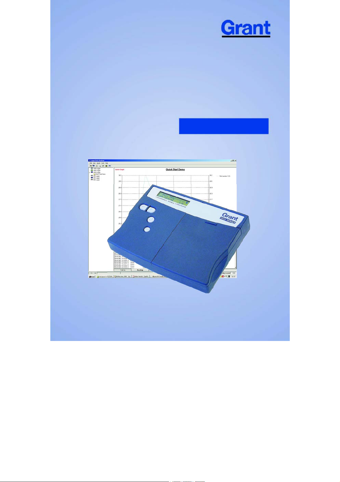
Squirrel Data Lo
2020/2040 SERIES
Quick Start
Page 2
N
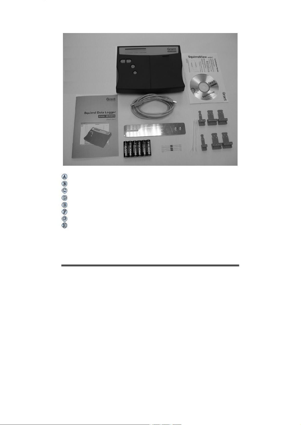
1. Hardware Checklist
2020/2040 Logger x 1
CD containing software x 1 (SQA100)
2020/2040 SERIES Quick Start manual (this booklet) x 1
USB Cable x 1 (LC77)
Mounting bracket/stand for logger x 1 (WB6)
Batteries, 6 x AA
Current shunt resistors, 10R x 4 (CS202)
Connectors: 6 way x 4 (18097), 4 way x 1 (13975), 3 way x 1
(14174), with cable ties
ote: 2040 Logger is supplied with an extra 4 x 6 way
connectors as above (18097).
Version 2 - July 2004
Page 2
18108
Page 3
Contents
1 .2 Hardware Checklist.
2 .4 General Information.
3 .5 Menu and Navigation.
4 Getting Started. .7
5 .11 Connections.
6 .13 Specifications.
18108
After reading this Quick Start,
please refer to SquirrelView
Help for further details on your
logger and how to use it with
SquirrelView.
Version 2 -July 2004
Page 3
Page 4

N
2. General Information
2
Installing the batteries
The 2020/2040 uses six AA size alkaline batteries located under the removable cover
shown below. To insert new or change the existing batteries:
* It is recommended that all replacement batteries are of the same manufacturer, type and
condition.
The 2020/2040 can be used in either the Battery mode or Externally powered mode.
1. Open the battery cover by pushing down and sliding as shown.
2. Insert six AA* batteries, ensuring the correct polarity.
3. Refit the battery cover.
Battery mode
When logging in this mode please ensure that the batteries in the unit have
This can be checked via the sufficient capacity to complete the logging task.
battery indicator located in the top right of the display.
HIGH LOW
Externally powered mode
The logger may be powered from an external source (10-18V DC)
CAPACITY CAPACITY
Page 4
ote: To ensure data protection in the case of an unexpected power loss,
please ensure that batteries are fitted whilst the unit is operational.
18108 Version 2 - July 2004
Page 5
3. Menu and Navigation
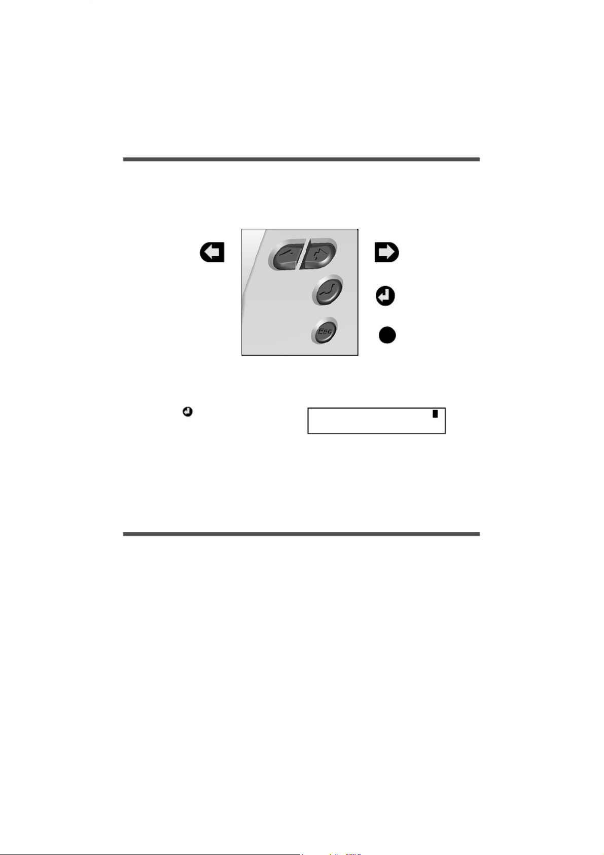
3.1 Control panel
The illustration below shows the navigation controls in more detail.
LEFT
NAVIGATION
KEY
To use the 2020/2040 control panel
press , the opening display will be
shown (see right). The display timeout is
preset to 10 seconds, however this can
be changed by selecting the
Configuration tab within the Logger
Setup window of SquirrelView.
Esc
--Main Menu----1/6Log Control
RIGHT
NAVIGATION
KEY
ENTER/
CONFIRM &
POWER ON KEY
ESCAPE KEY
(reverts to previous
menu)
18108 Version 2 - July 2004
Page 5
Page 6

3.2 Control panel menu
Detailed below is a basic explanation of the top menu structure. For more information on
the whole menu structure please refer to the Help/Help Content - Loggers within
SquirrelView.
3.3.1
3.3.2
3.3.3
3.3.4
Log Control
In this menu you can Arm (activate) or
Disarm (deactivate) the logger.
Meter
Here you can view each channel in Real
Time mode, data will be updated every
1-2 seconds. You can also scroll or auto
scroll through the channels.
Status
The Status menu gives you access to
information relating to the logger such as
memory and power supply voltage. You
can also override the alarm outputs
in here.
Setup
This contains menus for setting up
Language, Time & Date and the
opportunity to store and recall Setups.
3.3.6
Version 2 - July 2004
Page 6
Data Files
This menu allows you to copy data files
an external memory card (if fitted)
to
and Data Files 5/6 delete the data files
held within the logger’s memory.
Tools
The tools menu contains maintenance
type functions such as querying the
software version of the logger and
performing a self test and resetting
the Logger.
18108
Page 7
A
r
4. Getting started
4.1
4.2
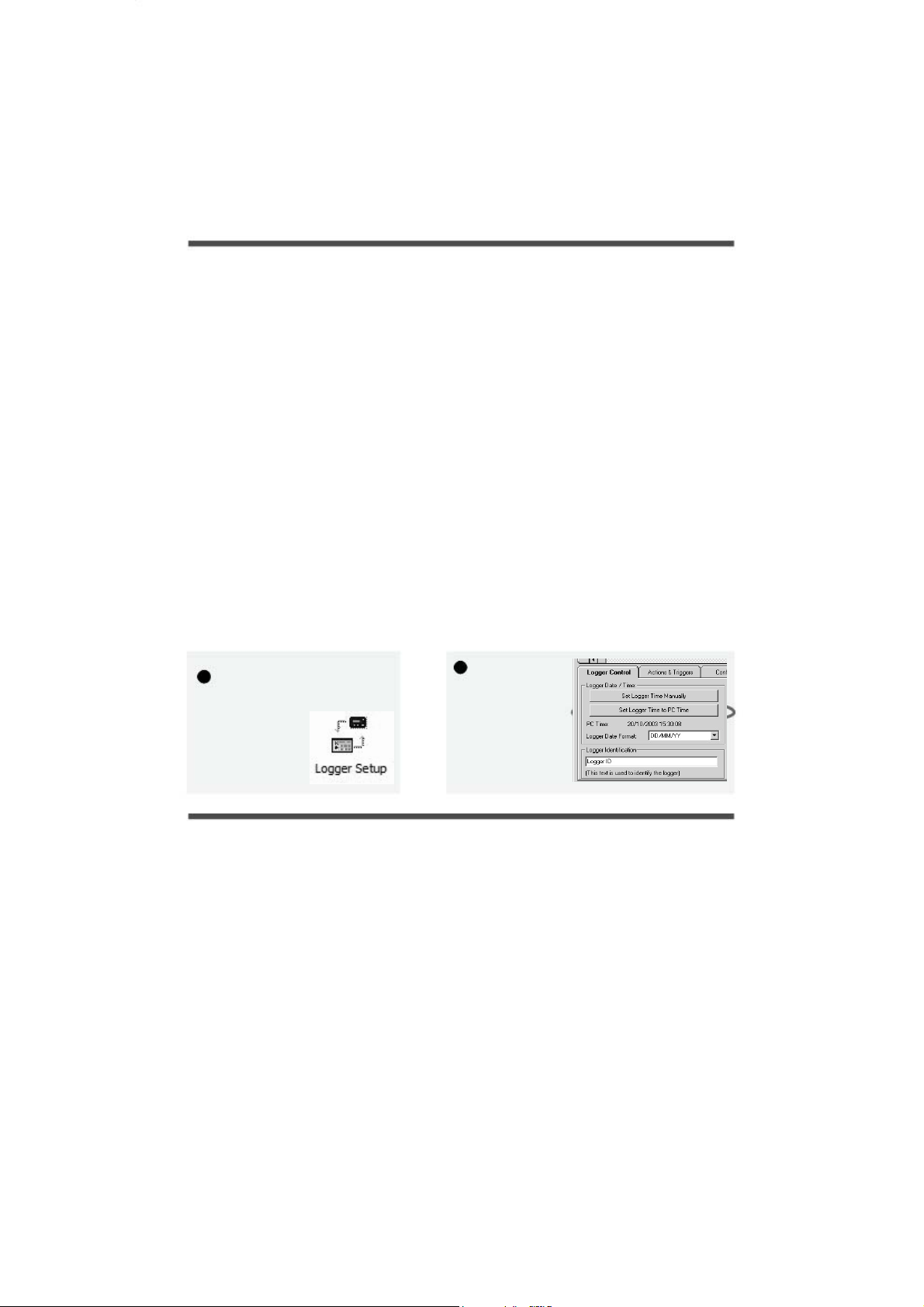
4.3 Startup SquirrelView and select Logger Type
4.4
Synchronise clocks:
Quick Start example
fter installing SquirrelView an example setfile will be installed within the SquirrelView
installation directory. The example file will log the internal temperature of the logger. In
order to familiarise yourself with the logger the novice user may find this example Setup
useful.
Installing SquirrelView software
Install the software by following the instructions on the SquirrelView Installation Guide.
Connect the 2020/2040 to the PC via either USB or Serial connections. If you are using USB
the PC will request the USB drivers (it is assumed that SquirrelView is installed into the default
directory, if this is not the case then modify the path accordingly), select C:\Program
Files\SquirrelView\USB\ then click OK to complete the installation. Please ignore the
Hardware Installation warning that refers to Windows Logo testing.
Click on the shortcut icon on your desktop to launch SquirrelView or select it from your start
menu - Program group menu within Windows. When the SquirrelView Assistant has opened,
ensure the correct logger type and communication method is selected. This can be viewed in
the top right corner of the screen, if you need to make any changes select Logger Selection from
the toolbar or run the Communication Wizard.
Synchronise Logger & PC
It is advisabl to start by synchronising the Logger clock with the PC clock. See step 1 e
and 2 below:
From
1
SquirrelView Assistant
click on Logge
Setup.
2
From the Logger
Setup screen select
the Logger Control
tab.
Click on Set Logger
Time to PC Time,
click OK on the
confirmation screen.
18108 Version 2 - July 2004
Page 7
Page 8
A
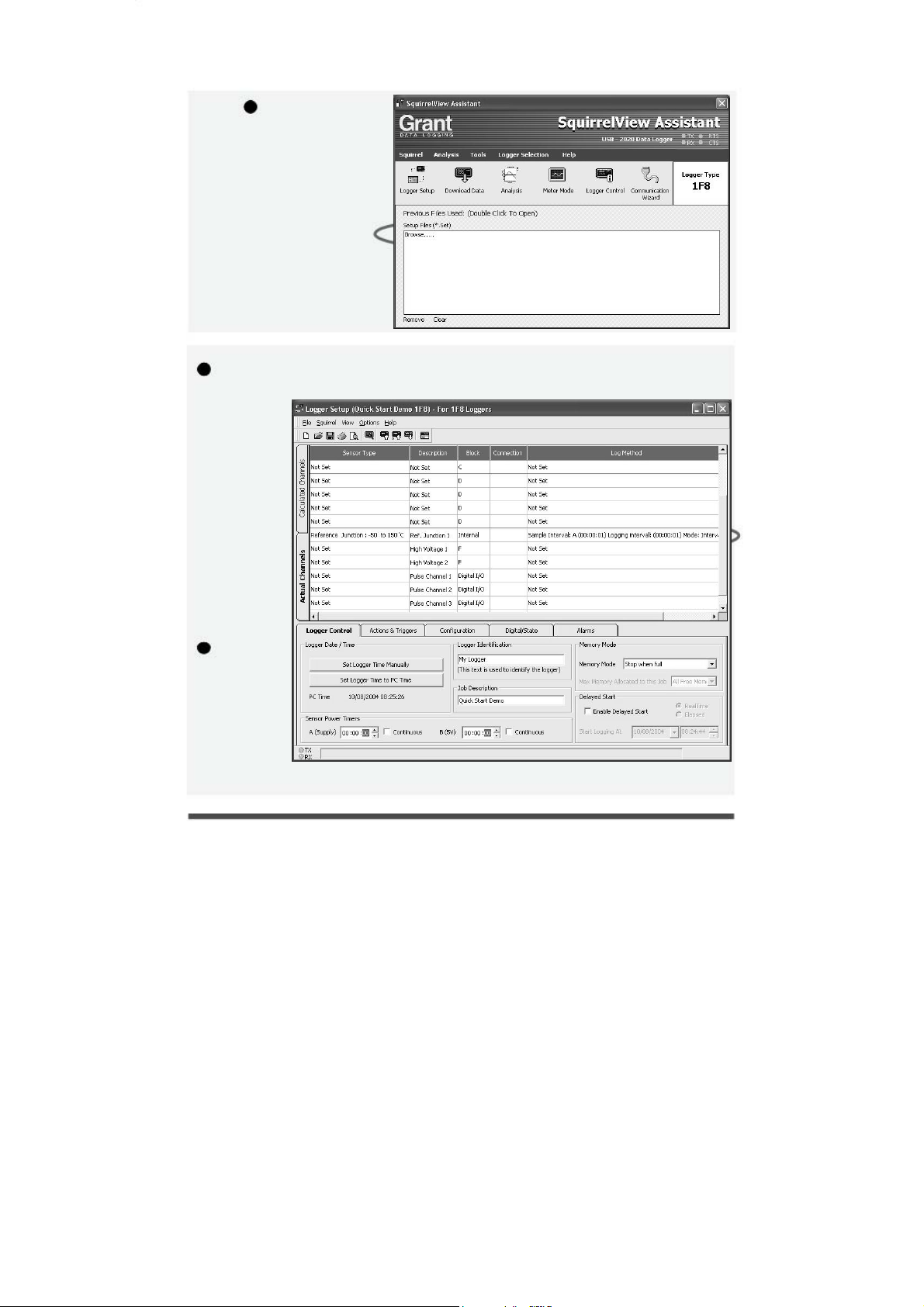
4.5 Running Quick Start Demo
1
In the
SquirrelView
ssistant,
double click on
Browse. .or select
File - Open from
Logger setup to
open a setfile
Or select the
quick start demo
file appropriate to
your logger type.
2
The Logger
Setup screen
is now
visible, from
here you will
be able to set
up your
logging
requirements.
Within the Actual
Channels tab
scroll down
e Sensor
th
T pe column
y
to Ref.J1.
This will be
the input you
will be
reading in this
example.
3
The Job
Description
can be used to
describe your
setup.
1
2
3
Version 2 - July 2004
Page 8
18108
Page 9
r
r
r
4
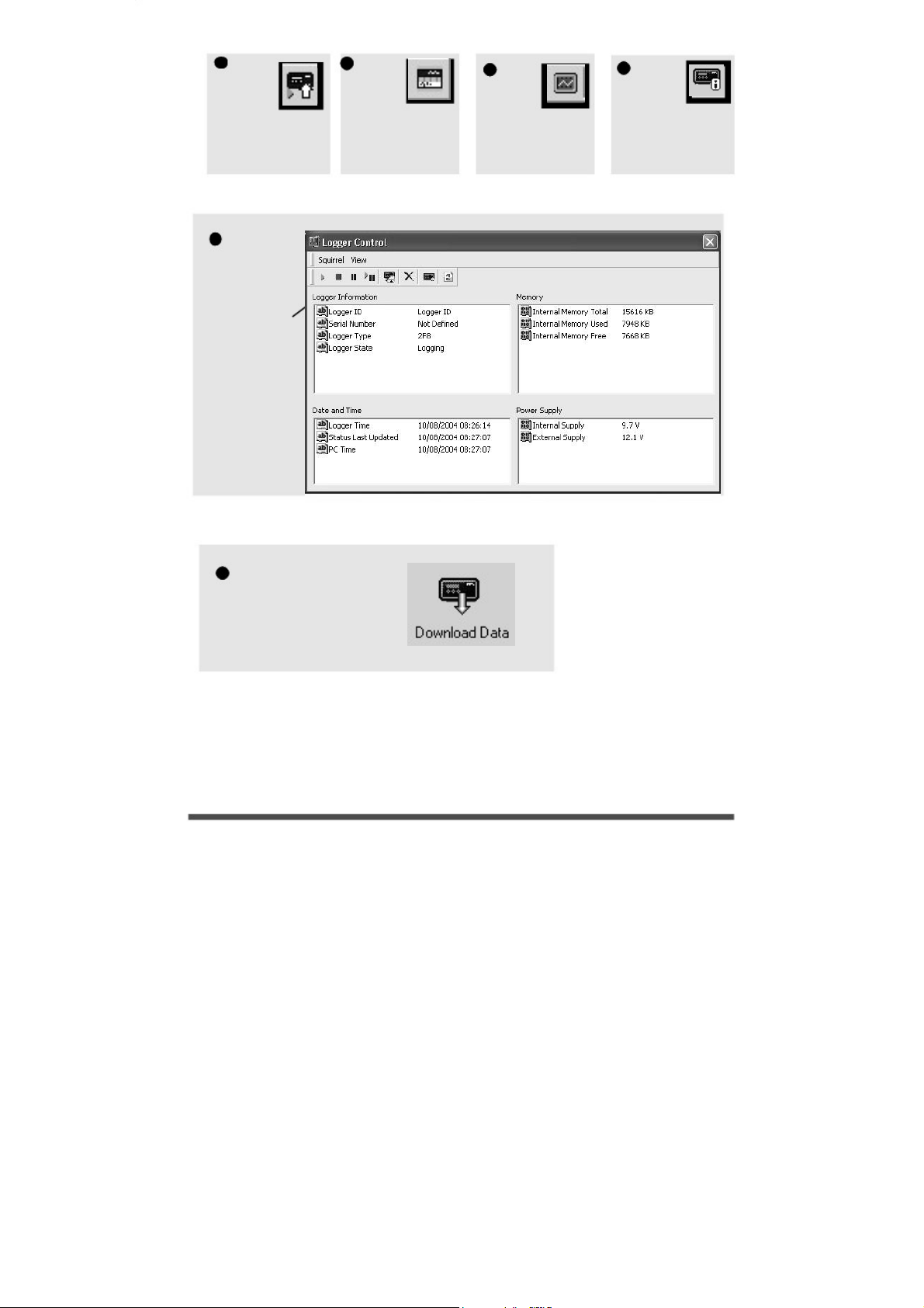
Click
to send
setup to
logge
and start
logging. Let the unit
log for a few
minutes.
8
In the Logger
Control
window you
can view
relevant
information on
the state of the
logger. To stop
logging click
.
n the stop
o
button.
5
Click fo
SquirrelView
Assistant.
6
If you
wish to
meter
the input
in Real
Time click this
icon.
7
To
pause o
stop the
logging
process click the
Logger Control
icon.
9 To Download the logger
click on the Download
Data icon from the
SquirrelView Assistant.
18108
Version 2 - July 2004
Page 9
Page 10
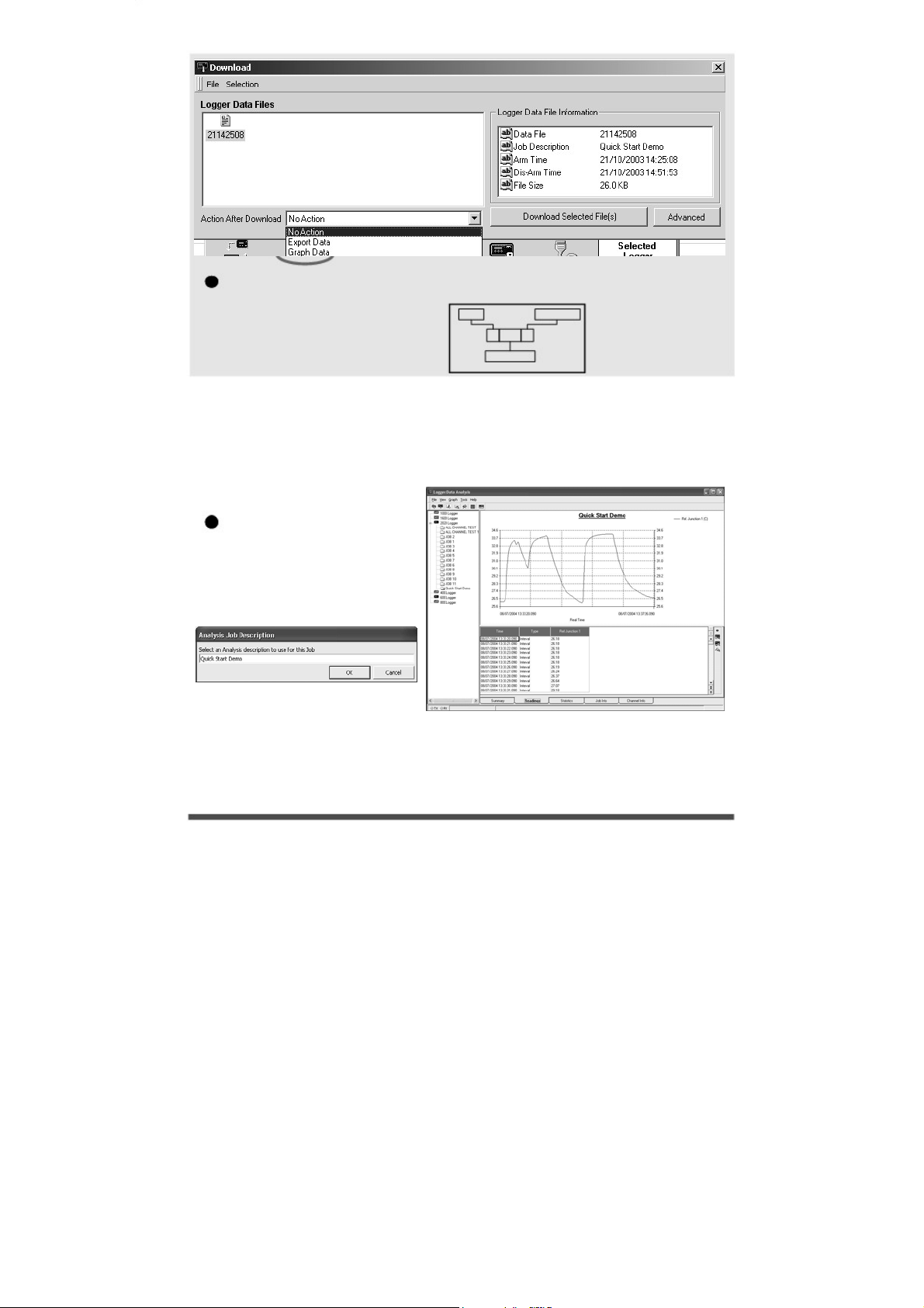
10 In this screen you can now download the Data file and invoke the Export Wizard
or download the Datafile via Analysis*
The datafile is given a unique name
(e.g. 28162735.D20). An
explanation of the file name is
shown on the right.
DATE
28162735 .D20
TIME(24HR)
In this example you will download and view the Data in the Analysis* window. Start by
selecting the Data file and Graph Data action, then click Download Selected File(s). You
will be prompted to save the Data file. Once you have done this then the data will be
converted for viewing.
*Available with SquirrelView Plus only.
SECONDS
11 Once the decoding has
11
taken place the Analysis Job
Description window will be
presented, click OK to view
your data.
Page 10
18108 Version 2 - July 2004
Page 11
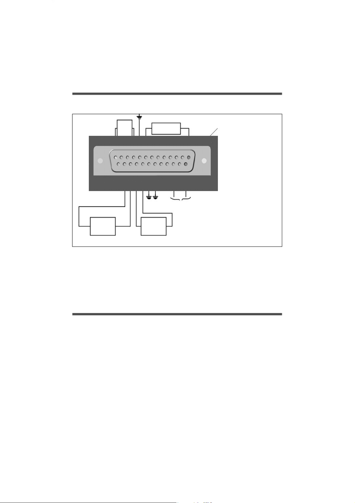
A
5. Connections
I/O SOCKET Wiring information
SLOW PULSE
I/P 1-2
ALARM
O/P
EVENT/STATE
I/P 1-8
FAST PULSE
I/P 1-2
ux. Output
Max 500mA
PIN 1
18108
Version 2 - July 2004
Page 11
Page 12
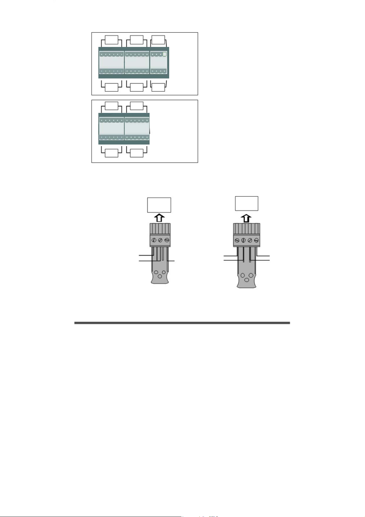
A
N
A
Analogue Inputs (I/P)
BLOCK
A
1 1 2 2 4 4 5 5 1 1 2 2 4 4 5
BLOCK
B
BLOCK
G
1 1 2 2 4 4 5 5 1 1 2 2 45
BLOCK
H
BLO K C
C
BLO K C
D
BLO K C
J
BLO K C
K
45
5
BLOCK
E
13
12 4
BLOCK
F
Rear view of
NALOGUE
connectors
Rear view of
NALOGUE
connectors
FOR ANALOGUE INPUT CONNECTIONS
REFER TO
SquirrelView/
Logger Setup/Sensor Type.
BLOCK
E
OTE: Blocks G TO K are only
available on 2040 loggers.
BLOCK
F
UNREGULATED LOGGER
SUPPLY OUTPUT
REGULATED 5V OUTPUT
Version 2 - July 2004
Page 12
NEGATIVE
SENSOR POWER SUPPLIES
V1(+)
V1(-)
HIGH VOLTAGE INPUT
V2(-)
V2(+)
18108
Page 13

N
6. Specifications
ANALOGUE INPUTS
ANALOGUE-DIGITAL CONVERSIONANALOGUE-DIGITAL CONVERSION
ALARM OUTPUTS.
SENSOR POWER SUPPLY.
TIME AND DATE.
SCALING DATA.
MEMORY.
RESOLUTION.
PROGRAMMING/LOGGER SET-UP.
COMMUNICATION.
Basic accuracy: (5-45°C) .
Common mode rej ction: .Common mode rej ction: .e
Input impe ance: .
Input impe ance: . d
Linearity: .
Linearity: .
Series mode line rejection:.Series mode line rejection:.
Type: .Type: .
Resolution: .Resolution: .
Sampling rate: . Sampling rate: .
e
d
External options: .
.± (0.05% readings + 0.025% range)
.Up to 20.Up to 20/100 readings per second
ote: 100Hz Mode not available on 1F8 models
.4 x open drain FET (18V 0.1A Max)
.Regulated 5 VDC (50mA) or supply voltage (100mA)
.Displays readings in preferred engineering units
.Internal: 16Mb (Up to 1,800,000 readings)
External: Up to 64Mb removable MMC
.SquirrelView or SquirrelView Plus software
+ 0.025% range)
.100dB .100dB
.> 1MOHM .> 1MOHM
.0.015%.0.015%
.50/60Hz 100dB .50/60Hz 100dB
.Sigma-Delta .Sigma-Delta
.24bit .24bit
.In built clock in 3 formats
.Up to 6 significant digits
.USB 1.1 and 2.0 / RS232
.GSM and Ethernet
18108 Version 2 - July 2004
Page 13
Page 14
N
POWER SUPPLY
* Maximum operating temperature for AA alkaline batteries is 50°C
POWER CONSUMPTION @ 9V
DIMENSIONS AND WEIGHT
MEMORY MODES (internal only).
DISPLAY AND KEYPAD
OPERATING ENVIRONMENT . .-30°C to +65°C
Internal:.
External: .
Sleep mode: .
Logging: .
2020 Logger
Dimensions: .
Weight: .
Enclosure material: .
2040 Logger
Dimensions: .
Weight: .
Enclosure material:.
2 line x 20 character LCD display
.10-18VDC Reverse polarity and over-voltage protected
.6* x AA Alkaline batteries
.<600µA
.40 - 80mA
.W235 x D175 x H55 mm
.Approx 1.2kgs
. ABS
.W235 x D175 x H92 mm
.Approx1.5kgs
.ABS
.Stop when full or overwrite
Corporation in the United States and other countries.
Due to our policy of continuous improvements, specifications may
change without prior notice.
Grant believe that all information declared is correct at the time of issue.
o liability is accepted for errors and omissions.
Version 2 - July 2004
Page 14
Windows is a registered trademark of Microsoft
18108
Page 15
A
Declaration of Conformity
Manufacturer:
Equipment Name/Type Number:
Description of Equipment:
Directives:
Including Accessories:
This product complies with the requirements of the above Directive(s)
Applied Standards:
Harmonized Standards:
USA
This device complies with Part 15 of the FCC rules. Operation is subject to the
following two conditions: (1) this device may not cause harmful interference, and
(2) this device must accept any interference received, including interference that
may cause undesired operation.
AUSTRALIA & NEW ZEALAND
NC
006 134 863
GRANT INSTRUMENTS (CAMBRIDGE) LTD,
Shepreth,
Cambridgeshire
SG8 6GB
2020/2040
Squirrel 2020/2040 Data Logger
EMC Directive 89/336/EEC
MPU 12V Universal power supply
LC71
LC77
EN 61326-1:1998 (+A1/A2)
This product complies with the requirements of the
European EMC standards indicated above which
meet the requirements for C-Tick marking.
RS232 serial lead
USB lead
Electrical Equipment for measurement,
control and laboratory use EMC requirements
18108 Version 2 - July 2004
Page 15
Page 16

Grant Instruments
(Cambridge) Ltd
Shepreth,
Cambridgeshire
SG8 6GB
Tel: +44 (0)1763 260811
www.grant.co.uk
Fax: +44 (0)1763 262410
Printed in England - Squirrel/2020/2040-18108/UK
Page 17

 Loading...