


Densitometer
DEN-1B
-bio
Operating instructions


Contents
Page 3
DEN-1B
Operating instructions
Version 1.01 - May 2012
1 Safety ........................................................................................4
2 General Information ................................................................6
3 Getting started .........................................................................8
4 Operation of DEN-1B ...............................................................10
5 Maintenance .............................................................................12
6 Specifications...........................................................................13
7 Guarantee and service ............................................................14

1. Safety
The following symbol means:
Caution: Read this operating instructions fully before use and pay particular attention
to sections containing this symbol.
GENERAL SAFETY
Operation of the unit must be carried out according to the given operating instructions.
Connect only to a power supply with a voltage corresponding to that on the serial number label.
Only use the external power supply unit provided with this product.
Ensure that the power switch and external power supply connector are easily accessible during
use.
Before moving, disconnect from the mains.
To turn off the unit, disconnect the external power supply from the mains outlet.
If liquid is spilt inside the unit, disconnect it from the external power supply and have it checked
by a competent person.
Batteries
Use alkaline (preferred) or rechargeable AA type batteries.
ATTENTION DANGER, risk of explosion and burns:
·The batteries must be inserted correctly with respect to polarity by following the diagram in
the battery case.
·If one battery is reversed (two + poles or two - poles in contact with each other), a chemical
reaction is produced in minutes that releases explosive gasses and extremely corrosive
liquid.
The unit should be saved from shocks and falling.
After transport or storage dry out the unit (2-3 hrs) before connecting it to the supply voltage.
Before using any cleaning or decontamination method except those recommended by the
manufacturer, user should check with the manufacturer that the proposed method will not
damage the equipment.
Do not make modifications in design of the unit.
ELECTRICAL SAFETY
Page 4
DEN-1B
Operating instructions
Version 1.01 - June 2012

·In case of doubt, turn off the unit immediately and check the polarity.
·Protect your eyes in case leakage has already occurred. Cover the battery case with a rag
before opening it to avoid contact with any discharge.
·In case of contact with liquid from the batteries, rinse affected area immediately with clear
water and get immediate medical attention.
·Do not mix brands of batteries.
·Do not mix new and used batteries.
·Remove the batteries from the unit for prolonged storage.
·Do not recharge alkaline batteries.
·Do not short-circuit the batteries as this can cause burns.
·Do not attempt to open or dismantle batteries.
·Do not put used batteries in a fire.
·Keep batteries out of reach of children.
·Keep water out of the battery case.
·Follow the disposal instructions and properly dispose of the used battery.
DURING OPERATION
Do not operate the unit in environments with aggressive or explosive chemical mixtures.
Do not operate the unit if it is faulty or been incorrectly installed.
For indoor use only.
Do not use outside laboratory rooms.
Buttons Select and Install are used only for calibration of the unit according to p. 3.4. Do not
press the buttons in other cases, otherwise it can cause calibration reset and recalibration will
be needed.
BIOLOGICAL SAFETY
It is the user's responsibility to carry out appropriate decontamination if hazardous material is
spilt on or inside the equipment.
Page 5
DEN-1B
Operating instructions
Version 1.01 - May 2012

2. General Information
Densitometer DEN-1B is designed for measurement of cell suspension's turbidity
in the range 0.0 - 6.0 McFarland units (0 cells/ml - 180x107 cells/ml). DEN-1B provides
the opportunity to measure solution turbidity in a wider range (6.0 - 15.0 McFarland
units) however, it is necessary to remember that in this case the standard deviation
values increase.
Densitometer DEN-1B is used for:
Determining concentration of cells (bacterial, yeast cells) in the fermentation process;
Detection of susceptibility of microorganisms against antibiotics;
Identification of microorganisms with various test-systems;
Measuring optical density at fixed wavelength;
Quantitative evaluation of concentration of dyed solutions that absorb green light.
The operation principle is based on measurement of optical density with digital
presentation of the results in McFarland units.
The unit is calibrated at the factory and keeps calibration without power supply.
However, if necessary it is possible to calibrate the unit by 2 - 8 points in 0.0 - 6.0
McFarland unit range. Both commercial standards (e.g. produced by BioMerieux,
Lachema, etc.) and the cell suspensions prepared in the laboratory can be used for
calibration.
Page 6
DEN-1B
Operating instructions
Version 1.01 - June 2012

Table 1. Interpretation of McFarland Standard results into corresponding numeric values of
bacterial suspension concentration and their optical density at 550 nm.
* Bacterial concentration depends on microorganism size. The numbers represent an
average value valid for bacteria. For yeasts, which are larger in size, these numbers
should be divided by about 30.
** Values correspond to optical densities of bacterial suspensions. The BaSO solutions do
4
not have the same optical density, because size and particle forms differ from those of
bacteria and light is diffracted differently.
Page 7
DEN-1B
Operating instructions
McFarland
Standard
0.5
1
2
3
4
5
Composition
Concentration
BaSO
4
-5
2.40 10 mol/l
-5
4.80 10 mol/l
-5
9.60 10 mol/l
-4
1.44 10 mol/l
-4
1.92 10 mol/l
-4
2.40 10 mol/l
Bacterial concentration*
6
150 x 10 cells/ml
6
300 x 10 cells/ml
6
600 x 10 cells/ml
6
900 x 10 cells/ml
6
1200 x 10 cells/ml
6
1500 x 10 cells/ml
Theoretical optical
density at 550 nm**
0.125
0.25
0.50
0.75
1.00
1.25
Interpretation
Version 1.01 - May 2012
3. Getting started
3.1 Unpacking
Remove packing materials carefully and retain for future shipment or storage of the unit.
3.2 The DEN-1B set includes:
Densitometer DEN-1B .......................................................................................1 piece
Adapter D16 for tubes with external diameter 16 mm .......................................1 piece
External power supply .......................................................................................1 piece
AA type battery.................................................................................................3 pieces
Operating Manual; .....................................................1 copy
·
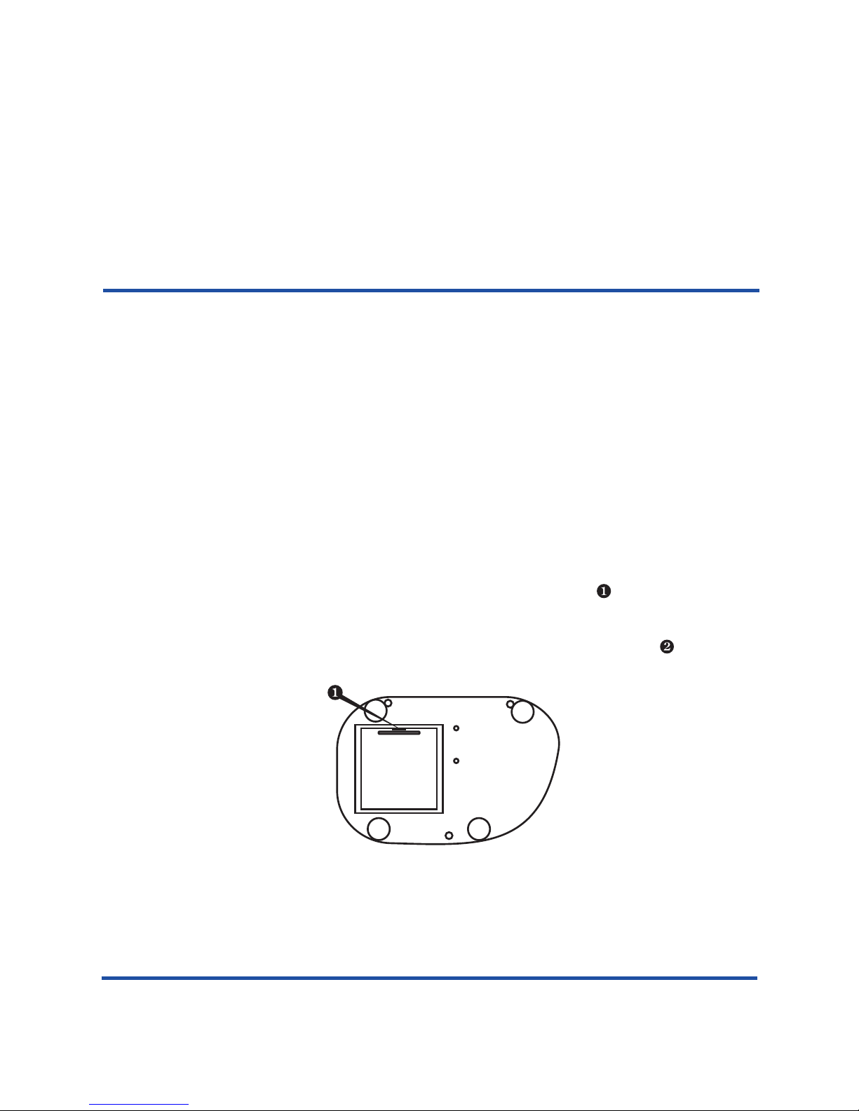
·Battery set up:
-Insert a sharp pin into the small socket according to the fig.1/ on the underside and
open the battery compartment.
-Insert the batteries inside matching correctly +/- poles.
·Alternatively connect the external power supply unit to the socket (fig.2/ ) on the rear
side of the unit.
3.4 Calibration
Declaration of Conformity
3.3 Set up:
Place the unit on the horizontal even working surface;
The instrument is pre-calibrated at the factory for operation with the glass tubes external diam.
18 or 16 mm (see the label on the bottom side of the unit) at temperature range from +15°C to
+25°C and keeps calibration without power supply.
Fig.1 Bottom scheme
Page 8
DEN-1B
Operating instructions
Version 1.01 - June 2012

Note! For work with other type tubes (e.g. with different outer diameter, bottom shape or different
material [transparent plastic tubes]) it is necessary to perform calibration in the specified
tubes.
Perform calibration
3.4.1.
3.4.2. Switch ON the unit with the Power switch (Fig.2/ ) on the rear panel (position I).
, not more than 2 mm diameter
point is saved in the memory and the
next calibration value is displayed .
in the following sequence from the lower calibration value to the higher
values: 0.0, 0.5, 1.0, 2.0, 3.0, 4.0, 5.0, 6.0. The minimum requirement is to calibrate 2 points.
Attention! Ensure that the tube socket is empty!
If external power supply is used, connect it to the mains.
3.4.3. With a pin press Select button (fig.2/ ) on the backside of the unit (for Select and Install
buttons use thin pin ). The display indicates flashing figure "- - -"
the unit is ready to save calibration value of the first point - empty socket.
3.4.4. With a pin press Install button (fig.2/ ), “Empty socket”
(flashing figure "0.0”)
Note! Shake the tube with the corresponding standard, if necessary (it is recommended to
use vortex, e.g. Vortexer PV-1, for shaking).
3.4.5. Insert the tube with the calibration value corresponding standard into the socket (fig.3/ ) of
Densitometer.
3.4.6. With a pin press Install button. This point of calibration sequence is saved in the memory and
the next calibration value is displayed.
Note! It is recommended to calibrate 0 value and as many points as possible to obtain precise
results. The minimum requirement is to calibrate 2 points closest to working range (e.g.
0 and 6.0 for operation in 0 - 6.0 McF unit range).
3.4.7. Repeat steps 3.4.5.-3.4.6. until the calibration is complete (1-7 times, i.e. as many times as
many points the chosen calibration sequence has).
3.4.8. If a standard is not available, press Select button for the next calibration value to be displayed.
3.4.9. After installing the last standard value “6.0”, or skipping it (Select button), the unit enters
operation mode. The unit is ready for operation.
Note! If during calibration pressing of Install button does not cause switch to the next Standard
value, it means that the inserted in the densitometer socket Standard has lower turbidity
value than the previous Standard. Cause: turbidity of the inserted Standard does not
correspond to the necessary value (Standard has to be shaken or replaced).
3.4.10. At the end of calibration switch OFF the unit with the Power switch (position O). If external
power supply is used, disconnect the external power supply from the mains.
Fig.2 Rear panel
Power DC-12
Calibration
select
install
Page 9
DEN-1B
Operating instructions
Version 1.01 - June 2012

4. Operation of DEN-1B
Recommendations during operation
Remove the tube with measured solution before connecting or disconnecting the external
power supply during operation.
It is recommended to start operation after approximately 15 min (the time necessary for
stabilisation in the working mode).
Using a tube with a flat bottom, the fluid should exceed the 7 mm level from the tube bottom,
using a round-bottom tubes - 12 mm level from the tube bottom.
The display goes off, if no tube is inserted in the socket during one minute. Press On key
(fig.3/ ) to activate the unit.
4.1 If external power supply is used, connect it to the mains socket.
4.2 Switch ON the unit with the Power switch (Fig.2/ ) on the rear panel.
4.3 The following indication will be shown on the display (fig.3/ ):
“0.00” - the unit is calibrated and ready for operation (if no any tube inserted);
·
·
·
·
Fig.3 General view
On
Page 10
DEN-1B
Operating instructions
Version 1.01 - June 2012

DEN-1B
Operating instructions
Page 11
“CC”(flashing) - the unit is not calibrated - calibrate the unit.
“LOW BATTERY” - change the batteries following the Batteries instructions in p. 1. Safety
precautions.
4.4 Shake the tube with the solution (it is recommended to use vortex for shaking, e.g.
Vortexer PV-1) and insert into the socket (fig.3/ ). The McFarland value for the solution
will be shown on the display (fig.3/ ).
4.5 Glass and transparent plastic tubes (external diameter 16 mm and 18 mm) can be used
for work with Densitometer. An adapter D16 must be used for work with tubes which have
external diameter 16 mm.
Note! The unit must be calibrated each time a tube type is changed (e.g. with different
outer diameter, bottom shape or different material [transparent plastic tubes]).
4.6 At the end of operation switch OFF the unit with the Power switch. If external power
supply is used, disconnect it from the mains socket.
Version 1.01 - June 2012

Page 12
DEN-1B
Operating instructions
5. Maintenance
Cleaning
Do not use solvents.
Before using any decontamination or cleaning method except that recommended, check
with our Service Department, or in other countries with our distributor, that the proposed
method will not damage the equipment.
The cases can be cleaned with a damp cloth after disconnection.
Version 1.01 - June 2012

DEN-1B
Operating instructions
Page 13
6. Specifications
The product is designed for operation indoors in a laboratory at altitudes up to 2000m, with ambient
temperature from +4°C to +40°C and maximum relative humidity 80% for temperatures up to 31°C
decreasing linear ly to 50% relative humidity at 40°C.
• Light source ..........................................................................................................................LED
• Wavelength ..........................................................................................................λ = 565 ±15 nm
• McFarland unit range ....................................................................................................0.0 - 15.0
• Accuracy, of the full scale......................................................................................................+ 3%
• Display resolution ......................................................................................................... 0.01 McF
• Measurement time ..............................................................................................................1 sec
• Recommended external diameter of tube ..........................................................................18 mm
16 mm (when using D16 adapter)
• Sample volume..................................................................................................not less than 2 ml
• Display .................................................................................................................................LCD
• Input current/power consumption ......................................................................12V, 7 mA / 0.1 W
• External power supply............................................. input AC 100-240 V 50/60Hz, output DC 12V
• Battery ....................................................................................................3 x accumulator AA type
• Dimensions .......................................................................................................165x115x75 mm
• Weight with power supply, not more ....................................................................................0,9 kg
Grant is committed to a continuous programme of improvement, specifications may be changed
without notice.
DescriptionReplacement part
Adapter for tubes with external diameter 16 mmD16
Version 1.01 - June 2012

Page 14
DEN-1B
Operating instructions
7.1 Guarantee
When used in laboratory conditions and according to these working instructions, this
product is guaranteed for TWO YEARS against faulty materials or workmanship.
7.2 Service
For service, return for repair to our Service Department in the UK or, in other countries,
to our distributor.
7. Guarantee and Service
Version 1.01 - June 2012

DEN-1B
Operating instructions
Page 15
Version 1.01 - June 2012

-bio
Densitometer/DEN-1B/30082/1.01
Grant Instruments
(Cambridge) Ltd
Shepreth
Cambridgeshire
SG8 6GB
UK
Tel: +44 (0) 1763 260811
Fax: +44 (0) 1763 262410
Email: labsales@grantinstruments.com
www.grantinstruments.com
 Loading...