

Grant Vortex Eco VTXWH12/16, Vortex Eco Series, Vortex Eco VTXWH16/21, Vortex Eco VTXSWH12/16, Vortex Eco VTXSWH16/21 Installation And Servicing Instructions
Page 1

Grant Vortex Eco
Internal Wall Hung
Condensing Oil Boiler Range
Installation and Servicing Instructions
UK | DOC 0126 | Rev 1.1 | October 2018
Page 2

IMPORTANT NOTE FOR INSTALLERS
These instructions are intended to guide installers on the
installation, commissioning and servicing of the Grant Vortex oil
boiler. After installing the boiler, leave these instructions with the
user.
A user handbook is available to guide users in the operation of the
oil boiler.
SPECIAL TEXT FORMATS
The following special text formats are used in these instructions
for the purposes listed below:
! WARNING !
Warning of possible human injury as a consequence of not
following the instructions in the warning.
! CAUTION !
Caution concerning likely damage to equipment or tools
as a consequence of not following the instructions in the
caution.
! NOTE !
Used for emphasis or information not directly concerned
with the surrounding text but of importance to the reader.
PRODUCT CODES AND SERIAL
NUMBERS COVERED
The serial numbers used on Grant oil boilers consist of a fteen
digit numerical code with the nal three digits being the product
identier.
For example:
100000200218767
These instructions cover the following product codes and serial
numbers:
Product code Serial number identier
VTXWH12/16 767
VTXWH16/21 769
VTXSWH12/16 768
VTXSWH16/21 770
SERVICING
The boiler should be serviced at least every twelve months and
the details entered in the Service Log in the user handbook.
FUEL TYPE
All Grant Vortex boilers are suitable for use with Class C2
Kerosene. To use Bio-Kerosene (B30K), refer to the information
below:
OPERATION ON BIO-FUEL
All Grant Vortex condensing boilers manufactured since May 2011
are suitable for operation on both standard Kerosene (Class C2 to
BS 2869) and also bio-kerosene - up to a 30% blend (B30K).
All burner settings and nozzle sizes (as detailed in Section 2.2 of
these instructions) are correct for both standard kerosene and biokerosene (B30K).
In order to operate this boiler on bio-kerosene, it will be necessary
to take the following actions:
• Use a bio-kerosene (B30K) compatible exible oil line in
place of the oil line supplied with the boiler.
• Have the oil storage tank and oil supply line (including all
pipework, sight gauges, lters, isolating valves, re valves,
de-aeration devices, etc.) checked for their compatibility with
bio-kerosene (B30K).
Where necessary, some or all of these items may have to be
replaced with a bio-kerosene compatible alternative.
• Check the suitability of the ue system with Grant UK.
• Use only bio-kerosene (B30K) that conforms to OPS24.
IMPORTANT:
Under no circumstances, should the boiler be used with
bio-kerosene without the above actions being taken rst.
GRANT ENGINEERING (UK) LIMITED
Hopton House, Hopton Industrial Estate, Devizes, Wiltshire, SN10 2EU
Tel: +44 (0)1380 736920 Fax: +44 (0)1380 736991
Email: [email protected] www.grantuk.com
This manual is accurate at the date of printing but will be superseded and should be disregarded if specifications and/or appearances are changed in the interests of continued product improvement.
However, no responsibility of any kind for any injury, death, loss, damage or delay however caused resulting from the use of this manual can be accepted by Grant Engineering (UK) Limited, the
author or others involved in its publication.
All good sold are subject to our official Conditions of Sale, a copy of which may be obtained on application.
© Grant Engineering (UK) Limited. No part of this manual may be reproduced by any means without prior written consent.
Page 2
Page 3

CONTENTS
1 INTRODUCTION 4
1.1 How a condensing boiler operates 4
1.2 Boiler description 4
1.3 Flue options 4
1.4 Boiler components 5
2 TECHNICAL DATA 6
2.1 Boiler technical data 6
2.2 Sealed system data 6
2.3 Burner settings 7
2.4 Flue gas analysis 7
2.5 Water connections 7
2.6 Boiler dimensions 8
3 OIL STORAGE AND SUPPLY SYSTEM 9
3.1 Fuel supply 9
3.2 Burner oil connection 11
4 INSTALLATION 13
4.1 Introduction 13
4.2 Boiler location 13
4.3 Regulations 13
4.4 Heating system design 13
considerations
4.5 Pipework materials 14
4.6 Connections 14
4.7 Preparation for installation 14
4.8 Dismantling the boiler 14
4.9 Installing the boiler 16
4.10 Before you commission 17
4.11 Completion 17
5 PIPE CONNECTIONS 18
5.1 Water connections 18
5.2 Water connections - system models 18
6 CONDENSATE DISPOSAL 19
6.1 General requirements 19
6.2 Connections 19
6.3 Pipework 19
6.4 External pipework 19
6.5 Condensate soakaway 20
6.6 Condensate trap 20
6.7 Condensate disposal pipework 20
6.8 Inspection and cleaning of trap 20
9 FLUE SYSTEM AND AIR SUPPLY 28
9.1 Air supply 28
9.2 Conventional ue systems 28
9.3 Connecting a conventional ue 31
9.4 Balanced ue systems 31
9.5 Prepare the wall 35
9.6 Flue clearances 36
10 COMMISSIONING 38
10.1 Before switching on 39
10.2 Burner settings: 39
10.3 Switching on 40
10.4 Running the boiler 41
10.5 Balancing the system 41
10.6 Completion 41
11 SERVICING 42
11.1 Checks before servicing 42
11.2 Dismantling prior to servicing 42
11.3 Cleaning the boiler 43
11.4 Cleaning the burner 43
12 FAULT FINDING 45
13 SPARE PARTS 48
14 DECLARATION OF CONFORMITY 50
15 HEALTH AND SAFETY INFORMATION 51
15.1 Insulation materials 51
15.2 Sealant and adhesive 51
15.3 Kerosene and Gas Oil fuels 51
16 END OF LIFE INFORMATION 52
17 PRODUCT FICHE 53
17 GUARANTEE 54
7 SEALED SYSTEMS 21
7.1 Sealed system requirements 21
7.2 Filling the sealed system 22
7.3 Venting the pump 22
7.3 Pressure relief (safety) valve 22
operation
8 ELECTRICAL 23
8.1 General 23
8.2 Connecting the power supply 23
8.3 Frost protection 23
8.4 Control system wiring diagrams 24
8.5 Boiler control panel wiring diagrams 26
Contents Page 3
Page 4

1 INTRODUCTION
1.1 HOW A CONDENSING BOILER
OPERATES
During the combustion process, hydrogen and oxygen combine
to produce heat and water vapour. The water vapour produced
is in the form of superheated steam in the heat exchanger. This
superheated steam contains sensible heat (available heat) and
latent heat (heat locked up in the ue gas). A conventional boiler
cannot recover any of the latent heat and this energy is lost to the
atmosphere through the ue.
The Grant Vortex condensing boiler contains an extra heat
exchanger which is designed to recover the latent heat normally
lost by a conventional boiler. It does this by cooling the ue gases
to below 90°C, thus extracting more sensible heat and some of
the latent heat. This is achieved by cooling the ue gases to their
dew point (approximately 55°C).
To ensure maximum efciency, the boiler return temperature
should be 55°C or less, this will enable the latent heat to be
condensed out of the ue gases.
• The boiler will achieve net thermal efciencies of 100%.
To achieve maximum performance from the Grant Vortex boiler,
it is recommended that the heating system is designed so that a
temperature differential of 20°C between the ow and return is
maintained.
The Grant Vortex boiler will however still operate at extremely
high efciencies even when it is not in condensing mode and
therefore is suitable for tting to an existing heating system
without alteration to the radiator sizes. The boiler is capable of a
maximum ow temperature of 78°C.
1.2 BOILER DESCRIPTION
The Grant Vortex Eco Wall Hung range of automatic pressure jet
oil boilers have been designed for use with a fully pumped central
heating system with indirect domestic hot water cylinder.
They are not suitable for use with either a direct cylinder or a
‘primatic’ cylinder or gravity hot water.
The boilers are suitable for use on open vented or sealed central
heating systems. System models are supplied with the necessary
components factory tted. Refer to Section 7.
All boilers are supplied with the control panel and burner factory
tted.
All the models in the current Grant Vortex Pro range of boilers are
designed to comply with the maximum NOx emissions* under the
Energy-related Products Directive (ErP).
* From the 26th September 2018, the maximum NOx emissions
for all new oil red boilers (up to and including 400kW for both
new build and replacement boiler installations) is 120mg/kWh.
1.3 FLUE OPTIONS
The boilers can be connected to either a conventional ue system
or a balanced ue system, as required.
1.3.1 FOR CONVENTIONAL FLUE APPLICATIONS
Where a chimney is to be lined - Grant recommends the use
of the Grant ‘Orange’ ue system, specically designed for the
Vortex range of condensing boilers. Refer to Section 9.2 for
further details.
Where a rigid conventional ue - either internal or external - is
required, Grant recommends the use of the Grant ‘Green’ and
‘Orange’ ue system components. As no ue adaptor is supplied
with the boiler it will be necessary to purchase the Grant CF
adaptor kit in order to correctly connect this system to the boiler.
Flue adaptor kit (Grant product code: CFA15/70) is used for all
models as they all use the 100 mm ‘Green’ and ‘Orange’ system
components to construct a ue of maximum vertical height of 8
metres.
! NOTE !
The ue system materials and construction MUST be
suitable for use with oil-red condensing boilers. Failure
to t a suitable conventional ue may invalidate the
guarantee on the boiler.
1.3.2 FOR BALANCED FLUE APPLICATIONS
The following ue kits are available from Grant UK. Refer to
Section 9.4.
Yellow system
Standard low level concentric balanced ue - components
available:
• Low level concentric balanced ue short
• Extensions 225 mm, 450 mm and 675 mm
• 90° extension elbow
• 45° extension elbow
• 45° elbow
• Plume diverter kits
Green system
Standard external high level/vertical ue starter kit (room sealed) -
components available:
• External high level/vertical ue starter kit short (room sealed)
• Extensions 150 mm, 250 mm, 450 mm, 950 mm
• Adjustable extension 195 to 270 mm
• 45° elbow
• High level terminal
• Vertical terminal
White system
High level and vertical concentric balanced ue kit- components
available:
• Extensions 225 mm, 450 mm, 950 mm
• Adjustable 275 to 450 mm
• Vertical concentric balanced ue kit
• Extensions 225 mm, 450 mm, 950 mm
• Adjustable extension 275 to 450 mm
• 45° elbow
Red system
A exible vertical balanced ue system designed to be tted inside
an existing masonry chimney.
Consisting of three sections:
• Concentric white painted ue pipe connected to the boiler
• Vertical concentric exible ue (exible stainless steel ue liner
inside a stainless steel air inlet liner)
• Terminal assembly for chimney top mounting
Flue extensions and 45° elbows from the White system may be
used.
Fitting instructions for the Low level, High level and Vertical
balanced ue systems are supplied with the kits.
Section 1: IntroductionPage 4
Page 5

1.4 BOILER COMPONENTS
All burners are pre-set for use with kerosene and are supplied
ready to connect to a two pipe fuel supply system with a two
exible fuel lines and 3/8ʺ to 1/4ʺ BSP male adaptor supplied with
the boiler.
The temperature of the water leaving the boiler to heat the
radiators and hot water cylinder is user adjustable.
The boiler is tted with an overheat thermostat (which allows
it to be used on a sealed central heating system) which will
automatically switch off the boiler if the heat exchanger exceeds a
pre-set temperature of 110°C ± 3°C.
The control panel is tted with an ON/OFF switch, boiler
thermostat control knob and the manual reset button for the
overheat thermostat.
To access the controls, open the lower front panel by pulling it
down as shown in Figure 1-1.
Figure 1-2 shows the details of the control panel.
Figure 1-1: Boiler lower front panel in down position
Figure 1-2: Vortex Pro boiler control panel
Section 1: Introduction Page 5
Page 6

2 TECHNICAL DATA
2.1 BOILER TECHNICAL DATA
Table 2-1: Boiler technical data
Units
Water content
Weight - complete boiler (dry)
Weight - boiler shell only (dry)*
Maximum heat output (Kerosene)
Minimum ow rate (∆T=10°C) l/h 1,410 1,800 1,410 1,800
Minimum ow rate (∆T=20°C) l/h 730 900 730 900
Condensate connection Accepts 21.5 mm Ø polypropylene overow pipe
Flue diameter (conventional) mm 100
Waterside resistance ∆T=10°C mbar 28.5
Waterside resistance ∆T=20°C mbar 10.0
Maximum static head m 28
Minimum circulating head m 1
Boiler thermostat range °C 65 to 78
Limit (safety) thermostat shut off
temperature
Maximum casing temperature °C Less than 50
Electricity supply ~230 1ph 50Hz 5A fused
Burner motor power Watts 75
Absorbed motor power kW 0.155 0.143
Starting current Amps 2.7
Running current Amps 0.67
Oil connection ¼ʺ BSP male (on end of exible fuel hose)
Conventional ue draught
Maximum operating pressure sealed/open system
Maximum operating pressure pressure relief valve
Boiler type ON/OFF
* Weight of shell - without bafes and clean out door: 45.5kg
litre 11 11 11 11
gal 2.4 2.4 2.4 2.4
kg 91.1 91.1 98.0 98.0
lb 200.8 200.8 216.1 216.1
kg 56.5 56.5 56.5 56.5
lb 124.6 124.6 124.6 124.6
kW 16.5 21.0 16.5 21.0
Btu/h 56,300 71,700 56,300 71,700
°C 110 ± 3
mbar Minimum: 0.087 - Maximum: 0.37
in wg Minimum: 0.035 - Maximum: 0.15
bar 2.0
bar 2.5
Internal Wall Hung Internal System Wall Hung
12/16 16/21 12/16 16/21
2.2 SEALED SYSTEM DATA
Internal System 12/16 and 16/21
Heating system pressure (cold) Minimum 0.5 bar | Maximum 1.0 bar
Operating pressure of pressure relief valve 2.5 bar
Expansion vessel size (pre-charged at 1 bar) 8 litres
Maximum heating system volume (including boiler)* 85 litres
Cold water mains connection 15 mm compression (supplied)
Pressure relief valve discharge connection 15 mm compression (supplied)
* Based on vessel charge and system cold ll pressure of 0.5 bar
Section 2: Technical DataPage 6
Page 7

2.3 BURNER SETTINGS
Table 2-2: Burner settings
Boiler
models
(burner
type)
Internal and
Internal
System 12/16
(Ecoam
Max 1 LN
Vortex WM
12-16 ERP)
Internal and
Internal
System 16/21
(Ecoam
Max 1 LN
Vortex WM
16-21 ERP)
Notes:
‡ Flue gas VFR: Flue gas volumetric ow rate
1. The data given above is approximate only and is based on the boiler being used with a low level balanced ue.
2. The above settings may have to be adjusted on site for the correct operation of the burner.
3. Gas Oil is NOT suitable for use with Grant Vortex boiler range
4. The ue gas temperatures given above are ± 10%.
5. When commissioning, the air damper must be adjusted to obtain the correct CO2 level.
6. * Factory settings: 12/16 - 14kW, 16/21 - 18.7kW.
7. The combustion door test point may be used for CO2 and smoke readings only. Do not use this test point for temperature or efciency readings.
8. The installer must amend the boiler data label if the output is changed.
Heat output
(kW) (Btu/h)
12.7 40,900 0.40/80°S 7 0 - 1 EK 12-16 30.5 1.06 60 - 65 12.5 13.0
14.0 * 47,80 0 0.40/80°EH 9 0 - 1 EK 12-16 31.5 1.17 65 - 69 12.5 15.0
16.5 56,300 0.50/80°EH 8 0 - 1 EK 12-16 32.5 1.38 65 - 69 12.5 17.0
16.5 56,300 0.50/80°EH 7 0 - 1 EK 16-21 29.5 1.38 65 - 69 12.5 17.0
18.7 * 63,800 0.50/80°EH 10 0 - 1 EK 16-21 31.0 1.56 70 - 75 12.5 20.0
21.0 71,700 0.60/80°EH 8 0 - 1 EK 16 - 21 31.0 1.76 75 - 79 12.5 23.0
Nozzle
Oil
pressure
(bar)
Smoke
No.
Burner
head type
Distance
between
nozzle and
burner head
Fuel
ow rate
(kg/h)
Flue gas
temp.
(°C)
CO
(%)
2
Flue gas
VFR ‡
(m³/hr)
2.4 FLUE GAS ANALYSIS
To allow the boiler to be commissioned and serviced, the boiler is supplied with a combustion test point on the front cleaning door.
When this test point is used please note the following:
• The test point is for CO
• The boiler efciency and temperature must be taken from the ue test point on high level, vertical and conventional ue adaptors.
• Concentric low level ues do not contain a test point. The temperature and efciency readings must be taken from the ue terminal.
and smoke readings only.
2
2.5 WATER CONNECTIONS
Table 2-3: Water connections
Boiler model
All models 22 mm Push-t Tectite Fitted 22 mm Push-t Tectite Fitted
Size Fitting Supplied Size Fitting Supplied
Flow connection Return connection
Section 2: Technical Data Page 7
Page 8

2.6 BOILER DIMENSIONS
FRONT VIEW
TOP VIEW
BOTTOM VIEW
RIGHT SIDE VIEW
113
81
842
630,5
22
75
109
144
179
214
249
284
Oil
Flow
Return
Cold Mains
PRV
Condensate
Electricity
221
110
Flow
Return
Cold Mains
Electricity
23
109
179
144
214
BACK PANEL
221
87
128 375
102
419
BACK PANEL
221
87
128 375
102
630,5
73
100 100 290
842
419
*
Figure 2-4: Vortex Eco Internal and Internal System 12/16 and 16/21
Section 2: Technical DataPage 8
Page 9

3 OIL STORAGE AND SUPPLY SYSTEM
3.1 FUEL SUPPLY
3.1.1 FUEL STORAGE
The tank should be positioned in accordance with the
recommendations given in BS 5410-1 (Code of Practice for
Oil Firing - Installations up to 45kW output capacity for space
heating and hot water supply purposes). This gives details of the
requirements for suitable oil tank construction, tank installation,
tank bases, re protection and secondary containment.
For installations of greater than 45kW output capacity, the tank
should be installed accordance with BS 5410-2.
Oil storage tanks should comply with the following standards:
• Plastic tanks OFT T100
• Steel tanks OFT T200
! CAUTION !
A galvanised tank must not be used.
! NOTE !
Plastic tanks should be stood on a rm non-combustible
base that adequately and uniformly supports the weight of
the tank over its entire base area.
The tank capacity should be selected to suit the appliance rated
output. Refer to BS5410-1 for guidance.
3.1.2 FUEL PIPES
Fuel supply pipes should be either copper or steel. Galvanised
pipes or ttings should not be used.
Plastic oil supply pipe conforming to BS EN 14125 can be used
for underground pipe runs, but must not be used above ground.
All soft copper pipe connections should preferably be made using
ared ttings. If compression ttings are to be used, a suitable
pipe insert must be tted into the pipe end.
Soft soldered connections must NOT be used on oil supply
pipework.
Fuel supply pipework should be of a suitable diameter, depending
on the type of oil supply system being used. Refer to information
given in sections 3.1.3, 3.1.4 or 3.1.5.
Run pipes as level as possible to prevent air being trapped. Take
the most direct route possible from tank to burner whilst locating
the pipe where it will be protected from damage.
Pipes should be supported to prevent sagging and sleeved where
they pass through a wall.
A metal body fuel lter of no better than 70 μm (micron) must be
tted in the oil supply pipe close to the tank. This should be tted
with sufcient clearance around and below it to allow easy access
for maintenance.
An isolating valve should also be tted at the tank, before the lter,
to allow the oil supply to be shut off for the lter to be serviced.
A second lter (15 μm for Kerosene) must be located closer to the
burner to protect the burner pump and nozzle from contamination.
Refer to Figures 3-1 to 3-3.
A remote sensing re valve must be installed in the fuel supply
line in accordance with BS540-1.
A fusible wheelhead type combined isolating/re valve MUST
NOT be used in place of a remote sensing re valve.
The re valve must be located outside; just before the oil line
enters the building, with the re valve sensor located above the
burner.
A spring clip for mounting the sensor is provided with the boiler.
This should be xed with the screw provided, using the small hole
in the front panel of the boiler.
The re valve should be located after the second (15 micron) lter,
i.e. between the lter and the point at which the oil line enters the
building. Refer to Figures 3-1 to 3-3.
The re valve must have an operating temperature of between
90 and 95°C to avoid unnecessary nuisance shut-offs to the oil
supply.
Two exible fuel hoses, adaptors and ¼ʺ isolating valves are
supplied loose with the boiler, to make the final connection to the
burner with a two pipe or ‘Tiger Loop’ type de-aerator.
Metal braided flexible fuel hoses should be replaced ANNUALLY
when the boiler is serviced.
Long life flexible fuel hoses should be inspected annually and
replaced, if necessary, or after a maximum five years service life.
3.1.3 SINGLE PIPE (GRAVITY) SYSTEM (REFER TO FIGURE 3-1)
Head
(metres)
0.5 19 60 100
1 21 66 100
1.5 23 72 100
2 25 79 100
2.5 27 85 100
3 29 91 100
3.5 31 98 100
If the storage tank outlet is at least 300 mm above the level of the
level of the burner oil pump, a single pipe (gravity) system should
be used.
The maximum height of the oil level above the burner oil pump
when the tank is full, must not exceed four metres. If this height
is exceeded, a pressure reducing valve must be tted in the oil
supply pipe between the tank and the burner oil pump.
The maximum length of pipe run from the tank to the burner is
limited by the minimum head of oil (the height of the tank outlet
above the burner oil pump).
Ø 6 mm Ø 8 mm Ø 10 mm
Maximum pipe run (m)
3.1.4 TWO PIPE SYSTEM (REFER TO FIGURE 3-2)
Head
(metres)
0.5 15 47 100
1 13 41 99
1.5 11 34 84
2 9 28 68
2.5 7 22 53
3 5 15 37
3.5 - 9 22
If the storage tank outlet is below the level of the burner oil pump,
a two pipe (sub gravity) system can be used.
The return pipe should be at the same level as the tank outlet,
between 75 to 100 mm above the base of the tank. The return
pipe should be a sufcient distance from the tank outlet so as to
prevent any sediment disturbed by the return entering the supply
pipe from the tank.
A non-return valve should be tted in the supply pipe, along with
a re valve and lters (refer to section 3.1.2 - fuel pipes). A nonreturn valve should also be tted in the return pipe if the top of the
tank is above the burner oil pump.
The maximum suction height (from the tank outlet to the level of
the burner oil pump), must not exceed 3.5 metres.
The pump vacuum should not exceed 0.4 bar. Beyond this limit,
gas is released from the oil.
For guidance on the installation of top outlet fuel tanks and suction
oil supply pipe sizing, refer to OFTEC Technical Book 3: Storage
and Supply, available for purchase from OFTEC.
Ø 6 mm Ø 8 mm Ø 10 mm
Maximum pipe run (m)
Section 3: Oil Storage and Supply System Page 9
Page 10

123
2
6
12
9
7
4
8 5
4m Max
300mm
Min
7
123
2
6
12
9
7
4
8 5
4m Max
300mm
Min
123
2
6
12
9
7
4
11
3.5m Max
10
8 5
9
123
4m Max
12
8 5
Figure 3-1: Single pipe (gravity) system
7
9
12
8 5
Figure 3-2: Two pipe system
4
2
6
300mm
Min
11
4
2
6
10
123
3.5m Max
7
9
12 4
2
10
6
8 5
10
Figure 3-3: De-aeration device system
Key to oil supply diagrams
1 Oil tank 5 Heating ow and return 9 Burner
2 Isolating valve 6 Oil lter (15μm max. ltration size) 10 Non-return valve
3 Oil strainer 7 Fire valve sensor 11 De-aerator*
4 Fire valve to BS 5410 8 Oil pump 12 Appliance isolation valves
* Position of de-aeration device must be level with or above the oil pump
123
150mm
Section 3: Oil Storage and Supply SystemPage 10
3.5m Max
Page 11

3.1.5 SINGLE PIPE (SUCTION) SYSTEM WITH
DEAERATOR - (REFER TO FIGURE 3-3)
If the storage tank outlet is below the level of the burner oil pump,
an alternative to the two pipe (sub gravity) system is the single
pipe (suction) system using a deaerator, e.g. a ‘Tiger Loop’
device.
The deaerator creates a loop with the burner oil pump, with the oil
being circulated through the pump out to the deaerator and back
to the pump. Any air in the single pipe lift from the tank is removed
from the oil, collected in the deaerator and then discharged to
outside.
! WARNING !
To prevent any fuel vapour being discharged within
the building, the deaerator must be tted outside, in
accordance with BS 5410-1, unless it is specically
designed to be installed inside.
The de-aerator must be mounted vertically at the same level as
(or above) the burner oil pump. Refer to Figure 3-3.
3.2 BURNER OIL CONNECTION
The burner fuel pump is supplied factory set for use with a two
pipe oil supply system.
For ease of access to the burner oil pump connections, the burner
should be removed from the boiler as follows:
1. Unscrew and remove the single burner fixing nut from the
stud on the burner flange (at the top of the burner) using a 13
mm spanner. Retain the fixing nut for re-fitting the burner.
2. Rotate the burner clockwise and carefully withdraw the
burner from the boiler. Refer to Figure 3-5.
RETURN
FROM PUMP
SUPPLY
TO PUMP
Figure 3-4: Tiger loop de-aeration device
An external deaerator must not be tted within 500 mm of a ue
terminal.
Always follow the manufacturers installation instructions supplied
with the deaerator.
Tiger Loop
1/4" BSP female
connections
SUPPLY
FROM TANK
Figure 3-5: Burner removal
SINGLE PIPE (GRAVITY) SYSTEM
For use on a single pipe system, it is necessary to t the
‘horseshoe’ washer into the tapping in the pump. Refer to Figure
3-6.
Figure 3-6: Fitting/location of ‘hoseshoe’ washer
Section 3: Oil Storage and Supply System Page 11
Page 12

This page is intentionally left blank.
Section 3: Oil Storage and Supply SystemPage 12
Page 13

4 INSTALLATION
4.1 INTRODUCTION
The boiler is supplied already fully assembled in a carton which
is carefully packed with packing materials. As the boiler is wall
mounted all of the content of the boiler casing must be removed
with the packaging before installation can begin, to give access to
the rear xing panel.
The installation procedure therefore begins with unpacking and
dismantling of the packed boiler.
4.2 BOILER LOCATION
The boiler should be xed to a wall that is rm, at and vertical. It
does not require any special base provisions as the temperature
of the boiler casing is less than 50°C.
Sufcient clearance must be allowed at the front of and below the
boiler to remove the burner and bafes for servicing.
4.3 REGULATIONS
! NOTE !
Failure to install and commission appliances correctly may
invalidate the boiler guarantee.
Installation of a Grant Vortex boiler must be in accordance with
the following recommendations:
• Building Regulations for England and Wales, or the Building
Standards for Scotland, as appropriate.
• Any relevant local Byelaws which you must check with the
local authority for the area concerned.
• The Water Supply (Water Fittings) Regulations 1999 or
the Water Supply (Fittings) (Scotland) Byelaws 2014, as
appropriate.
• Applicable Control of Pollution Regulations.
• The following OFTEC requirements:
• OFS T100 Polythene oil storage tanks for distillate fuels.
• OFS T200 Fuel oil storage tanks and tank bunds for use
with distillate fuels, lubrication oils and waste oils.
Further information may be obtained from the OFTEC Technical
Book 3 (Installation requirements for oil storage tanks) and
OFTEC Technical Book 4 (Installation requirements for oil red
boilers).
The installation should also be in accordance with the latest
edition of the following British Standard Codes of Practice (and
any relevant amendments):
• BS 5410-1 (Code of practice for oil ring. Installations up
to 45 kW output capacity for space heating and hot water
supply purposes)
• BS EN 12828 (Heating systems in buildings. Design for
water-based heating systems)
• BS EN 12831-1 (Energy performance of buildings. Method
for calculation of the design heat load)
• BS EN 14336 (Heating systems in buildings. Installation and
commissioning of water-based heating systems)
• BS 7593 (Code of Practice for treatment of water in domestic
hot water central heating systems)
• BS 7671 (Requirements for Electrical installations, IET Wiring
Regulations)
• BS 7291 (Thermoplastics pipe and tting systems for hot and
cold water for domestic purposes and heating installations in
buildings. General requirements)
• BS 7074-1 (Application, selection and installation of
expansion vessels and ancillary equipment for sealed water
systems. Code of practice for domestic heating and hot water
supply)
• BS 2869 (Fuel oils for agricultural, domestic and industrial
engines and boilers. Specication)
4.4 HEATING SYSTEM DESIGN
CONSIDERATIONS
! WARNING !
Before starting any work on the boiler or fuel supply,
please read the Health and Safety information given in
Section 15.
To achieve the maximum efciency possible from the Grant Vortex
boiler, the heating system should be designed to the following
parameters:
RADIATORS:
• Flow temperature 70°C
• Return temperature 50°C
• Differential 20°C
Size radiators with a mean water temperature of 60°C.
Design system controls with programmable room thermostats
or use weather compensating controls to maintain return
temperatures below 55°C.
! NOTE !
The boiler should not be allowed to operate with return
temperatures of less than 40°C when the system is up to
temperature.
The use of a pipe thermostat is recommended to control the return
temperature when using weather compensating controls.
UNDERFLOOR:
• Flow temperature 50°C
• Return temperature 40°C
• Differential 10°C
In underoor systems, it is essential that the return temperature
must be maintained at or above 40°C to prevent internal corrosion
of the boiler water jacket.
Refer to Section 2.5 for the size and type of the connections and
Section 5 for the position of the connections.
OPEN VENTED SYSTEMS:
! NOTE !
The presence of ‘pumping over’ in an open vented heating
system connected to the Grant Vortex boiler will invalidate
the product guarantee.
Open vented systems must be correctly designed and installed.
The open safety vent pipe must be positioned to prevent ‘pumping
over’ (i.e. the discharge of water from the open safety vent pipe
into the feed and expansion cistern under the pressure created
by the circulator).For detailed information on the correct design of
open vented heating systems, and the correct location of the open
safety vent pipe, refer to the CIBSE Domestic Heating Design
Guide and OFTEC Technical Book 4 (Installation).
Section 4: Installation Page 13
Page 14

4.5 PIPEWORK MATERIALS
Grant Vortex boilers are compatible with both copper and plastic
pipe. Where plastic pipe is used it must be of the oxygen barrier
type and be the correct class (to BS 7291-1) for the application
concerned.
On either sealed or open-vented systems; where plastic pipe is
used a minimum of ONE metre of copper pipe (or as per pipe
manufacturers instructions) MUST be connected between both
the boiler ow and return connections and the plastic pipe.
! NOTE !
Do not connect plastic pipe directly to the boiler.
Grant UK does not accept any responsibility for any damage,
however caused, to plastic piping or ttings.
SEALED SYSTEMS
If plastic pipe is to be used, the installer must check with the
plastic pipe manufacturer that the pipe to be used is suitable for
the temperature and pressures concerned.
Plastic pipe must be Class S to BS 7291-1.
4.7 PREPARATION FOR
INSTALLATION
The following procedure must be performed before you can begin
dismantling the boiler for installation:
1. With the boiler on the pallet, open the carton and remove all
packing materials and the carton from the boiler.
2. Lift open lower front panel, slide panel to left or right and
detach from the boiler.
! WARNING !
When plastic pipe is used, the system MUST incorporate
a low level pressure switch to shut off power to the boiler
if the system pressure drops below 0.2 bar. A suitable low
pressure switch kit is available to purchase from Grant UK
(product code: MPCBS62).
UNDERFLOOR PIPEWORK
Plastic pipe may be used on underoor oor systems where the
plastic pipe is tted after the thermostatic mixing valve. Copper
tube must be used for at least the rst metre of ow and return
primary pipework between the boiler and the underoor mixing/
blending valves.
4.6 CONNECTIONS
4.6.1 FLOW AND RETURN CONNECTIONS
Refer to Section 5.
4.6.2 CONDENSATE CONNECTION
Grant Vortex Pro boilers are supplied with a factory-tted
condensate trap to provide the required 75 mm water seal in the
condensate discharge pipe from the boiler.
Refer to Section 6 for details of the condensate disposal pipework.
4.6.3 DRAIN COCK
A drain cock is tted at the bottom on the front of the boiler to
allow the heating system to be drained.
Figure 4-1: Boiler front panel open
3. Remove upper front panel. Pull bottom edge of panel sharply
upwards to disengage retaining clips and lift off from boiler
4. Remove internal packaging from within boiler casing.
5. Remove lling loop and exible oil hose packs from within
boiler.
4.8 DISMANTLING THE BOILER
Dismantle the boiler as follows, keeping all components, screws
and washers for re-assembly:
1. Slacken off hose clip on burner air inlet and remove snorkel
tube from boiler.
2. Unscrew earth wire from underside of top casing panel.
3. Slacken the three screws at rear of top casing panel.
Remove screws securing top panel to side panels.
Pull top front corner of side casing panel on both sides by 10
mm outwards to disengage tabs on top casing panel.
Pull top panel forwards to remove from boiler.
4. Disconnect plug from burner control box.
5. System model only – Disconnect plug from pump.
6. Unscrew inlet connection to condensate trap and remove
trap from boiler.
7. Remove retaining clip and thermostat phials from their pocket
(in right side of heat exchanger – below return connection).
Figure 4-2: Removing thermostat phials
8. System model only - Unscrew and disconnect pressure
gauge pipe from PRV body.
9. Slacken control panel retaining screws and remove control
panel from boiler.
Section 4: InstallationPage 14
Page 15

10. Remove the two screws securing right hand side panel to
bottom panel. Remove right hand side panel from boiler by
lifting upwards to disengage tabs.
11. Repeat procedure to remove left hand side panel from boiler.
12. Slacken the three screws at rear of bottom casing panel and
remove bottom panel from boiler.
13. System model only - Unscrew upper pump union and remove
pump, complete with ow pipe, from boiler.
Figure 4-4: Removing clean-out door
18. Remove bafes from boiler shell.
Figure 4-3: Removing ow and return pipe
14. Non-system model – Unscrew compression connection on
boiler shell and remove ow pipe from boiler.
15. Unscrew top right compression connection and remove
return pipe from boiler.
16. Using a 13mm socket, slacken burner retaining nut (on top
of burner). Rotate burner clockwise (towards rear of boiler),
pull burner to the right until burner head is clear of mounting
ange and remove burner from boiler.
17. Using 13mm spanner, unscrew the two clean-out door
retaining nuts and remove door from front of boiler shell.
Figure 4-5: Removing bafes from boiler shell
19. Undo retaining screw and nut and remove transit bracket
from top of boiler shell.
20. Push boiler shell upwards to disengage it from mounting
bracket on back panel of boiler taking care not to damage the
insulation on the side of shell.
21. Lift boiler shell away from back panel and stand it upright on
the four feet.
22. Unscrew and remove the two transit screws securing
mounting bracket and back panel to pallet.
Section 4: Installation Page 15
Page 16

4.9 INSTALLING THE BOILER
fixings supplied by Grant UK.
You are now ready to install the boiler.
The procedure is as follows:
1. If a back outlet ue system is to be used, remove the large
circular ue knock-out from back panel. If the rear outlet PRV
discharge is to be used, remove the knock-out from the back
panel (as shown in the gure below.
Figure 4-6: Installing the back panel
2. Locate and hold the back panel in the required position on
the wall. Check it is level using a spirit level on the top ange.
Mark position of the holes for the two keyhole slots. Remove
the back panel from the wall.
3. Drill and t wall xing plugs (supplied) in the two holes.
Fit the two screws (supplied) and mount the back panel on
the wall using the two keyhole slots.
Check again that the back panel is level before proceeding.
4. Mark the position of the four mounting bracket xings on to
the wall from the back panel. Also mark the positions of the
ow and return pipes, the cold mains (for lling loop), the
electrical power supply, and the condensate discharge pipe.
5. If using a back outlet ue and/or rear PRV outlet is to be
used, also mark these holes on to the wall.
Figure 4-7: Fixing the back panel
9. Unscrew and remove ue xing screw from ue outlet.
10. Lift the boiler shell and hang it on the mounting bracket –
ensuring that the mounting plates on either side of the shell
are fully located in the vertical slot of both mounting hooks.
11. Re-t the return pipe to top right hand connection on boiler
shell. Pass return pipe from system through hole in back
panel (either at top or bottom of panel, as required) and
connect to boiler return pipe.
! NOTE !
If side outlet ue is to be used (to either left or right) then
mark position as it may be necessary to cut ue hole
BEFORE installing boiler on to wall.
6. Remove the back panel from the wall. Drill the holes for the
mounting bracket xings and t the wall plugs provided. Drill
all other necessary holes. If required, core drill the wall for a
back outlet ue and drill a hole for the PRV discharge pipe.
Re-mount the back panel on the two keyholes slots.
7. Locate the mounting bracket on to the back panel, aligning
the four holes in the bracket with those in the back panel.
Ensure that the mounting ‘hooks’ are pointing upwards and
secure using the xings supplied with the boiler.
8. Check the mounting bracket is level.
Figure 4-8: Re-tting ow and return pipe
12. System model only - Re-t pump complete with ow pipe to
upper pump union on boiler shell. Ensure that rubber pump
union washer is tted. Pass ow pipe from system through
hole in back panel (either at top or bottom of panel, as
required) and connect to boiler ow pipe.
13. Non-system model – Re-t ow pipe to compression
connection on boiler shell. Pass ow pipe from system
through hole in back panel (either at top or bottom of panel,
as required) and connect to boiler ow pipe.
! NOTE !
It is recommended that the system ow and return pipes
are connected to the boiler at this point in the installation.
Two 22mm isolating valves are supplied for use with sealed
system models only. These must not be used on an open
vented system. These boiler isolating valves should be
located adjacent to the boiler in a convenient position.
14. Re-t burner. First remove burner securing nut, locate
burner head into hole in burner ange/boiler shell and locate
mounting screw through hole on top of burner. Re-t nut and
tighten to secure burner in place. Connect exible oil lines
Section 4: InstallationPage 16
Page 17

from oil supply pipework to burner. It is recommended that
the copper oil lines are installed at this stage while the side
panels are not in place.
15. Re-t bafes into boiler shell – ensuring they are in the
correct order (check marking on each bafe) as shown
below.
Figure 4-9: Re-tting bafes into boiler shell
16. Locate clean-out door onto the two studs, re-t nuts and
tighten to secure door in place.
17. If side outlet ue system is to be used, remove ue ‘knock-
out’ from either the left or right side casing panel, as required.
18. Re-t left hand casing panel locating tabs on rear edge
of panel into slots in back panel. Firmly push side panel
downwards to fully engage tabs.
19. Repeat process to re-t right hand casing panel.
20. Pass ue through hole in side panel and secure.
21. Re-t bottom casing panel and secure in place with screws
(with washers).
22. If top outlet ue system is to be used, remove the ue ‘knock-
out’ in both the top casing panel and the top ange of the
back panel.
Fit the boiler connector (supplied in the ue kit) to the top of
the boiler shell, ensuring it is rmly connected and making a
seal on the neoprene gasket.
Refer to ue installation instructions for further details.
23. Re-t top casing panel and secure in place with screws (with
washers). Ensure that the ends of the front ange t into the
slots in the top front of side panels.
24. System model only - Re-t expansion vessel onto bracket
inside right hand side panel and reconnect expansion vessel
hose to connection on front right hand side of boiler shell.
Ensure rubber sealing washer is tted.
25. Re-t control panel – locating xing screws into slots in front
ange of bottom panel. Tighten screws to secure.
26. Re-locate thermostat bulbs in pocket at rear right hand side
of boiler shell.
27. System model only - Re-connect pressure gauge to PRV and
tighten.
28. Re-connect burner plug.
29. System model only - Re-connect pump plug.
30. Re-t condensate trap. Connect condensate discharge pipe
to outlet of trap.
31. Re-t snorkel tube to air inlet connection on burner. Tighten
hose clip to secure.
32. If balanced ue system is tted, connect other end of snorkel
tube to air inlet spigot of ue system.
33. If a conventional ue system is used, locate other end of
snorkel in top of boiler, ensuring that inlet to tube is not
restricted.
34. Fit ue system to boiler – refer to ue system installation
instructions.
35. Re-t upper front casing panel – hook top edge over front
edge of top panel, locate pins into spring retaining clip on
each side panel and push rmly home to secure.
36. Re-t lower front panel – with the panel at 45° to vertical,
locate the tabs into the horizontal slots in front of bottom
panel. Slide to either left or right and lift into closed position
against magnetic catches.
4.10 BEFORE YOU COMMISSION
To avoid the danger of dirt and foreign matter entering the boiler
the complete heating system should be thoroughly ushed
out – both before the boiler is connected and then again after
the system has been heated and is still hot. This is especially
important where the boiler is to be installed on an older system.
For optimum performance after installation, the boiler and the
associated heating system must be ushed in accordance with
the guidelines given in BS 7593 (Treatment of water in domestic
hot water central heating systems). This must involve the use
of a proprietary cleaner, such as Sentinel X300 (new systems),
Sentinel X400 (existing systems), or Fernox Restorer.
After cleaning, it is vitally important that all traces of the cleaner
are thoroughly ushed from the system.
For long term protection against corrosion and scale, after
cleaning/ushing a suitable inhibitor should be added to the
system water, such as Sentinel X100 or Fernox MB-1, in
accordance with the manufacturers’ instructions.
Failure to follow the above will invalidate the guarantee.
If the boiler is installed in a garage or out house, in order to
provide further protection should there be a power failure in cold
weather, a combined anti-freeze and corrosion inhibitor can
be used such as Sentinel X500 or Fernox Alphi-11. Follow the
manufacturers’ instructions supplied to achieve the level of antifreeze protection required.
For details of the Sentinel Products visit www.sentinel-solutions.
net and for Fernox products visit www.fernox.com.
Grant UK strongly recommends that a Grant Mag One in-line
magnetic lter/s (or equivalent*) is tted in the heating system
pipework. This should be installed and regularly serviced in
accordance with the lter manufacturer’s instructions.
* As measured by gauss. The MagOne magnetic lter has a gauss
value of 12000.
4.11 COMPLETION
Following installation of the boiler, instruct the user in the
operation of the boiler, the boiler controls, the heating controls and
the safety devices.
Please ensure that the OFTEC CD/10 installation completion
report (provided with the boiler) is completed in full, leaving the
top copy with the user and retain the carbon copy for your own
records.
Ensure that the User Handbook (supplied with the boiler) is
handed over to the user.
Section 4: Installation Page 17
Page 18

5 PIPE CONNECTIONS
5.1 WATER CONNECTIONS
FLOW AND RETURN CONNECTIONS - ALL
MODELS
On all models a 22mm push-t connection is provided for both the
heating ow and return connections.
Holes are provided in the top and bottom casing panels to route
the pipework as required.
! CAUTION !
All pipes to be tted into the push-t connectors provided
should be cut using a pipe slicer or pipe cutter - to leave
the pipe ends with a slight radius and free from any burrs
or sharp edges. Pipes to be used with these ttings should
not be cut square using a hacksaw.
5.2 WATER CONNECTIONS -
SYSTEM MODELS
A 15 mm discharge pipe must be connected to the safety valve
outlet connection. The pipework between the safety valve and the
boiler must be unrestricted, that is, no valves. The discharge pipe
should be run to the outside of the building and terminate so that it
cannot cause injury to persons or property.
A 15 mm double check valve ballox type valve is provided on the
exible lling loop hose for connection of the cold mains supply to
the heating system.
The cold mains supply should terminate inside the boiler casing.
A drain cock is tted at the bottom on the front of the boiler to
allow the heating system to be drained.
The expansion vessel is connected via a exible hose to allow it
to be moved to gain access to the burner and condensate trap for
servicing.
When replacing the vessel, care should be taken to ensure that
the exible connecting hose is not twisted.
Figure 5-1: Non system boiler ow and return connections
Figure 5-2: System boiler ow and return connections
Section 5: Pipe ConnectionsPage 18
Page 19
32 mm waste pipe external to the building
and 50 mm from the bottom
away from the property.
6 CONDENSATE DISPOSAL
6.1 GENERAL REQUIREMENTS
When in condensing mode the Grant Vortex boilers produce
condensate from the water vapour in the ue gases.
This condensate is moderately acidic with a pH value of around
3.27 (similar to orange juice).
Provision must be made for the safe and effective disposal of this
condensate.
Condensate can be disposed of using one of the following
methods of connection:
Internal connection (preferred option)
• into an internal domestic waste system (from kitchen sink,
washing machine, etc.)
• directly into the soil stack
External connection
• into an external soil stack
• into an external drain or gulley
• into a rainwater hopper (that is part of a combined system
where sewer carries both rainwater and foul water)
• purpose made soakaway
All condensate disposal pipes must be tted with a trap - whether
they are connected internally or externally to a domestic waste
system/soil stack or run externally to a gully, hopper or soakaway.
6.2 CONNECTIONS
Connections into a rainwater hopper, external drain or gulley
should be terminated inside the hopper/drain/gulley below the grid
level but above the water level.
! CAUTION !
Condensate disposal pipes must not be connected
directly into rainwater downpipes or to waste/soil systems
connected to septic tanks.
Condensate should not be discharged into ‘grey water’ systems
that re-use water used in the home (not including water from
toilets).
It should be noted that connection of a condensate pipe to the
drain may be subject to local Building Control requirements.
6.3 PIPEWORK
Condensate disposal pipework must be plastic (plastic waste or
overow pipe is suitable).
! NOTE !
Copper or steel pipe is NOT suitable and MUST NOT be
used.
Condensate disposal pipes should have a minimum ‘nominal’
diameter of 22 mm (¾ʺ) - e.g. use 21.5 mm OD polypropylene
overow pipe.
Condensate disposal pipes must be tted with a fall (away from
the boiler) of at least 2.5° (~45 mm fall per metre run).
! NOTE !
Where it is not possible for the pipe to fall towards the
point of discharge - either internally into a waste system
or externally to a gulley (e.g. for boilers installed in a
basement), it will be necessary to use a condensate pump.
Condensate disposal pipes should be kept as short as possible
and the number of bends kept to a minimum.
Pipes should be adequately xed to prevent sagging, i.e. at no
more than 0.5 metre intervals.
6.4 EXTERNAL PIPEWORK
Ideally, external pipework, or pipework in unheated areas, should
be avoided. If unavoidable, external pipework should be kept as
short as possible (less than 3 metres) and 32 mm waste pipe
used to minimise the risk of ice blocking the pipe in freezing
conditions.
The number of bends, ttings and joints on external pipes should
be kept to a minimum to reduce the risk of trapping condensate.
! NOTE !
For boilers installed in an unheated area such as a loft,
basement, outhouse or garage, all condensate pipework
should be as ‘external’.
The pipework should be insulated using suitable
waterproof and weather resistant insulation.
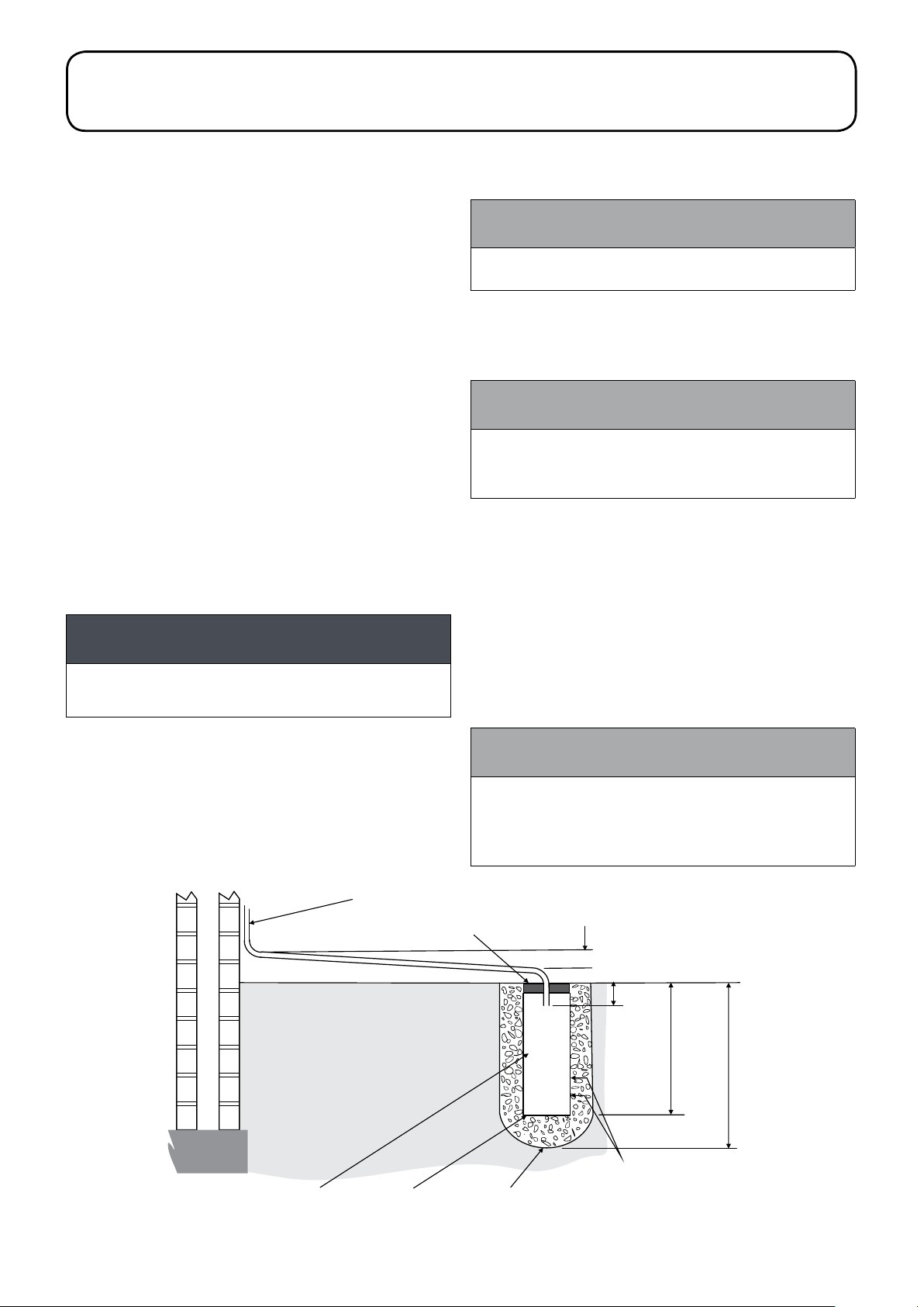
Cement seal
100 mm plastic tube
Figure 6-1: Purpose made condensate soakaway
Section 6: Condensate Disposal Page 19
Sealed end Backfill with 10 mm
limestone chippings
Minimum 2.5 fall
O
Ground level
25 mm
300 mm
400 mm
min.
Two rows of 3 x 12 mm
holes at 25 mm centres
of the tube. Holes facing
Page 20

6.5 CONDENSATE SOAKAWAY
To keep external pipework to a minimum, locate the soakaway
as close as possible to the boiler but ensure it is at least 500 mm
from building foundations and away from other services, e.g. gas,
electricity, etc.
The condensate pipe may be run above or below ground level
and can enter either the top or side of the soakaway tube. Refer
to Figure 6-1.
Ensure that the drainage holes in the soakaway tube face away
from the building.
Backll both the soakaway tube, and the hole around it, with 10
mm limestone chippings.
Only use a soakaway where the soil is porous and drains easily.
Do not use in clay soils or where the soil is poorly drained.
! CAUTION !
Any damage due to condensate backing up into the boiler
due to a high water table, in the case of a soakaway, or
ooded drains when the condensate disposal is via a
gulley or soil stack, is not covered by the Grant product
guarantee.
6.6 CONDENSATE TRAP
Grant Vortex boilers are supplied with a condensate trap to
provide the required 75 mm water seal in the condensate
discharge pipe from the boiler.
The condensate trap is factory tted inside the boiler casing -
mounted on the outlet of the condensing heat exchanger - in an
accessible position to allow for routine maintenance.
! NOTE !
With the trap tted inside the boiler casing, the sealing cap must
be tted. If the trap is re-located outside the boiler then the
following applies:
• If connecting the condensate discharge - either internally or
externally - into a waste system or soil stack - the sealing cap
must be tted in the trap outlet.
• On external discharge systems to a hopper, gully or
soakaway, the sealing cap should be removed from the trap
outlet.
• If there is any discharge of condensate from the overow
outlet, this could indicate a blockage (possibly due to
freezing). Turn off the boiler and investigate the cause. If
necessary contact your service engineer for assistance.
! WARNING !
Care should be taken when siting the trap such that the
overow outlet is readily visible and that any condensate
overowing from the outlet cannot cause either a hazard to
persons or damage to surrounding property or equipment.
6.7 CONDENSATE DISPOSAL
PIPEWORK
The condense trap outlet is at an angle of 48° below the
horizontal. This is to automatically gives a 3° fall on any
‘horizontal’ runs of condense disposal pipe. Refer to Figure 6-1
and see trap outlet/pipe.
The outlet of the trap will accept 21.5 mm to 23 mm OD
Polypropylene overow pipe for the condensate discharge pipe.
This discharge pipe can exit through the left side of the boiler
through one of two pre-cut ‘knock-outs’ in the lower part of the
left casing panel. Push out the ‘knock-out’ from the required hole
taking care not to distort the side panel.
If required, this condensate trap may be re-located outside
the boiler casing. Refer to the procedure given in Section
6.9. This procedure must be carried out before the boiler is
installed.
This trap incorporates a oat (which will create a seal when the
trap is empty) and an overow warning outlet (tted with a plastic
sealing cap), see Figure 6-2.
! NOTE !
When connecting plastic discharge pipe, ensure that the
pipe is fully pushed into the outlet end on the exible hose
to prevent the possibility of leakage.
6.8 INSPECTION AND CLEANING OF
TRAP
The trap must be checked at regular intervals (e.g. on every
annual service) and cleaned as necessary to ensure that it is clear
and able to operate.
The bottom bowl can be unscrewed from the trap body for
inspection and cleaning.
To inspect and clean the trap:
1. Disconnect exible condensate hose from inlet connector.
2. Unscrew the inlet connection nut.
3. Remove the inlet connector and nut from trap.
4. Disconnect the condensate disposal pipe from the trap outlet.
5. Remove trap from bracket.
6. Remove oat from trap – clean if necessary.
7. Inspect inside of trap and clean as necessary.
8. Re-assemble trap, re-t to boiler and re-connect exible
hose. Ensure that hose is fully pushed onto the trap inlet
connector.
Figure 6-2: Condensate trap
A ‘push-t’ elbow connects the outlet of the condensing heat
exchanger to the trap inlet. Ensure the elbow connector on the
hose is fully pushed onto the ‘top hat’ inlet connector of the trap.
! CAUTION !
Failure to regularly check and clean the condensate trap
may result in damage to the boiler and will not be covered
by the product guarantee.
Section 6: Condensate DisposalPage 20
Page 21
7 SEALED SYSTEMS
7.1 SEALED SYSTEM
REQUIREMENTS
All Grant Vortex Eco Wall Hung models are suitable for use with
sealed systems complying with the requirements of BS EN 12828,
BS EN 12831 and BS EN 14336.
The system must be provided with the following items:
• Diaphragm expansion vessel complying with BS EN 13831
• Pressure gauge
• Pressure relief (safety) valve
• Approved method for lling the system
7.1.1 EXPANSION VESSEL
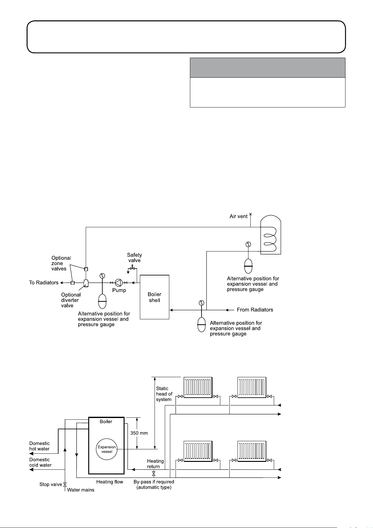
The expansion vessel should be tted in the return pipework
as shown in Figure 7-2. To reduce the operating temperature
of the expansion vessel, position it below the pipe to which it is
connected.
The expansion vessel may be positioned away from the system,
providing the connecting pipe is not less than 13 mm diameter. If
the expansion vessel is connected via a exible hose, care must
be taken to ensure that the hose is not twisted or kinked.
! NOTE !
Ensure that the expansion vessel used is of sufcient size
for the system volume.
Refer to BS 7074-1 or The Domestic Heating Design Guide
for sizing the required vessel.
7.1.2 PRESSURE GAUGE
The pressure gauge must have an operating range of 0 to 4 bar.
It must be located in an accessible place next to the lling loop for
the system.
7.1.3 SAFETY VALVE
The safety valve should be tted in the ow pipework near to the
boiler.
The pipework between the safety valve and boiler must be
unrestricted, i.e. no valves. The safety valve should be connected
to a discharge pipe which will allow the discharge to be seen, but
cannot cause injury to persons or damage to property.
7.1.4 FILLING LOOP
Provision should be made to replace water lost from the
Figure 7-1: Sealed system
If thermostatic radiator valves are
fitted, the system must incorporate an
adequate by-pass.
Figure 7-2: Sealed system boilers
Section 7: Sealed Systems Page 21
Page 22

system. This can be done manually (where allowed by the local
water undertaking) using an approved lling loop arrangement
incorporating a double check valve assembly.
The lling loop must be isolated and disconnected after lling the
system.
7.1.5 HEATING SYSTEM
The maximum ‘setpoint’ temperature for the central heating water
is 75°C. Refer to Section 1.1.
An automatic air vent should be tted in the ow and return pipes
of the highest point of the system.
If thermostatic radiator valves are tted to all radiators, a system
by-pass must be tted. The by-pass must be an automatic type.
All ttings used in the system must be able to withstand pressures
up to 3 bar. Radiator valves must comply with the requirements of
BS 2767.
One or more drain taps (to BS 2879) must be used to allow the
system to be completely drained.
7.2 FILLING THE SEALED SYSTEM
Filling of the system must be carried out in a manner approved by
the local Water Undertaking.
! WARNING !
Only ever ll or add water to the system when it is cold and
the boiler is off. Do not overll.
The procedure for lling the sealed system is as follows:
1. Check the air charge pressure in the expansion vessel
BEFORE lling the system.
The expansion vessel charge pressure should always be
slightly greater than the maximum static head of the system,
in bar, at the level of the vessel (1 bar = 10.2 metres of
water). Refer to Figure 7-2.
The charge pressure must not be less than the actual static
head at the point of connection.
operating the safety valve until the system design pressure is
obtained.
10. Close the ll point and double check valves either side of the
lling loop and disconnect the loop.
11. Check the system for water soundness, rectifying where
necessary.
7.3 VENTING THE PUMP
For those heating circulating pumps tted with a vent plug, it is
important that the pump is properly vented to avoid an air lock and
also prevent it running dry and damaging the bearings.
Unscrew and remove the plug from the centre of the pump motor.
Using a suitable screwdriver, rotate the pump spindle about one
turn. Replace the plug in the motor. Do not over tighten.
! NOTE !
Some heating circulating pumps are not tted with a
vent plug so it is not possible to vent these pumps in the
manner described above. Refer to pump manufacturers
own instructions for further details.
7.4 PRESSURE RELIEF (SAFETY)
VALVE OPERATION
Check the operation of the pressure relief (safety) valve as
follows:
1. Turning the head of the valve anticlockwise until it clicks. The
click is the safety valve head lifting off its seat allowing water
to escape from the system.
2. Check that the water is escaping from the system.
3. Top-up the system pressure, as necessary.
! NOTE !
The air charge pressure may be checked using a tyre
pressure gauge on the expansion vessel Schraeder valve.
The vessel may be re-pressurised, when necessary, using
a suitable pump. When checking the air pressure, the
water in the heating system must be cold and the system
pressure reduced to zero.
Check that the small cap (or screw) on all automatic air vents
is open at least one turn. The cap (or screw) remains in this
position from now on.
2. Ensure that the exible lling loop is connected and that the
double check shut off valve connecting it to the water supply
is closed. A valve is open when the operating lever is in line
with the valve, and closed when it is at right angles to it.
3. Open the ll point valve.
4. Gradually open the double check valve from the water supply
until water is heard to ow.
5. When the needle of the pressure gauge is between 0.5 and
1.0 bar, close the valve.
6. Vent each radiator in turn, starting with the lowest one in the
system, to remove air.
7. Continue to ll the system until the pressure gauge indicates
between 0.5 and 1.0 bar. Close the ll point valve. The
system ll pressure (cold) should be 0.2 - 0.3 bar greater
than the vessel charge pressure – giving typical system ll
pressures of approx 0.5 bar for a bungalow and 1.0 bar for a
two storey house.
Refer to the Domestic Heating Design Guide for further
information if required.
8. Repeat steps 4 and 5 as required until system is full of water
at the correct pressure and vented.
9. Water may be released from the system by manually
Section 7: Sealed SystemsPage 22
Page 23

8 ELECTRICAL
8.1 GENERAL
Grant Vortex Eco models requires a ~230V 1ph 50Hz supply. It
must be protected by a 5 Amp fuse.
Refer to Figures 8-1 to 8-4 for typical control system wiring
diagrams for all models.
Refer to Figures 8-5 and 8-6 for wiring diagrams for all models.
! WARNING !
The Vortex boiler contains electrical switching equipment
and must be earthed.
The supply must be fused at 5 Amp and there must only be one
common isolator for the boiler and control system, providing
complete electrical isolation.
A fused double pole switch or a fused three pin plug and shuttered
outlet socket should be used for the connection.
The power supply cable should be at least 0.75 mm
specied in BS 6500, Table 16.
All the wiring and supplementary earth bonding external to
the boiler must be in accordance with the current IET Wiring
Regulations.
Any room thermostat or frost thermostat used must be suitable for
use on mains voltage.
In the event of an electrical fault after installation of the boiler, the
following electrical system checks must be carried out:
• Short circuit
• Polarity
• Earth continuity
• Resistance to earth
2
PVC as
8.3 FROST PROTECTION
For additional protection of either the entire heating system, or
the boiler and localised pipework, it is recommended that a frost
thermostat be installed.
Refer to Figures 8-1 to 8-4 (as appropriate) for connection details.
To protect the heating system, the frost thermostat should be sited
within the house in such a place that it can detect any rise and fall
in the ambient air temperature, i.e. in a room with a radiator.
Where the frost thermostat is installed outside the house (to
protect a boiler installed in an external boiler room or garage) or
in an attic, it is recommended that it be used in conjunction with a
pipe thermostat to avoid unnecessary and wasteful overheating of
the property.
The pipe thermostat should be located on the boiler return pipe,
and set to operate at 25 C.
Refer to Figures 8-1 to 8-4 (as appropriate) for connection details.
8.2 CONNECTING THE POWER
SUPPLY
It is recommend that the boiler should be connected to a switched
mains power supply from a programmer or control system.
A three core cable is required to connect the boiler terminal block
to the live supply. Refer to Figures 8-1 to 8-4 for typical control
system wiring diagrams.
! NOTE !
Ensure that the route and length of the supply cable is
such that the boiler control panel can be hooked to the top
panel of the casing during the service operation.
The procedure is:
1. Remove the lower and upper front panels, if they have not
already been removed.
2. Remove the top of the control panel or the wiring cover (on
Kitchen models)and open the cable clamp.
3. Route the supply cable through the hole in the rear panel
(using the grommet supplied) up to the control panel, pass
it through the cable clamp and connect to the boiler terminal
block as follows:
• Brown to live (terminal 1)
• Blue to mains neutral (terminal 2)
• Green/Yellow to mains earth (terminal 3)
Section 8: Electrical Page 23
Page 24
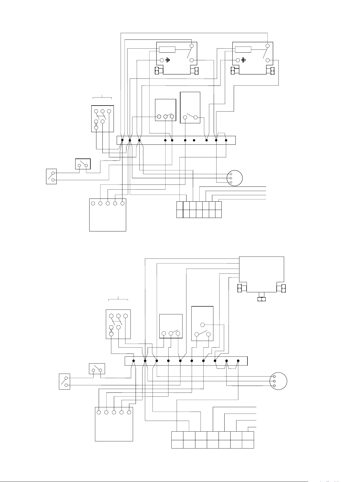
8.4 CONTROL SYSTEM WIRING DIAGRAMS
Grey
Blue
Grey
Motor Motor
Orange
Blue
DHWHTG
Frost
Thermostat
Pipe
Thermostat
(if fitted)
240 V
50 Hz
L
N E
1 3 4 N L
Green/Yellow
1 2
Brown
3 4 5 6 7 8 9 10
Zone Valve Zone Valve
Green/Yellow
Room Stat
2 1 1 C3
Cylinder
Stat
L N E L LE N
1 2 3 4 75 6
Boiler Terminal Block
Brown
wiring centre
E
Pump
N
L
Orange
L
E
N
L
Supply to
burner
Figure 8-1: Internal wall hung - 2 X 2-port valve control system
240 V
50 Hz
Blue
Green/Yellow
1 2
Frost
Thermostat
Pipe
Thermostat
(if fitted)
L
N E
Stat
1
Grey
Orange
White
Cylinder
Room Stat
2 1
3
3 4 5 6 7 8 9 10
C 2
Mid Position
Zone Valve
wiring centre
E
N
L
Pump
1 3 4 N L
Figure 8-2: Internal wall hung - 3-port valve control system
L N E L E N
1
2 3 4 5 6L7
Boiler Terminal Block
L
E
Supply to
N
L
Section 8: ElectricalPage 24
burner
Page 25
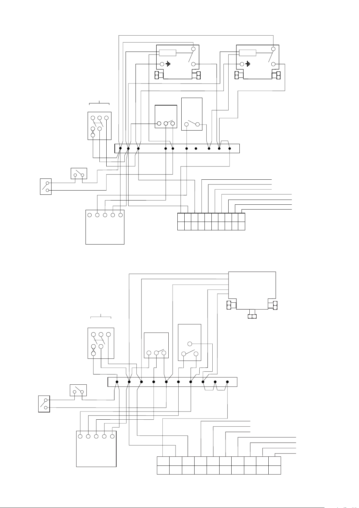
Figure 8-3: Internal system wall hung - 2 X 2-port valve control system
Frost
Thermostat
Pipe
Thermostat
(if fitted)
Grey
Blue
Blue
T6160
Room Stat
Brown
Brown
Green/Yellow
Green/Yellow
Grey
Orange
Zone Valve Zone Valve
Motor Motor
DHWHTG
Orange
L641
Cylinder
Stat
wiring centre
Supply to
burner
Boiler Terminal Block
Supply to
Pump
240 V
50 Hz
L
1 3 4 N L
N E
L N E L E N L LN E
1 2 3 4 7 8 9 105 6
1 2
2 1 1 C3
3 4 5 6 7 8 9 10
L
E
N
L
L
N
E
240 V
50 Hz
L
N E
Frost
Thermostat
Figure 8-4: Internal system wall hung - 3-port valve control system
Pipe
Thermostat
(if fitted)
1 3 4 N L
Section 8: Electrical Page 25
Blue
Green/Yellow
Room Stat
2 1
1 2
3 4 5 6 7 8 9 10
White
3
L N E L N E
1
Grey
Orange
Cylinder
Stat
1
C 2
2 3 4 5 6
Boiler Terminal Block
Mid Position
Zone Valve
wiring centre
E N L L
7 8 9 10
L
N
E
Supply to
Pump
E
N
L
L
Supply to
burner
Page 26
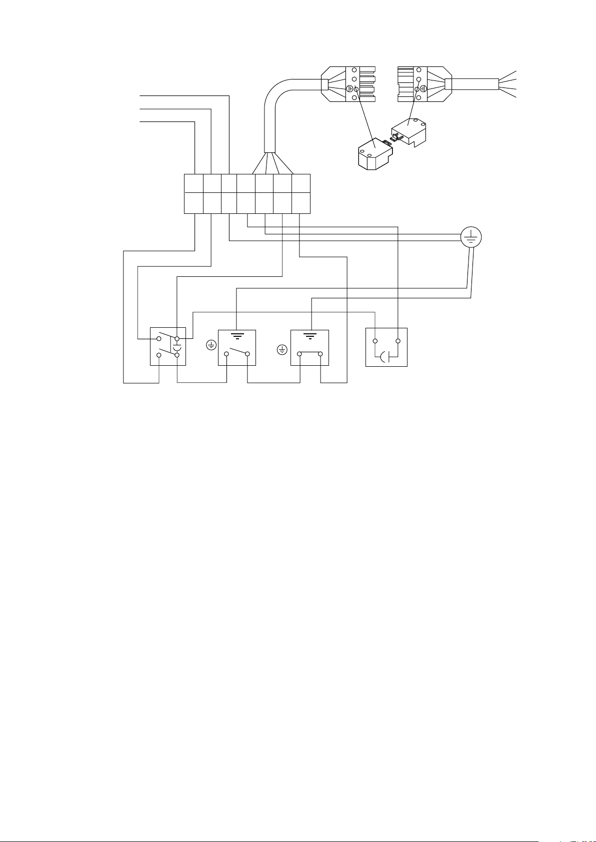
8.5 BOILER CONTROL PANEL WIRING DIAGRAMS
E
N
Mains Supply: Use
2 pole isolator with
power “ON” indicator
L
Brown
4B
Blue
1A
2A
Blue
Red
Green/Yellow
Blue
Brown
EL
N L2 E N L1
2 4 5 6 7
31
Yellow
Green/
1
C
5B
Blue
G/Y
4 core white
insulation
BrBlBlk
C
L2 L1
Blk
N
Bl
G/Y
Br
Fit covers as
above on plug
and socket
Black
Red
Blue
2
L2 L1
N
Bl
G/Y
Blk
Br
Green/
Yellow
Green/
Yellow
4 core white
insulation
Brown Brown
Boiler On/
Off
c/w neon
Figure 8-5: Internal wall hung - wiring diagram
Controlled
Thermostat
Limit
Thermostat
Lock out
Neon Red
Section 8: ElectricalPage 26
Page 27
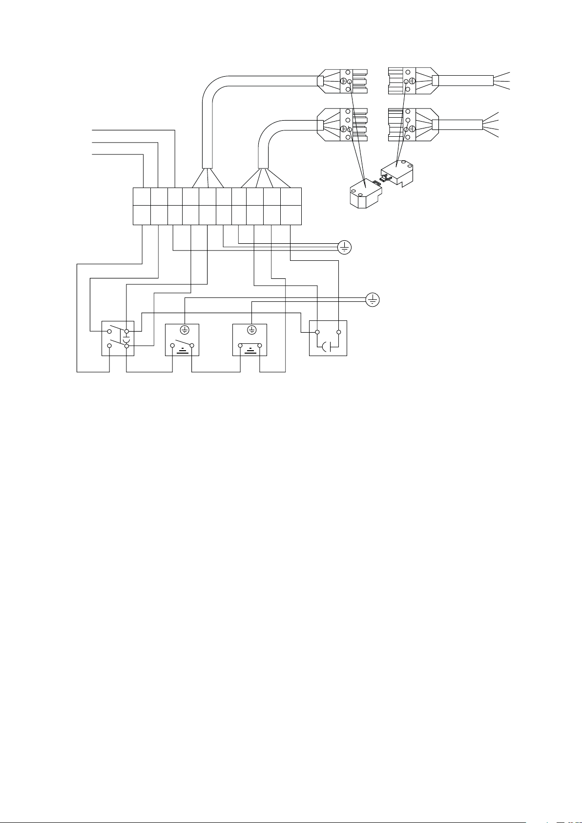
Mains Supply: Use
2 pole isolator with
power “ON” indicator
E
N
L
Brown
4B
Blue
1A
2A
Boiler On/
Off
c/w neon
Blue
Brown
Red
5B
Green/Yellow
Blue
Br BrBl Bl BlkG/Y
N L N E E N L1
2 4 5 6 7 8 9 10
31
Yellow
Green/
Green/
Yellow
Blue
1
C
BrownBrown
Controlled
Thermostat
Figure 8-6: Internal system wall hung - wiring diagram
G/Y
Blue
C
Limit
Thermostat
3 core white
insulation
4 core white
2
insulation
L2EL
Red
Blk
Bl
G/Y
Br
Green/
Yellow
Lock out
Neon Red
N
L1
L2 L1
N
Fit covers as
above on plug
and socket
Black
Green/
Yellow
Blk
Br
3 core white
insulation
4 core white
insulation
Pump
Burner
N
L1
L2 L1
N
Bl
G/Y
Section 8: Electrical Page 27
Page 28
9 FLUE SYSTEM AND AIR SUPPLY
9.1 AIR SUPPLY
A sufcient permanent air supply to the boiler should be provided
for the following reasons:
• For proper combustion of fuel and effective discharge of
combustion products to the open air.
• For the ventilation of any conned space in which the boiler
is installed to prevent overheating of the boiler and any
equipment in and near the boiler.
It should be both the designer’s and installer’s concern that the air
required for these functions be introduced so as to cause as little
discomfort as possible to the building occupants and thus to offer
them the least temptation to obstruct the ventilators.
Further details may be obtained from BS 5410-1.
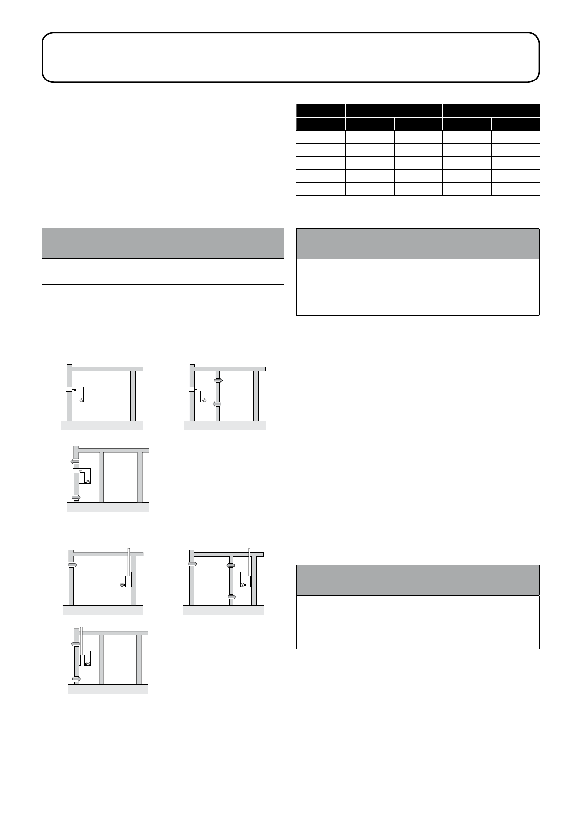
! NOTE !
For a boiler tted in a compartment, which is ventilated as
shown, no additional allowance is necessary.
Open ue - Extract fans, where needed, should be in accordance
with Section 5.4.7 in BS 5410-1.
All ventilation areas given are for domestic applications and relate
to the full output rating of the boiler.
For installations in older dwellings (constructed prior to the
introduction of Approved Document L1A 2006) the rst 5 kW of
output can be ignored. For all other cases refer to BS 5410-2.
B
B
Room sealed balanced flue no
ventilation required to room
A
A
Room sealed balanced flue
compartment ventilation from outside
Figure 9-1: Air supply for room sealed balanced ue boilers
C
Room sealed balanced flue
compartment ventilation from room
C
D
Table 9-3: Ventilation areas
Output 12/16 16/21
Area cm² in² cm² in²
Vent A 83 13 116 18
Vent B 165 26 231 36
Vent C 83 13 11 6 18
Vent D 165 26 231 36
Vent E 248 38 347 54
9.2 CONVENTIONAL FLUE SYSTEMS
! NOTE !
Under no circumstances can Grant Vortex boilers be
installed with existing ue systems. Only ue systems and
components suitable for wet ues should be used.
Failure to install the correct type of ue system will
invalidate the guarantee.
Grant condensing boilers have high operating efciencies and
low ue gas temperatures. Care must be taken to ensure the
ue system is suitable for the very low ue gas temperatures and
condensate in the ue gases.
Suitable conventional ue systems are available from Grant UK.
The ue must terminate in a down draught free area, i.e. at least
600 mm above the point of exit through the roof or preferably
above the ridge level.
The condensate may be allowed to run back into the boiler. A
condensate drain at the base of the ue system is not required.
The high level ue terminal must be at least 600 mm from
any opening into the building, and 600 mm above any vertical
structure or wall less than a horizontal distance of 750 mm from
the terminal.
If an existing chimney is to be used, it must be lined with a smooth
bore stainless steel liner suitable for use with oil red condensing
boilers. The top and bottom of the annular space must be sealed.
Grant recommends the use of the Grant ‘Orange’ ue system,
specically designed for the Vortex range of condensing boilers.
The internal ue and liner diameter for all models up to 46 kW
output must be 100 mm (4 in) and for the 46/58 and 58/70 models
125 mm (5 in).
The maximum vertical height (from the top of the boiler to the
terminal) for the ‘Orange’ system is 19 metres.
Conventional open flue Conventional open flue
C
D
Conventional open flue
compartment ventilation from outside
compartment ventilation from room
Figure 9-2: Air supply for conventional ue boilers
E
! NOTE !
The Grant Orange system exible stainless steel liner
is directional. The arrows marked on the liner MUST be
pointing vertically upwards, following the direction of the
ue gases. Failure to comply with this instruction could
lead to a leakage of condensate from the ue liner.
If a rigid ue is used externally, it must be of the twin-wall type
incorporating seals at all joints, constructed with a stainless steel
inner skin and be suitably insulated and weatherproofed. The
internal ue diameter for a rigid ue for all models - up to and
including the 58/70 - is 100 mm (4 in). Use the larger ‘200’ size of
‘Green’ system components as listed in Figure 9-14.
Grant recommends the use of the Grant ‘Green’ and ‘Orange’ ue
system components for this application. Refer to Section 1.3 for
details.
Section 9: Flue System and Air SupplyPage 28
Page 29
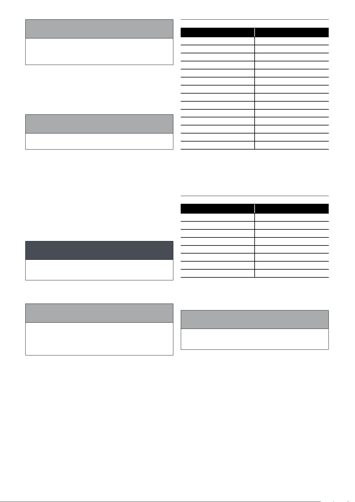
! NOTE !
As no ue adaptor is supplied with the boiler, in order to
correctly connect the hybrid system, it will be necessary
to purchase the Grant CF adaptor kit (product code:
CFA15/70).
If required, it is possible to use the white painted single-wall
straight ue extensions, adjustable extensions and elbows from
the Grant ‘Orange’ system for the internal section of the ue
system, see Figure 9-6. These components can be tted between
the boiler connector and ue adaptor. The ue adaptor, to which
the external twin-wall ‘Green’ ue components are connected, can
therefore be situated just before the ue system passes through
the wall.
! NOTE !
Grant ‘Orange’ system single-wall ue components must
not be used externally.
The maximum vertical height (from the top of the boiler to the
terminal) for the 100 mm diameter hybrid ‘Green/Yellow’ system is
8 metres.
Grant ‘Green’ twin-wall ue is recommended for externally run
ues to reduce the possibility of the condensate freezing in the
ue.
No part of any ue system should be made of an asbestos
material; aluminium must not be used in any part of the ue.
Only stainless steel ue components should be used.
If the draught conditions are satisfactory, the ue should terminate
with a standard cowl.
Refer to the locally applicable Building Regulations, BS 5410:1
and OFTEC Installation Requirements (OFTEC Technical Books 2
and 4) for further guidance on conventional ue systems.
! CAUTION !
Caution concerning likely damage to equipment or tools
as a consequence of not following the instructions in the
caution.
Only use ue systems suitable for oil red condensing boilers.
Do not use re cement. The use of high temperature silicone
sealants is recommended.
Table 9-4: Conventional ue kits
Product code Flexi pack (Orange system)
GFKIT 6/100 100 mm diameter x 6 metre
GFKIT 6/125 125 mm diameter x 6 metre
GFKIT 8/100 100mm diameter x 8 metre
GFKIT 8/125 125mm diameter x 8 metre
GFKIT 10/100 100mm diameter x 10 metre
GFKIT 10/125 125mm diameter x 10 metre
GFKIT 11/100 100mm diameter x 11 metre
GFKIT 11/125 125mm diameter x 11 metre
GFKIT 12/100 100mm diameter x 12 metre
GFKIT 12/125 125mm diameter x 12 metre
GFKIT 14/100 100mm diameter x 14 metre
GFKIT 14/125 125mm diameter x 14 metre
GFKIT 16/100 100mm diameter x 16 metre
GFKIT 16/125 125mm diameter x 16 metre
Extensions
A range of white powder coated single wall extensions are
available to connect the boiler to the exible liner.
The nominal diameter of the extensions is 100 mm or 125 mm.
Extensions are supplied with locking bands.
Table 9-5: Extensions
Product code Extensions (Orange system)
WX 150/100 100 mm diameter x 150 mm
WX 150/125 125 mm diameter x 150 mm
WX 250/100 100 mm diameter x 250 mm
WX 250/125 125 mm diameter x 250 mm
WX 450/100 100 mm diameter x 450 mm
WX 450/125 125 mm diameter x 450 mm
WX 950/100 100 mm diameter x 950 mm
WX 950/125 125 mm diameter x 950 mm
Flue extensions cannot be cut.
Also available are:
• An adjustable extension (235 to 300 mm)
• 45° elbow
! NOTE !
To comply with the requirements of the Building
Regulations Approved Document J - conventional ue
systems must have a ue data plate. A suitable data plate
is supplied with the Grant Orange ue system and should
be displayed next to the boiler or ue.
FLUE LINING KITS
Grant EZ-Fit Flexi Pack conventional ue system (Orange
System)
A range of Flexi pack conventional ue lining kits are available
from Grant UK. The packs have been specically produced for
Grant Vortex oil red condensing boilers.
The pack includes a terminal/top plate/exi ue adaptor, stainless
steel smooth bore exible ue liner, a rigid to exi adaptor and a
boiler ue connector.
Two diameters are available, a 100 mm for models up to 46 kW
and 125 mm for models above 46 kW.
! NOTE !
The rigid ue between the boiler and exible ue liner
should incorporate an adjustable section to allow
inspection and cleaning of the ue system.
Section 9: Flue System and Air Supply Page 29
Page 30
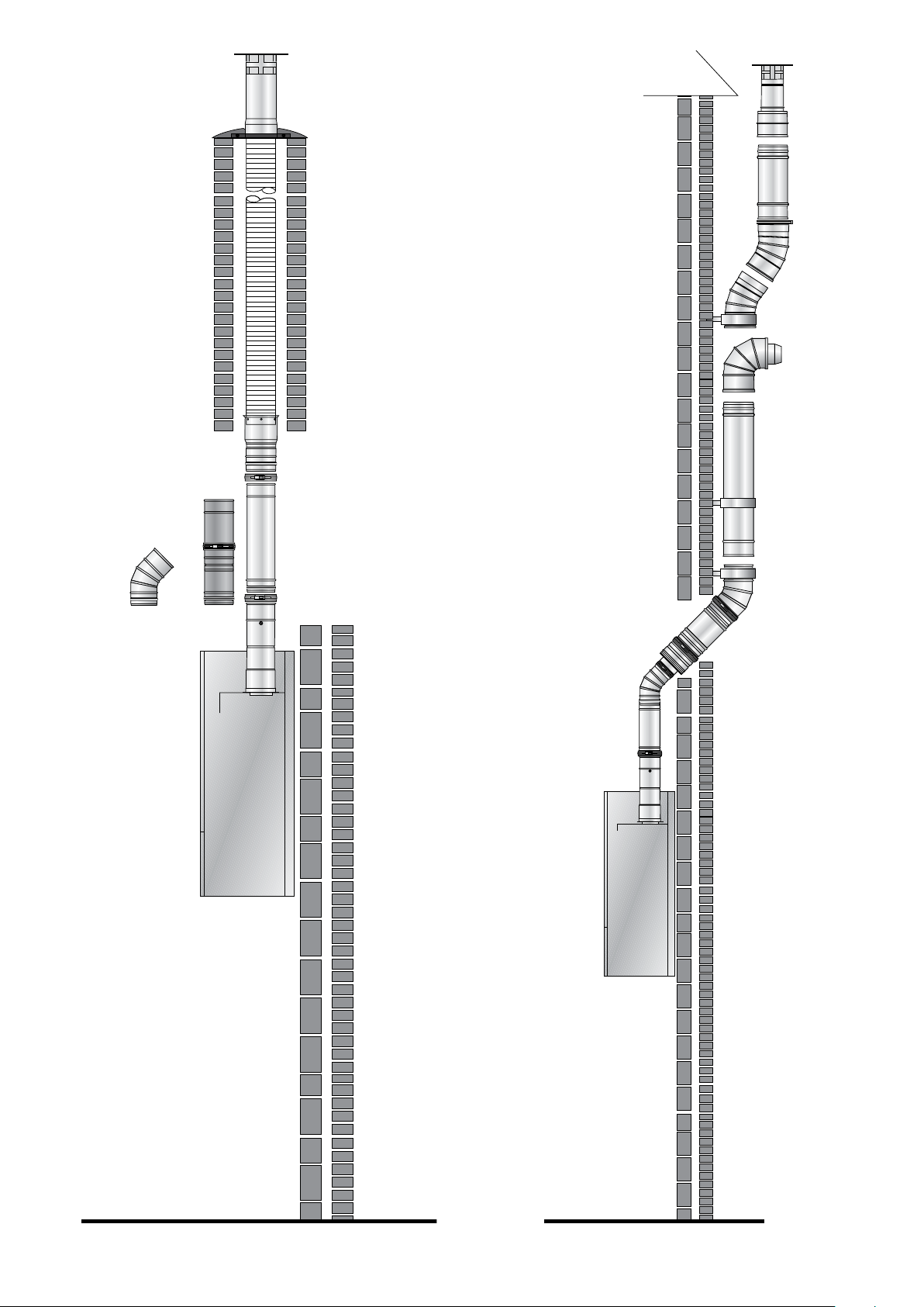
C
Figure 9-6: Grant Orange ue system in a typical brick chimney
Figure 9-7: Hybrid ue system using Grant Orange and Green
systems components
Section 9: Flue System and Air SupplyPage 30
Page 31
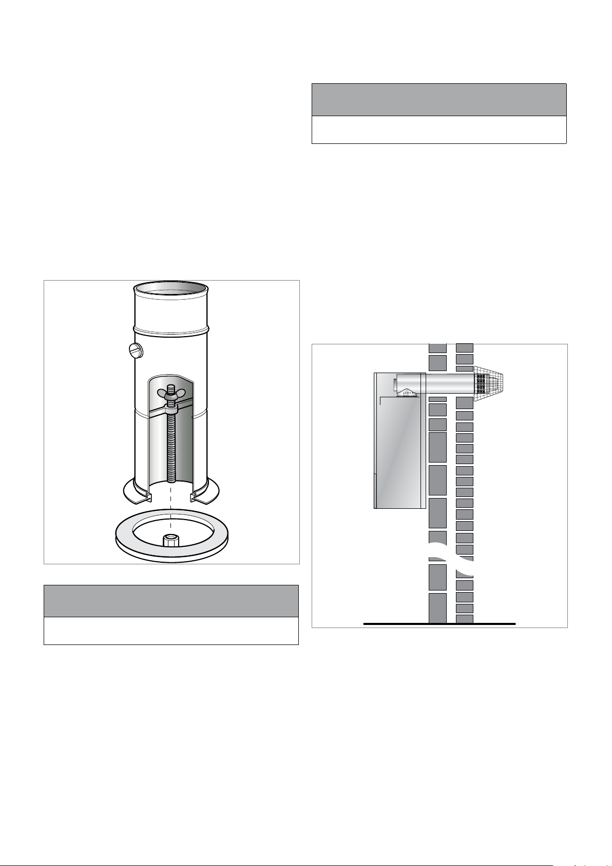
9.3 CONNECTING A CONVENTIONAL
FLUE
If the Grant ‘Orange’ ue system is being used – follow the
instructions supplied with the ue kit.
If the Grant ‘Green’ system (100 mm rigid twin-wall ue) is to be
tted to the boiler then the Grant CF adaptor kit (product code:
CFA15/70) must be used – refer to Section 1.3.
To t the adaptor kit, proceed as follows:
1. Fully screw the length of threaded studding (provided in the
kit) into the nut located in the centre of the boiler ue outlet.
2. Fit the boiler connector (from the CF adaptor kit) over the
threaded studding.
3. Position ange on to the neoprene gasket around the boiler
ue outlet, ensuring that small spigot on the base of the
connector is located in the hole in the centre of the neoprene
gasket and that end of studding passes through the hole in
the of the spacer bracket.
4. Fit washer and wing nut provided onto the end of threaded
studding and secure connector in position by tightening down
on wing nut – as shown in Figure 9-8.
5. Fit the ue adaptor (from the adaptor kit) into the boiler
connector.
9.4 BALANCED FLUE SYSTEMS
Apart from a conventional ue, several balanced ue options are
available for use with the Grant Vortex boilers.
All are suitable for use with Class C2 Kerosene.
! NOTE !
None of the flue sections in the following system can be cut.
LOW LEVEL HORIZONTAL BALANCED FLUE
(YELLOW SYSTEM)
Available in Short (for single thickness brick walls) and Standard
kits.
Extensions are available which extend the ue by 225 mm, 450
mm or 675 mm.
90° and 45° elbows are also available.
The maximum ue length - from the centre of the boiler ue outlet
to the outer face of the wall - is 4 metres (with or without elbows
included).
No more than 2 x 45 or 1 x 90 elbow should be tted per system.
The low level balanced ue (Yellow system) is supplied with a
stainless steel guard. This must be tted in all circumstances to
prevent objects from entering the ue outlet.
The guard must be tted centrally over the ue terminal and
securely xed to the wall.
Figure 9-8: Boiler ue connector
! NOTE !
Lubricate the seal on the adaptor using the lubricant
provided before attempting to t the ue adaptor.
6. Fit the rst section of ue into the ue adaptor and secure
using the clamp band provided.
7. Assemble the remainder of the ue system as required,
lubricating the seal on each component before tting.
Section 9: Flue System and Air Supply Page 31
Figure 9-9: Low level balanced ue
Page 32
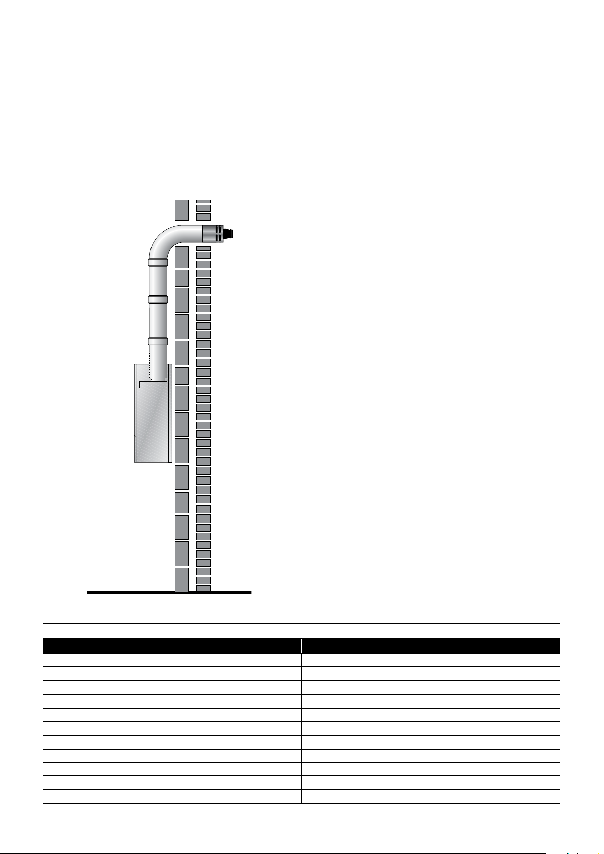
HIGH LEVEL (HORIZONTAL) BALANCED FLUE
(WHITE SYSTEM)
The High Level (horizontal) balanced ue (White system) allows
the ue to rise vertically within the building before exiting through
the wall horizontally.
The maximum ue length - from the top of the boiler ue outlet
to the outer face of the wall - is 10 metres for all Grant Vortex
boilers.
The following items are additionally available:
• Extensions to extend the ue by 225 mm, 450 mm or 950
mm.
• An adjustable extension of 275 to 450 mm.
• A 45° elbow - No more than 6 x 45° elbows should be tted
per system. Each elbow reduces the overall maximum length
of the system by 1 metre.
VERTICAL BALANCED FLUE (WHITE SYSTEM)
Allows the ue to rise vertically from the boiler to exit through the
roof.
The maximum ue length - from the top of the boiler ue outlet to
the terminal - is 12 metres for all Vortex boilers.
The following items are additionally available:
• Extensions to extend the ue by 225 mm, 450 mm or 950
mm.
• An adjustable extension of 275 to 450 mm.
• A 45° elbow - No more than 6 x 45° elbows should be tted
per system. Each elbow reduces the overall maximum length
of the system by 1 metre.
Figure 9-10: High level balanced ue
Table 9-11: White system components - product codes
Item 12/16 and 16/21 models
1.2 metre high level adjustable ue kit c/w 90° elbow and terminal HLK015090
Adjustable vertical 3 metre ue kit c/w terminal and storm collar VTK055090
225 mm extension EXTK31225/90
450 mm extension EXTK09450/90
950 mm extension EXTK11950/90
275 to 450 mm adjustable extension EXTK13ADJ/90
45° elbow ELBK2145/90
Pitched roof ashing - aluminium (VTK055090 and VTK0690200) VTMF200
Pitched roof ashing - lead VTK25P90 (includes collar)
Flat roof ashing - aluminium VTK27F90
Wall bracket BRK2990
Section 9: Flue System and Air SupplyPage 32
Page 33
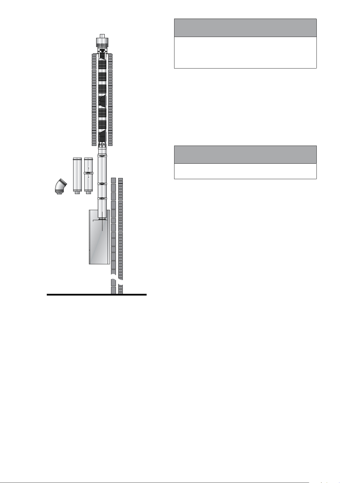
FLEXIBLE VERTICAL BALANCED FLUE (RED
SYSTEM)
! NOTE !
One mete of straight ue length should be deducted for
every elbow used. If the exible liner has to pass around
an offset in the chimney, two metres of straight ue length
should be deducted to compensate for this, i.e. equivalent
to two 45° elbows.
The Grant Red system exible stainless steel liner is directional.
The arrows marked on the liner MUST be pointing vertically
upwards, following the direction of the ue gases. Failure to
comply with this instruction could lead to a leakage of condensate
from the ue liner.
Flue extensions cannot be cut, use adjustable extensions where
required.
Three types of locking band are supplied with the kit.
The rst type is for connecting ue sections that butt together (2 of
this type of locking band are supplied).
The second type is to cover the joint on the adjustable (telescopic)
section.
! NOTE !
The locking band for the adjustable section is labelled for
easy identication.
The third locking band is plastic and supplied in two halves. This
is to secure the plastic exible liner to the adapter.
The ue kit includes a Black coated terminal with upstand and is
designed to be xed (using the screws provided) to the top of a
masonry chimney.
The ue system may be offset using 45° elbows (product code:
ELBK2145/90 models up to 26 kW output or ELBK22145/200 for
models 26 to 70 kW output).
No more than a maximum of four elbows should be used per
system.
Figure 9-12: Red system balanced ue
This is a exible vertical balanced ue system (for the 15/21
and 15/26 models only) designed to be tted inside an existing
masonry chimney. See Figure 9-12.
It basically consists of three sections:
• Concentric white painted ue pipe connected to the boiler.
• Vertical concentric exible ue (exible stainless steel ue
liner inside a exible plastic air inlet liner).
• Terminal assembly for chimney top mounting.
The ue pipe seals are factory tted and must be lubricated with
the lubricant supplied before assembly.
The Red system is supplied as a separate kit. Flue extensions
and 45° elbows from the White system may be used to extend the
ue between the boiler and the exible section of the system.
The maximum vertical straight length of ue, from the top of the
boiler to the top of the terminal, is 20 metres – using no more than
four 45° elbows. Deduct 1 metre of straight ue length for every
elbow used.
EXTERNAL BALANCED FLUE
(GREEN SYSTEM)
Where it is not practical to use a low level (Yellow system) or
internal high level/vertical (White system) balanced ue, the
boiler can be tted with an external vertical/high level ue (Green
system).
See Figure 9-13.
The Starter kit ts to the boiler in the same way as a low level
balanced ue (Yellow system) and the external Tee allows the
connection of a twin wall insulated ue pipe and a combustion air
inlet - providing a room sealed ue system.
The external system can terminate at either high level or vertically
(above roof level) as required.
See Figure 9-13.
The minimum dimensions for locating the terminal from building
features (windows, doors, etc.) are shown in Figure 9-15.
The terminal must be positioned so as to avoid products of
combustion accumulating in stagnant pockets around the
buildings or entering into buildings. Care should be taken that the
plume from condensed ue gases does not cause a nuisance.
The components listed on the following page for the external ue
(Green system) components are available from Grant UK.
Section 9: Flue System and Air Supply Page 33
Page 34
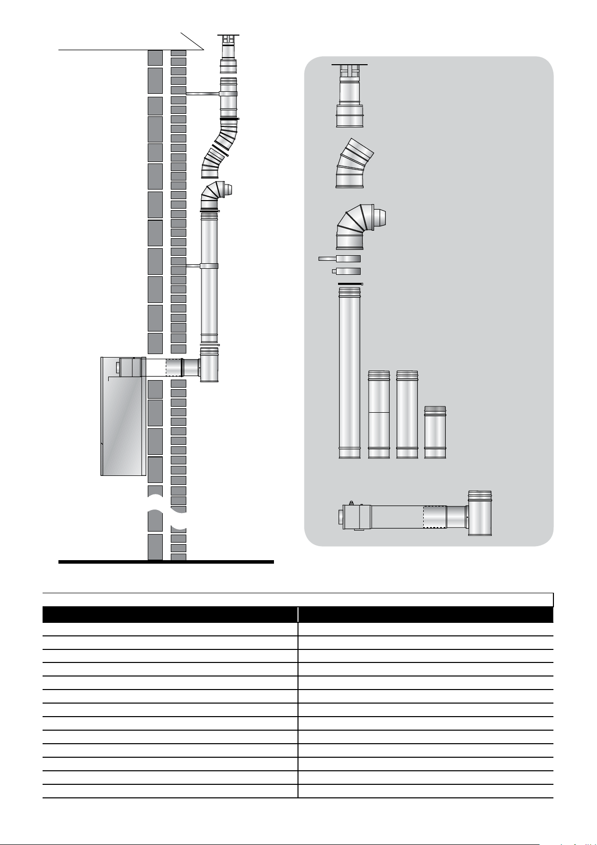
Vertical terminal kit
45° elbow kit
High level terminal kit
Extended wall bracket
Wall bracket
Locking band
Extension kits
Starter kit
Figure 9-13: External balanced ue (green system)
Table 9-14: Green system components - product codes
Item 12/16 and 16/21 models
Standard starter kit (stainless steel) GK90B
Short starter kit (stainless steel) GK90SB
150 mm extension GX150/90B
250 mm extension GX250/90B
450 mm extension GX450/90B
950 mm extension GX950/90B
195 - 270 mm adjustable extension GXA250/90B
45° elbow GE45/90B
Straight terminal GTL90B
High level 90° terminal GTH90B
Vertical terminal GTV90B
Wall bracket - standard GWB90B
Wall bracket - extended GEB90B
Section 9: Flue System and Air SupplyPage 34
Page 35
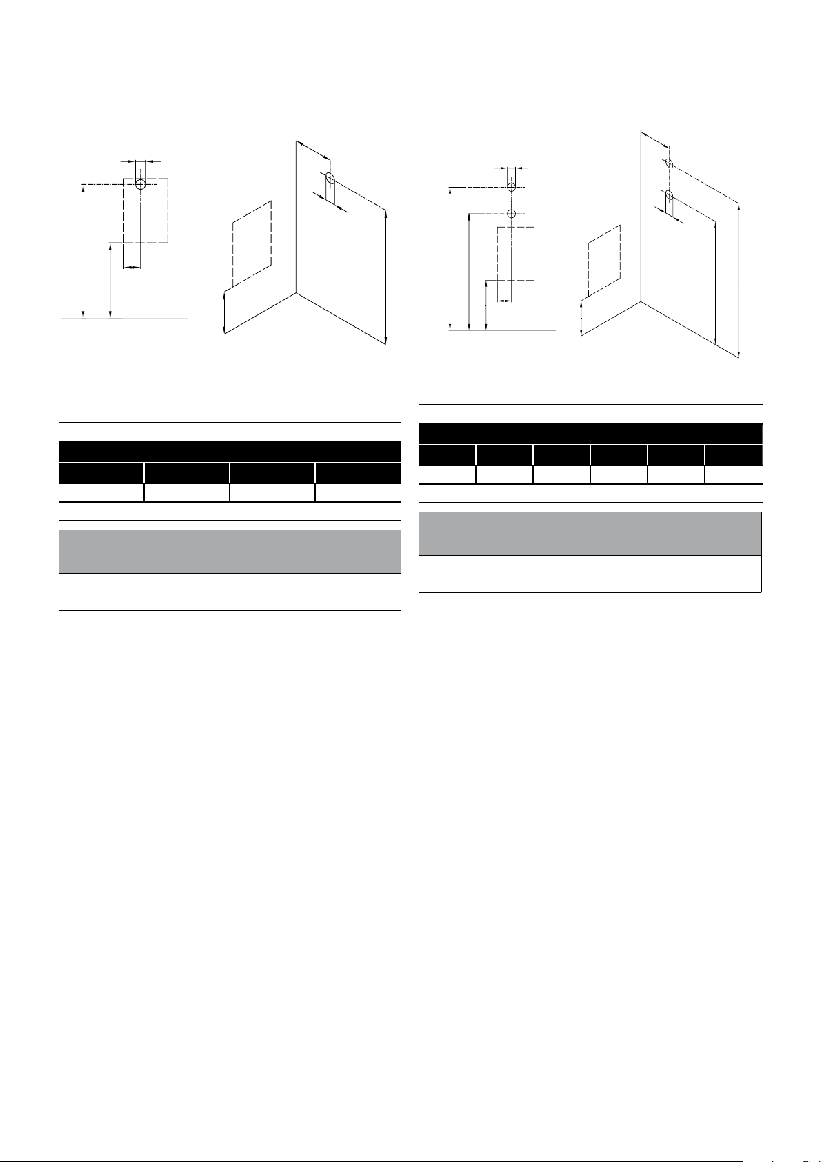
9.5 PREPARE THE WALL
B
9.5.1 LOW LEVEL BALANCED FLUE
If the boiler is to be used with a low level balanced ue (Yellow
system) make the hole in the wall for the ue as shown in Figure
9-15.
A
9.5.2 HIGH LEVEL AND VERTICAL BALANCED
FLUE
If the boiler is to be used with the high level balanced ue (White
system) make the hole in the wall as shown in Figure 9-17.
B
A
A
C
D
H
H
Rear flue Side flue
Figure 9-15: Flue hole dimensions and position for low level
system
Table 9-16: Low level balanced ue hole cutting dimensions
Dimension (mm)
A (dia.) B C D
127 110 H + 755* 220
* H is the height from the oor to the underside of boiler casing
! NOTE !
Dimension A given in Figure 9-11 includes an extra 10 mm
over the size of the terminal to provide clearance for tting.
A
D
C
C
E
H
H
Rear flue Side flue
D
C
Figure 9-17: Flue hole dimensions and position for high level
system
Table 9-18: High level balanced ue hole cutting dimensions
Dimension (mm)
A (dia.) B C min D min D ma x E
175 110 TBC TBC TBC 220
* Dimension C for starter section and elbow/terminal only
! NOTE !
Dimension A given in Figure 9-12 includes an extra 10 mm
over the size of the terminal to provide clearance for tting.
Fitting instructions for the high level balanced ue and vertical
balanced ue are supplied with the ue kits.
Adjustable extensions
The adjustable extensions are telescopic.
The wall terminal section is adjustable and is suitable for a wall
thickness of 215 mm to 450 mm.
Simply adjust to the required length using a twisting motion. The
outer pipes must overlap by a minimum of 25 mm.
Section 9: Flue System and Air Supply Page 35
Page 36

9.6 FLUE CLEARANCES
Figure 9-19: Flue clearances
Section 9: Flue System and Air SupplyPage 36
Page 37
Table 9-20: Flue clearances
Ref Location of outlet
A
Directly below an opening, air brick opening, opening window, etc.
B
Horizontally to an opening, air brick opening, opening window, etc.
C
Below a gutter, eaves or balcony with protection
D
Below a gutter, eaves or balcony without protection
E
From vertical sanitary pipework
F
From an internal or external corner
G
Above ground or balcony level
H
From a surface or boundary facing the terminal
J
From a terminal facing the terminal
K
Vertically from a terminal on the same wall
L
Horizontally from a terminal on the same wall
M
Above the highest point of an intersection with the roof
N
From a vertical structure to the side of the terminal
O
Above a vertical structure less than 750 mm from the side of the terminal
P
From a ridge terminal to a vertical structure on the roof
Q
Above or to the side of any opening on a at or sloping roof
R
Below any opening on a sloping roof
S
From oil storage tank (Class 1)
*
A heat shield at least 750 mm wide must be tted to provide protection of combustible material.
**
Clearances required by BS 5410-1:2014 to alleviate the effect of plume nuisance. If a risk assessment shows that there will be no impact from pluming,
then the ‘pressure jet’ gure could apply - seek conrmation from Local Authority Building Control.
Seek guidance from OFTEC Book 3 (Oil Storage and Supply).
***
Minimum distance (mm)
Pressure jet Condensing
600 1,000 **
600 1,000 **
75 * 1,000 **
600 1,000 **
300
300
300
600 2,500 **
1,200
1,500
750
600
750
600
1,500
300
1,000
1,800 ***
NOTES
1. Appliances burning class D fuel have additional restrictions. Refer to BS 5410-1:2014.
2. Vertical structure in N, O and P includes tank or lift rooms, parapets, dormers, etc.
3. Terminating positions A to L are only permitted for appliances that have been approved for low level ue discharge when tested in accordance with BS EN 303-1, OFS A100 or OFS
A101.
4. Terminating positions should be at least 1.8 metres from an oil storage tank (Class 1) unless a wall with at least 30 minutes re resistance and extending 300 mm higher and wider than
the tank is provided between the tank and the terminating position.
5. Where a ue is terminated less than 600 mm away from a projection above it and the projection consists of plastics or has a combustible or painted surface, then a heat shield of at least
750 mm wide should be tted to protect these surfaces.
6. If the lowest part of the terminal is less than 2 metres above the ground, balcony, at roof or other place to which any person has access, the terminal should be protected by a guard.
7. Notwithstanding the dimensions given above, a terminal should not be sited closer than 300 mm to combustible material. In the case of a thatched roof, double this separation distance
should be provided. It is also advisable to treat the thatch with a re retardant material and close wire in the immediate vicinity of the ue.
8. A ue or chimney should not pass through the roof within the shaded area delineated by dimensions Q and R.
9. Where protection is provided for plastics components, such as guttering, this should be to the standard specied by the manufacturer of the plastics components.
10. Terminals must not be sited under car ports.
11. Terminals at low levels (terminals under 2.1 metres) have more restrictive recommendations and should not be positioned near public footways, frequently used access routes, car
parking spaces less than 2.5 metres from the terminal or patio’s (hard surface area).
Further guidance can be obtained from BS 5410-1:2014, OFTEC Book 4 (Installation) and Approved Document J.
Grant UK ue products are fully compliant with the CE (Communauté Européenne/European Community) standards having undergone rigorous product testing.
Section 9: Flue System and Air Supply Page 37
Page 38
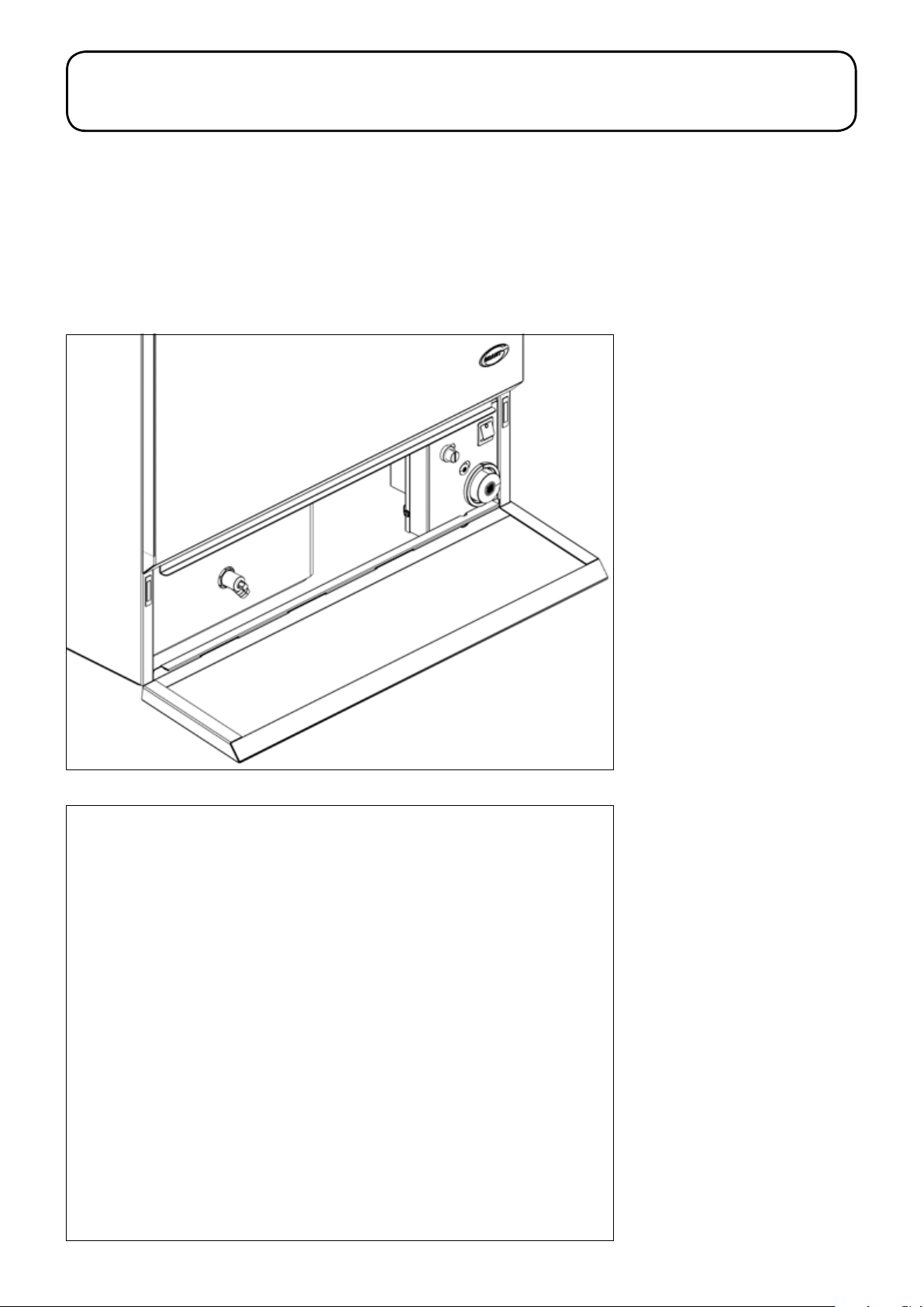
10 COMMISSIONING
To ensure safe and efcient operation, it is essential that a Grant
Eco Wall Hung boiler is commissioned as detailed in the following
procedure.
To access the controls, open the lower front panel by pulling it
down as shown in Figure 10-1.
The controls are shown in Figure10-2.
To access the remainder of the boiler, remove the upper front
panel. To do this, hold the lower edge of the panel and pull it
sharply outwards to disengage the retaining clips and lift off from
the boiler.
Figure 10-1: Boiler lower front panel in down position
Figure 10-2: Boiler controls
Section 10: CommissioningPage 38
Page 39
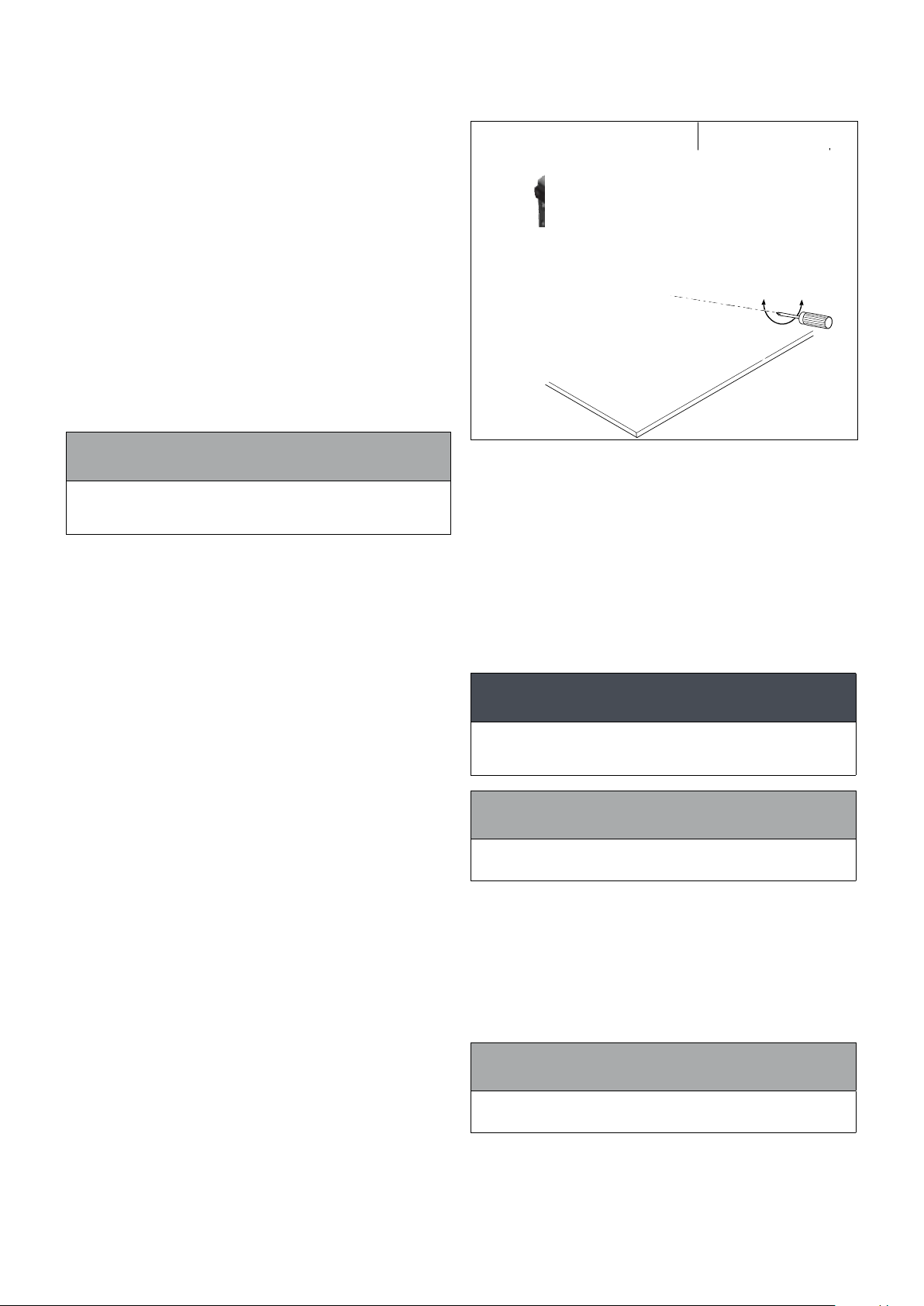
10.1 BEFORE SWITCHING ON
+––+
222
1. Ensure the boiler is isolated from the electrical supply and
the boiler On/Off switch is set to OFF.
2. Check that the high limit thermostat bulb and boiler
thermostat bulb are correctly located in their respective
pockets. Check condition of both thermostat capillaries.
Ensure they are not damaged, broken, kinked or crushed.
3. Remove the nuts and washers securing the front cleaning
door. Withdraw the door – take care as it is heavy!
4. Check that the turbulators are in position and that the ends
are vertical.
5. Check that the bafes are in position. Refer to Figure 11-1.
6. Ret cleaning door and check that it is tted correctly and
that a good seal is made.
7. Slacken of the hose clip and disconnect the exible air inlet
(snorkel) tube from the burner.
8. Unscrew the burner xing nut (located at the top of the
mounting ange), rotate the burner clockwise and remove the
burner from the boiler.
The burner has a slotted lug on the underside of the fan
housing. This allows the burner, when removed from the
boiler, to be hung on the bolt on the front of the combustion
door for checking/servicing.
10.2 BURNER SETTINGS
With the burner removed from the boiler:
1. Remove the burner head. Refer to Figure 10-3. Loosen the
two xing screws and remove the head from the burner.
! NOTE !
With two exible hoses connected to the burner, identify
(mark if necessary) which is the inlet and return if they are
to be disconnected.
9. Check/adjust the burner settings as described in Section
10.2.
10. Re-t the burner to the boiler and tighten the xing nut. DO
NOT OVERTIGHTEN!
11. Ensure that the condensing heat exchanger has been vented
via the automatic air vent.
12. Ensure the automatic air vent on the condensing heat
exchanger is open.
13. Check that all fuel line valves are open.
14. Connect a combined vent manifold and pressure gauge to
the pressure gauge connection port on the oil pump. Open
the vent screw on the vent manifold to vent the supply while
the pump is running.
15. Check that all system controls are calling for heat and turn
the boiler thermostat to maximum.
Figure 10-3: Removal of burner head
2. Check the nozzle is correct for the required boiler output.
Refer to Table 2-2 for the correct nozzle size and type for the
required boiler output.
3. If the nozzle needs to be replaced – remove the diffuser/
electrode assembly. Refer to Figure 10-4.
• Using a 3 mm Allen key, loosen the diffuser xing screw
on the electrode assembly.
• Lift the diffuser/electrode assembly up and off the nozzle
holder.
• Disconnect both ignition leads from the electrodes.
4. Use a 16mm spanner to remove /re-t the nozzle, whilst
holding the nozzle holder using another 16mm spanner.
! CAUTION !
The use of an ill-tting spanner will damage the nozzle
and could lead to an incorrect ame pattern and poor
combustion.
! NOTE !
Ensure that the nozzle is securely tightened so it does not
leak but DO NOT OVERTIGHTEN!
5. Re-t the diffuser/electrode assembly. Refer to Figure 10-4.
Re-connect ignition leads to electrodes.
Re-t the diffuser/electrode assembly onto the nozzle holder
lining up the xing screw with the with the recess in the
nozzle holder.
Ensure diffuser assemble is tted down hard onto the
shoulder on the nozzle holder.
Tighten the xing screw to secure the diffuser/electrode
assembly in place on the nozzle holder.
! NOTE !
Do not overtighten the xing screw as this may damage
the electrode insulator.
Section 10: Commissioning Page 39
6. Check/adjust the electrode setting. Refer to Figure 10-4.
Always check the electrode settings after replacing the
nozzle.
Page 40
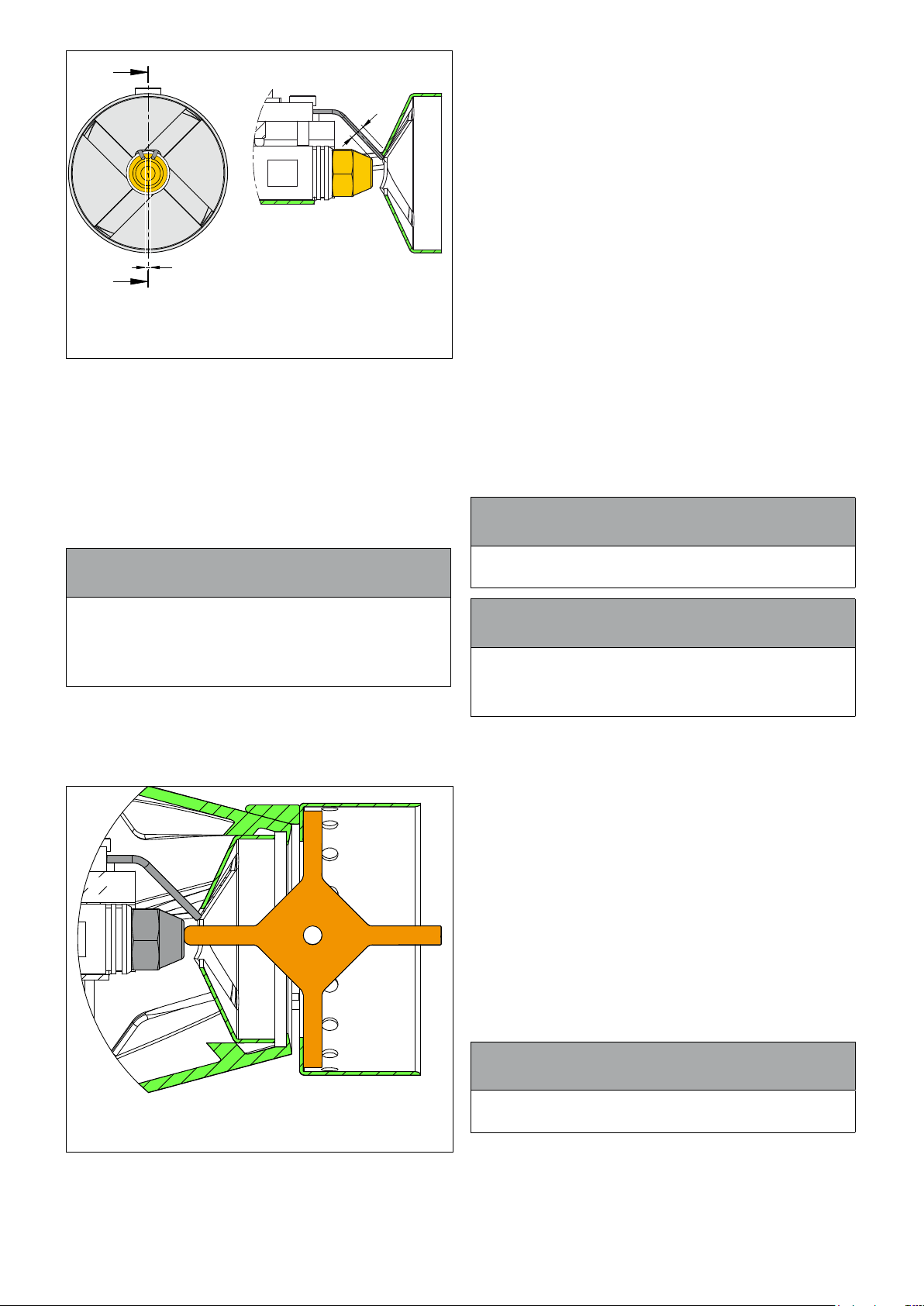
A
=
=
2
A
Check the distance beetwen
tips of electrodes.
Figure 10-4: Ignition electrode settings
7. Re-t the burner head. Refer to Figure 10-3.
• Locate the head xing screws in the countersunk slots in
the burner collar.
• Check/adjust the electrode setting. Refer to Figure 10-4.
• As the head will only t one way, rotate the head until
the two screws align with the slots.
• Tighten the two screws to secure the head in position on
the burner.
8. Check/adjust the diffuser position. Refer to Figure 10-4.
A-A
Check the distance beetwen
nozzle/electrodes and
diffuser/electrodes.
! NOTE !
• Position the gauge on the internal shoulder of the
burner head so the leg for the required output is pointing
towards the nozzle.
• Check that the gauge is at 90°to the internal shoulder of
the burner head and across the full diameter.
• If the diffuser setting is correct, the tip of the gauge leg
will just touch the front face of the nozzle, with the gauge
still in contact with the internal shoulder of the burner
head on BOTH sides. Refer to Figure 10-5.
• If the gauge leg is in contact with the nozzle face but
the gauge is NOT in contact with the internal shoulder
of the burner head on BOTH sides, the diffuser must be
‘opened’ (see below).
• If the gauge leg does not reach the nozzle with the
gauge is in contact with the internal shoulder of the
burner head on BOTH sides, the diffuser must be
‘closed’ (see below).
To adjust the diffuser position:
• If necessary, adjust the diffuser position by rotating the
adjustment screw, located on the front of the burner,
using a 4mm Allen key. Refer to Figure 10-3. Re-check
the diffuser setting using the gauge, as described above.
• To increase the distance between the nozzle face
and internal shoulder of the burner head (to open the
diffuser): rotate the adjusting screw clockwise.
• To decrease the distance between the nozzle face
and internal shoulder of the burner head (to close the
diffuser): rotate the adjusting screw anti-clockwise.
! NOTE !
One full rotation of the adjuster screw is approximately
1mm of diffuser (and nozzle) movement.
The diffuser position MUST be correctly set for the burner
to operate correctly.
The diffuser position is correctly set when the distance
between the internal shoulder of the burner head and the
face of the nozzle is as given in Table 2-2.
• Refer to Table 2-2 for the required distance (diffuser
setting) for the boiler output required. This is the
distance from the front face of the nozzle to the internal
shoulder of the burner head. Refer to Figure 10-5.
• Check the distance using the gauge supplied with the
burner.
! NOTE !
It is essential that the nal position of the diffuser is
checked, using the gauge provided with the boiler, and
the diffuser adjusted as necessary to achieve the required
position.
10.3 SWITCHING ON
1. Switch on the electricity supply.
2. Set the boiler On/Off switch to ON. A Neon on the switch
lights when it is in the ON position. The boiler will now light
automatically. Note that the neon lights when the boiler is
switched on, but does not necessarily indicate that the burner
is ring.
The burner should then re. Open the vent screw on the vent
manifold to vent the supply while the burner is ring.
3. The burner fan should start and the burner should light within
about 12 seconds. If the burner does not light and the ‘Lockout’ reset button on the burner lights, wait about 45 seconds
and press the reset button to restart the ignition process.
This procedure may have to be repeated several times during
rst lighting.
4. With the burner alight, check the fuel pressure. Refer to
Section 2.3 (burner settings).
5. Adjust the pressure if necessary.
Check the distance beetwen nozzle and
recirculation pipe.
Figure 10-5: Checking the diffuser position using the gauge
provided
• The three possible boiler output settings are stamped on
three of the legs of the gauge.
• To use the gauge: Identify the correct leg of the gauge
that matches the required boiler output.
! NOTE !
It is important that the oil pressure is correctly set.
6. Operate the boiler until it reaches normal operating
temperature. Check oil supply/return pipe for leaks, rectifying
where necessary.
7. Check the operation of the boiler thermostat. Ensure that by
turning it anticlockwise it switches the burner off.
8. With the burner alight, re-check the fuel pressure and readjust if necessary. Turn the boiler off, remove the pressure
Section 10: CommissioningPage 40
Page 41

gauge and replace the plug in the pump.
9. Ensure that there are no oil leaks.
10. On balanced ue installations – ensure the exible air inlet
tube and the exible air tube is connected to both the burner
air inlet and the ue system.
10.4 RUNNING THE BOILER
1. Re-light the boiler and allow it to run for at least 20 minutes.
2. Check the smoke number, if it is 0-1 then it is satisfactory.
3. Using a calibrated electronic ue gas analyser, set to the
correct fuel, check the %CO
in the ue gases.
2
! NOTE !
To allow the boiler to be commissioned and serviced
correctly a combustion test point is provided on the front
cleaning door. Both the %CO
carried out using this test point.
This test point is not suitable for measuring boiler
efciency or conventional ue draught.
When using the test point on the cleaning cover note that
the ue gas temperature reading will be higher than that
measured in the ue thus resulting in an inaccurate efciency
reading. To obtain an accurate ue gas temperature and
efciency, the reading can only be measured outside
through the low level ue terminal (or the test point on the
conventional ue started section when used).
For high level and vertical balanced ues, the reading may
be taken from the ue test point provided on the ue system.
Refer to Section 9.
For conventional ues, a test point is provided in the
conventional ue adaptor for ue draught and ue gas
temperature measurement. Refer to Section 9.
4. Set the %CO
required value given in Section 2.3 for the boiler concerned.
5. Adjust the burner air damper by rotating the adjuster knob
(see Figure 10-3) to achieve the required %CO
6. To increase the %CO
• Turn the knob anti-clockwise. This will close the burner
air damper and decrease the combustion air entering
the burner.
To decrease the %CO
• Turn the knob clockwise. This will open the burner air
damper and increase the combustion air entering the
burner.
7. When the %CO
smoke number if the damper has been moved. Under no
circumstances must the smoke number be above 1.
, as indicated on the ue gas analyser, to the
2
is set to the correct level, re-check the
2
and smoke test may all be
2
:
2
:
2
.
2
10.5 BALANCING THE SYSTEM
1. When the boiler has been adjusted and is running
satisfactorily, balance the central heating system by adjusting
the radiator lock shield valves.
Start with the radiator nearest the boiler and adjust the
valves to achieve the required temperature drop across each
radiator. If thermostatic radiator valves have been installed,
check the system by-pass.
2. Switch off the boiler.
10.6 COMPLETION
1. With the system hot, check again for leaks, rectifying where
necessary. Drain the system while it is hot to complete the
ushing process. Rell and vent (and pressurise if a sealed
system) the system.
2. A suitable central heating system inhibitor must be added to
protect the system against the effects of corrosion.
3. A suitable antifreeze should be used to prevent damage to
the boiler in areas where the electrical power failure can
occur in winter months.
4. Replace the upper and lower front panels on the boiler.
! NOTE !
After commissioning the boiler complete the
Commissioning Report in the front of this manual and the
OFTEC CD/11 commissioning report. Leave the top copy
with the User and retain the carbon copy.
If the boiler is to be left in service with the User, set the controls,
remote programmer and room thermostat to the User’s
requirements.
If the boiler is not to be handed over immediately, close the boiler
fuel supply valve and switch off the electricity supply.
! CAUTION !
If there is any possibility of the boiler being left during
frost conditions, then the boiler and system should be
drained. Alternatively, a suitable heating system antifreeze
should be used.
! NOTE !
For safer and efcient operation of the boiler it is essential
that the air damper is correctly set to give the required
%CO2 in the ue gases.
Section 10: Commissioning Page 41
Page 42

11 SERVICING
To ensure efcient operation of the boiler it is essential that a
Grant Eco Wall Hung boiler is serviced at regular intervals of no
longer than 12 months.
Servicing and replacement of parts must only be carried out by a
suitably qualied engineer.
! CAUTION !
Details of every service should be entered in the Service
Log, in the Boiler Handbook.
This information may be required to validate the Grant
extended guarantee.
! WARNING !
Before starting any work on the boiler, or fuel supply
please read the Health and Safety information given in
Section 14 of these instructions.
11.1 CHECKS BEFORE SERVICING
The following sequence of checks should be made before starting
any servicing work:
1. Check the ue terminal and ensure it is not blocked or
damaged.
2. Run the boiler and check the operation of its controls.
3. Ensure that all water system connections and ttings are
sound. Remake any joints and check the tightness of any
ttings that may be leaking.
4. Allow the boiler and system to cool down.
5. If the boiler is used on a sealed central heating system,
check the system pressure, check the operation of the
pressure relief valve and check the expansion vessel air
charge. Refer to Section 7.
6. Rell, vent and re-pressurise the system as necessary. Refer
to Section 7.
7. Check that any ventilation openings are of adequate free
area and are clear. Refer to Section 7.
8. Remove any sludge/water from the fuel tank by opening the
sludge valve at the lower end of the tank (if tted).
9. Ensure that all fuel system connections and ttings are
sound. Remake any joints and check the tightness of any
ttings that may be leaking.
10. With the fuel supply valve (at the oil tank) closed, clean/
replace the lter element and clean the lter bowl.
11.2 DISMANTLING PRIOR TO
SERVICING
The procedure for dismantling the boiler is as follows:
1. Remove the front panels from the boiler.
To remove the lower front panel: open by pulling top edge
down, slide panel to left or right and detach from the boiler.
To remove the upper front panel: hold the lower edge of the
panel and pull it sharply outwards to disengage the retaining
clips and lift off from the boiler.
2. On System models, carefully lift up and remove the
expansion vessel from the boiler. Place the vessel on the
front of the boiler. A clip is tted to clip it on to the top front
edge of the casing.
3. Slacken of the hose clip and disconnect the exible air inlet
(snorkel) tube from the burner.
4. Unscrew the burner xing nut (top of mounting ange) and
rotate the burner clockwise and withdraw the burner from the
boiler.
The burner has a slotted lug on the underside of the fan
housing. This allows the burner, when removed from the
boiler, to be hung on the bolt on the front of the combustion
door for checking/servicing.
5. If required, disconnect the exible oil line(s), using a suitable
container to prevent any oil spillage.
6. Check or replace the exible fuel supply hose(s), as follows:
• Braided exible fuel supply hoses (as supplied with the
boiler) should be replaced annually i.e. when the boiler
is serviced.
• Long-life hoses should be inspected annually. If in doubt
replaces the hose(s). In any event, these hoses must be
replaced every ve years.
! NOTE !
With a two-pipe oil supply there will be two exible hoses
connected to the burner. Identify (mark if necessary) which
is the inlet and return if they are to be disconnected.
! WARNING !
Before servicing, set the boiler On/Off switch to OFF,
isolate the electricity supply and close the fuel supply
valve.
The data label on the inside of the case side panel will indicate
the fuel used and the nozzle tted.
Section 11: ServicingPage 42
Page 43
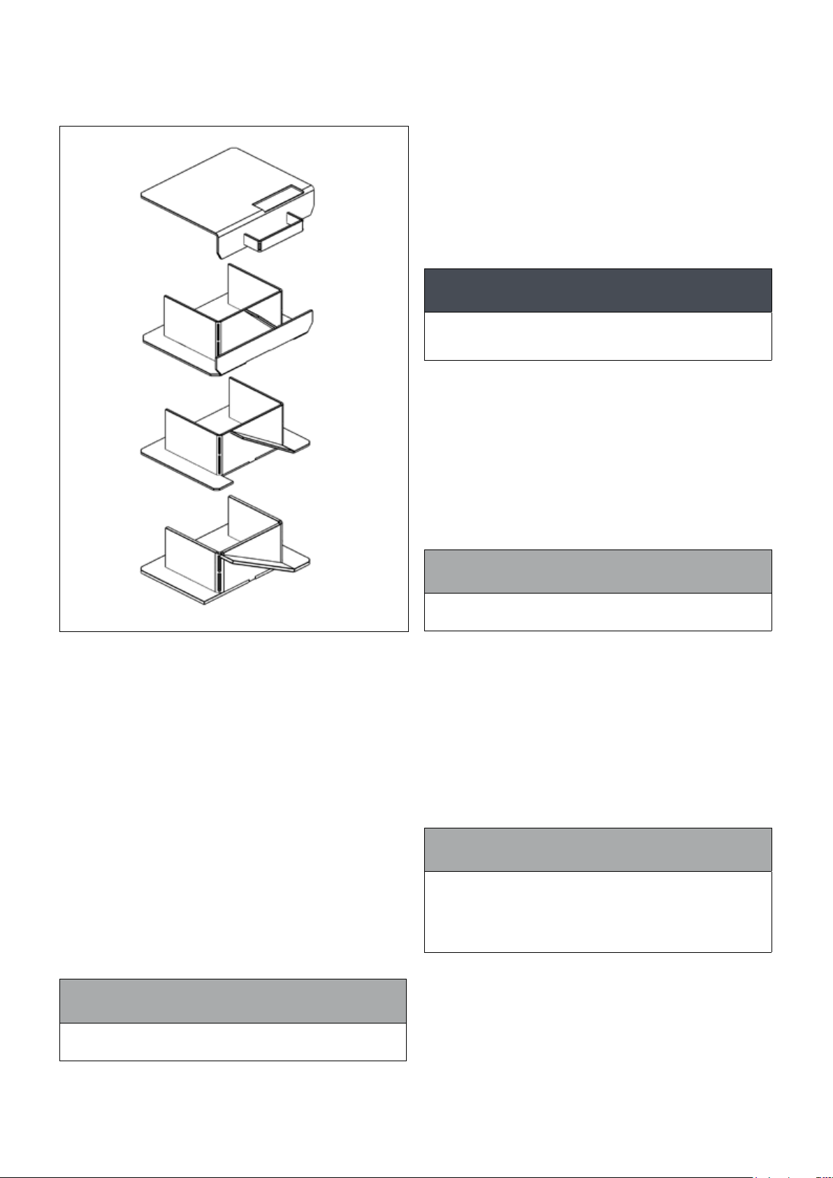
11.3 CLEANING THE BOILER
The procedure for cleaning the boiler is as follows:
1. Remove the nuts and washers securing the front cleaning
door and withdraw the door. Take care – it is heavy.
2. Remove the bafes as shown in Figure 11-1.
11.4 CLEANING THE BURNER
With the burner removed from the boiler:
1. Remove the burner head. Refer to Figure 10-3. Loosen the
two xing screws and remove the head from the burner.
2. Clean the burner head.
3. Remove the diffuser/electrode assembly. Refer to Figure 10-
2.
• Using a 3mm Allen key, loosen the diffuser xing screw
on the electrode assembly.
• Lift the diffuser/electrode assembly up and off the nozzle
holder.
• Disconnect both ignition leads from the electrodes.
4. Use a 16 mm spanner to remove/re-t the nozzle, whilst
holding the nozzle holder using another 16 mm spanner.
! CAUTION !
The use of an ill-tting spanner will damage the nozzle
and could lead to an incorrect ame pattern and poor
combustion.
5. Inspect the ignition electrodes – remove the electrode xing
screw and withdraw the electrode assembly. Wipe clean and
check for any cracks on the insulation. Replace if necessary.
6. Re-t the diffuser/electrode assembly. Refer to Figure 10-4.
• Re-connect ignition leads to electrodes.
• Re-t the diffuser/electrode assembly onto the nozzle
holder lining up the xing screw with the with the recess
in the nozzle holder.
• Ensure diffuser assemble is tted down hard onto the
shoulder on the nozzle holder.
• Tighten the xing screw to secure the diffuser/electrode
assembly in place on the nozzle holder.
Figure 11-1: Removing the bafes
3. Remove all deposits from the bafe plates and all the boiler
internal surfaces using a stiff brush and scraper if necessary.
4. Check the condition of the ue, clean as necessary.
5. Check the condition of the front cleaning door seal and
replace if necessary.
6. Replace the bafes, ensuring they are correctly tted. Refer
to Figure 11-1.
7. Pull out the spiral turbulators from the heat exchanger tubes.
8. Clean the turbulators using a stiff brush.
9. Test the heat exchanger condensate drain by pouring water
into one of the lower tubes and observe whether the water
discharges from the 22mm condensate outlet. Replace the
turbulators.
10. Replace the front cleaning door, ensuring the seal is in good
condition and secure it in position with the nuts and washers
previously removed. Tighten to form a seal.
11. Remove the condensate trap and check that it is not blocked
and is operating correctly, i.e. the oat is free to move. Clean
the trap and oat as required. Refer to Section 6.8.
12. Check that the boiler condensate outlet is unobstructed.
Clean if necessary.
! NOTE !
The condensate trap and condensate outlet must be
checked on every service and cleaned as necessary.
! NOTE !
Do not overtighten the xing screw as this may damage
the electrode insulator.
7. Check/adjust the electrode setting. Refer to Figure 10-4.
Always check the electrode settings after replacing the
nozzle.
8. Re-t the burner head. Refer to Figure 10-3.
• Locate the head xing screws in the countersunk slots in
the burner collar.
• Check/adjust the electrode setting. Refer to Figure 10-3.
• As the head will only t one way, rotate the head until
the two screws align with the slots.
• Tighten the two screws to secure the head in position on
the burner.
9. Adjust the diffuser position. Refer to Figure 10-5.
! NOTE !
The diffuser position MUST be correctly set for the burner
to operate correctly.
The diffuser position is correctly set when the distance
between the internal shoulder of the burner head and the
face of the nozzle is as given in Table 2-2.
• Refer to Table 2-2 for the required distance (diffuser
setting) for the boiler output required. This is the
distance from the front face of the nozzle to the internal
shoulder of the burner head. Refer to Figure 10-3.
• Check the distance using the gauge supplied with the
burner.
• The three possible boiler output settings are stamped on
three of the legs of the gauge.
• To use the gauge: Identify the correct leg of the gauge
that matches the required boiler output.
• Position the gauge on the internal shoulder of the
burner head so the leg for the required output is pointing
Section 11: Servicing Page 43
Page 44
towards the nozzle.
• Check that the gauge is at 90°to the internal shoulder of
the burner head and across the full diameter.
• If the diffuser setting is correct, the tip of the gauge leg
will just touch the front face of the nozzle, with the gauge
still in contact with the internal shoulder of the burner
head on BOTH sides.
• If the gauge leg is in contact with the nozzle face but
the gauge is NOT in contact with the internal shoulder
of the burner head on BOTH sides, the diffuser must be
‘opened’ (see below).
• If the gauge leg does not reach the nozzle with the
gauge is in contact with the internal shoulder of the
burner head on BOTH sides, the diffuser must be
‘closed’ (see below).
To adjust the diffuser position:
• If necessary, adjust the diffuser position by rotating the
adjustment screw, located on the front of the burner,
using a 4mm Allen key. Refer to Figure 10-3. Re-check
the diffuser setting using the gauge, as described above.
• To increase the distance between the nozzle face
and internal shoulder of the burner head (to open the
diffuser): rotate the adjusting screw clockwise.
• To decrease the distance between the nozzle face
and internal shoulder of the burner head (to close the
diffuser): rotate the adjusting screw anti-clockwise.
! NOTE !
One full rotation of the adjuster screw is approximately
1mm of diffuser (and nozzle) movement.
! NOTE !
It is essential that the nal position of the diffuser is
checked, using the gauge provided with the boiler, and
the diffuser adjusted as necessary to achieve the required
position.
10. Continue cleaning the other burner components as detailed
in Section 11.5
11.5 CLEANING THE BURNER
The procedure for cleaning the burner is:
Photocell
The photocell is a push-t in the front of the burner body.
1. Holding the body of the photocell and NOT the cable,
carefully pull the photocell out of the burner.
2. Clean the sensor end of the photocell.
3. Replace photocell back in the burner and check that it is fully
pushed in.
Burner air inlet
This is located on the right hand side of the burner. Refer to
Figure 10-3.
1. Using a 4mm Allen key, unscrew and remove the two screws
and remove the air inlet from the burner.
2. Check inside and remove any debris, leaves, hair, uff, etc.
from the air inlet housing and air damper.
Burner fan housing
This is located over the fan impeller. Refer to Figure 10-3.
With the burner air inlet already removed:
1. Using a 4mm Allen key, unscrew and remove the four screws
and remove the fan housing from the burner.
2. Check and clean the fan impeller and remove any debris,
leaves, hair, uff, etc.
3. Check/clean the fan housing.
4. Check the rubber seal around the fan housing. Replace if
damaged or missing.
5. Re-t the fan housing to the burner and secure with the four
screws.
6. Re-t the burner air inlet to the burner and secure with the
two screws.
Oil pump lter
This is located under the end cover on the oil pump. Refer to
Figure 10-3.
1. Using a 4mm Allen key, unscrew and remove the four cap
screws securing the pump end cover. Remove end cover
from pump.
2. Remove the lter and wash in kerosene.
3. Check the O-ring seal around the end cover. Replace if
damaged.
4. Ret the lter and end cover.
5. Re-t the four cap screws, tighten evenly, to secure the end
cover.
11.6 RECOMMISSIONING
! WARNING !
To ensure safe and efcient operation of the boiler it is
important that re-commissioning is carried out, especially
combustion checks (%CO2 level, ue gas temperature and
smoke number) after the boiler has been serviced. Refer to
the Commissioning instructions in Section 10.
Section 11: ServicingPage 44
Page 45
12 FAULT FINDING
12.1 BURNER FAULT FINDING CHARTS
12.1.1 BURNER FAILS TO START, NO FLAME, NO LOCK OUT
Symptoms Possible causes Actions
Motor fails to run No electrical supply to boiler ► Check ON/OFF switch is ON - mains neon is lit
▼ ▼
Lock-out light not lit Fuse has blown ► Check or replace fuse
▼
If fuse has blown - check reason for failure
Boiler thermostat not calling ► Adjust boiler thermostat to call for heat
Heating controls are not calling ► Adjust programmer and room thermostat to call
Overheat thermostat has operated ► Check and reset overheat thermostat if required
▼
If operated - check reason for operation
No power to burner ► Check for 230 volts at control box mains terminals
Control box faulty ► Replace faulty control box
12.1.2 BURNER FAILS TO START, NO FLAME, GOES TO LOCKOUT
Symptoms Possible causes Actions
Motor fails to run No power to burner motor ► Check for 230 volts at motor plug terminals
▼
Burner lockout Burner motor capacity faulty ► Check and replace if necessary
Burner motor faulty ► Replace burner motor
Burner motor stalled
▼
Seized oil pump ► Check and replace faulty oil pump
Section 12: Fault Finding Page 45
Page 46
12.1.3 BURNER STARTS, NO FLAME, GOES TO LOCKOUT
Symptoms Possible causes Actions
Motor runs Flame instability
▼ ▼
Burner pre-purges Carbon / soot on combustion head ► Clean blast tube
▼ ▼
Burner does not re No oil pressure ► Check pump drive coupling - replace if failed
▼
Burner lock-out Low oil pressure ► Check oil pump pressure is correct
▼
Excessive combustion air ► Adjust air damper setting
▼
Excessive ue draught (CF only) ► Rectify condition (is a draught stabiliser required?)
False light ► Check photocell is not sensing ambient light
No ignition spark ► Check HT lead connections are sound
Check ignition electrode gap is correct
Check for 230 volts at ignition transformer
Check transformer - replace if faulty
No oil at nozzle ► Check for sufcient fuel in tank
Check re valve has not tripped
Check all oil supply valves are open
Check oil line and pump is not air-locked
Check operation of solenoid valve
Check pump drive coupling - replace if failed
Check fuel pump - replace if seized
Restriction in oil supply ► Check lters, valves and oil lines and rectify
Fuel contamination (water in tank) ► Check tank, lters and oil line for water
12.1.4 BURNER FIRES, GOES TO LOCKOUT
Symptoms Possible causes Actions
Motor runs Flame instability
▼ ▼
Burner pre-purges Carbon / soot on combustion head ► Clean combustion head
▼ ▼
Burner res Fuel contamination (water in tank) ► Check tank, lters and oil line for water
▼
Burner lockout Low oil pressure ► Check oil pump pressure and adjust if necessary
▼
Excessive combustion air ► Adjust air damper setting
▼
Excessive ue draught (CF only) ► Rectify condition (is a draught stabiliser required?)
Photocell not sensing light ► Check photocell is clean and unobstructed
Photocell failed ► Replace faulty photocell
Defective nozzle ► Replace nozzle
Section 12: Fault FindingPage 46
Page 47
12.1.5 DELAYED IGNITION, BURNER STARTS VIOLENTLY
Symptoms Possible causes Actions
Burner pulsates on
start up
Burner starts violently Delayed ignition ► Check electrode settings
Excessive combustion air ► Recommission burner - adjust air setting
Low oil pressure ► Check and recommission burner
Partially blocked nozzle ► Replace nozzle
Fuel contamination (water in tank) ► Check tank, lters and oil line for water
Fan slipping on shaft ► Check and re-tighten
Pump coupling loose or worn ► Check and replace
Check electrodes for damage
Check HT lead connections are sound
Check HT leads for damage or arcing
12.1.6 BURNER CYCLES ON AND OFF
Symptoms Possible causes Actions
Burner ring Restriction in oil supply ► Check lters, valves and oil lines and rectify
▼
Burner stops ring Fuel contamination (water in tank) ► Check tank, lters and oil line for water
▼
Pre-purge starts Partially blocked nozzle ► Replace nozzle
▼
Burner res Vitiated combustion air (balanced ue only) ► Disconnect snorkel tube and check operation
▼ ▼
Burner stops ring Check ue terminal for obstructions and rectify
▼
Check ue system for leaks and rectify
Boiler thermostat hunting ► Replace faulty thermostat
Section 12: Fault Finding Page 47
Page 48
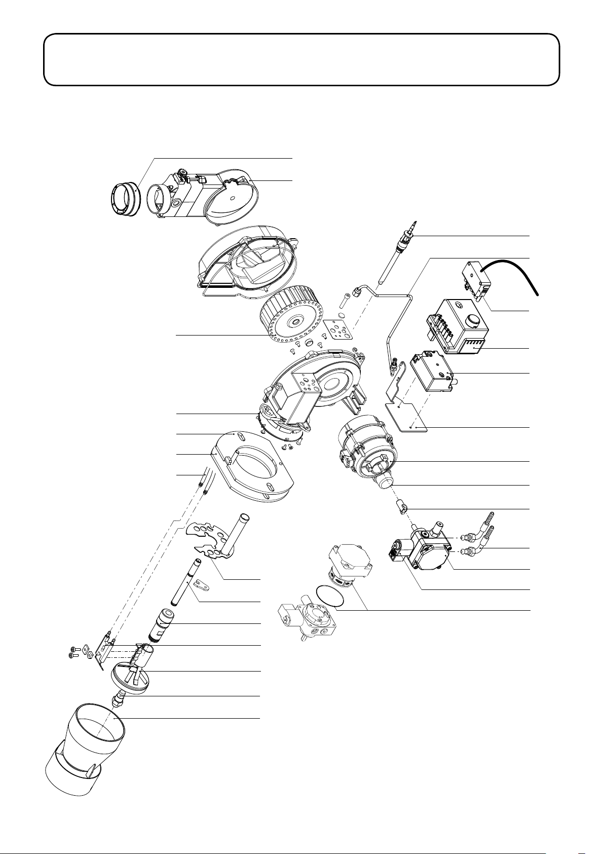
13 SPARE PARTS
This section gives exploded views of the Ecoam Max 1 low NOx yellow ame burners in the Grant Vortex Eco Wall Hung boilers, and
parts lists associated with them.
0170 0290
0270 0120
0140
0150
0110
01600250
0260
0180
0100
0130
0030 0090 00800300
0050
0010
0230
0020
0240
0210
0190
Figure 13-1: Ecoam Max 1 low NOx yellow ame burner exploded diagram - 15/21, 15/26, 26/36 and 36/46kW models
0220
0200 0280
Section 13: Spare PartsPage 48
Page 49
• Combustion head (16-21) 65327409 EBS65327409
• Combustion head (12-16) 65327408 EBS65327408
• Diffuser (16-21) 65327412 EBS65327412
• Diffuser (12-16) 65327411 EBS65327411
• Nozzle - 0.40/80°S - M1BS27/100
• Nozzle - 0.40/80°EH - M1BS27/50
• • Nozzle - 0.50/80°EH - M1BS27/46
• Nozzle - 0.60/80°EH - M1BS27/31
0030 • • Coupling 65322920 EBS65322920
0050 • • Hoses 65327402 EBS65327402
0020 • • Coil (Danfoss BFP T85) 65327293 EBS65327293
0010 • • Oil pump (Danfoss BFP11 R3 65322968 EBS65322968
Key No. 12-16 16-21 Description Ecoam product code Grant product code
0090 • • Capacitor (4 μF) 13011117 EBS13011117
0100 • • Ignition transformer 65323257 EBS65323257
0080 • • Motor 65326747 EBS65326747
0110 • • Control box with cables 65327403 EBS65327403
0130 • • Support 65327405 EBS65327405
0120 • • Photoresistor 65327404 EBS65327404
0170 • • Cover air inlet 65327407 EBS65327407
0150 • • Fan 65323826 EBS65323826
0160 • • O-ring 65321066 EBS65321066
0140 • • Plug and cable 65327406 EBS65327406
0180 • • Cables 65320934 EBS65320934
0200
0190 • • Electrodes 65327306 EBS65327306
0220
0210 • • Nozzle holder 65327410 EBS65327410
0250 • • Flange 65320975 EBS65320975
0240 • • Rod 65327414 EBS65327414
0230 • • Conveyor 65327413 EBS65327413
0270 • • Oil pipe 65327415 EBS65327415
0260 • • Gasket 65321089 EBS65321089
0280
0300 • • Set lter and seal 65325684 EBS65325684
0290 • • Ring 65320513 EBS65320513
Figure 13-2: Ecoam Max 1 low NOx burner parts list
Section 13: Spare Parts Page 49
Page 50
14 DECLARATION OF CONFORMITY
EC DECLARATION OF CONFORMITY
In accordance with BS EN ISO/IEC 17050-1:2004
We: Grant Engineering (UK) Limited
Of: Hopton House
Hopton Industrial Estate
Devizes
SN10 2EU
Telephone: +44 (0)1380 736920
Fax: +44 (0)1380 736991
Email: [email protected]
Website: www.grantuk.com
Declare that:
Equipment: Domestic oil boilers
Model Name/Number: Grant Vortex Eco Wall Hung 12-16 and 16-21
Indoor
Grant Vortex Eco Wall Hung System 12-16 and 16-21
Indoor
Note: All Grant system variants are supplied with glandless high efciency integrated circulators
In accordance with the following Directives:
2006/95/EEC Conforms with the safety objectives of the Low Voltage Directive and its amending directives.
2004/108/EC Conforms with the essential protection requirements of the Electromagnetic Compatibility
Directive and its amending directives.
92/42/EC Conforms with the requirements of the Boiler Efciency Directive.
2010/30/EU Conforms with the Labeling of Energy related products to EU (no) 811/2013
2009/125/EC Conforms with the Ecodesign of Energy related products to EU (no) 813/2013
I hereby declare that the equipment named above has been tested and found to comply with the relevant sections of the above
referenced specications. The unit complies with all essential requirements of the Directives.
Responsible Person: Neil Sawers
Position: Technical Manager
Signature:
Date: 23rd September 2016
Section 14: Declaration of ConformityPage 50
Page 51

15 HEALTH AND SAFETY INFORMATION
Under the Consumer Protection Act 1987 and Section 6 of the
Health & Safety at Work Act 1974, we are required to provide
information on substances hazardous to health (COSHH
Regulations 1988).
Adhesives, sealants and paints used in the manufacture of the
product are cured and present no known hazards when used in
the manner for which they are intended.
The following other materials are present in the product:
15.1 INSULATION MATERIALS
Material Types:
Ceramic bre board, mineral wool.
Description:
Rigid board, slabs, sleeves, gaskets, ropes.
Known Hazards:
May cause temporary irritation or rash to skin. High dust levels
may irritate eyes and upper respiratory system.
Precautions:
Avoid unnecessary or rough handling, or harsh abrasion of
boards. Normal handling and use of material should not produce
high dust levels.
Avoid inhalation, and contact with skin and eyes.
After handling always follow normal good hygiene practices.
Protection:
Use disposable gloves, face mask and eye protection.
First Aid:
Eyes - If irritation occurs, wash eyes with copious amounts of
water.
If symptoms persist, seek immediate medical advice.
Skin
If irritation occurs, wash under running water before washing with
soap and water.
Inhalation
Remove to fresh air, drink water to clear throat and blow nose to
remove dust/bres.
Ingestion
Drink plenty of water.
15.3 KEROSENE AND GAS OIL FUELS
(MINERAL OILS)
Known Hazards:
The effect of mineral oils on the skin vary according to the
duration of exposure and the type of oil.
The lighter fractions remove the protective grease naturally
present on the skin, leaving it dry, liable to crack and more prone
to damage by cuts, abrasions and irritant chemicals.
Skin rashes (Oil acne) most often on arms, but also on any part of
the body in contact with oil or oily clothing.
Contact with fuel oils can cause dermatitis.
Precautions:
Avoid as far as possible any skin contact with mineral oil or with
clothing contaminated with mineral oil.
The use of a lanolin-based barrier cream is recommended, in
conjunction with regular washing with soap and rinsing with water
to ensure all oil is removed from the skin.
Take care to prevent clothing, especially underwear, from
becoming contaminated with oil.
Do not put oily rags or tools in pockets, especially trouser pockets.
Have rst-aid treatment at once for an injury, however slight.
Do not inhale any vapours from mineral oils.
15.2 SEALANT AND ADHESIVE
Material Types:
Silicone elastomer.
Description:
Sealant and adhesive.
Known Hazards:
Irritation to eyes.
Precautions:
Avoid inhalation of vapour, contact with eyes and prolonged or
repeated contact with skin.
After handling always follow normal good hygiene practices.
Protection:
Use eye protection. Rubber or plastic gloves should be worn
where repeated contact occurs and a face mask worn when
working in conned spaces.
First Aid:
Eyes
Flush eyes with water for 15 minutes. Seek immediate medical
attention.
Skin
Wipe off and wash with soap and water.
Inhalation
Remove to fresh air.
Section 15: Health and Safety Information Page 51
Page 52
16 END OF LIFE INFORMATION
GENERAL
Grant oil boilers incorporate components manufactured from a variety of different materials. The majority of these materials can be
recycled whilst the smaller remainder cannot.
Materials that cannot be recycled must be disposed of according to local regulations using appropriate waste collection and/or disposal
services.
DISASSEMBLY
There is little risk to those involved in the disassembly of this product. Please refer to and follow the
Health and Safety Information given in the Installation & Servicing Instructions provided with the boiler.
For guidance on the disassembly of the boiler refer to the information given in the Servicing section of the Installation & Servicing
Instructions provided with the boiler.
RECYCLING
Many of the materials used in Grant oil boilers can be recycled, these are listed in the table below:
COMPONENT MATERIAL
Outer casing panels Mild steel (polyester powder coated)
Primary heat exchanger and bafes Mild steel
Secondary heat exchanger Stainless steel
Secondary heat exchanger spirals Aluminium alloy
Pipework Copper
Burner body/ange Aluminium alloy
Burner oil pump Aluminium alloy/steel
Riello oil burner cover Plastic
Electrical wiring Copper/plastic
Thermostats Copper/plastic
Printed Circuit boards Copper/plastic
DISPOSAL
All materials other than those listed above must be disposed of responsibly as general waste.
Neil Sawers
Technical Manager
Grant Oil Boiler Fiche V1.9 21/02/2017
Section 16: End of Life InformationPage 52
Page 53
17 PRODUCT FICHE
Product che concerning the
COMMISSION DELEGATED REGULATIONS
(EU) No 811/2013 of 18 February 2013
(EU) No 813/2013 of 2 August 2013
Vortex Pro Utility Symbols Unit
12-16
16-21
System 12-16
Condensing boiler Yes Yes Yes Yes
Low temperature boiler No No No No
B1 boiler No No No No
Combination heater No No No No
Rated heat output Prated KW 16 21 16 21
Useful heat output
At rated heat output and high temperature
regime
At 30% of rated heat output and low
temperature regime
P
4
P
1
KW 16 21 16 21
KW 4.8 6.3 4.8 6.3
Auxiliary electricity consumption
At full load elmax kW 0.164 0.150 0.164 0.150
At part load elmin kW 0.062 0.07 0.062 0.07
In standby mode P
SB
kW 0 0 0 0
Useful efciency
Seasonal space heating energy efciency ƞs % 90.13 90.52 90.13 90.52
At rated heat output and high temperature
regime
At 30% of rated heat output and low
temperature regime
ƞ
4
ƞ
1
% 93.1 90.8 93.1 90.8
% 96.7 96.9 96.7 96.9
Other items
Standby heat loss P
Ignition burner power consumption P
Annual energy consumption Q
Sound power level indoors L
Emissions of nitrogen oxides NO
stby
ign
HE
WA
X
kW 0.207 0.236 0.207 0.236
kW 0 0 0 0
kWh - - - -
dB 51.2 51.7 51.2 51.7
mg/ kWh <120 <120 <120 <120
Emission class 2 2 2 2
Daily fuel consumption Q
fuel
kWh - - - -
Annual fuel consumption AFC GJ - - - -
System 16-21
Section 17: Product Fiche Page 53
Page 54

18 GUARANTEE
You are now the proud owner of a Grant Vortex condensing boiler
from Grant Engineering (UK) Limited which has been designed to
give years of reliable, trouble free operation.
Grant Engineering (UK) Limited guarantees the manufacture of
the boiler including all electrical and mechanical components for a
period of twelve months from the date of installation
4
, provided
that the boiler has been installed in full accordance with the
installation and servicing instructions issued.
This will be extended to a total period of two years if the boiler is
registered with Grant Engineering (UK) Limited within thirty days
of installation and it is serviced at twelve month intervals
3
. See
main Terms and Conditions below.
If the boiler is installed as part of a VortexAir (hybrid) installation,
the guarantee for the boiler will start from its original date of
installation and NOT from the date of installation of the heat pump
(if installed on different dates).
Registering the product with Grant Engineering (UK) Limited
Please register your Grant Vortex condensing boiler with Grant
Engineering UK Limited within thirty days of installation. To do
so visit:
www.grantuk.com/support/product-registration
You can register your boiler for a further twelve months
guarantee (giving two years from the date of installation
4
). This
does not affect your statutory rights1.
If a fault or defect occurs within the manufacturer’s
guarantee period
If your boiler should fail within the guarantee period, you must
contact Grant Engineering (UK) Limited who will arrange for the
repair under the terms of the guarantee, providing that the boiler
has been correctly installed, commissioned and serviced (if the
appliance has been installed for more than twelve months) by a
competent person and the fault is not due to tampering, running
out of oil, oil contamination, debris, system water contamination,
misuse, trapped air or the failure of any external components
not supplied by Grant Engineering (UK) Limited, e.g. re valve,
motorised valve, etc.
This two year guarantee only applies if the boiler is
registered with Grant Engineering (UK) Limited within thirty
days of installation
4
and is serviced after twelve months3.
In the rst instance
Contact your installer or commissioning engineer to ensure
that the fault does not lie with the system components or any
incorrect setting of the system controls that falls outside of the
manufacturer’s guarantee otherwise a service charge could result.
Grant Engineering (UK) Limited will not be liable for any charges
arising from this process.
If a fault covered by the manufacturer’s guarantee is found
Ask your installer to contact Grant Engineering (UK) Limited
Service Department on +44 (0)1380 736920 who will arrange for
a competent service engineer to rectify the fault.
Remember - before you contact Grant Engineering (UK)
Limited
• Ensure the boiler has been installed, commissioned and
serviced by a competent person in accordance with the
installation and servicing instructions.
• Ensure there is oil to supply the burner.
• Ensure the problem is not being caused by the heating
system or its controls. Consult the boiler handbook for
guidance.
Free of charge repairs
During the two year guarantee period no charge for parts or
labour will be made provided that the boiler has been installed and
commissioned correctly in accordance with the manufacturer’s
installation and servicing instructions, it was registered with Grant
Engineering (UK) Limited within thirty days of installation
4
and,
for boilers over twelve months old, details of annual service is
available3.
The following documents must be made available to Grant
Engineering (UK) Limited on request:
• Proof of purchase
• CD10 Installation Completion Form (or equivalent document)
• CD11 Commissioning Report Form (or equivalent document)
• Service documents (CD11 or equivalent document)
Chargeable repairs
A charge may be made (if necessary following testing of parts)
if the breakdown is due to any fault(s) caused by the plumbing
or heating system, e.g. contamination of parts due to system
contamination, sludge, scale, debris or trapped air. Refer to
‘Extent of manufacturer’s guarantee’.
Extent of manufacturer’s guarantee
The manufacturer’s guarantee does NOT cover the following:
• If the boiler has been installed for over two years.
• If the boiler has not been installed, commissioned, or
serviced by a competent person in accordance with the
installation and servicing instructions.
• Instances where the serial number has been removed or
made illegible.
• Fault(s) due to accidental damage, tampering, unauthorised
adjustment, neglect, misuse or operating the boiler contrary
to the manufacturer’s installation and servicing instructions.
• Damage due to external causes such as bad weather
conditions (ood, storms, lightning, frost, snow, or ice), re,
explosion, accident or theft.
• Fault(s) due to incorrectly sized expansion vessel(s),
incorrect vessel charge pressure or inadequate expansion on
the system.
• Fault(s) caused by external electrics and external
components not supplied by Grant Engineering (UK) Limited.
• Problems caused by lack of oil or faults with the oil storage
and supply system.
• Fault(s) due to contamination of the oil storage and supply
system, e.g. water or debris.
• Bleeding or removing oil storage tank contamination or
blockages from oil lines.
• Problems due to the ue system being incorrectly tted or not
installed to meet installation requirements.
• Boiler servicing, de-scaling or ushing.
• Cleaning out condensate traps/discharge pipes or thawing
out frozen condensate pipework.
• Checking and replenishing system pressure.
• Oil supply pipelines, electrical cables and plugs, external
controls not supplied by Grant Engineering (UK) Limited.
• Heating system components, such as radiators, pipes,
ttings, pumps and valves not supplied by Grant Engineering
(UK) Limited.
• Instances where the oil boiler has been un-installed and re-
installed in another location.
• Use of spare parts not authorised by Grant Engineering (UK)
Limited.
• Consumable items including, but not limited to, oil nozzles, oil
hoses, gaskets and seals.
Section 18: GuaranteePage 54
Page 55

IMPORTANT
The nozzle and braided oil hose supplied with the boiler are only
covered for the period up to the time of the rst service (twelve
months). Both must be changed on the rst service and on every
annual service thereafter.
IMPORTANT
A suitable oil lter with a minimum 15µ ltration must be installed
in the oil supply line.
Do not wait until the fuel supply runs out before you re-order.
Sludge in the bottom of the tank may be drawn into the fuel lines.
It is recommended that the boiler is switched off when the new oil
supply is delivered and that the fuel is allowed to settle for an hour
before restarting the boiler.
Terms of manufacturer’s guarantee
• The Company shall mean Grant Engineering (UK) Limited.
• The boiler must be installed by a competent person and
in full accordance with the relevant Codes of Practice,
Regulations and Legislation in force at the time of installation.
• The boiler is guaranteed for two years from the date of
installation
4
, providing that every twelve months the annual
service has been completed3 and the boiler registered with
the Company within thirty days of installation. Any work
undertaken must be authorised by the Company and carried
out by a competent service engineer.
• This guarantee will be invalid if the boiler does not have an
annual (every twelve month) service and will then be limited
to twelve months from the date of installation
• The shell (heat exchanger) of the oil boiler is covered by a
ve year parts only guarantee from the date of installation
4
.
4
This is subject to the following:
• The boiler is operated correctly, in accordance with the
Installation and servicing instructions.
• Grant Engineering (UK) Limited strongly recommends
that a Grant Mag-One in-line magnetic lter/s (or
equivalent
5
) is tted in the heating system pipework. This
should be installed and regularly serviced in accordance
with the lter manufacturer’s instructions. We reserve
the right to ask for proof of installation – failure to
provide this may result in the guarantee becoming
invalid.
• Proof is provided that the system has been ushed or
chemically cleaned where appropriate (refer to BS 7593)
and that the required quantity of a suitable corrosion
inhibitor added.
• Proof of annual servicing (including the checking of any
expansion vessels and pressure relief valves) must be
provided if and when requested by the Company.
• This guarantee does not cover breakdowns caused by
incorrect installation, neglect, misuse, accident or failure to
operate the boiler in accordance with the manufacturer’s
installation and servicing instructions.
• The boiler is registered with the Company within thirty days
of installation. Failure to do so does not affect your statutory
1
rights
.
• The balance of the guarantee is transferable providing the
installation is serviced prior to the dwelling’s new owners
taking up residence. Grant Engineering (UK) Limited must be
informed of the new owner’s details.
• The Company will endeavour to provide prompt service in
the unlikely event of a problem occurring, but cannot be held
responsible for any consequences of delay however caused.
• This guarantee applies to Grant Engineering (UK) Limited
boilers purchased and installed on the UK mainland, Isle of
Wight, Channel Islands and Scottish Isles only
2
. Provision
of in-guarantee cover elsewhere in the UK is subject to
agreement with the Company.
• All claims under this guarantee must be made to the
Company prior to any work being undertaken. Invoices for
call out/repair work by any third party will not be accepted
unless previously authorised by the Company.
• Proof of purchase and date of installation, commissioning
and service documents must be provided on request.
• If a replacement boiler is supplied under the guarantee (due
to a manufacturing fault) the product guarantee continues
from the installation date of the original boiler and not from
the installation date of the replacement4.
• The oil boiler must be connected to a mains water supply
(installations utilising a private water supply are not covered
by this guarantee).
• Breakdown/failure due to lime scale will not be covered by
this guarantee.
• The replacement of a boiler under this guarantee does not
include any consequential costs, such as the removal or
replacement of worktops, kitchen units, etc.
• The boiler (excluding external modules) must not be sited in
a location where it may be subjected to frost.
Hard water advice (for Combi boilers only)
If you live in a hard water area, protection against scaling must
be given to the domestic hot water heat exchanger of your
combination boiler.
You should t an appropriate scale inhibitor or water softener as
any breakdown caused by water scaling is not covered by the
manufacturer’s guarantee. Ask your installer for advice.
Foot notes
1. Your statutory rights entitle you to a one year guarantee
period only.
2. The UK mainland consists of England, Scotland and
Wales only. Please note that for the purposes of this
denition, Northern Ireland, Isle of Man and Scilly Isles
are not considered part of the UK mainland.
3. We recommend that your oil boiler is serviced every twelve
.
months (even when the guarantee has expired) to prolong
the lifespan and ensure it is operating safely and efciently.
4. The guarantee period will commence from the date of
installation, unless the installation date is more than six
months from the date of purchase, in which case the
guarantee period will commence six months from the date of
purchase.
5. As measured by gauss. The MagOne magnetic lter has a
gauss measurement of 12,000.
Version 1.2 – February 2017
Section 18: Guarantee Page 55
Page 56

GRANT ENGINEERING (UK) LIMITED
Hopton House, Hopton Industrial Estate, Devizes, Wiltshire, SN10 2EU
Tel: +44 (0)1380 736920 Fax: +44 (0)1380 736991
Email: [email protected] www.grantuk.com
 Loading...