

Grant Vortex Eco Series, Vortex Eco 26/35, Vortex Eco 15/21, Vortex Eco 21/26 Installation And Servicing Instructions
Page 1

Grant Vortex Eco
External and System Floor Standing Condensing Oil Boiler Range
Installation and Servicing Instructions
UK | DOC 0081 | Rev 3.1 | June 2015
Page 2

Important Note
For use with Kerosene* only.
After installing the boiler leave these
instructions with the User.
This appliance is deemed a controlled
service and specific regional statutory
requirements may be applicable.
*Operation on Bio-fuel
All Grant Vortex Eco condensing boilers,
manufactured since May 2011, are
suitable for operation on both standard
kerosene (Class C2 to BS2869) and also
bio-kerosene – up to a 30% blend (B30K).
All burner settings and nozzle sizes (as
detailed in Section 2.3 of this manual) are
correct for both standard kerosene and
bio-kerosene (B30K).
In order to operate this boiler on biokerosene it will be necessary to take
the following actions:
• Use a bio-kerosene (B30K
compatible flexible oil line in place of
the oil line supplied with this boiler.
• Have your oil storage tank and oil
supply line (including all pipework,
sight gauges, filters, isolating valves,
fire valves, ed-aeration devices, etc.)
checked for their compatibility with
bio-kerosene (B30K).
Where necessary some, or all, of
these items may have to be replaced
with a bio-kerosene compatible
alternative.
• Check the suitability of the flue
system with Grant UK.
• Use only bio-kerosene (B30K) that
conforms to OPS24.
IMPORTANT
Under no circumstances should the boiler
be used with bio-kerosene without the
above actions being taken first.
Date:______________________________
Commissioning Engineer:_____________________________________________________
Tel. No:____________________________
Boiler model:_______________________ Boiler output:________________ kW
Fuel type: Kerosene / Bio-Kerosene
Nozzle size:________________________ Pump pressure:_____________________
Air setting:_________________________ Flue gas % CO2:____________________
Net flue gas temp:___________________ Smoke No:_________________________
System flushed: yes / no Corrosion inhibitor added: yes / no
Antifreeze added: yes / no
For Sealed systems only:
Expansion vessel size:______________________ litres
Expansion vessel charge pressure:___________ bar
Sealed system fill pressure (cold):____________ bar
Service Log
It is recommended that the boiler should be regularly serviced, at least once a year, and
the details entered in the Boiler Handbook by the service engineer.
Declaration of Conformity
We declare that the Grant VORTEX range of Oil Boilers equipped with Riello RDB
burners approved to EN 267: 1999 satisfy the requirements of the following European
Directives:
1. 89/336/EEC - Electromagnetic Compatibility Directive
Referred to the generic standards EN 55014: 1993, EN 50082: 1: 1992
2. 73/23/EEC - Electrical Equipment Safety Regulations Directive
Referred to the generic standard NO: 3260: The Electrical Equipment (Safety)
Regulations: 1994
3. 92/42/EEC - Hot Water Boiler Efficiency Directive
Referred to the generic standard The Boiler (Efficiency) (Amendment) Regulations
1994 (SI 1994/3083)
GRANT ENGINEERING (UK) LIMITED
Hopton House, Hopton Industrial Estate, Devizes
???????
Wiltshire SN10 2EU
Tel: +44 (0)1380 736920 Fax: +44 (0)1380 736991
Email: [email protected] www.grantuk.com
This manual is accurate at the date of printing but will be superseded and should be disregarded if specifications and/or appearances are
changed in the interests of continued product improvement.
All good sold are subject to our official Conditions of Sale, a copy of which may be obtained on application.
2
2
© Grant Engineering (UK) Limited 2015. No part of this manual may be reproduced by any means without prior written consent.
Page 3

Contents
1 Introduction 4
1.1 How a condensing boiler 4
works
1.2 Boiler description 4
1.3 Boiler components 5
2 Technical Data 6
2.1 Boiler technical data 6
2.2 Sealed system data - sealed 7
system models
2.3 Vortex boilers using Class 7
C2 kerosene
2.4 Flue gas analysis 7
2.5 Water connections 7
2.6 Boiler dimensions 8
3 Oil Storage and Supply 9
System
3.1 Fuel supply 9
3.2 Burner oil connection 11
4 Boiler Installation 13
Information
4.1 Introduction 13
4.2 Boiler location 13
4.3 Preparation for installation 13
4.4 Installing the boiler 14
4.5 Regulations compliance 14
4.6 Completion 14
4.7 Before you commission 14
4.8 Heating system design 15
considerations
4.9 Underfloor heating systems 15
4.10 Pipework materials 15
4.11 Sealed systems 15
4.12 Underfloor pipework 15
6 Condensate Disposal 17
6.1 General requirements 17
6.2 Connections 17
6.3 Pipework 17
6.4 External pipework 17
6.5 Condensate soakaway 17
6.6 Condensate trap 18
6.7 Condensate disposal 18
pipework
6.8 Inspection and cleaning of 18
trap
7 Sealed Systems 19
7.1 Sealed system installation 19
7.2 System models 20
7.3 Fill the sealed system 20
7.4 Pressure relief safety valve 20
7.5 Circulating pump 21
8 Electrical 23
8.1 Connecting the power 23
supply
8.2 Frost protection 23
8.3 Control system wiring 24
diagrams
8.4 Boiler control panel wiring 25
diagram
9 Flue and Air Supply 26
9.1 Air supply 27
9.2 Low level discharge flue 27
9.3 Horizontal system 27
9.4 Green system 28
9.5 Hybrid system 29
9.6 Coventional flue systems 29
10 Commissioning 30
10.1 Before switching on 30
10.2 Switching on 30
10.3 Running the boiler 31
10.4 Balancing the system 31
10.5 Completion 31
10.6 Air adjuster disc - 15/21 only 31
11 Boiler Servicing 32
11.1 Checking before servicing 32
11.2 Dismantling prior to servicing 32
11.3 Cleaning the boiler 34
11.4 Cleaning the burner 34
12 Fault finding 35
12.1 Boiler fault finding 35
12.2 Burner fault finding 36
12.3 Circulating pump fault 37
diagnosis
13 Spare Parts 38
13.1 Boiler parts list 38
13.2 Burner heads 38
13.3 Riello RDB2.2 burner 39
14 Health and Safety 41
Information
14.1 Insulation materials 41
14.2 Sealant materials 41
14.3 Kerosene and gas oil fuels 41
(mineral oils)
15 Recycling and disposal 42
16 Guarantee 43
5 Pipe Connections 16
5.1 Water connections 16
18 Notes 45
3
Page 4

1 Introduction
This manual is intended to guide
Installers who have completed the
Grant Wood Pellet Boiler Installer
training course on the installation,
commissioning and servicing of the
Grant Spira Condensing Wood Pellet
Boiler.
A separate manual is available to guide
users in the operation of the boiler.
The following special text formats are
used in this manual for the purposes
listed below:
WARNING
!
Warning of possible human injury
as a consequence of not following
the instructions in the “warning”.
CAUTION
!
Caution concerning likely damage
to equipment or tools as a
consequence of not following the
instructions in the “Caution”.
NOTE
!
Used for emphasis or information
not directly concerned with the
surrounding text but of importance
to the reader.
1.1 How a Condensing Boiler
Works
During the combustion process,
hydrogen and oxygen combine to
produce heat and water vapour. The
water vapour produced is in the form
of superheated steam in the heat
exchanger. This superheated steam
contains sensible heat (available heat)
and latent heat (heat locked up in the
flue gas). A conventional boiler cannot
recover any of the latent heat and
this energy is lost to the atmosphere
through the flue.
The Grant Vortex Eco condensing
boiler contains an extra heat exchanger
which is designed to recover the latent
heat normally lost by a conventional
boiler. It does this by cooling the flue
gases to below 90°C, thus extracting
more sensible heat and some of the
latent heat. This is achieved by cooling
4
the flue gases to their dew point
(approximately 55°C).
To ensure maximum efficiency, the
boiler return temperature should be
55°C or less, this will enable the latent
heat to be condensed out of the flue
gases.
• The boiler will achieve net thermal
efficiencies of 100%.
To achieve maximum performance
from the Grant Vortex Eco boiler, it is
recommended that the heating system
is designed so that a temperature
differential of 20°C between the flow
and return is maintained. The use of
modulating circulating pumps (now
widely available) and effective control
systems should be considered.
The Grant VORTEX Eco boiler will
however still operate at extremely
high efficiencies even when it is not
in condensing mode and therefore
is suitable for fitting to an existing
heating system without alteration to the
radiator sizes. The boiler is capable of a
maximum flow temperature of 75°C.
1.2 Boiler Description
Grant Vortex Eco External modules have
an insulated weatherproof enclosure
made of galvanised steel with a powder
coated finish, and are designed for
external installation, either against a wall
or free standing some distance away
from the property, as required.
The External modules are part of the
Grant range of automatic pressure jet
oil boilers which have been designed
for use with a fully pumped central
heating system with indirect domestic
hot water cylinder. They are not suitable
for use with either a direct cylinder or a
‘primatic’ cylinder or gravity hot water.
The boilers are suitable for use on
open vented or sealed central heating
systems.
All models are supplied with the control
panel and burner factory fitted.
The factory fitted low level discharge
flue system can be adjusted on site for
either rear, left hand or right hand flue
outlet position as required.
An external conventional flue (Green
system (Figure 9-2) is also available
from Grant UK. Refer to Section 9.2 for
further details.
A Hybrid flue (Green/Orange) system
(Figure 9-3) is also available which
allows the External module to utilise an
existing chimney stack. Refer to Section
9.3 for further details.
Where an existing chimney is to be
lined - Grant recommends the use
of the Grant ‘Orange’ flue system,
specifically designed for the Vortex
range of condensing boilers. Refer to
Section 9.3 for further details.
Where a rigid conventional flue is
required, Grant recommends the use
of the Grant ‘Green’ and ‘Orange’ flue
system components. As no flue adaptor
is supplied with the boiler it will be
necessary to purchase the correct Grant
Starter Elbow in order to connect this
system to the boiler. Refer to Section 9
for further details.
The ‘Green’ and ‘Orange’ system
components can be used to construct
a flue of maximum vertical height 19
metres.
NOTE
!
The flue system materials and
construction MUST be suitable
for use with oil-fired condensing
boilers. Failure to fit a suitable
conventional flue may invalidate the
guarantee on the boiler.
A horizontal system - see Figure
9-4, is also available up to 4 metres components available:
• Straight starter
• Extensions 150 mm, 250 mm, 450
mm and 950 mm
• Adjustable extension 195 to 270
mm
• 45° elbow
• Straight terminal
Page 5

Green system
Standard external high level/vertical
flue starter kit - components available:
• External starter kit, straight or
elbow
• Extensions 150 mm, 250 mm, 450
mm, 950 mm
• Adjustable extension 195 to 270
mm
• 45° elbow
• High level terminal
• Vertical terminal
1.3 Boiler Components
All burners are pre-set for use with
kerosene and are supplied ready to
connect to a single pipe fuel supply
system with a loose flexible fuel line and
3/8” to 1/4” BSP male adaptor supplied
with the boiler.
If required, an additional flexible fuel
line (600 mm) and 3/8” to 1/4” BSP
male adaptor are available to purchase
from Grant UK, for two-pipe oil supply
systems (product code: RBS35 and
RBS36).
The temperature of the water leaving
the boiler to heat the radiators and hot
water cylinder is user adjustable.
The boiler is fitted with an overheat
thermostat (which allows it to be used
on a sealed central heating system)
which will automatically switch off the
boiler if the heat exchanger exceeds a
pre-set temperature of 111°C ± 3°C.
The boiler control panel is fitted with
an ON/OFF switch, boiler thermostat
control knob and the manual reset
button for the overheat thermostat.
An optional indoor programmer is
available to purchase from Grant
UK which allows the User to set the
operating times for central heating and
hot water (product code: EPKIT).
To access the controls remove the
front panel by turning the handle at
the bottom and withdrawing the cover
forwards at the bottom.
Figure 1-1: Boiler controls for external modules
5
Page 6

2 Technical Data
2.1 Boiler Technical Data - Vortex Eco
Model Unit 15/21 21/26 26/35
Water content litre 13 13 19
gal 2.9 2.9 4.2
Weight (dry) *
External modules
kg 113 (ex ternal module)
136 ( external system)
113 (external module)
136 ( external system)
142 (external module)
152 ( external system)
lb 249 (ex ternal module)
300 ( external system)
Flow connection 22 mm 22 mm 22 mm
Return connection 22 mm 22 mm 22 mm
Min. flow rate (∆ T=10°C) l/h l/h 1 780 2 200 2 980
Min. flow rate (∆ T=20°C) l/h l/h 890 1 100 1 490
Condensate connection 22 mm (only connect plastic)
Flue diameter (conventional) 100 mm
Waterside resistance ∆T=10°C mbar 28.5
Waterside resistance ∆T=20°C mbar 10
Maximum static head m 28
Minimum circulating head m 1
Boiler thermostat range °C 65 to 75
Limit (safety) stat shut of f temp. °C 111 ± 3
Max. hearth temperature °C Less than 50
Electricity supply 230/240 V ~ 50 Hz fused at 5 Amp
Motor power Watts 90
Starting current Amps 4.2
Running current Amps 0.85
Oil connection ¼ BSP Male (on end of flexible fuel hose)
Conventional flue draught N/m² Minimum 8.7 - Maximum 37
in wg Minimum 0.035 - Maximum 0.15
Maximum operating pressure - sealed system bar 2.0
Maximum operating pressure - open system bar 2.0
Maximum operating pressure - pressure relief
valve
bar 2.5
249 (external module)
300 ( external system)
313 (external module)
335 ( external system)
* Weight includes burner but excludes flue.
6
Page 7

2.2 Sealed System Data - Sealed System Models
15/21, 21/26, 26/35
Heating system pressure (cold) Maximum 1.0 bar / Minimum 0.5 bar
Operating pressure of pressure relief valve 2.5 bar
Expansion vessel size (pre-charged at 1 bar) 12 litres
Max. heating system volume (including boiler)* 128 litres - approximately
Cold water mains connection 15 mm copper pipe
Pressure relief valve discharge connection 15 mm copper pipe
Circulating pump head 7 m
* Based on vessel charge and system cold fill pressure of 0.5 bar
2.3 Vortex Eco Boiler Using Class C2 Kerosene
Model
and
burner
type
15/21
Riello
RDB2.2
21/26
Riello
RDB2.2
26/35
Riello
RDB2.2
Notes
1 The data given above is approximate only.
2 The above setting may have to be adjusted on site for the correct operation of the burner.
3 Gas Oil is not suitable for use with the Grant Vortex Eco boiler range.
4 The net flue gas temperatures given above are ± 10%.
5 When commissioning the air damper must be adjusted to obtain the correct CO2 level.
6 * Factory settings: 15/21 - 18.1 kW, 21/26 - 22.7 kW, 26/35 - 30.8 kW.
7 The combustion door test point may be used for CO2 and smoke readings only. Do not use this test point for temperature or efficiency readings.
8 When setting the 15/21 to 15.1 kW output the burner air adjuster disc requires repositioning. Refer to Section 10.
When setting the 21/26 to 20.7kW or the 26/35 to 25.6 kW output the combustion head must be changed. Refer to Section 11.4.
9 The installer must amend the boiler data label if the output is changed.
Heat Output SEDBUK
2009
(kW) (Btu/h)
annual
efficiency
Nozzle Oil
press.
(bar)
Smoke
No.
Burner
head
type
Burner
head/disc
setting
Fuel
flow
rate
(kg/h)
Flue
gas
temp.
(°C)
(%)
15.1 51 500
* 18.1 61 750 0.55/80°EH 7.5 0 - 1 T1 Disc setting C 1.53 75 - 80 11 - 12
20.7 70 600 0.60/80°EH 8.5 0 - 1 T1 Disc setting C 1.78 80 - 85 11 - 12
20.7 70 600
* 22.7 77 500 0.65/80°EH 8.5 0 - 1 T2 Fixed 1.95 85 - 90 11 - 12
25.6 87 350 0.75/80°EH 8.0 0 - 1 T2 Fixed 2.19 90 - 95 11 - 12
25.6 87 350
* 30.8 105 100 0.85/80°EH 9.1 0 - 1 T3 Fixed 2.65 85 - 90 11 - 12
34.7 118 400 1.00/80°EH 8.0 0 - 1 T3 Fixed 2.93 90 - 95 11 - 12
91.9
91.7
91.4
0.50/80°EH 7.0 0 - 1 T1 Disc setting B 1.29 70 - 75 11 - 12
0.60/80°EH 8.5 0 - 1 T1 Fixed 1.78 85 - 90 11 - 12
0.75/80°EH 8.0 0 - 1 T2 Fixed 2.19 75 - 80 11 - 12
CO
(%)
²
2.4 Flue Gas Analysis
To allow the boiler to be commissioned and serviced, the boiler is supplied with a combustion test point on the front cleaning door.
When this test point is used please note the following:
• The test point is for CO2 and smoke readings only.
• The boiler efficiency and temperature must be taken from the flue test point on high level, vertical and conventional flue adaptors.
• Concentric low level flues do not contain a test point. The temperature and efficiency readings must be taken from the flue
terminal.
2.5 Water Connections
Boiler model Flow connection Return connection
Size Fitting Supplied Size Fitting Supplied
15/21 22mm pipe Tectite elbow in fittings kit 22mm pipe Compression fitted
21/26 22mm pipe Tectite elbow in fittings kit 22mm pipe Compression fitted
26/35 22mm pipe Tectite elbow in fittings kit 22mm pipe Compression fitted
7
Page 8

2.6 Boiler Dimensions
Figure 2-1: 15/21, 21/26 and 26/35 external module dimensions
8
Page 9

3 Oil Storage and Supply System
3.1 Fuel Supply
Fuel Storage
The tank should be positioned in
accordance with the recommendations
given in BS 5410-1:2014, which gives
details of filling, maintenance and
protection from fire.
A steel tank may be used and must be
constructed to BS 799-5:2010 and OFS
T200.
CAUTION
!
A galavanised tank must not be
used.
A plastic tank may be used and must
comply with OFS T100.
NOTE
!
Plastic tanks should be adequately
and uniformly supported on a
smooth level surface, across their
entire base area, that is, the area in
contact with the ground.
Fuel Pipes
Fuel supply pipes should be of copper
tubing with an external diameter of at
least 10 mm.
Galvanised pipe must not be used.
All pipe connections should preferably
use flared fittings. Soldered connections
must not be used on oil pipes.
A remote sensing fire valve must be
installed in the fuel supply line (outside)
where it enters the building, with the
sensing head located above the burner.
Recommendations are given in BS
5410-1:2014.
It is recommended that a good quality
metal bowl type fuel filter is fitted at the
tank and a secondary filter in the fuel
supply line adjacent to the boiler (15
µ for Kerosene) to protect the burner
pump and nozzle from contamination.
If the boiler operates on bio kerosene, a
compatible filter should be used.
A flexible fuel line, adaptor and ¼” BSP
isolation valve are supplied loose with
the boiler for the final connection to
the burner. If a two pipe system or
‘Tiger Loop’ type de-aerator is used, an
additional flexible fuel hose (900 mm)
and 3/8” to 1/4” BSP male adaptor are
available to purchase from Grant UK
(product codes: RBS35 and RBS36).
Metal braided flexible hoses should be
replaced annually when the boiler is
serviced. Long life flexible hoses should
be inspected annually and replaced at
least every 60 months.
Single pipe system (see Figure 3-1)
With the storage tank outlet above the
burner a single pipe system should be
used. The height of the tank above the
burner limits the length of pipe run from
the tank to the burner.
Two pipe system (see Figure 3-2)
With the storage tank outlet below the
burner, a two pipe system should be
used. The pipe runs should be as
shown in Figure 3-2. The return pipe
should be the same level in the tank
as the supply pipe, both being 75 to
100 mm above the base of the tank.
The pipe ends should be a sufficient
distance apart so as to prevent any
sediment disturbed by the return
entering the supply pipe.
Avoid the bottom of the tank being
more than 3.5 m below the burner.
A non-return valve should be fitted in
the supply pipe together with the filter
and fire valve. A non-return valve should
be fitted in the return pipe if the top of
the tank is above the burner.
To be used with a two-pipe system, the
burner must be fitted with an additional
flexible fuel pipe - a flexible fuel hose
(900 mm) and 3/8” to 1/4” BSP male
adaptor are available to purchase from
Grant UK (product codes: RBS35 and
RBS36).
The pump vacuum should not exceed
0.4 bar. Beyond this limit gas is
released from the oil.
For guidance on installation of top outlet
fuel tanks and suction oil supply sizing,
see OFTEC Technical Book 3. Available
from OFTEC.
CAUTION
!
Flexible hoses must NOT be used
outside the boiler case of Utility
models.
Figure 3-1: Single pipe system
As supplied the burner is suitable for a
single pipe system
9
Page 10

Figure 3-2: Two pipe system
Figure 3-3: De-aeration device system
10
Page 11

Tiger Loop system (See Figures 3-3 and 3-4)
When the storage tank outlet is below
the burner, an alternative to a two
pipe system can be achieved using a
‘Tiger Loop’ type oil de-aerator. This
effectively removes the air from the oil
supply on a single pipe lift.
The de-aerator is connected close
to the boiler as a two pipe system
(omitting the non-return valve) as shown
in Figure 3-3.
Refer to the manufacturers instructions
supplied with the de-aerator.
The de-aerator must be mounted
vertically. See Figure 3-3 and 3-4.
WARNING
!
To prevent any possibility of fuel
fumes entering the building, the
de-aerator must be fitted outside in
accordance with BS 5410-1:2014.
To be used with a de-aerator, the
burner must be fitted with an additional
flexible fuel hose (a flexible fuel hose
(900 mm) and 3/8” to 1/4” BSP male
adaptor are available to purchase from
Grant UK (product codes: RBS35 and
RBS36).
3.2 Burner Oil Connection
The burner fuel pump is supplied for
use with a single pipe fuel supply
system.
For use on a two pipe system, it is
necessary to fit the By-pass screw, as
shown in Figure 3-5, into the tapping in
the return port.
The By-pass screw is supplied in the
boiler accessory pack.
Remove the plastic burner cover
(secured by two screws).
For ease of access to the fuel pump, to
fit the by-pass screw and connect the
oil lines, the burner can be removed
from the boiler. To do this, unscrew the
single nut at the top of the burner (using
a 13 mm spanner) and withdraw the
burner from the boiler.
Remove and discard the blanking plug
from the return connection of the pump
and fit the By-pass screw using an
hexagonal key.
Connect the return oil flexible fuel pipe
to the pump.
Connect the 3/8” to 1/4” BSP adaptor to
the flexible fuel pipe.
Flexible fuel pipes and adaptors are
available to purchase from Grant UK.
The blanking plug supplied in the inlet
(suction) port may now be plastic and
will not provide an oil tight seal when
the pump is running.
Figure 3-5: Riello RDB pump
Item Description
1 Inlet (suction) port
2 Return port
3 By-pass screw
4 Pressure gauge port
5 Pressure adjustment
6 Vacuum gauge port
7 Solenoid
8 Nozzle outlet
Figure 3-4: Tiger loop de-aeration device
WARNING
!
Ensure that the supply from the tank
is connected to this port and that
the plastic plug is discarded.
11
Page 12

Main Burner Components
It may be necessary to remove
theburner from the boiler to
accessconnections in the fuel pump.
Disconnect the flexible air tube from the
burner.
Remove the single nut at the top of the
burner (using a 13 mm spanner) and
withdraw the burner from the boiler.
NOTE
!
Remove the factory fitted air inlet
spigot adaptor (item 6) in Figure 3-6
from the air intake on the top right
hand side of the burner and fit the
grey plastic air inlet grille in its
place.
Burner Connection
If a two pipe system is to be used refer
to Section 3.2.
Remove and discard the blanking
plug from the inlet (suction) port of the
pump. Refer to Figure 3-5.
Connect the elbow of the flexible fuel
pipe supplied with the boiler to the inlet
port.
Connect the other end of the flexible
fuel pipe to the rigid supply line using
the adaptor supplied. The supply enters
through one of the holes in the casing
plinth.
12
Figure 3-6: Riello RDB burner components
Item Description
1 Oil pump
2 Control box
3 Reset button with lock-out lamp
4 Flange with gasket (do not remove from boiler)
5 Air damper adjustment screw
6 Air supply tube connection (balanced flue)
7 Pump pressure adjustment screw
8 Pressure gauge connection
Page 13

4 Boiler Installation Information
4.1 Introduction
All models are supplied fully assembled
with the flue terminal guard supplied
loose inside the boiler.
4.2 Boiler location
1. The External module must stand
on a solid, level surface capable of
supporting the weight of the boiler
when full of water, e.g. a prepared
concrete standing, paving slabs
bedded down on sand/cement, or
similar.
2. The module can be installed
either against the building or ‘free
standing’ some distance away
from the building.
3. The module must be positioned
such that the required clearances
from the low level flue outlet, as
shown in Figure 9-4, are achieved.
4. Adequate clearance must be left
around the module for servicing.
In particular, a minimum clearance
of 600 mm above the module for
removal of the top panel and 600
mm at the opposite end to the flue
outlet for access to the burner.
Sufficient clearance is required
at the rear of the boiler to allow
the rear panel to be removed for
access to the condensate trap.
4.3 Preparation for Installation
1. Carefully remove the packaging
from the boiler and remove it from
the transit pallet.
2. Remove the case top panel (four
screws) and also the front and rear
panels, as required.
3. The flue may exit the boiler from
the left, right or rear of the casing.
Carefully press out the pre-cut
section on the side or rear casing
panel to provide the opening in
the required position for the flue to
pass through the casing.
Fit the cover panel (with the round
flue exit hole) over the square
flue opening in the casing. Fit the
circular rubber sealing grommet,
provided, into the circular hole in
the cover panel before fitting the
flue terminal section.
4. Slacken the wing nuts holding the
flue elbow and rotate the elbow to
the required direction for the flue to
exit the casing.
5. Push the end of the flue terminal
section (with the red seal) through
the sealing grommet in the casing
panel.
The terminal section has been
factory lubricated. Take care not
to dislodge or damage the red flue
seal.
6. Carefully insert the terminal into
the flue elbow until the bend of
the terminal contacts the outer
casing, then, pull the terminal
forward approximately 25 mm and
rotate the bend so that the outlet is
horizontal.
Rear exit - The flue must
discharge away from the building.
Side exit - The flue should
discharge towards the rear of
the casing to prevent flue gases
re-entering the boiler casing
through the air inlet vents on the
casing front door.
The flue terminal must be fitted
horizontally to prevent dripping
from the end of the terminal.
7. Tighten the wing nuts holding the
flue elbow and fit the stainless
steel flue guard using the two
screws provided.
8. he top panel of the casing has
been designed so that it may be
fitted to create a slight slope away
from the side positioned against
the wall. To tilt the top panel,
loosen the four top panel casing
screws, one at each corner and
push down on the side furthest
from the wall. Tighten the screws.
See Figure 4-1.
Figure 4-1: Standard low level flue
13
Page 14

4.4 Installing the Boiler
1. 1. If the boiler is to be fitted against
the wall, prepare the wall to accept
the heating system pipework. To
mark the wall for drilling, refer
to Section 2.6 for the positions
of the pipework openings in the
enclosure sides.
NOTE
!
Pipework should be insulated
where it passes through the wall
into the boiler enclosure.
If the boiler is to be installed ‘free
standing’ (i.e. away from a wall)
and the pipework run underground,
push out the ‘knock-outs’ to open
the required pipe openings in the
base of the boiler enclosure. Using
a sharp knife, cut through the
polystyrene in the base, around
the edge of the holes, to allow the
flow and return pipes to enter the
enclosure.
2. The electrical supply to the boiler
should be routed through the wall
in a suitable conduit, such that it
enters the boiler enclosure via one
of the unused pipework openings.
The cable can be routed to the
front of the boiler, for connection to
the boiler control panel, either over
the top or beneath the boiler heat
exchanger. Heat resistant PVC
cable, of at least 1.0 mm² cross
section should be used within the
boiler enclosure.
3. The oil supply line should be
installed up to the position of the
boiler. Refer to Section 3.1 for
details. The final connection into
the boiler enclosure can be made
with 10 mm soft copper, routed
along the base of the enclosure
(either between the enclosure and
wall or in front of the enclosure)
to enter through one of the holes
located in the bottom edge side
panel, at the front (burner) end.
4.5 Regulations Compliance
Installation of a Grant VORTEX Eco
boiler must be in accordance with the
following recommendations:
• Building Regulations for England
and Wales, and the Building
Standards for Scotland issued by
the Department of the Environment
and any local Byelaws which you
must check with the local authority
for the area.
• Model and local Water Undertaking
Byelaws.
• Applicable Control of Pollution
Regulations.
• The following OFTEC
requirements:
• OFS T100 Polythene oil
storage tanks for distillate
fuels.
• OFS T200 Fuel oil storage
tanks and tank bunds for use
with distillate fuels, lubrication
oils and waste oils.
Further information may be obtained
from the OFTEC Technical Book 3
(Installation requirements for oil storage
tanks) and OFTEC Technical Book 4
(Installation requirements for oil fired
boilers).
The installation should also be in
accordance with the latest edition of
the following British Standard Codes of
Practice:-
• BS 715 Metal flue pipes, fittings,
terminals and accessories.
• BS 799:5 Oil storage tanks.
• BS 1181 Clay flue linings and flue
terminals.
• BS EN 1856-1:2009 Chimneys.
Requirements for metal chimneys.
System chimney products.
• BS 5449 Forced circulation hot
water systems.
• BS 7593 Code of Practice for
treatment of water in heating
systems.
• BS 7671 Requirements for
electrical installations, IET Wiring
Regulations.
NOTE
!
Failure to install and commission
appliances correctly may invalidate
the boiler guarantee.
WARNING
!
Before starting any work on the
boiler, or fuel supply please read
the health and safety information
given in Section 14.
4.6 Completion
Please ensure that the OFTEC CD/10
installation completion report (provided
with the boiler) is completed in full.
Leave the top copy with the User.
Retain the carbon copy.
Ensure that the User Information pack
(supplied with the boiler) is handed over
to the Householder.
4.7 Before you Commission
To avoid the danger of dirt and foreign
matter entering the boiler the complete
heating system should be thoroughly
flushed out - before the boiler is
connected and then again after the
system has been heated and is still hot.
This is especially important where the
boiler is used on an old system.
For optimum performance after
installation, this boiler and its
associated heating system must
be flushed in accordance with the
guidelines given in BS 7593:2006
‘Treatment of water in domestic hot
water central heating systems’.
This must involve the use of a
proprietary cleaner, such as
BetzDearborn’s Sentinel X300 or X400,
or Fernox Restorer. Full instructions are
supplied with the products, but for more
details of BetzDearborn’s products,
view the website www.sentinelsolutions.net and for more details of
Fernox products view the website www.
fernox.com.
14
Page 15

For long term protection against
corrosion and scale, after flushing, it is
recommended that an inhibitor such as
Betzdearborn’s Sentinel X100 or Fernox
MB-1 is dosed in accordance with the
guidelines given in BS 7593:2006.
Failure to implement these
guidelines will invalidate the
guarantee.
NOTE
!
We recommend that both antifreeze
and corrosion inhibitor be used in
the primary water system.
4.8 Heating System Design
Considerations
To achieve the maximum efficiency
possible from the Grant VORTEX Eco
boiler, the heating system should be
designed to the following parameters:
Radiators:
• Flow temperature 70°C
• Return temperature 50°C
• Differential 20°C
Underfloor:
• Flow temperature 50°C
• Return temperature 40°C
• Differential 10°C
Size radiators with a mean water
temperature of 60°C.
Design system controls with
programmable room thermostats or
use weather compensating controls
to maintain return temperatures below
55°C.
The use of a pipe thermostat is
recommended to control the return
temperature when using weather
compensating controls.
Refer to Section 2.5 for the size and
type of the connections and Section 5
for the position of the connections.
4.9 Underfloor Heating
Systems
In underfloor systems it is essential
that the return temperature must be
maintained above 40°C to prevent
internal corrosion of the boiler water
jacket.
4.10 Pipework Materials
Grant boilers are compatible with both
copper and plastic pipe. Where plastic
pipe is used it must be of the oxygen
barrier type and be of the correct class
(to BS 7291-1: 2010) for the application
concerned.
WARNING
!
The first metre of pipework
connected to both the heating flow
and return connections of the boiler
must be made in copper on all types
of system - sealed or open-vented.
4.11 Sealed Systems
If plastic pipe is to be used, the installer
must check with the plastic pipe
manufacturer that the pipe to be used
is suitable for the temperature and
pressures concerned.
Plastic pipe must be Class S to BS
7291-1: 2010.
WARNING
!
The system must incorporate a low
pressure switch to shut off power to
the boiler if the system pressure
drops below 0.2 bar. A suitable low
pressure switch kit is available to
purchase from Grant UK (product
code: MPCBS63).
4.12 Underfloor Pipework
Plastic pipe may be used on Underfloor
systems where the plastic pipe is fitted
after the thermostatic mixing valve.
Copper tube must be used for at least
the first metre of flow and return primary
pipework between the boiler and the
underfloor mixing/blending valves.
NOTE
!
The boiler should not be allowed to
operate with return temperatures of
less than 40°C when the system is
up to operating temperature.
15
Page 16
5 Pipe Connections
5.1 Water Connections
The flow and return pipework can exit
the boiler enclosure either through the
pre-cut openings provided in both sides
(under the movable cover plates) and
through the wall when installed against
the building, or down and through the
pre-cut openings provided in the base
of the enclosure for ‘free standing’
installations. See Section 2.6.
Push out the ‘knock-out’ from the
required holes, taking care not to distort
the side panel or base.
For condensate disposal pipework refer
to Section 6.
1. To gain access to the water
connections, remove the two
screws securing the bottom of
the back panel and remove it by
withdrawing it forwards at the
bottom. Remove the top casing
panel.
2. Carefully manoeuvre the boiler in
position to line up with pipework
through the wall. Complete the
water connections.
Note: Check that the baffles are
in position and that the cleaning
cover is correctly fitted and a good
seal made.
3. If the boiler is installed against
a wall, fit the wall flashing strip.
Position the strip with the bottom
edge of the wider flange 20 mm
above the enclosure top panel,
with the narrow flange (with the
three fixing holes) flat against the
wall. The strip should overhang the
top panel by an equal amount at
each end.
4. Mark the position of the three fixing
holes onto the wall, drill and plug
the wall and secure the strip with
suitable screws (not supplied).
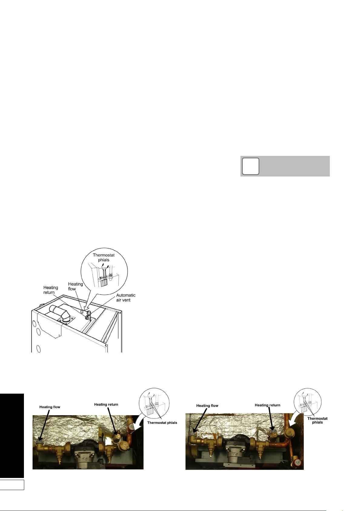
Flow connection: A 22 mm pipe is
provided for the flow connection. This
is located on the top of the boiler. The
pipe will need to be vented, as it is
the highest point on the primary heat
exchanger.
Return connection: A 22 mm pipe
is provided for the return connection.
This is located on the top of the boiler.
The pipe will also need to be vented at
some point, as it is the highest point on
the secondary heat exchanger.
NOTE
!
All pipes to be fitted into the push-fit
connectors provided
should be cut using a pipe slicer or
pipe cutter - to leave
the pipe ends with a slight radius
and free from any burrs
or sharp edges. Pipes to be used
with these fittings should
not be cut square using a hacksaw.
16
Figure 5-1: Water connections and themostat phial positions (utility models)
Figure 5-2: Water connections and themostat phial
positions (15/21 and 21/26 system models)
Figure 5-3: Water connections and themostat phial
positions (26/35 system models)
Page 17
6 Condensate Disposal
6.1 General Requirements
When in condensing mode the Grant
VORTEX Eco boilers produce
condensate from the water vapour
in the flue gases. This condensate is
slightly acidic with a ph value of around
3 (similar to vinegar). Provision must be
made for the safe and effective disposal
of this condensate.
Condensate can be disposed of
using one of the following methods of
connection:
Internal connection (preferred
option):
• into an internal domestic
wastesystem (from kitchen sink,
washing machine, etc.)
• directly into the soil stack
External connection:
• into an external soil stack
• into an external drain or gulley
• into a rainwater hopper (that is
part of a combined system where
sewer carries both rainwater and
foul water)
• purpose made soakaway
All condensate disposal pipes must
be fitted with a trap - whether they are
connected internally or externally to a
domestic waste system/soil stack or run
externally to a gully, hopper or
soakaway.
6.2 Connections
Connections into a rainwater hopper,
external drain or gulley should be
terminated inside the hopper/drain/
gulley below the grid level but above
the water level.
Condensate disposal pipes should not
be connected directly into rainwater
downpipes or to waste/soil systems
connected to septic tanks.
Condensate should not be discharged
into ‘grey water’ systems that re-use
water used in the home (not including
water from toilets).
It should be noted that connection of a
condensate pipe to the drain may
be subject to local Building Control
requirements.
Condensate disposal pipes should
have a minimum ‘nominal’ diameter
of 22 mm (¾”) - e.g. use 21.5 mm OD
polypropylene overflow pipe.
Condensate disposal pipes must be
fitted with a fall (away from the boiler) of
at least 2.5° (~45 mm fall per metre
run).
NOTE
!
Where it is not possible for the
pipe to fall towards the point of
discharge - either internally into
a waste system or externally to a
gulley (e.g. for boilers installed in
a basement), it will be necessary to
use a condensate pump.
Condensate disposal pipes should
be kept as short as possible and the
number of bends kept to a minimum.
Pipes should be adequately fixed to
prevent sagging, i.e. at no more than
0.5 metre intervals.
6.4 External Pipework
Ideally, external pipework, or pipework
in unheated areas, should be avoided. If
unavoidable, external pipework should
be kept as short as possible (less than
3 metres) and 32 mm waste pipe used
to minimise the risk of ice blocking the
pipe in freezing conditions.
The number of bends, fittings and joints
on external pipes should be kept to a
minimum to reduce the risk of trapping
condensate.
NOTE
!
For boiler installed in an unheated
area such as an outhouse or
garage, all condensate pipework
should be considered as an
‘external’.
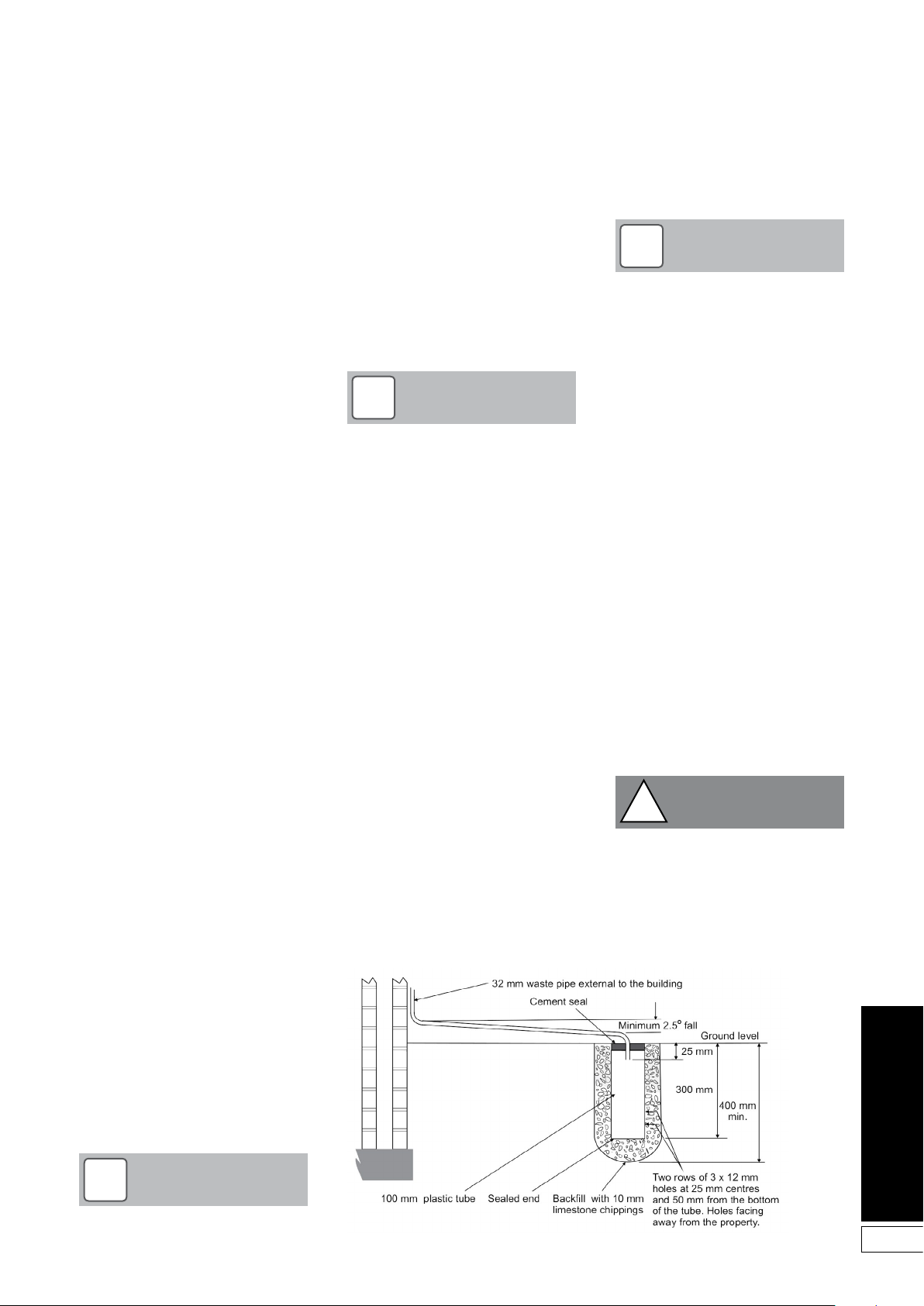
6.5 Condensate Soakaway
To keep external pipework to a
minimum, locate the soakaway as close
as possible to the boiler but ensure
it is at least 500 mm from building
foundations and away from other
services, e.g. gas, electricity, etc.
The condensate pipe may be run above
or below ground level and can enter
either the top or side of the soakaway
tube. Refer to Figure 6-1.
Ensure that the drainage holes in the
soakaway tube face away from the
building.
Backfill both the soakaway tube,
and the hole around it, with 10 mm
limestone chippings.
Only use a soakaway where the soil is
porous and drains easily. Do not use
in clay soils or where the soil is poorly
drained.
CAUTION
!
Any damage due to condensate
backing up into the boiler due to a
high water table, in the case of a
soakaway, or flooded drains when
the condensate disposal is via a
gulley or soil stack, is not covered
by the Grant product guarantee.
6.3 Pipework
Condensate disposal pipework must be
plastic (plastic waste or overflow pipe is
suitable).
NOTE
!
IMPORTANT: Copper or steel pipe is
NOT suitable and MUST NOT be used.
Figure 6-1: Purpose made condensate soakaway
17
Page 18
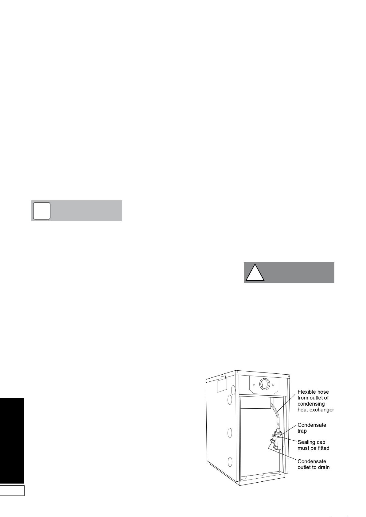
6.6 Condensate Trap
Grant VORTEX Eco boilers are supplied
with a factory-fitted condensate trap to
provide the required 75 mm water seal
in the condensate discharge pipe from
the boiler.
This trap incorporates a float (which will
create a seal when the trap is empty)
and an overflow warning outlet (fitted
with a plastic sealing cap), see Figure
6-2.
The trap is factory-fitted inside the boiler
casing, mounted in the rear of the boiler
(opposite end to the burner) on the
inside of the side panel, see Figure 6-2.
NOTE
!
Access must be available to allow
for routine maintenance.
A flexible hose connects the outlet of
the condensing heat exchanger to the
trap inlet. Ensure the straight connector
on the hose is fully pushed onto the ‘top
hat’ inlet connector of the trap.
With the trap fitted inside the boiler
casing, the sealing cap must be fitted.
If connecting the condensate discharge
(either internally or externally) into a
waste system or soil stack - the sealing
cap must be fitted in the trap outlet.
On external discharge systems to a
hopper, gully or soakaway, the sealing
cap should be removed from the trap
outlet.
If there is any discharge of condensate
from the overflow outlet, this could
indicate a blockage (possibly due
to freezing). Turn off the boiler and
investigate the cause. If necessary
contact your service engineer for
assistance.
The condensate trap outlet is at an
angle of 48° below the horizontal. This
is to automatically give a 3° fall on any
‘horizontal’ runs of condensate disposal
pipe. Refer to Figure 6-2.
6.7 Condensate Disposal
Pipework
The outlet of the trap will accept 21.5
mm to 23 mm OD Polypropylene
overflow pipe for the condensate
discharge pipe.
Possible routes for disposal
pipework
The boiler enclosure has several 50 mm
diameter openings in both the sides
and base. These are designed to allow
pipework to pass through, to suit the
installation. These openings can be
used to allow the condensate disposal
pipe to exit the casing in one of the
following ways:
Side outlet – The lower opening on
either side of the enclosure can allow
the condensate disposal pipe to be
installed as follows:
• Connection to an internal stack –
passing back through the wall of
the house.
• Connection to an external soil
stack adjacent to the boiler.
• Discharge into an adjacent
(external) drain or gulley.
• Discharge into a soakaway – with
pipe either above or below ground
level.
Bottom outlet – There are three
openings in the base that can allow
the condensate disposal pipe to be
installed as follows:
• Discharge into a drain or gulley
beneath the boiler (e.g. drain built
in to the concrete base for the
boiler).
• Discharge into a soakaway – with
pipe below ground level.
When connecting plastic discharge
pipe, ensure that the pipe is fully
pushed into the outlet end on
the flexible pipe to prevent the
possibility of leakage.
6.8 Inspection and Cleaning of
Trap
The trap must be checked at regular
intervals (e.g. on every annual service)
and cleaned as necessary to ensure
that it is clear and able to operate.
The bottom bowl is sealed to the
trap body and cannot be removed.
To inspect and clean the trap:
1. Disconnect flexible condensate
hose from inlet connector.
2. Unscrew the inlet connection nut.
3. Remove the inlet connector and
nut from trap.
4. Remove trap from bracket.
5. Remove float from trap – clean if
necessary.
6. Inspect inside of trap and clean as
necessary.
7. Re-assemble trap, re-fit to boiler
and re-connect flexible hose.
Ensure that hose is fully pushed
onto the trap inlet connector.
CAUTION
!
Failure to regularly check and clean
the condensate trap may result in
damage to the boiler and will not be
covered by the guarantee.
18
Figure 6-2: Condensate trap (rear panel removed)
Page 19
7 Sealed Systems
7.1 Sealed System Installation
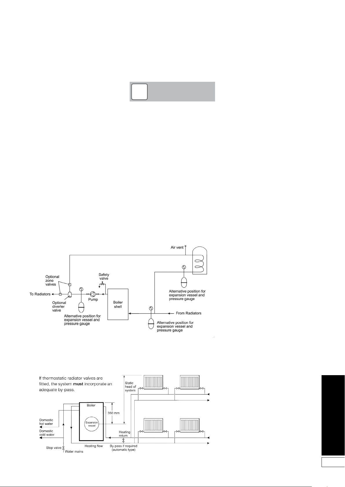
See Figure 7-1
All Grant VORTEX Eco boilers are
suitable for use with sealed systems
complying with the requirements of BS
EN 12828:2003, BS EN 12831:2003, BS
EN 14336:2004.
The maximum temperature of the
central heating water is 75°C.
The system must be provided with the
following items:
• Diaphragm expansion vessel
complying with BS EN 13831:2007.
• Pressure gauge.
• Safety valve.
• Approved method for filling the
system.
Figure 7-1: Sealed system
NOTE
!
Ensure that the expansion vessel
used is of sufficient size for the
system volume. Refer to BS
7074:1:1989 or The Domestic
Heating Design Guide for sizing the
required vessel.
The expansion vessel can be fitted in
either the return or flow pipework in any
of the recommended positions as
shown in Figure 7-1. To reduce the
operating temperature of the expansion
vessel diaphragm, position it below
the pipe to which it is connected. The
expansion vessel may be positioned
away from the system, providing the
connecting pipe is not less than 13 mm
diameter.
The pressure gauge should have an
operating range of 0 to 4 bar.
The safety valve, set to operate at 2.5
bar, should be fitted in the flow
pipework near to the boiler.
The pipework between the safety valve
and boiler must be unrestricted, i.e.
no valves. The safety valve should be
connected to a discharge pipe which
will allow the discharge to be seen,
but cannot cause injury to persons or
property.
Provision should be made to replace
water lost from the system. This can
be done manually (where allowed by
the local water undertaking) using
an approved filling loop arrangement
incorporating a double check valve
assembly (as supplied in the Sealed
System kit).
An automatic air vent should be fitted to
the highest point of the system.
The expansion vessel charge pressure
should always be slightly greater than
the maximum static head of the system,
in bar, at the level of the vessel (1 bar =
10.2 metres of water). See Figure 7-2.
The system fill pressure (cold) should
be 0.2 - 0.3 bar greater than the vessel
charge pressure – giving typical system
fill pressures of approx 0.5 bar for a
bungalow and 1.0 bar for a two storey
house. Refer to the Domestic Heating
Design Guide for further information if
required.
If thermostatic radiator valves are fitted
to all radiators, a system by-pass must
be fitted.
Filling of the system must be carried
out in a manner approved by the local
Water Undertaking.
Where allowed, the system may be filled
via the filling loop supplied (the loop
arrangement includes a double check
valve assembly).
All fittings used in the system must be
able to withstand pressures up to 3 bar.
Radiator valves must comply with the
requirements of BS 2767:1991.
One or more drain taps (to BS 2879)
must be used to allow the system to be
completely drained.
Figure 7-2: Boiler with sealed system kit
19
Page 20

20
7.2 System Models
All System models have the following
sealed system components factory
fitted (refer to Figure 7-3):-
• A diaphragm expansion vessel
complying with BS 4814, precharged at 1.0 bar. Refer to
Section 2.2.
• System pressure gauge, with an
operating range of 1 to 4 bar.
• Pressure relief safety valve
complying with BS 6759 and set to
operate at 2.5 bar.
• Automatic air vent, fitted to the
flow pipe of the boiler, ensures the
boiler is vented.
• Filling loop. This must be isolated
and disconnected after filling the
system.
Refer to Section 2.2 for system volumes
and BS 7074: for further guidance and
for further details of the expansion
vessel.
The expansion vessel fitted, is supplied
with a charge pressure of 1.0 bar
(equivalent to a maximum static head of
10.2 metres). The charge pressure must
not be less than the actual static head
at the point of connection.
CAUTION
!
Do not pressurise the vessel above
1.5 bar.
NOTE
!
The air pressure in the vessel must
be checked annually.
The central heating system volume,
using the expansion vessel as supplied,
must not exceed the recommended
value. Refer to Section 2.2. If the system
volume is greater, an extra expansion
vessel (complying with BS 4841) must
be fitted as close as possible to the
central heating return connection on the
boiler.
The charge pressure of the extra vessel
must be the same as the vessel fitted in
the boiler.
Refer to either BS 7074:1:1989 or
The Domestic Heating Design Guide
for the required total expansion
vessel volume for the system
concerned.
NOTE
!
The air charge pressure may be
checked using a tyre pressure
gauge on the expansion vessel
Schraeder valve. The vessel may
be re-pressurised using a suitable
pump. When checking the air
pressure the water in the heating
system must be cold and the system
pressure reduced to zero.
7.3 Fill the Sealed System
Automatic air vent(s) are fitted to the top
of the boiler (see Figure 7-3). Check that
the small cap on the top of each air vent
is screwed on fully, then unscrew it one
complete turn - the cap remains in this
position from now on.
The procedure for filling the sealed
system is as follows:
1. Only ever fill or add water to the
system when it is cold and the
boiler is off. Do not overfill.
2. Ensure that the flexible filling
loop supplied with the boiler is
connected and that the double
check shut off valve connecting it
to the water supply is closed.
A valve is open when the operating
lever is in line with the valve, and
closed when it is at right angles
to it.
3. Open the fill point valve.
4. Gradually open the double check
valve from the water supply until
water is heard to flow.
5. When the white needle of the
pressure gauge is between 0.5 and
1.0 bar, close the valve.
6. Vent each radiator in turn, starting
with the lowest one in the system,
to remove air.
7. Continue to fill the system until the
pressure gauge indicates between
0.5 and 1.0 bar. Close the fill point
valve.
8. Repeat steps 4 and 5 as required.
9. Close the fill point and double
check valves either side of the
filling loop and disconnect the loop.
7.4 Pressure Relief Safety
Valve
Now the pressure relief safety valve
operation must be checked and set. The
procedure is as follows:
1. Check the operation of the
safety valve by turning the head
anticlockwise until it clicks. The
click is the safety valve head lifting
off its seat allowing water to escape
from the system
2. Check that the water is escaping
from the system.
3. Continue to fill the system until the
pressure gauge indicates between
0.5 and 1.0 bar.
4. Close the fill point valve and check
the system for water soundness,
rectifying where necessary.
5. Water may be released from the
system by manually operating the
safety valve until the system design
pressure is obtained. The system
design pressure (cold) should be
between 0.5 bar and 1.0 bar.
The pressure is equivalent to the
maximum static head in bar + 0.3 (1
bar = 10.2 metres of water), where the
static head is the vertical height from
the centre of the expansion vessel to the
highest point of the system.
Now close the valves either side of the
filling loop and disconnect the loop.
Page 21

7.5 Circulating Pump
7.5.1 Pump Specification
Make and model Wilo Yonos PARA RS 15/7.0 RKC FS 130 12
Construction
Pump housing Cast iron (with cataphorisis treatment)
Impellar PP composite with GF 40%
Pump shaft Stainless Ste el
Bearing Carbon, metal impregnated
Protection Class IPx4D
Insulation Class F
Motor Protection Integrated
Performance
Max. delivery head 7.2m @ Q = 0 m3 /h
Max. volume flow 3.3 0 m3 /h
Minimum suction head @ 50/95°C 0.5/4.5m
Power consumption @ 1 - 230V 3-45W
Nominal Motor Power 37W
Current @ 1 - 230V 0.028 - 0.44 A
Energy Efficiency Index (EEI) ≤ 0.20
Speed 800-4650 rpm
Settings ∆P-variable (1-7m head) and Constant Speed (I, II and III)
Application
Maximum Static Pressure PN6
Temperature range @ ma ximum ambient temperatures Ma ximum ambient temperature 57°C: 0 to 95°C
Maximum ambient temperature 59°C: 0 to 90°C
Maximum ambient temperature 67°C: 0 to 70°C
Approved Fluids Heating Water
Water/Glycol - Max 1:1 (above 20% check pumping data)
21
Page 22
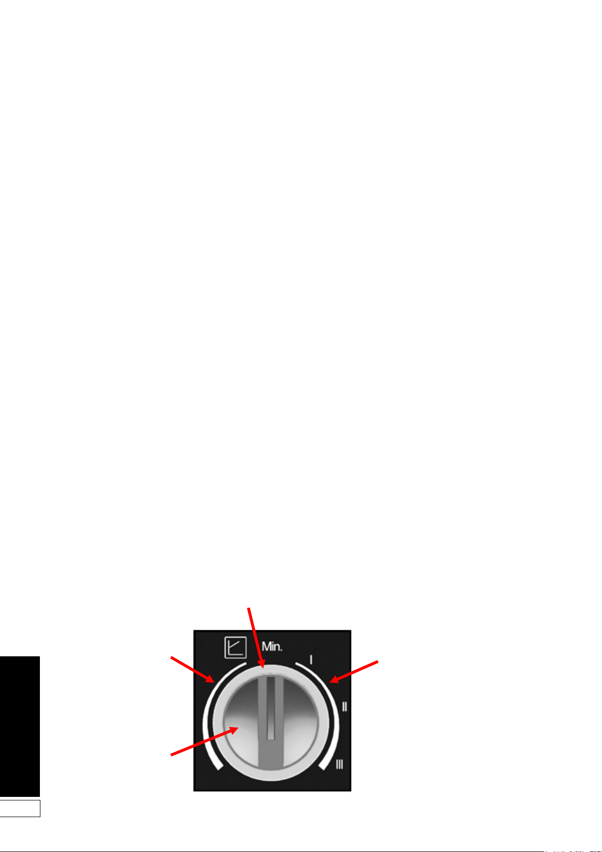
7.5.2 Pump Control Panel
Wilo Yonos PARA RKC circulating
pumps have two possible setting
modes:
• Constant speed with three pump
speed settings (I, II and III)
• Variable pressure (∆p-v) with pump
head adjustable between 1 and 7m
head
Figure 7-3 shows the pump control
panel with the red selector knob.
Constant Speed Mode (I, II, III)
This is the default setting of the pump
and as such is recommended by Grant
for heating systems. In this mode
the pump speed is not automatically
regulated (as with the Variable Pressure
Mode), but operates at constantly at
one of the three possible speeds (set
using the red selector knob on the pump
control panel).
Variable Pressure Mode (
In this mode the electronic control
changes the differential pressure
setpoint to be maintained by the pump
in a linear fashion between Hs (the value
set using the red selector knob on the
pump control panel) and ½ Hs. The
differential setpoint varies linearly with
the volume flow Q.
∆p-v)
7.5.3 Indicator LED
The pump is fitted with an indicator
LED. This is located around the
circumference of the red selector knob.
See Figure 7-3 below. This indicates the
operating status of the pump and will
be illuminated green when the pump is
operating normally. This indicator LED
can assist in diagnosing and rectifying
faults. Refer to Section 12.3.
7.5.3 Setting the Pump Control Mode
Set the pump to one of the two
operating modes as follows:
Constant Speed Mode (I, II, III)
Grant recommends this operating mode
for the pump.
To set the pump to the ‘Constant
Speed’ mode, the pointer on the red
selector knob must be set to the RIGHT
of the mid position. Refer to Figure 7-3.
Set it to point at the required speed
setting, I, II or III as required, ensuring
that there is adequate flow to distribute
the heat from the boiler whilst avoiding
high water velocities causing noise in
the pipework.
Variable Pressure Mode (
To set the pump to the ‘Variable
Pressure’ mode the pointer on the red
selector knob must be set to the LEFT of
the mid position. Refer to Figure 7-3.
The further anticlockwise it is set the
greater the pressure head setting of the
pump – from 1m to 7m head.
If this mode is to be used, set the
selector knob at a pressure that
represents the maximum pressure
(head) loss for the heating system in
question.
∆p-v)
22
Indicator LED
Variable Pressure Mode
settings: 1 to 7m head
Red selector knob
Figure 7-3: Control panel with red selector knob and LED indicator
Constant Speed Mode
settings: I, II, III
Page 23

8 Electrical
The VORTEX Eco External module
requires a 230/240 V ~ 50 Hz supply. It
must be protected by a 5 Amp fuse.
Refer to Figures 8-1 to 8-4 for typical
control system wiring diagrams.
Refer to Figure 8-3 for boiler internal
wiring diagram.
WARNING
!
The VORTEX Eco boiler contains
electrical switching equipment and
must be earthed.
The supply must be fused at 5 Amp
and there must only be one common
isolator for the boiler and control
system, providing complete electrical
isolation.
A fused double pole switch or a
fused three pin plug and shuttered
outlet socket should be used for the
connection.
The power supply cable should be at
least 0.75 mm² PVC as specified in BS
6500, Table 16.
All the wiring and supplementary earth
bonding external to the boiler must
be in accordance with the current IET
Wiring Regulations.
Any room thermostat or frost thermostat
used must be suitable for use on mains
voltage.
The boiler requires a permanent mains
supply, do not interrupt it with any
external time controls.
In the event of an electrical fault after
installation of the boiler, the following
electrical system checks must be
carried out:
• Short circuit
• Polarity
• Earth continuity
• Resistance to earth
8.1 Connecting the Power
Supply
NOTE
!
A test switch is fitted to the control
panel (see Figure 1-1) to allow the
boiler to be test-fired. When On,
the switch by-passes the external
control system.
It is recommend that the boiler should
be connected to a switched mains
power supply from a programmer
or control system. If a Grant remote
programmer is used, a permanent 240
V mains supply (fused at 5 Amp) must
be taken to the boiler. A three core
cable is required to connect the boiler
terminal block to the live supply. Refer
to Figures 8-1 to 8-2 for typical control
system wiring diagrams.
The procedure is:
1. Undo the three screws and remove
the lefthand cover from the control
panel to gain access to the boiler
terminal block.
2. Pass the mains power supply
cable through the cable grommet
in the control panel, through the
cable clamp and connect to the
terminal block as follows:
Brown to live (terminal 2)
Blue to mains neutral (terminal 3)
Green/Yellow to mains earth
(terminal 4)
3. Refer to Figures 8-1 to 8-2 for
a typical control system wiring
diagrams.
4. If the circulating pump is to be
fitted within the boiler enclosure,
the pump live must be connected
to terminal 7 of the boiler terminal
block.
Pass the pump power supply
cable through the cable grommet
in the control panel, through the
cable clamp and connect to the
terminal block as follows:-
Brown to live (terminal 7)
Blue to mains neutral (terminal 9)
Green/Yellow to earth (terminal 10)
Connecting the pump in this way
allows it to be isolated using the
isolating switch fitted in the boiler
control panel, for servicing or
maintenance work.
5. Ensure that the cable clamp is
tightened and that all cables are
secure and all external wiring is
adequately supported.
6. Replace the cover on the control
panel, with the yellow warning label
facing outwards and secure with
the three screws.
Do not switch on the electricity supply
to the External module at this stage.
8.2 Frost Protection
External Modules are supplied with a
factory fitted frost protection thermostat,
located inside the boiler control panel
This is pre-wired to the boiler electrical
system and factory set to 2°C.
For total system protection against
freezing, particularly during extended
periods without electrical power, Grant
recommend the use of a combined
heating system antifreeze and corrosion
inhibitor, used in accordance with the
manufacturer’s instructions.
23
Page 24
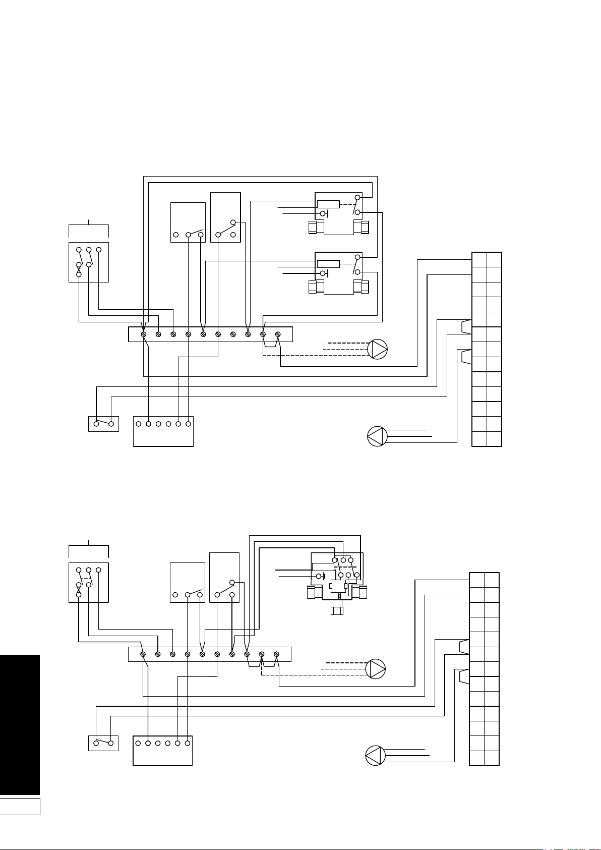
8.3 Control System Wiring Diagrams
Wall Mounted
Programmer ESKIT
Wall Mounted
Programmer ESKIT
Grey
Grey
5A
240V
50HZ
L N E
Blue
Brown
Pipe Stat
(If fitted)
Green/Yellow
Cylinder
Room
Stat
2 1 3
Stat
1
C
2
1 2 3 4 5 6 7 8 9 10
N
L 1 2 3 4
OFF OFF ON ON
HW HT HW HT
Grant 2-Channel
Link
Brown
Blue
Brown
Blue
Orange
Orange
Green/Yellow
Green/Yellow
Wiring
Centre
HW
Motor
2-Port Zone Valve
HTG
Motor
2-Port Zone Valve
Green/Yellow
Blue
Brown
Boiler Terminal Block
(Remove link 5 to 6
when pipe stat fitted)
E
N
Pump
L
E
Green/Yellow
N
L
Blue
Brown
Pump (System boiler only)
10
11
12
13
1
L
2
L
3
N
4
E
5
6
7
8
L
9
N
E
L
N
E
Figure 8-1: CH and HW controlled by two 2-port zone valves
5A
240V
50HZ
L N E
Blue
Brown
Pipe Stat
(If fitted)
Green/Yellow
Cylinder
Room
Stat
2 1 3
Stat
1
C
2
1 2 3 4 5 6 7 8 9 10
N
L 1 2 3 4
OFF OFF ON ON
HW HT HW HT
Grant 2-Channel
Link
Orange
Grey
White
Link
Blue
Green/Yellow
Motor
13k2W270k
0.25W
3-Port Mid Position
Zone Valve
Wiring
Centre
Green/Yellow
Blue
Brown
Boiler Terminal Block
(Remove link 5 to 6
when pipe stat fitted)
E
N
L
Pump
Green/Yellow
E
N
L
Blue
Brown
Pump (System boiler only)
10
11
12
13
1
L
2
L
N
3
4
E
5
6
7
8
L
9
N
E
L
N
E
24
Figure 8-2: CH and HW controlled by 3-port mid position zone valve
Page 25
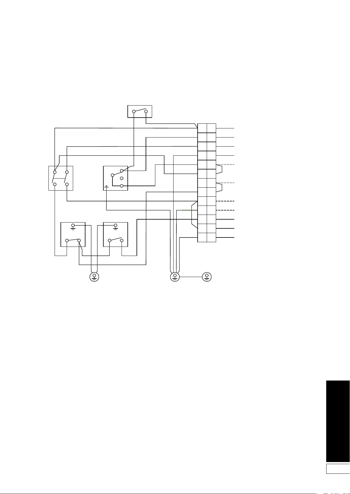
8.4 Boiler Control Panel Wiring Diagram
Control box
chassis earth
Control box
chassis earth
Earth to
switch cover
Test switch
Mains
Boiler
On/Off
Switch
Red
Blue
Yellow
5B 2A
Frost
Thermostat
4B 1A
Limit
Thermostat
C 2 C 1
Red
Red Red
Red
Control
Thermostat
Red
Yellow
Yellow
Red
Red
Yellow
Blue
Green/Yellow
Yellow
Yellow
Red
Blue
Green/Yellow
Red
Blue
Green/Yellow
Green/Yellow
1
L
2
L
3
N
4
E
5
Switched Live
Permanent Live
Mains Neutral
Mains Earth
To CH Valve if required
Yellow
6
Brown
Pump Live
Pump Neutral
}
Pump Earth
Burner Live
Burner Neutral
Burner Earth
Pump factory fitted
and wired on system
models only
7
8
L
9
N
10
E
11
L
12
N
13
E
Figure 8-3: Control panel wiring
25
Page 26
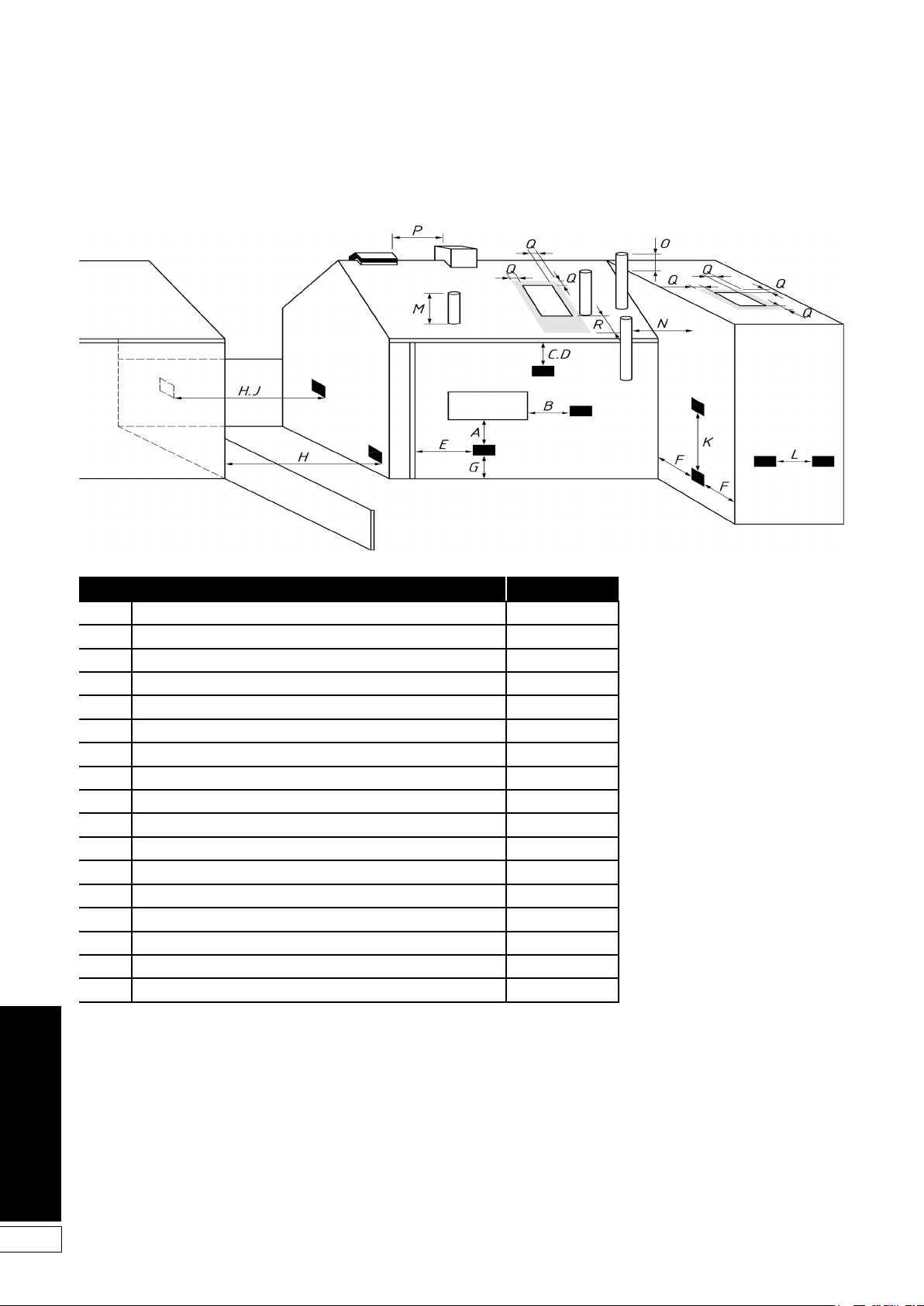
9 Flue System and Air Supply
Figure 9-1: Clearances for
balanced flue terminals
Permission to reproduce extracts from British Standards is granted by
BSI Standards Limited (BSI). No other use of this material is permitted.
Location Appliances *
A Directly below an opening, air brick opening, opening window, etc. 1000
B Horizontally to an opening, air brick opening, opening window, etc. 1000
C Below a gutter, eaves or balcony with protection 1000
D Below a gutter or a balcony without protection 1000
E From vertical sanitar y pipework 300
F From an internal or external corner 300
G Above ground or balcony level 300
H From a surface or boundar y facing the terminal 2500
J From a terminal facing the terminal 1200
K Vertically from a terminal on the same wall 1500
L Horizontally from a terminal on the same wall 750
M Above the highest point of an intersection with the roof 600
N From a vertical structure to the side of the terminal 750
O Above a vertical structure less than 750mm from the side of the terminal 600
P From a ridge terminal to a vertical structure on the roof 1500
Q Above or to the side of any opening on a flat or sloping roof 300
R Below any opening on a sloping roof 1000
* Minimum distances to terminals in millimetres as measured from top of the chimney or the outer edge of a low level discharge opening.
26
NOTE: Vertical structure in N, O and P includes tank or lift rooms, parapets, dormers, etc.
NOTE: Terminating positionings A to L are only permitted for appliances that have been approved for low level flue discharge when tested in accordance with BS
EN 303-1, OFS A100 or OFS A101.
Terminating positions should be at least 1.8 m from an oil storage tank unless a wall with at least 30 min fire resistance and extending 300 mm higher and wider
than the tank is provided between the tank and the terminating position.
Where a flue is terminated less than 600 mm away from a projection above it and the projection consists of plastics or has a combustible or painted surface, then a
heat shield of at least 750 mm wide should be fitted to protect these surfaces.
For terminals used with vaporizing burners, a horizontal distance of at least 2 300 mm should be between the terminal and the roof line.
If the lowest part of the terminal is less than 2 m above the ground, balcony, flat roof or other place to which any person has access, the terminal should be
protected by a guard.
Notwithstanding the dimensions given above, a terminal should not be sited closer than 300 mm to combustible material. In the case of a thatched roof, double
this separation distance should be provided. It is also advisable to treat the thatch with a fire retardant material and close wire in the immediate vicinity of the flue.
A flue or chimney should not pass through the roof within the shaded area delineated by dimensions Q and R.
Where protection is provided for plastics components, such as guttering, this should be to the standard specified by the manufacturer of the plastics components.
Page 27
9.1 Air Supply
A permanent air supply must be
provided to the burner, sufficient to
ensure proper combustion of fuel and
effective discharge of combustion
products to open air.
The ventilation openings provided in the
upper part of the front door of the boiler
casing must not be obstructed at any
time.
9.2 Low Level Discharge Flue
The Grant VORTEX Eco External module
is supplied with a low level discharge
flue (see Section 4).
The minimum dimensions for locating
the standard terminal from building
features (windows, doors, etc.) are
shown in Figure 9-1.
The terminal must be positioned so
as to avoid products of combustion
accumulating in stagnant pockets
around the buildings or entering into
buildings. Care should be taken that the
plume from the condensed flue gases
does not cause a nuisance.
Where it is not practical to use this flue,
the external module may be fitted with
an alternative flue system available from
Grant UK.
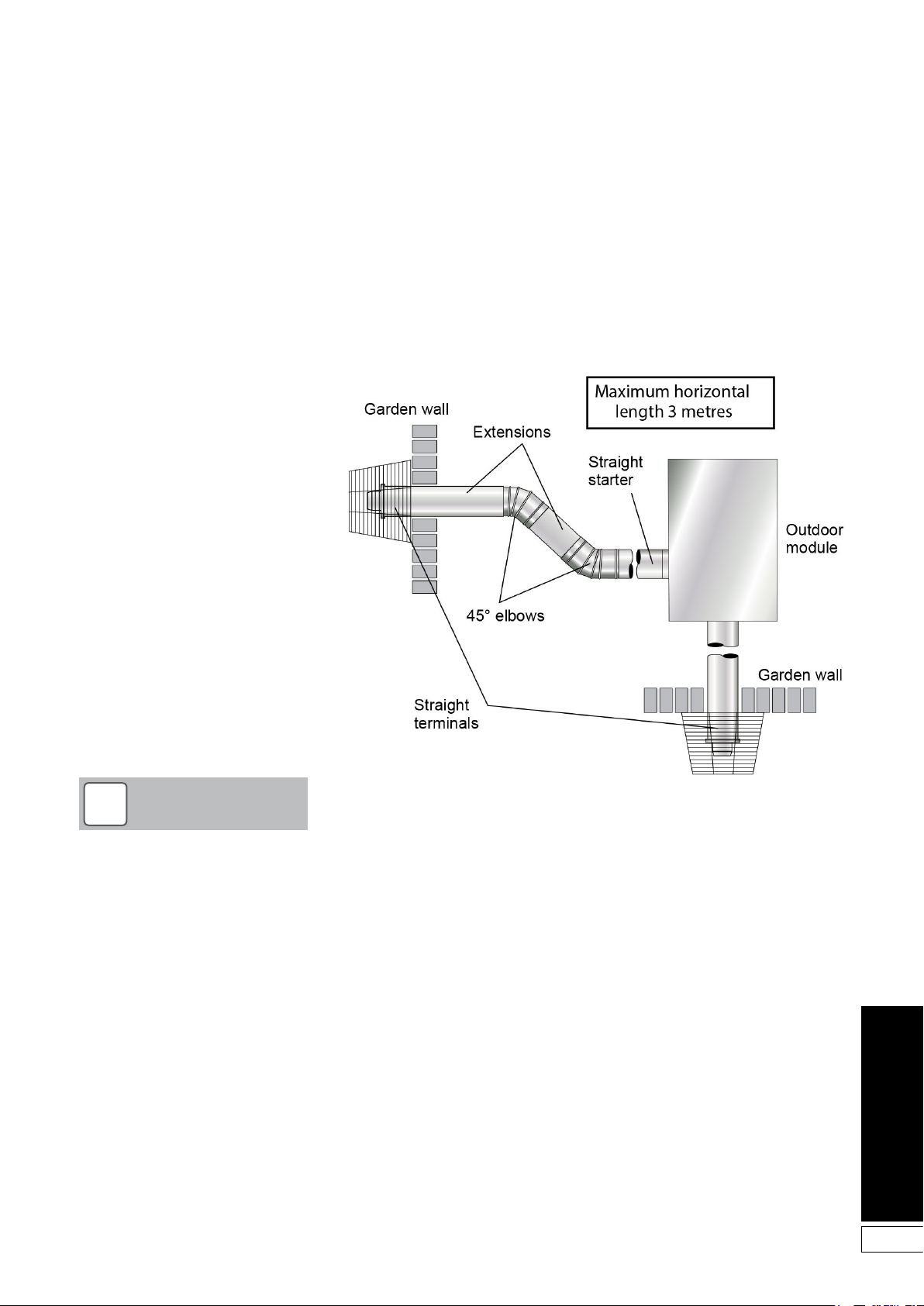
9.3 Grant Horizontal System
This option uses the Grant Straight
Starter boiler connector, replacing
the low level terminal and flue guard
supplied with the boiler, along with
components from the Grant Green
system. See Figure 9-2.
A complete list of Grant Green system
flue components are given on page 28.
NOTE
!
Under no circumstances can the
external module be installed with an
existing flue system. Only Grant flue
systems and components suitable
for wet flues should be used.
Failure to install the correct type
of flue system will invalidate the
guarantee.
Figure 9-2: Horizontal external flue
27
Page 28
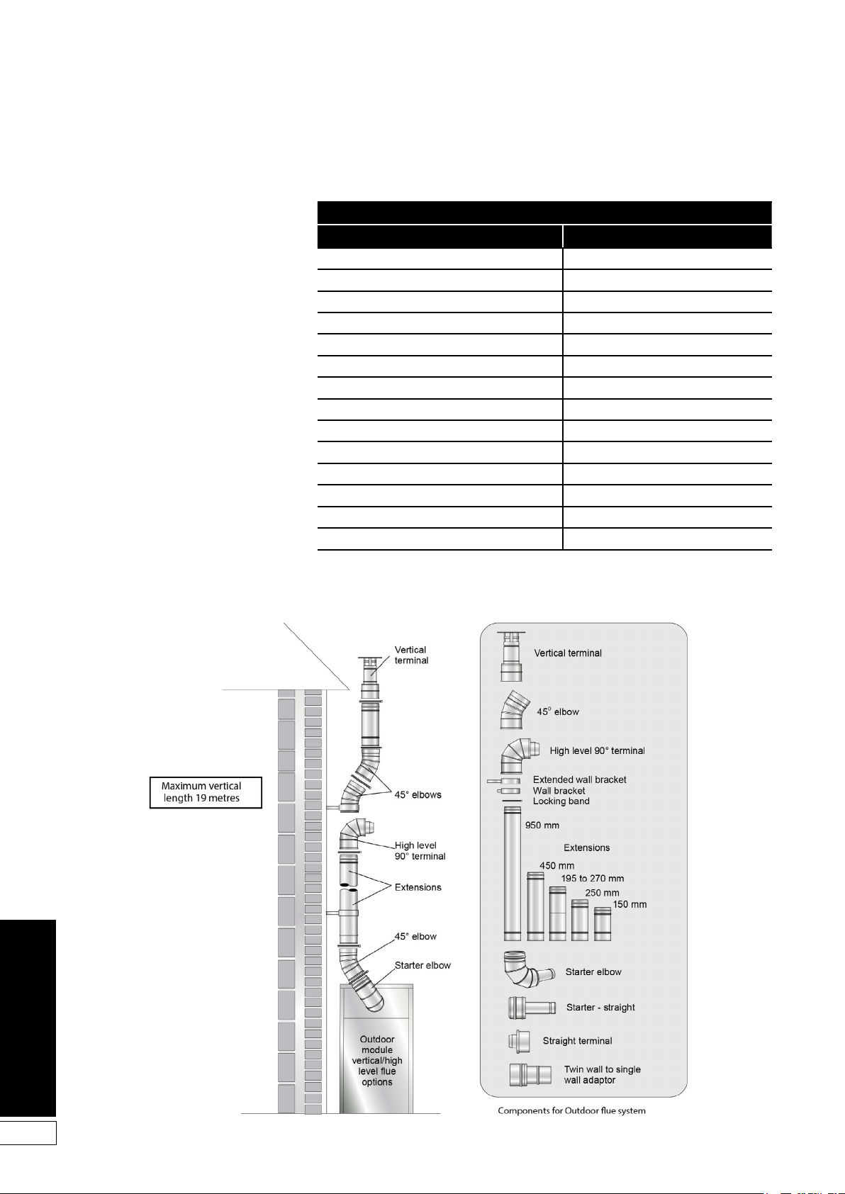
9.4 Grant Green System
This vertical twin wall stainless steel
insulated flue system - constructed
using components from the Grant Green
system - connects to a Grant Starter
elbow and may terminate at high level or
vertically as required. See Figure 9-3.
The insulated Starter elbow includes
the boiler connector, complete with test
point, replacing the low level terminal
and flue guard supplied with the boiler.
Green System components
Item Part number
External starter elbow GKM90
External starter - straight GKM90C
150 mm extension GX150/90
250 mm extension GX250/90
450 mm extension GX450/90
950 mm extension GX950/90
195-270 mm ajudtable extension GXA250/90
45° elbow GE45/90
High level terminal GTH90
Vertical terminal GTV90
Wall bracket - standard GWB90
Wall bracket - extended GEB90
Twin wall to single wall adaptor GFCON80
Straight terminal - horizontal flue GTL90
28
Figure 9-3: Vertical external conventional flue (Green system)
Page 29
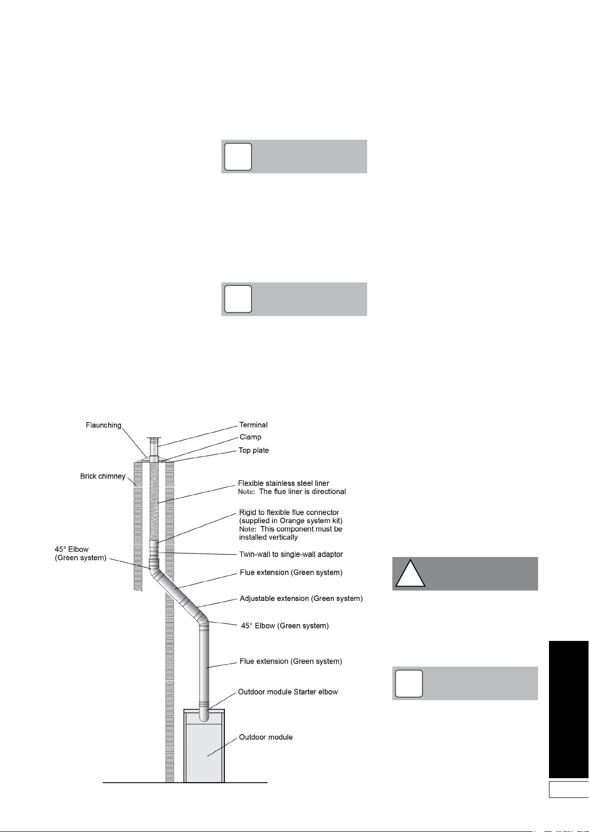
9.5 Grant Hybrid System
This vertical option allows the use of
an existing chimney using part of the
‘Green’ system and the flexible liner and
terminal of the Grant ‘Orange’ system.
See Figure 9-4.
If an existing chimney is to be used,
it must be lined with a smooth bore
stainless steel liner suitable for use with
oil fired condensing boilers. The top and
bottom of the annular space must be
sealed.
Grant recommends the use of the
Grant ‘Orange’ flue system, specifically
designed for the VORTEX range of
condensing boilers.
The internal flue and liner diameter for all
models up to 46 kW output must be 100
mm (4 inch).
The maximum vertical height (from
the top of the boiler to the terminal) for
the‘Orange’ system is 19 metres.
NOTE
!
The Grant Orange system flexible
stainless steel liner is directional.
The arrows marked on the liner
MUST be pointing vertically
upwards, following the direction of
the flue gases. Failure to comply
with this instruction could lead to a
leakage of condensate from the flue
liner.
NOTE
!
In order to correctly connect the
Grant hybrid system, it will be
necessary to purchase the Grant
Starter Elbow.
This insulated Starter elbow
includes the boiler connector,
complete with test point, replacing
the low level terminal and flue guard
supplied with the boiler.
9.6 Conventional Flue Systems
All flue components are stainless steel
and fully insulated with ‘O’ ring seals
and locking bands.
The flue must terminate in a down
draught free area, i.e. at least 600 mm
above the eves or point of exit through
the roof, or preferably above the ridge
level.
The condensate may be allowed to run
back into the boiler. A condensate drain
at the base of the flue system is not
required.
The flue terminal must be at least
600 mm from any opening into the
building, and 600 mm above any
vertical structure or wall less than a
horizontal distance of 750 mm from
the terminal.
No part of any flue system should be
made of an asbestos material; aluminium must not be used in any part of the
flue.
Only stainless steel flue components
should be used.
If the draught conditions are
satisfactory, the flue should terminate
with a standard cowl.
Refer to the locally applicable Building
Regulations, BS 5410:1 and OFTEC
Installation Requirements (OFTEC
Technical Books 2 and 4) for further
guidance on conventional flue systems.
Do not use fire cement. The use of
high temperature silicone sealants is
recommended.
Figure 9-3: Vertical hybrid flue (Green to Orange system)
CAUTION
!
It is important to ensure that the
flue system is sealed and that
condensate cannot escape. Up
to 1.5 l/h of condensate can be
produced in a conventional flue
system.
NOTE
!
To comply with the requirements of
the Building Regulations Approved
Document J - conventional flue
systems must have a flue data plate.
A suitable data plate is supplied
with the Grant Orange flue system
and should be displayed next to the
boiler or flue.
29
Page 30
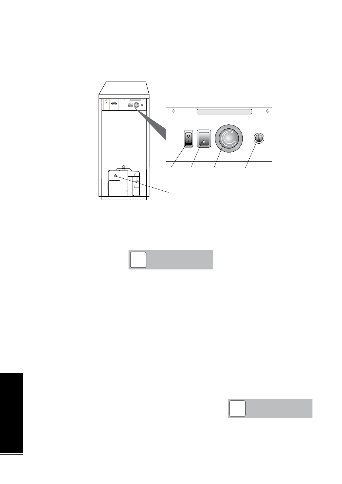
10 Commissioning
THERE IS MORE THAN ONE LIVE SUPPLY TO
DANGER
THIS CONTROL PANEL
HEATING
TEST
THERMOSTAT
OVERHEAT
BOILER
SWITCH
RESET
OFF
BOILER ON/OFF SWITCH
ISOLATES PUMP(IF WIRED
INTO BOILER CONTROL
PANEL) & BURNER ONLY.
THIS COVER ISTO BE
REMOVED BYQUALIFIED
PERSONNELONLY
DO NOTREMOVE COVER
WITHOUTISOLATING
SWITCHED LIVEAND
FROST'STAT
PERMANENTLIVE
TESTSWITCH
OVERIDES SYSTEM
CONTROLSTO
OPERATE BOILER
PRO EXTERNAL
OFF
ON ON
REFER TO WIRING DIGRAM IN MANUAL
DANGER
TEST
SWITCH
OFF
ON ON
REFER TO WIRING DIAGRAM IN MANUAL
Control Panel
THERE IS MORE THAN ONE LIVE SUPPLY TO
THIS CONTROL PANEL
BOILER
OFF
HEATING
THERMOSTAT
OVERHEAT
RESET
30
Boiler front
panel removed
Figure 10-1: Boiler controls
It is important that the following
commissioning procedure is carried out
to ensure safe and efficient operation of
the boiler.
To access the controls, remove the front
panel (turn the handle and withdraw it
forwards at the bottom).
The controls are shown in Figure 10-1.
10.1 Before Switching On
1. Ensure the boiler On/Off switch and
the test switch are set to OFF.
2. Check that the high limit thermostat
and boiler thermostat bulbs are
correctly located in their respective
pockets. Refer to Figure 5-1.
Check condition of thermostat
capillaries, not damaged, broken or
kinked and not crushed.
3. Remove the nuts and washers
securing the front cleaning door.
Withdraw the door - take care it is
HEAVY!
4. Check that the turbulators are in
position and that the ends are
vertical.
5. Check that the baffles are in
position. Refer to Figures 11-1 or
11-2 as required.
6. Re-fit the cleaning door and check
it is fitted correctly and that a good
seal is made.
7. Remove and check the burner.
Check that the burner head is
correct.
Refer to Section 2.3.
Test
switch
Boiler
On/Off switch
thermostat
‘Lock-out’ reset button
Check the electrodes are set correctly.
Refer to Figure 11-6.
Check the nozzle is correct for the
output rating required. Refer to Section
2.3.
NOTE
!
If a 15/21 model is down rated, the
burner air adjuster disc must be
adjusted to setting B as described
in Section 10.6. Refer also to
Section 2.3.
If a 21/26 or 26/35 model is down
rated, the burner head must be
changed to a T1 head. See Section
11.4. Refer also to Section 2.3.
8. Check that the water system has
been vented (and pressurised if
sealed system) and there are no
leaks.
9. Ensure the automatic air vent on
the condensing heat exchanger is
open.
10. Check that all fuel line valves are
open.
11. Remove the plastic burner cover if
it was not previously removed.
12. Connect a combined vent manifold
and pressure gauge to the
pressure gauge connection port on
the oil pump. See Figure 3-6. Open
the vent screw on the vent manifold
to vent the supply while the pump
is running.
13. Check that all system controls are
calling for heat and turn the boiler
thermostat to maximum.
Boiler
Overheat thermostat
reset button
(under screw cover)
10.2 Switching On
1. Switch on the electricity supply.
2. Set the Boiler On/Off switch to ON.
A neon in the switch lights when it
is in the ON position.
The boiler will now light
automatically.
Note that the neon lights when the
boiler is switched on, but does not
necessarily indicate the burner is
firing.
3. The burner fan should start and the
burner should light within about 12
seconds.
If the burner does not light and
the ‘Lock-out’ reset button lights,
wait for about 45 seconds then
press the reset button to restart the
ignition process.
This procedure may have to be
repeated several times during first
lighting.
4. With the burner alight, check the
fuel pressure.
5. Refer to the Technical Information,
Section 2.3.
6. Adjust the pressure if necessary see Figure 3-6.
NOTE
!
It is important that the oil pressure
is correctly set.
7. Operate the boiler until it reaches
normal operating temperature.
Check oil supply/return pipe for
leaks, rectifying where necessary.
Page 31
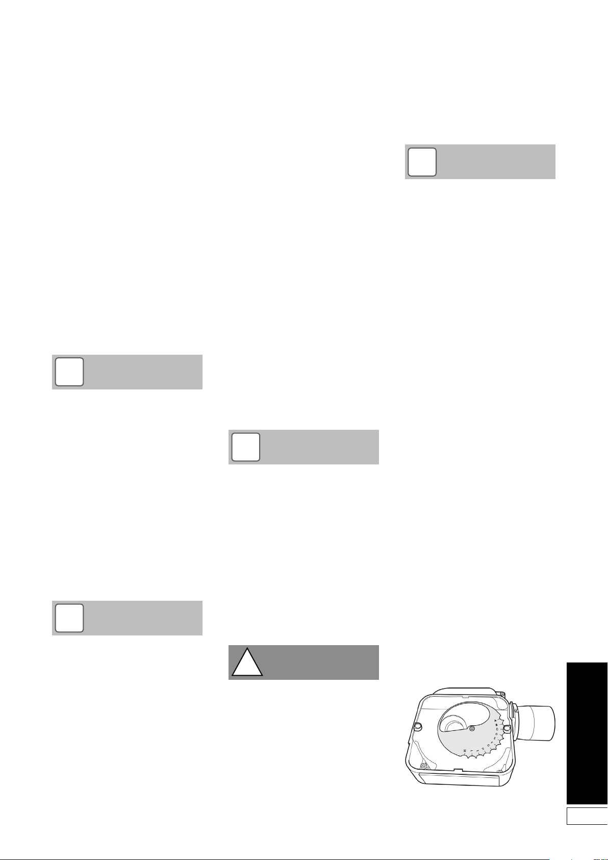
8. Check the operation of the boiler
thermostat. Ensure that by turning
it anticlockwise it switches the
burner off.
9. With the burner alight, re-check
the fuel pressure and re-adjust
if necessary. Turn the boiler off,
remove the pressure gauge and
replace the plug in the pump
10. Ensure that there are no oil leaks,
replace the burner cover.
10.3 Running the Boiler
1. Relight the boiler and allow it to run
for at least 20 minutes.
2. Check the smoke number, if
satisfactory check the CO2. Set the
CO2 to the value given in Section
2.3 for the boiler concerned.
NOTE
!
Final combustion readings can
only be measured outside through
the low level flue terminal (or the
test point on the conventional flue
starter elbow when used) with all
the casing panels fitted.
3. Use the hexagonal key supplied to
adjust the burner air damper (see
Figure 3-6) as required. Turning
the screw anti-clockwise closes
the damper and increases CO2
level, turning the screw clockwise
opens the damper and reduces
CO2 level.
4. Re-check the smoke number if the
damper has been moved. Under
no circumstances must the smoke
number be above 1.
NOTE
!
It is important that the air damper is
correctly set.
5. Check the flue gas temperature by
placing the combustion analyser in
the low level flue terminal (or into
the test point on the starter elbow if
either the Green system or Hybrid
system is used).
10.4 Balancing the System
1. When the boiler has been adjusted
and is running satisfactorily,
balance the central heating system
by adjusting the radiator lock
shield valves. Start with the radiator
nearest the boiler and adjust the
valves to achieve the required
temperature drop across each
radiator. If thermostatic radiator
valves have been installed, check
the system by-pass.
2. Switch off the boiler.
10.5 Completion
1. With the system hot, check
again for leaks, rectifying where
necessary.
Drain the system while it is hot to
complete the flushing process.
Refill and vent (and pressurise if a
sealed system) the system.
2. A suitable central heating system
inhibitor must be added to protect
the system against the effect of
corrosion.
3. A suitable antifreeze should be
used to prevent damage to the
boiler in areas where electrical
power failure can occur in winter
months.
4. Replace the top, front and rear
panels as necessary.
NOTE
!
After commissioning the boiler
complete the Commissioning Report
in the front of this manual and the
OFTEC CD/11 commissioning
report.
Leave the top copy with the User
and retain the carbon copy.
If the boiler is to be left in service with
the User, set the controls and room
thermostat (if fitted) to the User’s
requirements.
If the boiler is not to be handed over
immediately, close the boiler fuel supply
valve and switch off the electricity
supply.
CAUTION
!
If there is any possibility of the
boiler being left during frost
conditions, then the boiler and
system should be drained.
Alternatively, a suitable antifreeze
should be used.
To allow the boiler to be commissioned
and serviced correctly a combustion
test point is provided on the front
cleaning door.
The CO2 and smoke test may all be
carried out using this test point.
NOTE
!
The test point is not suitable for
measuring boiler efficiency or
conventional flue draught.
When using the test point on the
cleaning cover note that the flue gas
temperature reading will be higher than
that measured in the flue thus resulting
in an inaccurate efficiency reading. To
obtain an accurate flue gas temperature
and efficiency, the reading can only be
measured outside through the low level
flue terminal or the test point on the
conventional flue starter elbow when
fitted - with all the casing panels fitted.
10.6 Air Adjuster Disc - 15/21
only
To adjust the 15/21 air adjuster disc
when downrating - See Figure 10-2.
1. Ensure the boiler is isolated from
the electrical supply.
2. Remove the burner from the boiler.
3. Undo the two screws and remove
the air inlet cover from the side of
the burner.
4. The secondary air shutter disc
is factory set in position ‘C’ – i.e.
with the cut-out marked C located
against the die-cast boss on the
fan housing - suitable for outputs
of 18.3 and 21 kW only. See Figure
10-2.
5. Remove the screw from the
centre of the air shutter disc, and
re-position the disc such that the
cut-out ‘B’ (corresponding to 15
kW output setting – See Section
2.3) is located against the cast
boss on the fan housing. Replace
the screw in the centre of the air
shutter disc and tighten.
6. Re-fit the air inlet cover to the side
of the burner and reassemble in
reverse order.
Figure 10-2: 15/21 air adjuster disc at
position ‘C’
31
Page 32
11 Boiler Servicing
To ensure efficient operation of the
boiler it is recommended that it is
checked and serviced as necessary
at regular intervals. The frequency of
servicing will depend upon the particular
installation conditions and usage, but
in general once per year should be
adequate.
Servicing and replacement of parts
must only be carried out by a suitably
qualified engineer.
CAUTION
!
Details of every service should be
entered in the Service Log, in the
Boiler Handbook.
This information may be required
to validate the Grant extended
guarantee.
WARNING
!
Before starting any work on the
boiler, or fuel supply please read
the health and safety information
given in Section 14.
External equipment operated at
230 Volts should not be serviced
or repaired under adverse weather
conditions.
NOTE
!
A test switch is fitted to the control
panel to allow the boiler to be
testfired. When On, the switch
by-passes the external control
system.
11.1 Checking Before
Servicing
The following sequential checks should
be made before any servicing:
1. Check the flue terminal and ensure
it is not blocked or damaged.
2. Run the boiler and check the
operation of its controls.
3. Ensure that all water/fuel system
connections and fittings are sound.
Remake any joints and check the
tightness of any fittings that may be
leaking.
4. If the boiler is used on a sealed
central heating system, check
the system pressure, check the
operation of the pressure relief
valve and check the expansion
vessel air charge. See Section 7.2.
5. Refill, vent and re-pressurise the
system as necessary. See Section
7.3.
6. Check that the louvres in the front
panel are clear.
7. Remove any sludge/water from the
fuel tank by opening the sludge
valve at the lower end of the tank.
8. With the fuel supply valve closed,
clean/replace the filter element and
clean the filter bowl.
9. Braided flexible fuel supply hoses
(as supplied with the boiler) should
be replaced annually. If long-life
hoses have been installed, these
should be inspected annually.
If in doubt replace the hoses. In
any event, these hoses must be
replaced every five years.
WARNING
!
Before servicing, set the boiler
On/Off switch to Off, isolate the
electricity supply and close the fuel
supply valve.
Allow the boiler to cool.
The data label on the inside of the case
side panel will indicate the fuel used and
the nozzle fitted.
11.2 Dismantling Prior to
Servicing
The procedure for dismantling the boiler
is as follows:
1. Remove the front panel by turning
the handle and withdrawing it
forwards at the bottom.
2. Remove the four screws securing
the top panel and carefully lift it
off, taking care not to damage the
insulation.
NOTE
!
The top panel has been designed to
provide a slight fall away from the
side positioned against a wall, the
side of the top panel with the fixing
screws closer to the bottom edge is
the highest side and goes against
the wall.
2. If a sealed system kit is fitted,
carefully lift up and remove the
expansion vessel from the front of
the boiler. Place the vessel on the
floor taking care not to strain the
flexible hose.
3. Remove the burner fixing nut (top
of mounting flange) and withdraw
the burner.
If required, disconnect the flexible
oil hose(s), use a suitable container
NOTE
!
If two flexible hoses are connected
to the burner, identify (mark if
necessary) which is the inlet
and return if they are to be
disconnected.
32
Page 33
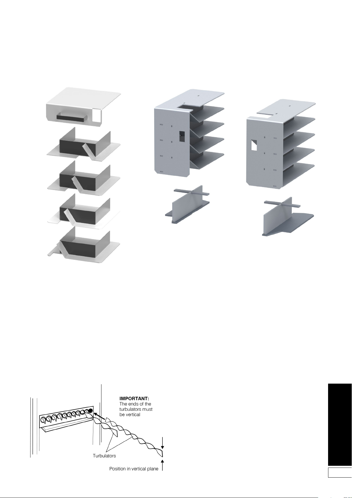
Figure 11-1: 15/21 and 21/26 baffles
Figure 11-2: 26/35 baffles
Figure 11-3: Turbulators
33
Page 34
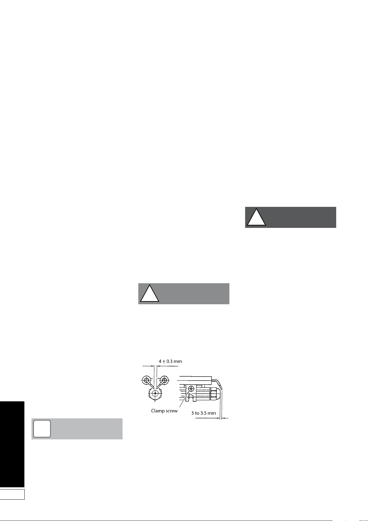
11.3 Cleaning the Boiler
The procedure for cleaning the boiler is
as follows:
1. Remove the nuts and washers
securing the front cleaning door
and withdraw the door. Take care it is heavy.
2. Remove the baffles as shown in
Figures 11-1 or 11-2.
3. Remove all deposits from the baffle
plates and all the boiler internal
surfaces using a stiff brush and
scraper if necessary.
4. Check the condition of the flue,
clean as necessary.
5. Check the condition of the front
cleaning door seal, replace if
necessary.
6. Replace the baffles, ensuring they
are correctly fitted. See Figures
11-1 or 11-2.
7. Pull out the spiral turbulators from
the heat exchanger tubes. See
Figure 11-3.
8. Clean the turbulators using a stiff
brush.
9. Test the heat exchanger
condensate drain by pouring
water into one of the lower tubes
and observe whether the water
discharges from the 22 mm
condensate outlet. Replace the
turbulators.
10. Replace the front cleaning door,
ensuring the seal is in good
condition and secure it in position
with the nuts and washers
previously removed.
Tighten to form a seal.
11. Remove the condensate trap
andcheck that it is not blocked and
is operating correctly, i.e. the float
is free to move. Clean the trap and
float as required. Refer to Section
6.8.
12. Check that the boiler condensate
outlet is unobstructed. Clean if
necessary.
11.4 Cleaning the Burner
The procedure is as follows:
1. Combustion head: Loosen the two
screws securing the combustion
head and withdraw the head.
2. Clean the combustion head.
3. Inspect the ignition electrodes:
Loosen the electrode clamp
screw and withdraw the electrode
assembly. Wipe clean and check
for any cracks in the ceramic
insulation.
Replace if necessary.
4. Nozzle: The nozzle should be
replaced on an annual service.
Check that the nozzle size and type
are correct, refer to table in Section
2.3 and boiler data label.
5. With the combustion head
removed, loosen the electrode
assembly clamp screw and slide
the electrodes away from the
nozzle.
6. Do not attempt to clean the nozzle.
7. Remove the nozzle using a good
fitting spanner (16 mm).
CAUTION
!
The use of an ill-fitting spanner will
damage the nozzle and could lead
to an incorrect flame pattern.
8. Always check the electrode
settings after replacing the nozzle,
see Figure 11-4.
Photocell - The photocell is a push-fit
in the burner body. Carefully pull it out
to clean.
Burner fan - With the air intake grille
or spigot removed, remove the screws
securing the fan housing cover (R/H
side of burner) and remove the cover.
Inspect the fan and housing and clean
as necessary. Replace the cover.
Pump filter - With the burner cover
removed, remove the four screws securing the pump end cover. Remove the
filter and wash in kerosene. Replace the
filter and end cover, ensure the ‘O’ ring
is in position.
Re-assemble in reverse order.
WARNING
!
To ensure safe and efficient
operation of the boiler it is important
that recommissioning is carried out,
especially combustion checks (CO2
level, flue gas temperature and
smoke number) after the boiler has
been serviced.
Refer to the Commissioning
instructions in Section 10.
34
NOTE
!
The condensate trap and
condensate outlet must be checked
on every service and cleaned as
necessary.
Figure 11-4: Electrode assembly
Page 35
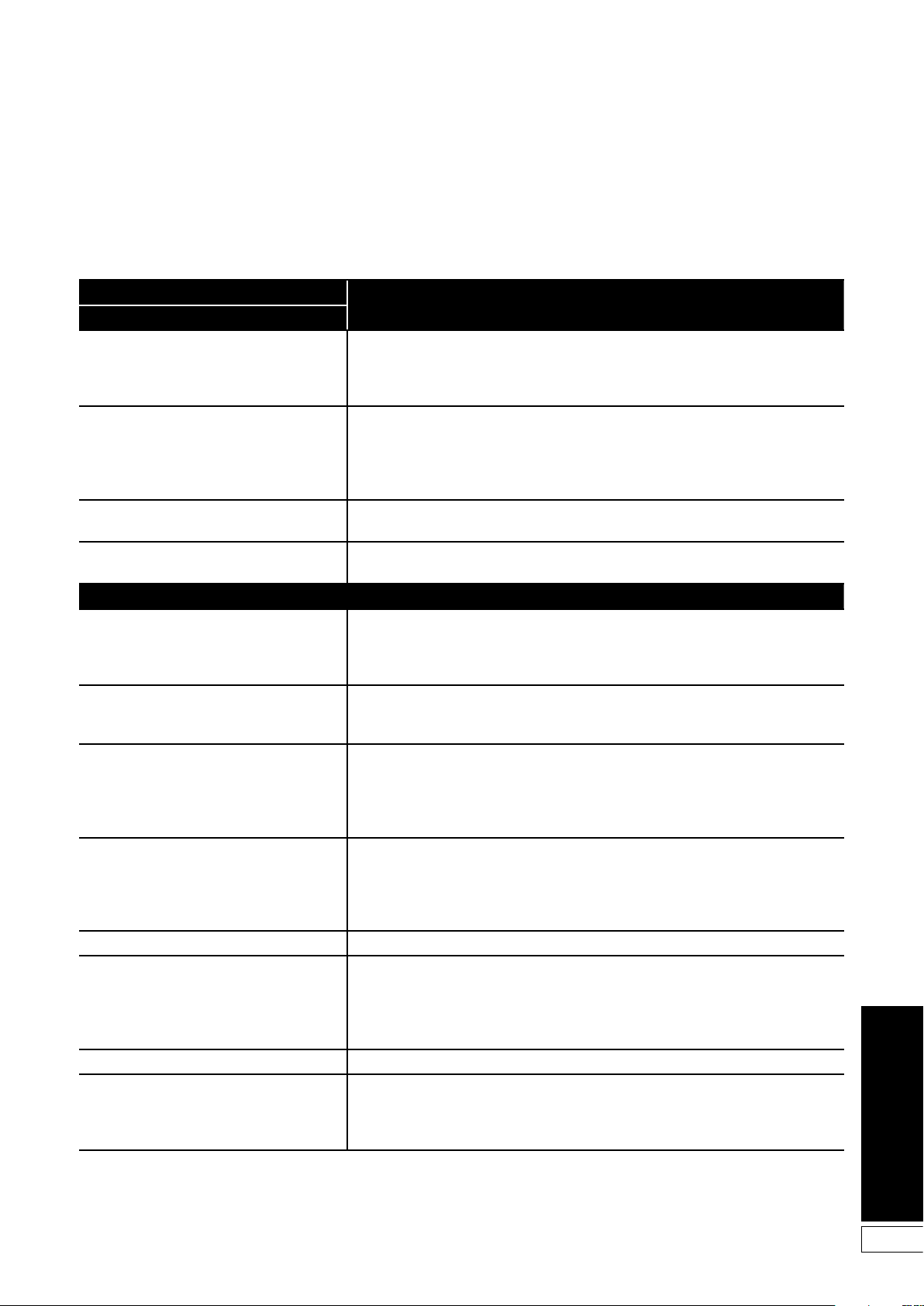
12 Fault Finding
12.1 Boiler Fault Finding
Always isolate the electricity supply to the boiler before working on the boiler.
Fault
Boiler will not start:
No fuel supply Ensure that an adequate supply of fuel is available and that the fuel supply valve is
No electricity supply Ensure electricity supply to the boiler is switched on and that all controls are calling
Burner not starting - fuel and electricity supplies present
Burner lights but goes to lock-out If the flame is unstable, check the combustion settings.
Boiler works but:
Visible smoke from flue or high smoke
number
Burner pulses Insufficient air supply - check the air damper setting and the condition of the fan.
Flame slow to stabilise during start up Insufficient air supply - check the air damper setting and the condition of the fan.
Water temperature low Undersize nozzle and/or low fuel pressure.
Boiler operating on overheat thermostat Faulty boiler thermostat. No circulation, check circulating pump. Check for air lock.
Fumes and puffing during starting (conventional flue)
Oil odours Check all fuel line connections, remake as necessary.
Combustion fumes smell Check boiler cleaning cover and seal are correctly fitted.
Remedies
open.
Check the condition of the fuel filter, clean if necessary.
Ensure fuel supply is reaching burner and vent pump.
for heat.
Ensure that the overheat thermostat has not tripped, reset if necessary.
Check that a mains supply is present at the burner terminal block.
If not, check the boiler and overheat thermostat.
Press the reset button on the burner control box if it is lit.
Refer to burner fault finding charts.
Refer to burner fault finding charts.
Insufficient air supply - check the air damper setting and the condition of the fan.
Check room ventilation is adequate, see Section 9.1.
Check the nozzle size and type.
Fuel pressure may be too high - check and adjust.
Check room ventilation is adequate, see Section 9.1.
Check the nozzle size and type.
Check room ventilation is adequate, see Section 9.1.
Check the nozzle size and type.
Fuel pressure may be too low - check and adjust.
Insufficient draught - clean boiler heat exchanger and check condition of flue.
Check condition of boiler heat exchanger and clean if necessary.
Check the boiler thermostat.
Check the combustion settings.
Check the condition of the fuel filter.
Check the condition of the chimney, ensure it is not blocked and is high enough to
produce the
required draught. Check that there is an adequate air supply near the burner and that
a kitchen
fan is not drawing products out of the burner.
Check burner is correctly fitted onto flange.
Check flue is correctly sealed into flue outlet of boiler.
Check the condensate pipe and trap are operating correctly
35
Page 36
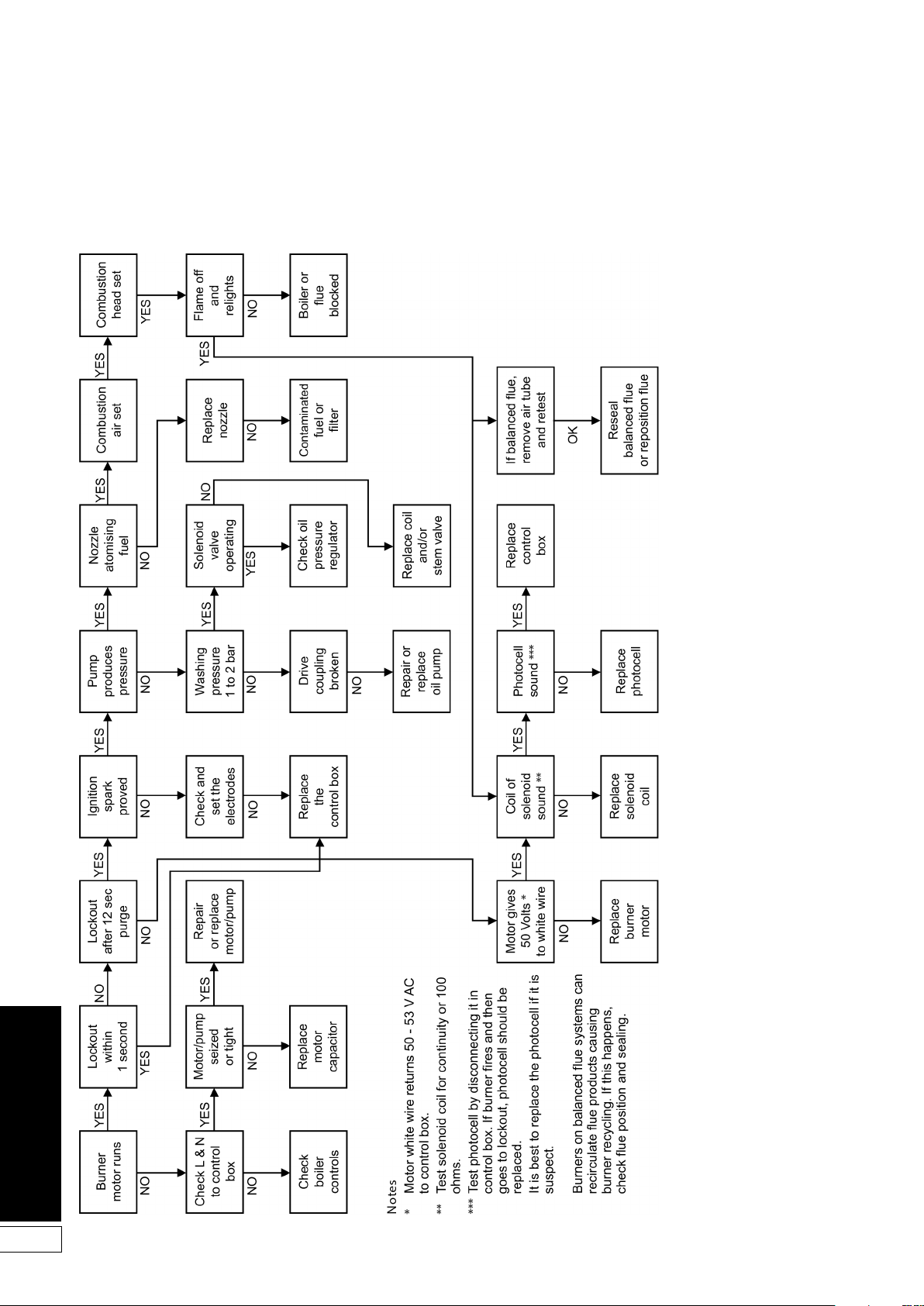
12.2 Burner Fault Finding - Riello RDB burners
36
Page 37
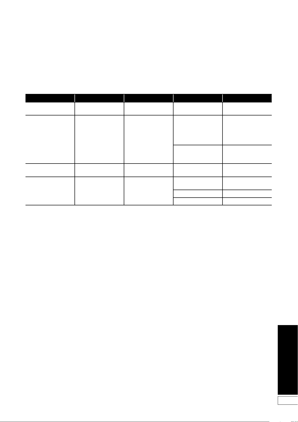
12.3 Circulating Pump Fault Diagnosis
The indicator LED, located around the circumference of the red control knob, can assit in diagnosing and rectifying a fault with the
pump. See the table below.
LED condition Meaning Diagnostic Cause Remedy
Green
Flashes red and
green
Flashes red
LED off
Pump operating Pump runs according to the
red knob setting
Pump is operating but
stoipped
Pump not operating Pump stopped (blocked) Pump does not restar t itself
No power supply No voltage to pump control
Pump restarts itself af ter
fault has disappeared
electronics
Normal operation N/A
Undervoltage
Voltage <160V
OR
Overvoltage
Voltage >253V
Overheating:
temperature inside motor
too high
due to a permanent failure
Pump is not connected to
power supply
LED is damaged Check if pump is running
Electronics are damaged Replace pump
Check supply voltage is
195V<V<253V
Check water and ambient
temperature
Replace pump
Check cable connection
37
Page 38
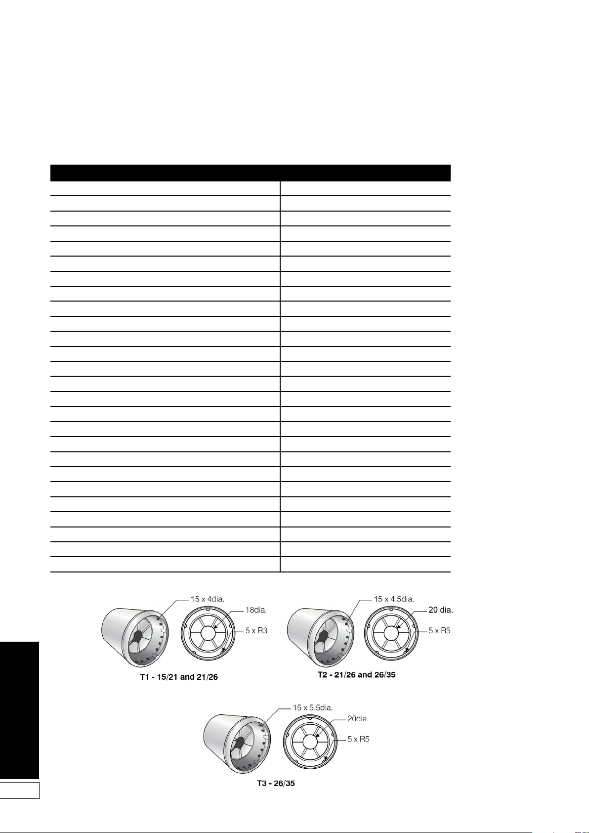
13 Spares Parts
13.1 Boiler Parts List
Description Part number
Cleaning door nut and washer set EFBS14
Double pole switch EFBS19
Test switch EFBS21
Frost thermostat EFBS23
Baffle set (complete) - 15/21 and 21/26 VBS96
Baffle set (complete) - 26/35 VBS97
Turbulator baffle - single VBS98
Sealed system - Expansion vessel 12 litre MPSS01
Sealed system - Water pressure gauge MPSS02
Sealed system pressure relief valve MPCBS50X
Sealed system - Expansion vessel flexible hose MPSS04
Cleaning door - 15/21 and 21/26 VBS92
Cleaning door - 26/35 VBS69
Cleaning door seal - 15/21 and 21/26 VBS20L
Cleaning door seal - 26/35 VBS15
Overheat thermostat TPBS33
Boiler thermostat TPBS34
Circulating pump - 6 m head (non HE) MPCBS23
Circulating pump - 7 m head (HE) VBS126
White pump cable with plug (for HE pump) VBS126A
Black pump cable with plug (for HE pump) VBS126B
Return connection assembly - 22 mm with automatic air vent VBS61
Automatic air vent MPCBS29
Condensate trap VBS02
Condensate flexible hose VBS104
Stainless steel flue guard FKS70
38
13.2 Burner Heads
Figure 13-1: Burner heads
Page 39
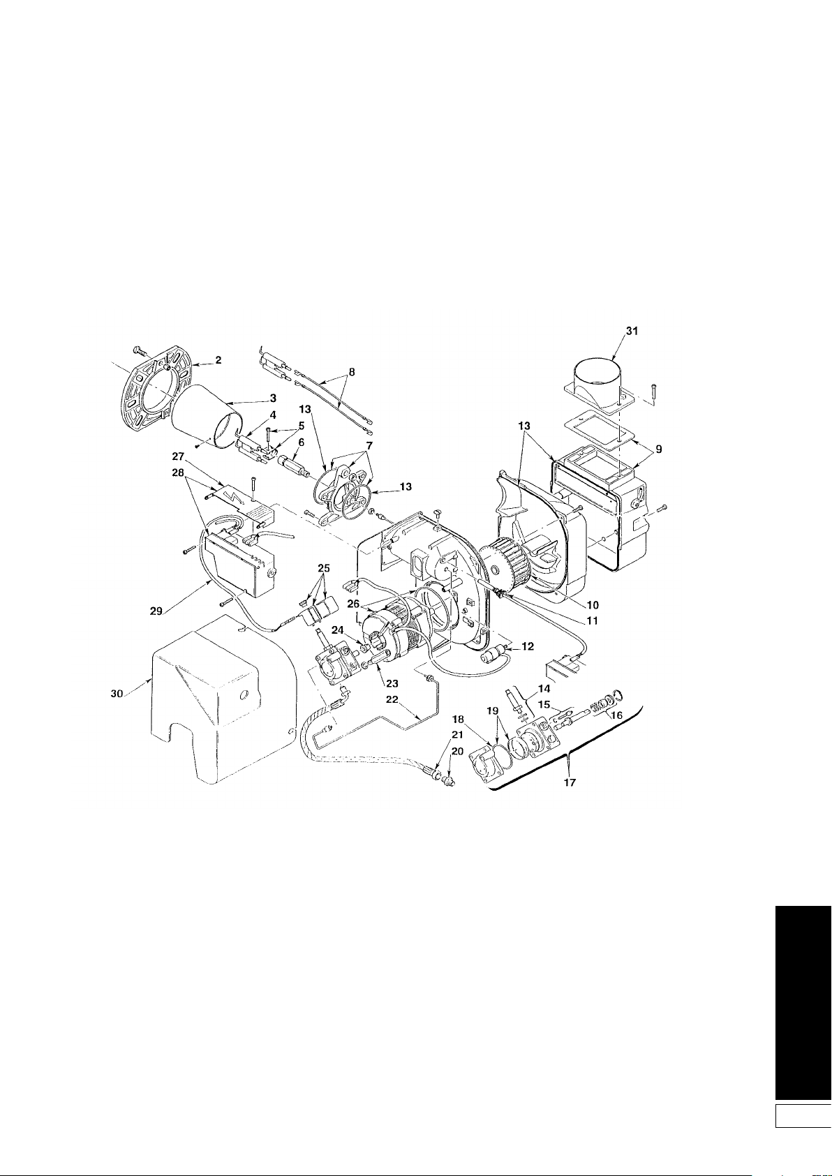
This section gives exploded views of the
Riello burners in the Grant VORTEX Eco
boilers, and parts lists associated with
them.
13.3 Riello RDB2.2 burner
Figure 13-2: Riello RDB2.2 burner components diagram
39
Page 40

Riello RDB2.2 burner parts list
Key number Description Riello part number Grant part number
1 Not applicable - -
2 Flange 3005786 RBS119
3 Combustion head T1 - 15/21 (21/26 - 20.7 kW) 3002507 RBS146
3 Combustion head T2 - 21/26 (26/35 - 25.6 kW) 3002423 RBS147
3 Combustion head T3 - 26/35 3002447 RBS144
4 Electrode assembly 3007513 RBS108
5 Electrode bracket 3006552 RBS29
6 Nozzle holder 3008642 RBS111
7 Collar 3008643 RBS112
8 High voltage lead 3008794 RBS129
9 Air damper assembly 3008647 RBS116
10 Fan - 15/21 3005788 RBS151
10 Fan - 21/26 3005708 RBS39
10 Fan - 26/35 3008645 RBS142
11 Photocell 3008646 RBS115
12 Capacitor 4.5 µF 3002837 RBS149
13 Seal kit 3008878 RBS140
14 Needle valve 3007582 RBS109
15 Regulator 3008651 RBS120
16 Pump seal 3000439 RBS14
17 Pump 3008654 RBS101
18 'O' ring 3007162 RBS08
19 Filter - 'O' ring 3008653 RBS122
20 Connector 3003602 RBS35
21 Flexible hose 3007672 RBS36
22 Tube 3008644 RBS113
23 Pressure gauge connector 3008876 RBS138
24 Drive coupling 3000443 RBS16
25 Solenoid 3008648 RBS117
26 Motor RBS102 3002836 RBS102
27 Cover 3008649 RBS118
28 Control box assembly 3008652 RBS103
29 Solenoid lead 3008851 RBS139
30 Cover 3008879 RBS141
31 Air tube spigot 3062774 RBS143
40
Page 41

14 Health and Safety Information
Under the Consumer Protection Act
1987 and Section 6 of the Health
and Safety at Work Act 1974, we
are required to provide information
on substances hazardous to health
(COSHH Regulations 1988).
Adhesives, sealants and paints used
in the manufacture of the product are
cured and present no known hazards
when used in the manner for which they
are intended.
The following other materials are
present in the product:
14.1 Insulation Materials
Material Types: Ceramic fibre board,
mineral wool.
Description: Rigid board, slabs,
sleeves, gaskets, ropes.
Known Hazards: May cause
temporary irritation or rash to skin. High
dust levels may irritate eyes and upper
respiratory system.
Precautions: Avoid unnecessary or
rough handling, or harsh abrasion of
boards. Normal handling and use of
material should not produce high dust
levels.
Avoid inhalation, and contact with skin
and eyes.
After handling always follow normal
good hygiene practices.
Protection: Use disposable gloves,
face mask and eye protection.
First Aid: Eyes - If irritation occurs,
wash eyes with copious amounts of
water.
If symptoms persist, seek immediate
medical advice.
Skin - If irritation occurs, wash under
running water before washing with soap
and water.
Inhalation - Remove to fresh air, drink
water to clear throat and blow nose to
remove dust/fibres.
Ingestion - Drink plenty of water.
14.2 Sealant Materials
Material Types: Silicone elastomer.
Description: Sealant and adhesive.
Known Hazards: Irritation to eyes.
Precautions: Avoid inhalation
of vapour, contact with eyes and
prolonged or repeated contact with
skin.
After handling always follow normal
good hygiene practices.
Protection: Use eye protection. Rubber
or plastic gloves should be worn where
repeated contact occurs and a face
mask worn when working in confined
spaces.
First Aid: Eyes - Flush eyes with water
for 15 minutes. Seek immediate medical
attention.
Skin - Wipe off and wash with soap and
water.
Inhalation - Remove to fresh air.
14.3 Kerosene and Gas Oil
Fuels (mineral oils)
Known Hazards: The effect of mineral
oils on the skin vary according to the
duration of exposure and the type of oil.
The lighter fractions remove the
protective grease naturally present on
the skin, leaving it dry, liable to crack
and more prone to damage by cuts,
abrasions and irritant chemicals.
Skin rashes (Oil acne) most often on
arms, but also on any part of the body
in contact with oil or oily clothing.
Contact with fuel oils can cause
dermatitis.
Precautions: Avoid as far as possible
any skin contact with mineral oil or with
clothing contaminated with mineral oil.
The use of a lanolin-based barrier
cream is recommended, in conjunction
with regular washing with soap and
rinsing with water to ensure all oil is
removed from the skin.
Take care to prevent clothing,
especially underwear, from becoming
contaminated with oil.
Do not put oily rags or tools in pockets,
especially trouser pockets.
Have first-aid treatment at once for an
injury, however slight.
Do not inhale any vapours from mineral
oils.
41
Page 42
15 Recycling and Disposal
In EU Countries
The following information is provided
to enable regulatory compliance with
the European Union (EU) directives
identified and any amendments made
to these directives when using electrical
or electronic equipment in EU countries.
Disposal of Electrical and Electronic
Equipment
European Union (EU) Directive 2002/96/
EC Waste Electrical and Electronic
Equipment (WEEE)
Do not dispose of electrical or
electronic equipment in landfill sites.
In the EU, it is the individual recipient’s
responsibility to ensure that discarded
electrical or electronic materials are
collected and recycled according to the
requirements of EU environmental law.
Disposal of Surplus Packaging
European Parliament and Council
Directive 94/62/EC Packaging and
Packaging Waste
Do not dispose of surplus packaging
in landfill sites. In the EU, it is the
individual recipient’s responsibility to
ensure that packaging materials are
collected and recycled according to the
requirements of EU environmental law.
In non-EU Countries
In non-EU countries, dispose of
electrical and electronic equipment and
all surplus packaging in accordance
with national and regional regulations.
Complies with EC Low voltage
Electromagnetic compatibility and Boiler
efficiency Directives.
Circulating Pump
The circulating pump must not be
disposed of in normal doimestic waste
as most of the materials used in it’s
construction can be recycled.
For details on how to responsibly
dispose of this pump, please visit:
www.wilo.com/recycling
42
Page 43

16 Guarantee
16.1 The Vortex Oil Boiler
Guarantee
You are now the proud owner of a
Grant Vortex condensing boiler from
Grant Engineering (UK) Limited which
has been designed to give years of
reliable, trouble free, operation.
Grant Engineering (UK) Limited
guarantees the manufacture of the
boiler including all electrical and
mechanical components for a period
of twelve months from the date of
installation4, provided that the boiler
has been installed in full accordance
with the installation and servicing
instructions issued.
This will be extended to a total period of
two years if the boiler is registered with
Grant Engineering (UK) Limited within
thirty days of installation4 and
serviced at twelve monthly intervals3.
See main Terms and Conditions below.
Registering the product with Grant
Engineering (UK) Limited
Please register your Grant Vortex
condensing boiler with Grant
Engineering UK Limited within thirty
days of installation. To do so visit
www.grantuk.com and follow the links
to the ‘Homeowners Zone’, where you
can register your boiler for a further
twelve months guarantee (giving two
years from the date of installation4).
This does not affect your statutory
rights1.
If a fault or defect occurs within the
manufacturer’s guarantee period
If your boiler should fail within the
guarantee period, you must contact
Grant Engineering (UK) Limited who
will arrange for the repair under the
terms of the guarantee, providing
that the boiler has been correctly
installed, commissioned and serviced
(if the appliance has been installed
for more than twelve months) by a
competent person and the fault is not
due to tampering, running out of oil, oil
contamination, debris, system water
contamination, misuse, trapped air or
the failure of any external components
not supplied by Grant Engineering (UK)
Limited, e.g. fire valve, motorised valve,
etc.
This two year guarantee only
applies if the boiler is registered
with Grant Engineering (UK) Limited
within thirty days of installation4
and is serviced after twelve
months3.
In the first instance
Contact your installer or commissioning
engineer to ensure that the fault does
not lie with the system components
or any incorrect setting of the system
controls that falls outside of the
manufacturer’s guarantee otherwise
a service charge could result. Grant
Engineering (UK) Limited will not be
liable for any charges arising from this
process.
If a fault covered by the
manufacturer’s guarantee is found
Ask your installer to contact Grant
Engineering (UK) Limited Service
Department on +44 (0)1380 736920
who will arrange for a competent
service engineer to rectify the fault.
Remember - before you contact
Grant Engineering (UK) Limited:
• Ensure the boiler has been
installed, commissioned and
serviced by a competent person
in accordance with the installation
and servicing instructions.
• Ensure there is oil to supply the
burner.
• Ensure the problem is not being
caused by the heating system
or its controls. Consult the boiler
handbook for guidance.
Free of charge repairs
During the two year guarantee period
no charge for parts or labour will be
made, provided that the boiler has been
installed and commissioned correctly
in accordance with the manufacturer’s
installation and servicing instructions, it
was registered with Grant Engineering
(UK) Limited within thirty days of
installation4 and, for boilers over twelve
months old, details of annual service is
available3.
The following documents must be
made available to Grant Engineering
(UK) Limited on request:
• Proof of purchase
• CD10 Installation Completion Form
(or equivalent document)
• CD11 Commissioning Report Form
(or equivalent document)
• Service documents (CD11 or
equivalent document)
Chargeable repairs
A charge may be made (if necessary
following testing of parts) if the
breakdown is due to any fault(s) caused
by the plumbing or heating system,
e.g. contamination of parts due to
system contamination, sludge, scale,
debris or trapped air. See ‘Extent of
manufacturer’s guarantee’.
Extent of manufacturer’s guarantee:
The manufacturer’s guarantee does not
cover the following:
• If the boiler has been installed for
over two years.
• If the boiler has not been installed,
commissioned, or serviced by a
competent person in accordance
with the installation and servicing
instructions.
• The serial number has been
removed or made illegible.
• Fault(s) due to accidental
damage, tampering, unauthorised
adjustment, neglect, misuse or
operating the boiler contrary to
the manufacturer’s installation and
servicing instructions.
• Damage due to external causes
such as bad weather conditions
(flood, storms, lightning, frost,
snow, or ice), fire, explosion,
accident or theft.
• Fault(s) due to incorrectly sized
expansion vessel(s), incorrect
vessel charge pressure or
inadequate expansion on the
system.
• Fault(s) caused by external
electrics and external components
not supplied by Grant Engineering
(UK) Limited.
• Problems caused by lack of oil
or faults with the oil storage and
supply system.
• Fault(s) due to contamination of
the oil storage and supply system,
e.g. water or debris.
• Bleeding or removing oil storage
tank contamination or blockages
from oil lines.
• Problems due to the flue system
being incorrectly fitted or not
installed to meet installation
requirements.
• Boiler servicing, de-scaling or
flushing.
• Cleaning out condensate traps/
discharge pipes or thawing out
frozen condensate pipework.
• Checking and replenishing system
pressure.
• Oil supply pipelines, electrical
cables and plugs, external controls
not supplied by Grant Engineering
(UK) Limited.
• Heating system components, such
as radiators, pipes, fittings, pumps
and valves not supplied by Grant
Engineering (UK) Limited.
• Instances where the oil boiler has
been un-installed and re-installed
in another location.
• Use of spare parts not authorised
43
Page 44

44
by Grant Engineering (UK) Limited.
• Consumable items including,
but not limited to, oil nozzles, oil
hoses, gaskets.
IMPORTANT
The nozzle and braided oil hose
supplied with the boiler are only
covered for the period up to the time of
the first service (twelve months). Both
must be changed on the first service
and on every annual service thereafter.
IMPORTANT
Do not wait until the fuel supply runs
out before you re-order. Sludge in the
bottom of the tank may be drawn into
the fuel lines. It is recommended that
the boiler is switched off when the new
oil supply is delivered and that the fuel
is allowed to settle for an hour before
restarting the boiler.
Terms of manufacturer’s guarantee:
• The Company shall mean Grant
Engineering (UK) Limited.
• The boiler must be installed by
a competent installer and in full
accordance with the relevant
Codes of Practice, Regulations
and Legislation in force at the time
of installation.
• The boiler is guaranteed for
two years from the date of
installation4, providing that after
twelve months the annual service
has been completed3 and the
boiler registered with the Company
within thirty days of installation.
Any work undertaken must be
authorised by the Company and
carried out by a competent service
engineer.
• The shell (heat exchanger) of the
oil boiler is also covered by a five
year parts only guarantee from
the date of installation4. This is
subject to the following:
• The boiler is operated
correctly, in accordance with
the installation and servicing
instructions.
• Proof is provided that the
system has been flushed or
chemically cleaned where
appropriate (refer to BS 7593)
and that the required quantity
of a suitable corrosion
inhibitor added.
• Proof of annual servicing
(including the checking of
any expansion vessels and
pressure relief valves) must
be provided if and when
requested by the Company.
IMPORTANT
Grant Engineering
(UK) Limited strongly
recommends that a Grant
Mag-One in-line magnetic
filter/s (or equivalent5) is
fitted in the heating system
pipework. This should
be installed and regularly
serviced in accordance with
the filter manufacturer’s
instructions.
• This guarantee does not cover
breakdowns caused by incorrect
installation, neglect, misuse,
accident or failure to operate the
boiler in accordance with the
manufacturer’s installation and
servicing instructions.
• The boiler is registered with the
Company within thirty days of
installation. Failure to do so does
not affect your statutory rights1.
• The balance of the guarantee
is transferable providing the
installation is serviced prior to the
dwelling’s new owners taking up
residence. Grant Engineering (UK)
Limited must be informed of the
new owner’s details.
• The Company will endeavour
to provide prompt service in
the unlikely event of a problem
occurring, but cannot be held
responsible for any consequences
of delay however caused.
• This guarantee applies to Grant
Engineering (UK) Limited boilers
purchased and installed on the UK
mainland, Isle of Wight, Channel
Islands and Scottish Isles only2.
Provision of in-guarantee cover
elsewhere in the UK is subject to
agreement with the Company.
• All claims under this guarantee
must be made to the Company
prior to any work being
undertaken. Invoices for call out/
repair work by any third party will
not be accepted unless previously
authorised by the Company.
• Proof of purchase and date of
installation, commissioning and
service documents must be
provided on request.
• If a replacement boiler is supplied
under the guarantee (due to a
manufacturing fault) the product
guarantee continues from the
installation date of the original
boiler, and not from the installation
date of the replacement4.
• The oil boiler must be connected
to a mains water supply
(installations utilising a private
water supply are not covered by
this guarantee).
• Breakdown/failure due to lime
scale will not be covered by this
guarantee.
• The replacement of a boiler under
this guarantee does not include
any consequential costs, such
as the removal or replacement of
worktops, kitchen units, etc.
• The boiler (excluding external
modules) must not be sited in a
location where it may be subjected
to frost.
Hard water advice
(for Combi boilers only)
If you live in a hard water area,
protection against scaling must be
given to the domestic hot water heat
exchanger of your combination boiler.
You should fit an appropriate scale
inhibitor or water softener as any
breakdown caused by water scaling
is not covered by the manufacturer’s
guarantee. Ask your installer for advice.
Foot notes:
1. Your statutory rights entitle
you to a one year guarantee
period only.
2. The UK mainland consists of
England, Scotland and
Wales only. Please note
that for the purposes
of this definition, Northern
Ireland, Isle of Man and Scilly Isles
are not considered part of the UK
mainland.
3. Your boiler must be regularly
serviced as per the installation and
servicing instructions, (even when
the guarantee has expired) to
prolong the lifespan and ensure it
is operating safely and efficiently.
4. The guarantee period will
commence from the date of
installation, unless the installation
date is more than six months from
the date of purchase, in which
case the guarantee period will
commence six months from the
date of purchase.
5. As measured by gauss. The MagOne magnetic filter has a gauss
measurement of 12000.
Version 1.0
Page 45

18 Notes
45
Page 46

46
Page 47

47
Page 48
GRANT ENGINEERING (UK) LTD
Hopton House, Hopton Industrial Estate, Devizes, Wiltshire. SN10 2EU
Telephone: +44 (0)1380 736920 Fax: +44 (0)1380 736991
Email: [email protected] Website: www.grantuk.com
 Loading...