

Grant Vortex 50/90, Vortex 50/70, Vortex 90/120, Vortex 155/200, Vortex 200/240 User, Installation And Servicing Instructions
...
USER, INSTALLATION
and
SERVICING INSTRUCTIONS
Vortex Outdoor Condensing Oil Boilers
For use with Kerosene only
Part No. IRL 007 Rev. 03 April 2010
Vortex External Modules
with outputs up to 240,000 Btu/h
This appliance is deemed a controlled service and specific regional statutory
requirements may be applicable.
After installing the boiler leave these instructions with the User
IMPORTANT NOTICE
This appliance must be commissioned upon installation, the information recorded and returned to
Grant Engineering (Ireland) Ltd., using the form contained within the boiler passport provided.
Failure to do so may invalidate the warranty.
EFFIC IENT HEATIN G SO LUTION S
GRANT

2
Grant Vortex External Module
Subject PageSection
1 Introduction .............................................. 3
2 User instructions ...................................... 4
3 Boiler technical information .................... 7
4 General boiler information....................... 11
5 Condensate disposal ................................. 20
6 Boiler installation ..................................... 21
7 Commissioning and Boiler passport ........ 31
8 Information for the user ........................... 33
9 Boiler servicing ........................................ 34
10 Wiring diagram ........................................ 37
11 Fault finding ............................................. 38
12 Burner heads ............................................ 40
13 Burner spares ........................................... 41
14 Health and safety information .................. 43
15 EC declaration of conformity .................. 44
LIST OF CONTENTS

3
Grant Vortex External Module
During the combustion process, hydrogen and oxygen
combine to produce heat and water vapour. The water
vapour produced is in the form of superheated steam in
the heat exchanger. This superheated steam contains
sensible heat (available heat) and latent heat (heat
locked up in the flue gas). A conventional boiler
cannot recover any of the latent heat and this energy is
lost to the atmosphere through the flue.
The Grant Vortex condensing boiler contains an extra
heat exchanger which is designed to recover the latent
heat normally lost by a conventional boiler. It does this
by cooling the flue gases to below 90° C, thus
extracting more sensible heat and some of the latent
heat. This is achieved by cooling the flue gases to their
dew point (approximately 55° C).
To ensure maximum efficiency, the boiler return
temperature should be 55° C or less, this will enable
the latent heat to be condensed out of the flue gases.
The boiler will achieve nett thermal efficiencies of
100%.
To achieve maximum performance from the Grant
Vortex boiler, it is recommended that the heating
system is designed so that a temperature differential of
20° C between the flow and return is maintained. The
use of modulating circulating pumps (now widely
available) and effective control systems should be
considered.
The Grant Vortex boiler will however still operate at
extremely high efficiencies even when it is not in
condensing mode and therefore is suitable for fitting to
an existing heating system without alteration to the
radiator sizes. The boiler is capable of a maximum
flow temperature of 75° C.
1 - INTRODUCTION
How a condensing boiler works
1.1
Heating system design considerations
1.2
To achieve the maximum efficiencies possible from
the Grant Vortex boiler, the heating system should be
designed to the following parameters:
Radiators:-
Flow temperature 70° C
Return temperature 50° C
Differential 20° C
Underfloor:-
Flow temperature 50° C
Return temperature 40° C
Differential 10° C
1 Size radiators with a mean water temperature of
60° C.
2 Design system controls with programmable room
thermostats or use weather compensating controls
to maintain return temperatures below 55° C.
The boiler should not be allowed to operate with
return temperatures of less than 40° C when the
system is up to operating temperature.
3 The use of a pipe stat is recommended to control
the return temperature when using weather
compensating controls.
4
Grant Vortex External Module
2 - USER INSTRUCTIONS
The boiler is fully automatic once switched on, providing
central heating (and also heating your domestic hot water
if you have an hot water cylinder fitted).
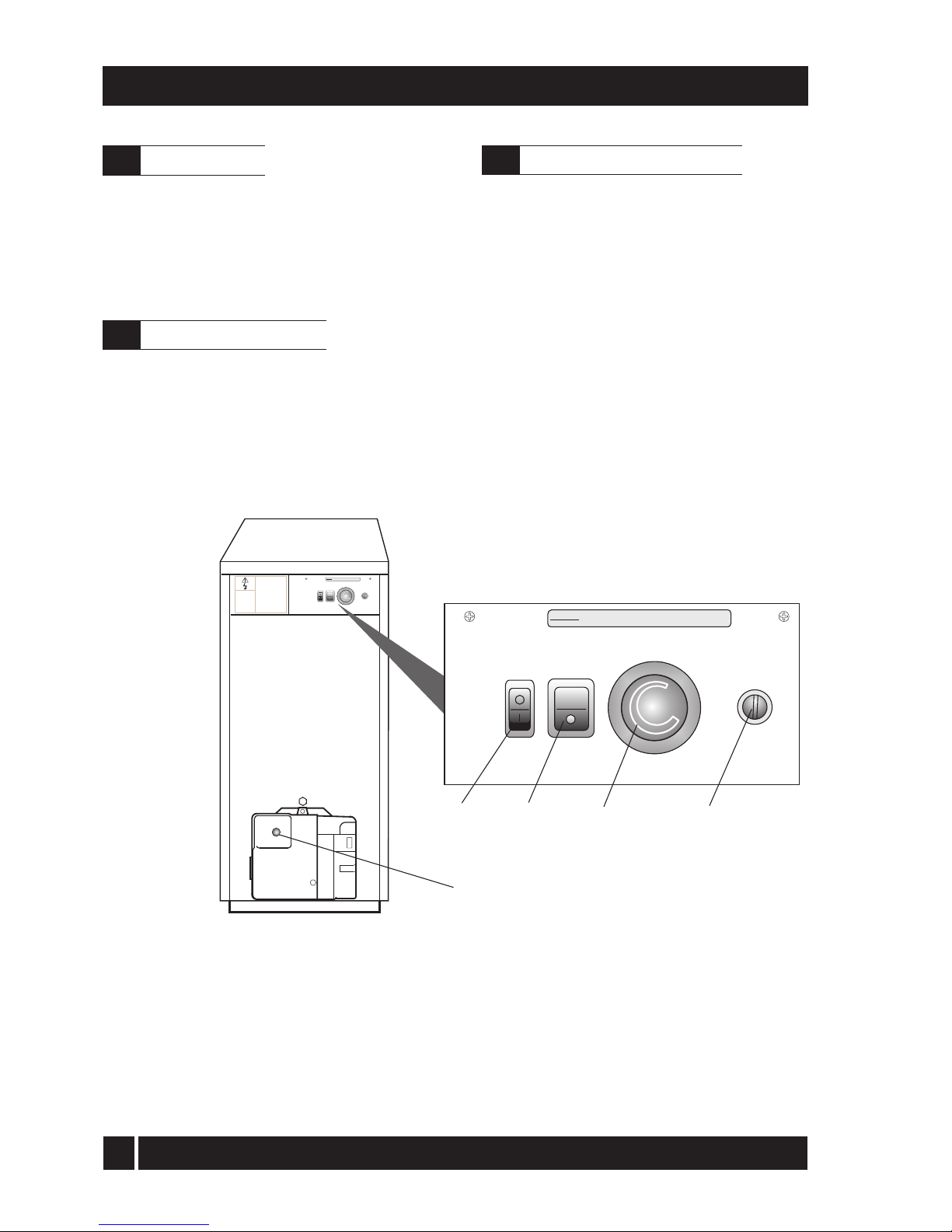
An illuminated On/Off switch, see Fig. A, is fitted to the
External modules, which lights when the boiler is switched
on, but does not necessarily indicate the burner is firing.
To access the External module controls, remove the front
panel by turning the handle and withdrawing it forwards
at the bottom.
Controls for External modules - Fig. A
1 Ensure that - There is sufficient fuel, of the correct
type, in the supply tank and all fuel supply valves are
open. The water supply is on. The electricity supply
to the boiler is off. The Boiler On/Off switch is set to
off (the neon in the switch is not alight). The Test
switch is set to Off. The room thermostat (if fitted) is
at the desired setting. The boiler thermostat is set to
the required setting.
2 Switch on the electricity supply to the boiler.
3 Set the Boiler On/Off switch to on. A neon in the
switch lights when it is in the on position.
The boiler will now light automatically.
About your boiler
2.1
Boiler controls (see Fig. A)
2.2
Lighting your boiler (see Fig. A)
2.3
BOILER ON/OFF SWITCH
ISOLATES PUMP(IF WIRED
INTO BOILER CONTROL
PANEL) & BURNER ONLY.
THIS COVER ISTO BE
REMOVED BYQUALIFIED
PERSONNELONLY
DO NOTREMOVE COVER
WITHOUTISOLATING
SWITCHED LIVEAND
FROST'STAT
PERMANENTLIVE
TESTSWITCH
OVERIDES SYSTEM
CONTROLSTO
OPERATE BOILER
‘Lock-out’ reset button
Boiler front
panel removed
Control Panel
DANGER
THERE IS MORE THAN ONE LIVE SUPPLY TO
THIS CONTROL PANEL
BOILER
OFF
OVERHEAT
RESET
TEST
SWITCH
OFF
HEATING
THERMOSTAT
ON ON
REFER TO WIRING DIAGRAM IN MANUAL
Overheat thermostat
reset button
(under screw cover)
Boiler
thermostat
Boiler
On/Off switch
Test
switch
DANGER
THERE IS MORE THAN ONE LIVE SUPPLY TO
THIS CONTROL PANEL
BOILER
OFF
OVERHEAT
RESET
TEST
SWITCH
OFF
HEATING
THERMOSTAT
ON ON
REFER TO WIRING DIAGRAM IN MANUAL

5
Grant Vortex External Module
For short periods - Set the boiler switch to OFF.
To restart, set the switch to ON.
For long periods - Set the boiler switch to OFF. If
required, the fuel supply valve may be closed and the
water and electricity supplies turned off at the mains.
Note: If the electricity, fuel and water supplies are
turned off, the built-in frost thermostat will not
operate.
1 Check that the boiler switch is ON.
2 Check that any remote programmer (if fitted) is
working and is in an 'on' period.
3 Check that all thermostats are set to the desired
setting and are calling for heat.
4 Check if the burner 'Lock-out' reset button (on the
burner) is lit. If it is, press it to start the burner. If
the burner fails to light and goes to 'Lock-out'
again, check that you have sufficient fuel in the
storage tank and that the fuel supply valve is open.
Check that the fire valve in the oil supply line has not
tripped.
5 Ensure that a fuse has not blown or that the
electricity supply has not failed.
6 Check to see if the safety thermostat has operated
(see Section 2.7).
If the burner still fails to light after carrying out these
checks then a fault exists. Switch off the electricity
supply to the boiler and contact your Service engineer.
Grant Vortex External modules operate on Class C2
Kerosene only. You should always quote this type of fuel
when ordering from your supplier.
Do not wait until the fuel runs out before you order
some more. Sludge in the bottom of the tank may be
drawn into the fuel lines. If it is possible, switch off the
boiler when the new supply is delivered and leave the
fuel to settle for an hour before restarting the boiler.
1 Boiler thermostat - This control allows the
temperature of the water leaving the boiler to heat
the radiators and domestic hot water to be adjusted.
Note: If you have a cylinder thermostat on your hot
water cylinder, this will control the temperature of
your domestic hot water. The boiler thermostat
setting must be equal to or above the cylinder
thermostat setting to enable the cylinder thermostat
to control the domestic hot water system.
2 Burner Lock-out reset button - If there is a
burner malfunction, a built-in safety circuit
switches the burner off and the 'Lock-out' reset
button (on the burner) will light. Usually such
malfunctions are short lived and pressing the reset
button will restore normal operation.
If the burner continually goes to 'Lock-out' a fault
exists or the fuel supply is low. If you have
sufficient fuel, you will need to call your Service
engineer.
3 Safety thermostat - Your boiler is fitted with a
safety overheat thermostat which will automatically
switch off the boiler in the case of a control
malfunction causing overheating.
If your boiler goes off and you try to light it but
nothing happens and the 'Lock-out' reset button on
the burner is not lit, the overheat thermostat has
probably operated. The boiler will not light until
the thermostat is reset. To reset, unscrew the small
plastic cap (see Fig. A), press the button then
replace the cap.
If this condition continually repeats, contact your
Service engineer.
4 Ventilation - Always ensure that the boiler has
adequate ventilation. Any ventilation openings
must not be obstructed. Periodically check that
they are clear.
Do not attempt to 'box in' the boiler or build a
compartment around.
Do not place any combustible material around or
on the boiler or flue pipe.
Do not place anything against the door of the
External modules that might obstruct the
ventilation openings.
5 Flue terminal - The flue terminal must not be
obstructed or damaged.
In severe conditions check that the terminal does
not become blocked by snow.
2 - USER INSTRUCTIONS
Turning off your boiler (see Fig. A)
2.4
Points to check if burner fails to light
2.5
About your fuel
2.6
General notes and care of your system
2.7

6
Grant Vortex External Module
6 Frost protection - Your Installer may have fitted a
frost thermostat. If not, and you are likely to be
away for a short time, leave the boiler on with the
boiler thermostat set at a low setting. For longer
periods the boiler and system should be drained.
Contact your Service engineer for draining and
filling the system.
The control panel of the External modules includes
a built-in frost thermostat factory set to 5°C.
Note: For Vortex External modules we recommend
that a combined antifreeze and corrosion inhibitor
be used in the primary water system.
7 Cleaning and servicing - Lightly wipe over the
case with a damp cloth and a little detergent. Do
not use abrasive pads or cleaners.
You must have your boiler serviced at least once a
year to ensure safe and efficient operation. Contact
your Service engineer for further details.
Warning note - External equipment operated at
230 volts should not be serviced or repaired
under adverse weather conditions.
8 Failure of electricity supply - If the electricity
supply fails, the boiler will not operate. It should
relight automatically when the supply is restored.
The boiler requires a 230/240 V ~ 50 Hz supply. It
must be protected by a 5 Amp fuse.
Warning: This appliance must be earthed.
If your boiler is operating on a sealed heating system,
the installer will have pressurised the system and
should have told you (or set it on the pressure gauge)
the system pressure when cold (this is normally
between 0.5 and 1.0 bar, which will increase slightly
when hot). If the pressure (when cold) is below the set
pressure mentioned above, you can re-pressurise the
system. If the system requires frequent re-pressurising,
ask your Installer or Service engineer to check the
heating system for leaks and to check the expansion
vessel air charge.
An automatic filling system should not be used on a
sealed central heating system.
The boiler or system will be fitted with an automatic
air vent to remove air from the system. Any air trapped
in the radiators should be removed by venting the
radiators using the vent screw at the top of each
radiator. Only vent a radiator if the top is cool and the
bottom is hot. Excessive venting will reduce the
system pressure, so only vent when necessary and
check the system pressure as mentioned above. Repressurise the system if necessary.
The boiler or system may be fitted with a safety valve
to release excess pressure from the system. If water or
steam is emitted from the end of the safety valve
discharge pipe, switch off the boiler and contact your
Installer or Service engineer.
The expansion vessel air charge must be checked
annually. Failure to maintain an adequate air
charge in the vessel may invalidate the warranty.
To re-pressurise the system by adding water:
1 Only add water to the system when it is cold and
the boiler is off. Do not overfill.
2 Ensure the flexible filling loop (see Fig. B) is
connected and that the shut off valve connecting it
to the boiler is open and the double check valve at
the front is closed.
A valve is open when the operating lever is in line with
the valve, and closed when it is at right angles to it.
3 Gradually open the double check valve on the front
of the filling loop until water is heard to flow.
4 Vent each radiator in turn, starting with the lowest
one in the system, to remove air.
5 Continue to fill the system until the pressure gauge
indicates between 0.5 and 1.0 bar. Close the fill
point valve.
6 Repeat steps 4 and 5 as required.
7 Close the valves either side of the filling loop and
disconnect the loop.
2 - USER INSTRUCTIONS
Electricity supply
2.8
Sealed central heating system
2.9
Sealed system filling loop arrangement - Fig. B

7
Grant Vortex External Module
120/155
21
4.7
174
46
157,000
28 mm
28 mm
26.0 mbar
9.5 mbar
4.2 Amp
Boiler technical data
3.1
3 - BOILER TECHNICAL INFORMATION
Model
Water content litre
gal
* Weight (dry) kg
Max. heat output kW
(kerosene) Btu/h
Flow connection
Return connection
Condensate connection
Waterside resistance
Flow/Return temp. diff. of 10°C
Flow/Return temp. diff. of 20°C
Maximum static head
Minimum circulating head
Boiler thermostat range
Limit (safety) stat shut off temp
Max. hearth temperature
Electricity supply
Motor power
Starting current
Running current
Oil connection
Max operating press - sealed sys
Max operating press - open sys
* Weight includes burner but excludes flue.
Vortex External Module
50/90
19
4.2
157
26
88,700
22 mm
22 mm
28.5 mbar
10.0 mbar
2.6 Amp
50/70
16.5
3.6
99
21
71,650
22 mm
22 mm
28.5 mbar
10.0 mbar
4.2 Amp
200/240
50
11
339
70
238,840
1¼" BSP
1¼" BSP
26.0 mbar
9.5 mbar
150 W max.
6.4 Amp
155/200
50
11
335
58
197,876
1¼" BSP
1¼" BSP
26.0 mbar
9.5 mbar
150 W max.
6.4 Amp
90/120
21
4.7
174
36
122,840
28 mm
28 mm
26.0 mbar
9.5 mbar
2.6 Amp
90 W max.
21.5 mm plastic overflow pipe
28 m
1m
65 to 75°C
111°C ± 3°C
Less than 50°C
230/240 V ~ 50 Hz Fused at 5 Amp
0.85 Amp
¼" BSP Male (on end of flexible fuel hose)
2.5 bar
2.5 bar

8
Grant Vortex External Module
3 - BOILER TECHNICAL INFORMATION
Note: Grant Vortex External modules are only for use with kerosene.
Grant Vortex External modules using Class C2 kerosene
3.3
Sealed system data - none available for 155/200, 200/240
3.2
Notes:
1 The data given above is approximate only.
2 The above settings may have to be adjusted on site for the correct operation of the burner.
3 Gas Oil is not suitable for use with the Grant Vortex boiler range.
4 The net flue gas temperatures given above are ± 10%.
5 When commissioning the air damper must be adjusted to obtain the correct CO2 level.
6 * Factory settings.
7 The combustion door test point may be used for CO2 and smoke readings only. Do not use this test point for temperature or efficiency readings.
8 When setting the 50/90 to 51,200 or 68,240 Btu/h output or the 120/155 to 123,000 Btu/h output the combustion head must be changed. Refer to Section
7 Commissioning.
When setting the 50/70 to 51,200 Btu/h output the burner air adjuster disc requires repositioning. Refer to Section 9.4 Cleaning the burner.
9 The installer must amend the boiler data label if the output is changed.
Flue gas analysis
To allow the boiler to be commissioned and serviced, the boiler is supplied with a combustion test point on the front cleaning door. When this test point is
used please note the following:
1. The test point is for CO2 and smoke readings only.
2. The boiler efficiency and temperature must be taken from the flue test point on high level and vertical flue adaptors.
3. Low level flues do not contain a test point. The temperature and efficiency readings must be taken from the flue terminal.
(kW)
15.0
18.3
21.0
15.0
20.0
23.0
26.0
26.0
31.5
36.0
36.0
41.5
46.0
46.0
52.0
58.0
58.0
64.0
70.0
(Btu/h)
51,200
62,400
71,650
51,200
68,240
78,500
88,700
88,700
107,500
123,000
123,000
141,600
157,000
156,952
177,424
197,896
197,896
218,368
238,840
Nozzle
0.50/80°EH
0.55/80°EH
0.60/80°EH
0.50/80°EH
0.60/80°EH
0.65/80°EH
0.75/80°EH
0.75/80°EH
0.85/80°EH
1.00/80°EH
1.00/80°EH
1.20/80°S
1.25/80°S
1.25/80°S
1.35/80°S
1.65/80°S
1.65/80°S
1.65/80°S
1.75/80°S
Oil
press.
(bar)
7.0
7.5
9.0
7.0
8.0
8.5
8.0
8.0
9.0
9.1
9.0
8.0
8.0
8.0
9.5
8.0
8.0
9.5
9.5
Smoke
No.
0 - 1
0 - 1
0 - 1
0 - 1
0 - 1
0 - 1
0 - 1
0 - 1
0 - 1
0 - 1
0 - 1
0 - 1
0 - 1
0 - 1
0 - 1
0 - 1
0 - 1
0 - 1
0 - 1
Fuel flow
rate
(kg/h)
1.29
1.56
1.83
1.25
1.67
1.94
2.18
2.18
2.57
3.01
3.01
3.56
3.90
4.01
4.47
5.05
5.05
5.58
6.01
Flue gas
temp.
(°C)
66
73
80
60 - 65
65 - 70
70 - 75
68
68
70
78
78
80
88
75 - 80
75 - 80
75 - 80
75 - 80
75 - 80
75 - 80
CO
2
(%)
12.0
12.0
12.0
12.0
12.0
12.0
12.0
12.0
12.0
12.0
12.0
12.0
12.0
12.0
12.0
12.0
12.0
12.0
12.0
Burner
head type
T1
T1
T1
T1
T1
T2
T2
T3
T3
T3
T3
T5
T5
GIB
GIB
GIB
GIB
GIB
GIB
Heat Output
50/70
Riello RDB2.2
50/90
Riello RDB1
90/120
Riello RDB2
120/155
Riello RDB2.2
155/200
Riello RDB3.2
200/240
Riello RDB3.2
Model and
burner type
*
*
*
HARP/SEDBUK
efficiency
(%)
93
94 - 95
97
92.62
94.1
93.6
*
Air disc
position
B
C
C
-
-
-
-
-
-
-
-
-
-
-
-
-
-
-
-
*
*
Maximum 1.0 bar, Minimum 0.5 bar
2.5 bar
15 mm copper pipe
15 mm copper pipe
Model
Heating system pressure (cold)
Operating pressure of pressure relief valve
Expansion vessel size (approximately)
Max heating system volume (including boiler)
Cold water mains connection
Pressure relief valve discharge connection
Circulating pump head
50/70
10 litres
106 litres
6 m
50/90
12 litres
128 litres
6 m
90/120 and 120/155
16 litres
170 litres
7 m
Burner
head setting
Fixed
Fixed
Fixed
Fixed
Fixed
Fixed
Fixed
Fixed
Fixed
Fixed
Fixed
Fixed
Fixed
0
0
0
0
0
4
9
Grant Vortex External Module
3 - BOILER TECHNICAL INFORMATION
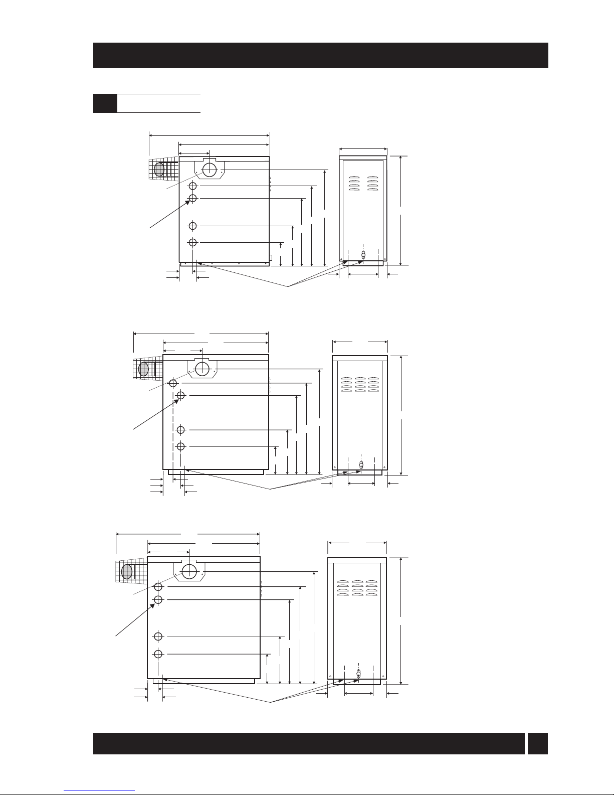
Boiler dimensions
3.4
Fig 1b - 50/90, 90/120 and
120/155dimensions
Fig 1c - 155/200 and 200/240
dimensions
Fig 1a - 50/70
dimensions
4 holes
50mm dia.
in sides
covered with
movable plates
both
879
=
244
=
637
768
517
307
187
99
112
Side flue exit
if required
385
943
734
248
3 holes 50 mm dia.in base of boiler
enclosure covered with movable plates
4 holes
50mm dia.
in sides
covered with
movable plates
both
1154
587
945
233
68
50
1000
1154
816
418
179
1240
=
382
=
Side flue exit
if required
3 holes 50 mm dia.in base of boiler
enclosure covered with movable plates
4 holes
50mm dia.
in sides
covered with
movable plates
both
1005
505
800
269
908
=
320
=
117
132
50
756
A
698
417
192
Side flue exit
if required
3 holes 50 mm dia.in base of boiler
enclosure covered with movable plates
50/90 A = 815
90/120, 120/155 A = 825

10
Grant Vortex External Module
Grant Vortex External Modules have an insulated
weatherproof enclosure made of galvanised steel, and
are designed for external installation, either against a
wall or free standing some distance away from the
property, as required. For flue clearances see page 15.
The Vortex External modules are part of the Grant range
of automatic pressure jet oil boilers have been designed
for use with a fully pumped central heating system with
indirect domestic hot water cylinder. They are not suitable
for use with either a direct cylinder or a 'primatic' cylinder
or gravity hot water..
The boilers are suitable for use on open vented or
sealed central heating systems.
All models are supplied with the control panel and
burner factory fitted.
The factory fitted low level discharge flue system can
be adjusted on site for either rear, left hand or right
hand flue outlet position, as required.
An external Plume Diverter kit (Fig. 16) is also available
from your local stockist. Refer to Section 6.4 for further
details.
All burners are pre-set for use with kerosene and are
supplied ready to connect to a single pipe fuel supply
system with a loose flexible fuel line and
3
/8" to 1/4" BSP
male adaptor supplied with the boiler.
If required, an additional flexible fuel line (600 mm) and
3
/8" to 1/4" BSP male adaptor are available to purchase
from your local stockist, for two-pipe oil supply systems.
The temperature of the water leaving the boiler to heat
the radiators and hot water cylinder is User adjustable.
The boiler is fitted with an overheat thermostat (which
allows it to be used on a sealed central heating system)
which will automatically switch off the boiler if the heat
exchanger exceeds a pre-set temperature of 111°C ± 3°C.
The control panel is fitted with an ON/OFF switch,
boiler thermostat control knob and the manual reset
button for the overheat thermostat
Boiler description
4.1
Boiler components
4.2
4 - GENERAL BOILER INFORMATION
Installation of a Grant Vortex boiler must be in
accordance with the following recommendations:-
a Local Building Regulations, and Building
Standards issued by the Department of the
Environment and any local Byelaws etc.
b Model and local Water Undertaking Byelaws.
c Applicable Control of Pollution Regulations.
d The following OFTEC requirements:-
OFST 100 Polythene oil storage tanks for
distillate fuels.
OFST 200 Fuel oil storage tanks and tank
bunds for use with distillate fuels,
lubrication oils and waste oils.
Further information may be obtained from the
OFTEC Technical Information Book 3
(Installation requirements for oil fired boilers
and oil storage tanks).
The installation should also be in accordance with the
latest edition of the following British Standard Codes
of Practice:-
BS 715 Metal flue pipes, fittings, terminals
and accessories.
BS 799:5 Oil storage tanks.
BS 1181 Clay flue linings and flue terminals.
BS 4543:3 Factory made insulated chimneys for
oil fired appliances.
BS 4876 Performance requirements for oil
burning appliances.
BS 5410:1 Code of Practice for oil firing appliances.
BS 5449 Forced circulation hot water systems.
BS 7593 Code of Practice for treatment of
water in heating systems.
BS 7671 Requirements for electrical
installations, IEE Wiring Regulations.
Failure to install and commission appliances
correctly may invalidate the boiler warranty.
IMPORTANT
Before starting any work on the boiler, or fuel supply
please read the health and safety information given in
Section 14 on page 43.
Regulations to comply with
4.3

11
Grant Vortex External Module
4 - GENERAL BOILER INFORMATION
4 A metal bowl type filter with a replaceable
micronic filter must be fitted in the fuel supply line
adjacent to the boiler. A shut-off valve should be
fitted before the filter, to allow the filter to be
serviced.
5 A flexible fuel hose, adaptor and 1/4" BSP isolation
valve are supplied loose with the boiler for the final
connection to the burner. If a two pipe system or
'Tiger Loop' type de-aerator is used, an additional
flexible fuel hose (600 mm) and 3/8" to 1/4" BSP male
adaptor are available to purchase from your local
stockist. If a 'Tiger Loop' is fitted it should not be
fitted indoors or within a boiler casing.
6 Metal braided flexible hoses should be replaced
annually when the boiler is serviced. Long life
flexible hoses should be inspected annually and
replaced at least every 60 months.
4.4.3 Single pipe system - (See Fig. 2)
1 Where the storage tank outlet is above the burner
the single pipe system should be used. The height
of the tank above the burner limits the length of
pipe run from the tank to the burner.
2 As supplied the burner is suitable for a single pipe
system.
4.4.1 Fuel storage
The tank should be positioned in accordance with the
recommendations given in BS 5410:1:1997, which gives
details of filling, maintenance and protection from fire.
A steel tank may be used and must be constructed to
BS 799:5:1987 and OFST 200.
A galvanised tank must not be used.
A plastic tank may be used and must comply with
OFST 100.
Note: Plastic tanks should be adequately and
uniformly supported on a smooth level surface, across
their entire base area.
4.4.2 Fuel pipes
1 Fuel supply pipes should be of copper tubing with
an external diameter of at least 10 mm.
Galvanised pipe must not be used.
All pipe connections should preferably use flared
fittings. Soldered connections must not be used on
oil pipes.
2 Flexible hoses must not be used outside the boiler case.
3 A remote sensing fire valve (not a fusible head type)
must be installed in the fuel supply line, with the
sensing head located above the burner.
Recommendations are given in BS 5410:1:1997.
Fuel supply
4.4
Regional statutory requirements may deem this appliance to be a 'controlled service'.
Where this is the case, it is a legal requirement that the appliance is installed and
commissioned either under the remit of building control or by a 'Competent person' such
as a suitably qualified Oftec registered technician.
Fig. 2 - Single pipe system
Filter
Fire
valve
Shut-off
valve
Shut-off
valve
A
Sludge
valve
Fill
pipe
Vent
pipe
Level
gauge
Fuel
storage
tank
Head A
(m)
Maximum pipe run (m)
0.5
1.0
1.5
2.0
10 mm OD pipe
10
20
40
60
12 mm 0D pipe
20
40
80
100
Fire
valve
sensor
Pump
1m

12
Grant Vortex External Module
4.4.5 Tiger Loop system - (See Figs. 4 and 5)
1 When the storage tank is below the burner, an
alternative to a two pipe system can be achieved
using the 'Tiger Loop' type oil deaerator. This
effectively removes the air from the oil supply on a
single pipe lift.
2 The de-aerator is connected close to the boiler as a
two pipe system (omitting the non-return valve) as
shown in Fig. 4. Refer to the manufacturers
instructions supplied with the de-aerator.
The de-aerator must be mounted vertically and
externally.
3 To be used with a de-aerator, the burner must be
fitted with an additional flexible fuel hose (a flexible
fuel hose (600 mm) and 3/8" to 1/4" BSP male adaptor
are available to purchase from your local stockist. See
Section 4.4.6.
4.4.4 Two pipe system - (See Fig. 3)
1 When the storage tank outlet is below the burner,
the two pipe system should be used. The pipe runs
should be as shown in Fig. 3. The return pipe
should be at the same level in the tank as the
supply pipe, both being 75 to 100 mm above the
base of the tank. The pipe ends should be a
sufficient distance apart so as to prevent any
sediment disturbed by the return entering the
supply pipe.
2 Avoid the bottom of the tank being more than 3 m
below the burner.
3 A non-return valve should be fitted in the supply
pipe together with the filter and fire valve. A nonreturn valve should be fitted in the return pipe if
the top of the tank is above the burner.
4 To be used with a two-pipe system, the burner
must be fitted with an additional flexible fuel hose
(a flexible fuel hose (600 mm) and 3/8" to 1/4" BSP
male adaptor are available to purchase from your
local stockist.
5 The pump vacuum should not exceed 0.4 bar.
Beyond this limit gas is released from the oil.
For guidance on installation of top outlet fuel tanks and
suction oil supply sizing, see OFTEC booklet T1/139.
Available at www.oftec.org.uk
4 - GENERAL BOILER INFORMATION
Fig. 3 - Two pipe system
Filter
Fire
valve
Shut-off
valve
Shut-off
valve
See
section 4.4.6
A
Return
Supply
Head A
(m)
Maximum pipe run (m)
0
0.5
1.0
1.5
2.0
3.0
3.5
10 mm OD pipe
35
30
25
20
15
8
6
12 mm OD pipe
100
100
100
90
70
30
20
Non
return
valve
Fire
valve
sensor
Sludge
valve
Fill
pipe
Vent
pipe
Level
gauge
Fuel
storage
tank
1m

13
Grant Vortex External Module
4 - GENERAL BOILER INFORMATION
4.4.6 Two pipe oil supplies
Riello RDB burner - See Fig. 6
1 The fuel pump is supplied for use with a single
pipe fuel supply system. For use on a two pipe
system, it is necessary to fit the By-pass screw (see
Fig. 6) into the tapping in the return port.
2 The By-pass screw is supplied in the boiler
accessory pack.
3 Remove the plastic burner cover (two screws).
4 Remove and discard the blanking plug from the
return connection of the pump and fit the By-pass
screw using an hexagonal key.
5 Connect the return oil flexible fuel hose to the pump.
6 Connect the 3/8" to 1/4" BSP adaptor to the flexible
fuel hose.
Fig. 4 - De-aeration device system
Fig. 5 - Tiger loop 'de-aeration' device
Fig. 6 - Riello RDB pump
1 Oil inlet connection
2 Return connection
3 By-pass screw
4 Pressure gauge connection
5 Pressure adjuster
6 Vacuum gauge connection
7 Solenoid
8 Supply to nozzle
1
2
3
4
5
6
7
8
1/4" BSP female
connections
Tiger Loop
SUPPLY
TO PUMP
RETURN
FROM PUMP
SUPPLY
FROM TANK
Fire valve
Tankmaster
See
section 4.4.6
Sludge
valve
Fill
pipe
Vent
pipe
Fuel
storage
tank
De-aeration device
e.g. Tiger Loop
See Fig. 5
Fire
valve
sensor
Supply
1m
Return

14
Grant Vortex External Module
1 A 230/240 V ~ 50 Hz mains supply is required.
The boiler must be earthed.
2 The supply must be fused at 5 Amp and there must
only be one common isolator for the boiler and
control system, providing complete electrical
isolation.
3 A fused double pole switch or a fused three pin
plug and shuttered outlet socket should be used for
the connection.
4 The power supply cable should be at least 0.75 mm²
PVC as specified in BS 6500, Table 16.
5 All the wiring and supplementary earth bonding
external to the boiler must be in accordance with
the current I.E.E. Wiring Regulations.
6 Any room thermostat or frost thermostat used must
be suitable for use on mains voltage.
7 The boiler requires a permanent mains supply, do
not interrupt it with any external time control.
8 In the event of an electrical fault after installation
of the boiler, the following electrical system checks
must be carried out:- Short circuit, Polarity, Earth
continuity and Resistance to earth.
1 External Modules are supplied with a factory fitted
frost protection thermostat, located inside the
boiler control panel. This is pre-wired to the boiler
electrical system and factory set to 5°C.
2 For total system protection against freezing,
particularly during extended periods without
electrical power, Grant recommend the use of a
combined heating system antifreeze and corrosion
inhibitor, used in accordance with the
manufacturer's instructions.
4 - GENERAL BOILER INFORMATION
1 The External Module must stand on a solid, level
surface capable of supporting the weight of the boiler
when full of water, e.g. a prepared concrete standing,
paving slabs bedded down on sand/cement, or similar.
2 The Module can be installed either against the building
or 'free standing' some distance away from the building.
3 The Module must be positioned such that the
required clearances from the low level flue outlet,
as shown in Fig. 7, are achieved.
4 Adequate clearance must be left around the Module
for servicing. In particular, a minimum clearance of
600 mm above the Module for removal of the top
panel and 600 mm at the opposite end to the flue outlet
for access to the burner.
Sufficient clearance is required at the rear of the
boiler to allow the rear panel to be removed for
access to the condensate trap.
5 The flue terminal must be a minimum distance of
1.8 m from an oil storage tank.
The flue terminal should be positioned so as to
avoid products of combustion accumulating in
stagnant pockets around the building or entering
into buildings.
Electricity supply
4.5
Frost protection
4.6
Boiler location
4.7
 Loading...