

Grant TXF200 Operating Manual [en, de, es, fr, it]
FR
EN
DE
IT
ES
Precision immersion
thermostats, baths &
circulators
Optima TX150 & TXF200
Operating Manual

Grant Instruments, based near Cambridge, England is a world leader in the
manufacture and design of equipment for sample preparation, scientific analysis, data
acquisition and data analysis providing solutions to the global scientific and industrial
markets.
Standards Compliance and Quality
Grants’ brand and reputation are based around quality, reliability and accuracy. We
ensure our products stringently meet all necessary international safety standards.
We pay particular attention to the safety testing of products and remain at the forefront of
the product safety standard for laboratory equipment IEC 61010-1. The company is
committed to operating its safety test laboratory in accordance with the requirements of
ISO 17025.
Grant operates a Quality Management System that complies with the requirements of BS
EN ISO 9001:2008.
Beyond compliance to the standard, Grant is committed to continually improving in
everything we do; with particular emphasis on understanding what matters to our
customers and suppliers, and designing our systems and work to meet their needs.
If you have any feedback on Grant’s products or services we would like to hear from you.
Please send all feedback to:
Quality Manager
Grant Instruments (Cambridge) Ltd
Shepreth
Cambridgeshire
SG8 6GB
UK
Tel: +44 (0) 1763 260 811
Fax: +44 (0) 1763 262 410
E-mail: feedback@grantinstruments.com

EN
Contents
Contents 2
1.0 Use of products 4
2.0 How to use this operating manual 4
3.0 Safety information 5
3.1 Safety compliance 5
3.2 Safety symbols 5
3.3 Safety warnings 5
4.0 Operating instructions 6
4.1 Unpacking instructions 6
4.2 Fitting controller to ST baths 6
4.3 Fitting the controller to P baths 7
4.4 Fitting the controller to custom baths 7
4.5 Removing the controller from the bridge plate 8
4.6 Recommended liquids 8
4.7 Installation 9
4.8 Electrical supply 9
4.9 Using accessory cooling (C1G, C2G, CW5) 9
5.0 Operating procedures 10
5.1 Operation 10
5.1.1 Liquid level 10
5.1.2 Operation above 60°C 10
5.1.3 Operation at low temperatures 10
5.1.4 Using the pump 10
5.1.5 Using the switch over relay output 11
5.1.6 Emptying the ST baths 12
5.1.7 Setting up and switching on 12
5.1.8 Power loss 12
5.2 Using the TX150 & TXF200 13
5.2.1 Front panel controls 13
5.2.2 Rear panel connections 14
5.2.3 Communications ports 14
5.2.4 Switched relay port 14
5.2.5 External probe input 14
5.2.6 Setting the over-temperature thermostat 15
5.2.7 Display. Explanation of home screen icons. 15
5.2.8 Description of user interface and controls 16
5.2.9 Setting the control temperature 16
5.2.10 Setting a pump speed (TXF200 only) 16
5.2.11 Running a bath preset 17
5.2.12 Running a countdown timer 17
5.2.13 Running a program 18
5.2.14 Activating standby mode 19
5.2.15 Accessing the settings menu 19
5.3 Viewing, editing and saving settings 21
5.3.1 Configuring a preset 21
5.3.2 Creating a program (TXF200 only) 22
5.3.3 Editing a program (TXF200 only) 24
5.3.4 Selecting a liquid type 25
5.3.5 Selecting a temperature probe type 26
5.3.6 Configuring high and low temperature alarms 27
5.3.7 Setting the buzzer volume level 30
5.3.8 Selecting a language 30
5.3.9 Relay test and configuration 31
5.3.10 Display rounding 32
TX150 & TXF200 30424 V6
Operating Manual Page 2
www.grantinstruments.com

5.4 Completing a calibration 33
5.4.1 Restoring factory calibration settings 34
6.0 Technical specifications 35
6.1 Operating conditions 35
6.2 Electrical details 35
6.3 Product performance 35
6.4 Bath accessories information 35
7.0 Technical Tips 36
7.1 Which water should you use in your bath? 36
7.2 How to prevent rust in water baths 36
7.3 How to prevent algae and bacteria 37
8.0 Warranty information 37
9.0 Maintenance and service 37
9.1 Routine maintenance 37
9.2 Cleaning 37
9.3 Fuses 38
9.4 Replacing the mains cord 38
9.5 Routine safety tests 38
9.6 Service 38
10.0 Optional accessories 38
11.0 Troubleshooting 39
12.0 Contact Grant Instruments 42
13.0 Compliance 42
30424 V6 TX150 & TXF200
Page 3 Operating Manual
www.grantinstruments.com

EN
1.0 Use of products
The following products are covered by this operating manual:
TX150 & TX150L
TXF200 & TXF200L
The products listed above are precision immersion thermostats to be used with baths or
circulators designed for indoor laboratory use by a professional user.
2.0 How to use this operating manual
This operating manual will allow you to unpack, set-up and operate this immersion
thermostat correctly and safely. Important safety information, symbols and warnings are
listed below and should be read carefully. Section 4 gives information about how to
unpack and install the product correctly. Section 5 gives operating information for the
TX150 & TXF200 models. Product technical specifications and tips are provided in
sections 6 and 7. The warranty for this product is for THREE YEARS and is detailed in
section 8 and should be registered by completing the on-line registration form at
www.grantinstruments.com.
If there is a technical matter that this operating manual does not address, or any other
question concerning this product, please contact Grant Instruments or your local
distributor, who will be able to provide any additional information.
TX150 & TXF200 30424 V6
Operating Manual Page 4
www.grantinstruments.com
3.0 Safety information
Caution: Surfaces and heat transfer liquid can be hot during and after use.
Read this manual before using the bath.
Important safety warning.
Read the whole of these instructions. Safety may be impaired if they are not
followed.
For the TX150/TXF200 only use liquids specified in these operating instructions,
within the specified temperature range. Do not inhale the vapours given off as
they may be toxic. Liquids should be safely discarded and replaced.
Do not use the TX150/TXF200 with flammable heat transfer liquids.
Do not use the TX150/TXF200 to heat any sample material that could cause a
fire or any other kind of hazard.
Do not use the equipment in an area where there are aggressive or explosive
chemical mixtures.
If a potentially hazardous liquid is spilt onto or inside the equipment, disconnect
it from the power supply and have it checked by a competent person.
It is the user’s responsibility to carry out appropriate decontamination if
hazardous material is spilt on the equipment.
If there is a warning message on the screen, do not touch the liquid or the bath
surfaces, they may be very hot.
Refill carefully, a hot heater can cause a spattering of very hot water droplets
and scalding steam.
Do not touch surfaces which become hot during high temperature operation.
3.1 Safety compliance
Grant immersion thermostats meet the requirements of international safety standard
IEC 61010: Safety requirements for electrical equipment for measurement, control, and
laboratory use. They also comply with the equivalent national standards including:
EN 61010-2-010
UL 61010A-2-010
CAN/CSA-C22.2 NO. 61010-2-010-04.
3.2 Safety symbols
The symbols below are marked on the equipment and throughout this manual to indicate:
3.3 Safety warnings
30424 V6 TX150 & TXF200
Page 5 Operating Manual
www.grantinstruments.com
EN
4.0 Operating instructions
2 A B 1 2
4.1 Unpacking instructions
Standard equipment includes:
Immersion thermostat (TX150 or TXF200)
Pump outlet plates
Mains cord with plug
Operating manual
Quick start guide
ST bath accessory includes:
Stainless steel bath
Bridge plate
Circulating tray (ST18, ST26 & ST38 baths only)
P bath accessory includes:
Plastic bath
Bridge plate
Remove packing materials carefully and retain them for future shipment or storage of the
equipment.
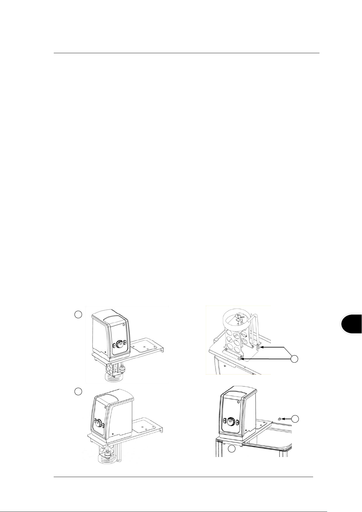
4.2 Fitting controller to ST baths
The TX150/TXF200 can be fitted to the following stainless steel baths, ST5, ST12, ST18,
ST26 and ST38 in two orientations for convenience, facing over ST bath (A) or facing
outwards (B):
1. Fit the TX150/TXF200 through the hole in the bridge plate and align using the
locating threads. Secure using the retaining nuts (1). Hand tighten only.
2. Hook the assembly into the slots on the ST bath and use the supplied fixing to secure
to the rear of the bath (2).
TX150 & TXF200 30424 V6
Operating Manual Page 6
www.grantinstruments.com

Fit the circulation tray in the base of the tank with the large cut out in the tray underneath
Take care not to over tighten the clamp to avoid damaging the clamp or vessel
The liquid container on which the unit is mounted must be stable and have the
necessary robustness, mechanical, chemical and heat resistance.
1 2 1
2
the control unit (ST18, ST26 & ST38 only).
4.3 Fitting the controller to P baths
The TX150/TXF200 can be fitted to the following plastic baths, P5, P12 and P18:
1. Fit the TX150/TXF200 through the hole in the bridge plate and align using the
locating threads. Secure using the retaining nuts (1). Hand tighten only.
2. Add the assembly to the P bath and use the supplied fixing to secure to the rear of
the bath (2).
4.4 Fitting the controller to custom baths
A clamp can be fitted to the TX150/TXF200 to allow attachment to a non-Grant bath or
vessel with a wall thickness of up to 30mm. To fit the clamp to the TX150/TXF200:
1. Place clamp over locating threads on base of TX150/TXF200. Secure using the
retaining nuts. Hand tighten only.
2. Add clamp rear fixings to secure to rear of TX150/TXF200.
Do not wash the clamp in a dishwasher or clean it with descaler. Do not submerse the
threaded shaft of the clamp. Always dry the threaded shaft and clamp after cleaning.
The threads may be lubricated with a small amount of light machine oil.
30424 V6 TX150 & TXF200
Page 7 Operating Manual
www.grantinstruments.com
EN
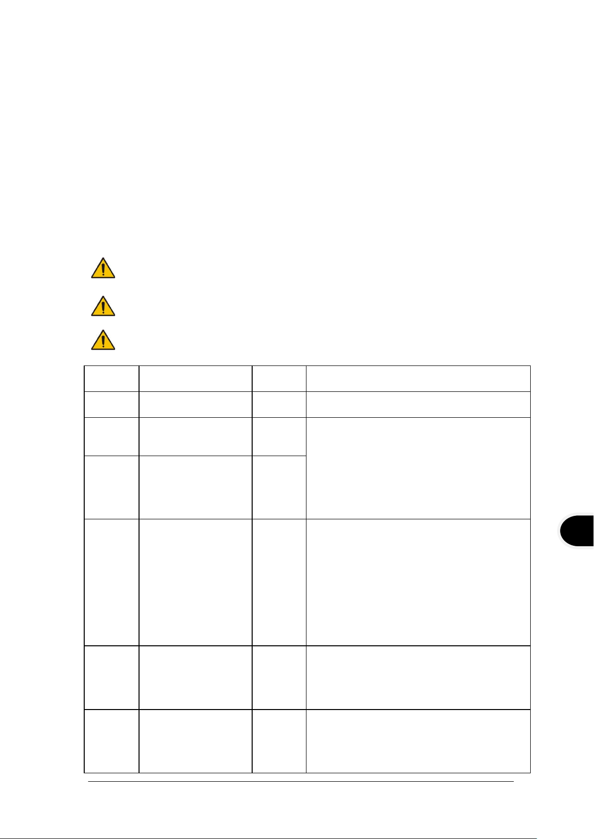
4.5 Removing the controller from the bridge plate
To ensure protection the overtemperature cut-out must be set appropriately for
the heat transfer liquid selected see table.
If using non-recommended heat transfer liquids it is important to set the overtemperature cut-out to a value no higher than 25°C below the fire point of the
liquid. If in doubt please contact the Grant technical support team.
Use fume extraction when using silicone fluids at elevated temperatures
Temp
range
Recommended
liquid
Cut-out
setting
Comments
-50°C to
50°C
Silicone Oil, low
viscosity
60°C
Bayer Silicone M3 is a suitable liquid
-30°C to
70°C
50% water, 50%
antifreeze (inhibited
ethylene glycol)
80°C
WARNING: Ethylene glycol is toxic – follow
the manufacturer’s instructions.
For safe disposal consult your local
regulations.
Use a lid to reduce the dilution of the
mixture caused by condensing water
vapour from the air, and to maintain the
cool down rate.
0°C to
30°C
80% water, 20%
antifreeze (inhibited
ethylene glycol)
40°C
5°C to
99.9°C
Water*
110°C
Water can be used but care should be
taken above 60°C as hot vapour can be
dangerous.
Use a lid or polypropylene spheres above
60°C to ensure good performance & reduce
evaporation.
At temperatures approaching 99°C the
temperature performance will be affected
due to localised boiling.
*The units should not be used to boil water.
70°C to
150°C
Silicone fluid
Viscosity ~20cS
Flash point ≥230°C
Fire Point ≥280°C
160°C
Dow Corning DC200/20 silicone fluid is a
suitable liquid – follow the manufacturer’s
instructions.
For safe disposal consult your local
regulations.
70°C to
200°C
Silicone fluid
Viscosity 50cS
centistokes
Flash point ≥285°C
Fire Point ≥340°C
210°C
Baysilone M 50 EL silicone fluid is a
suitable liquid - follow the manufacturer’s
instructions.
For safe disposal consult your local
regulations.
Allow the working liquid to cool before removing the TX150/TXF200 from the bridge
plate. Carefully remove the TX150/TXF200 and bridge plate together from the bath or
vessel. Take care as the pump will contain a small amount of the working liquid which
will leak out as the unit is handled. Undo the retaining nuts and remove the bridge plate.
Attach the retaining nuts to the locating threads for safe keeping.
4.6 Recommended liquids
The following table lists the recommended liquids for different temperature ranges.
Always ensure the liquid used is safe and suitable for your working temperature. If using
non-recommended heat transfer liquids, it is the responsibility of the user to conduct an
assessment to ensure the intended fluid is compatible with the TX150/TXF200 and
vessel.
TX150 & TXF200 30424 V6
Operating Manual Page 8
www.grantinstruments.com
Temp
range
Recommended
liquid
Cut-out
setting
Comments
-50°C to
150°C or
200°C
None
As
required
for
safety
Override range - The user must select a
suitable safe liquid and carry out their own
risk assessment before use. Note that the
control when using this setting may be
affected as the liquid characteristics are
unknown.
Place the water bath on a level, non-combustible surface. Ensure that the
mains plug and the switch at the rear of the unit are easily accessible.
If the equipment has been transported or stored in cold or humid conditions,
condensation may form inside it. If that could have happened, allow time (at
least 2 hours at room temperature) for the condensation to evaporate before
using the equipment.
Do not block or restrict ventilation slots.
Check that the supply voltage marked on the serial number label, and the type
of mains plug, are correct for your mains supply outlet, which must have an
earth (ground) connector.
The TX150/TXF200 must only be connected to the mains using the mains cord
supplied or one with an identical rating (see section 9.4)
2
1
3
CW5
C1G & C2G
2
1
3
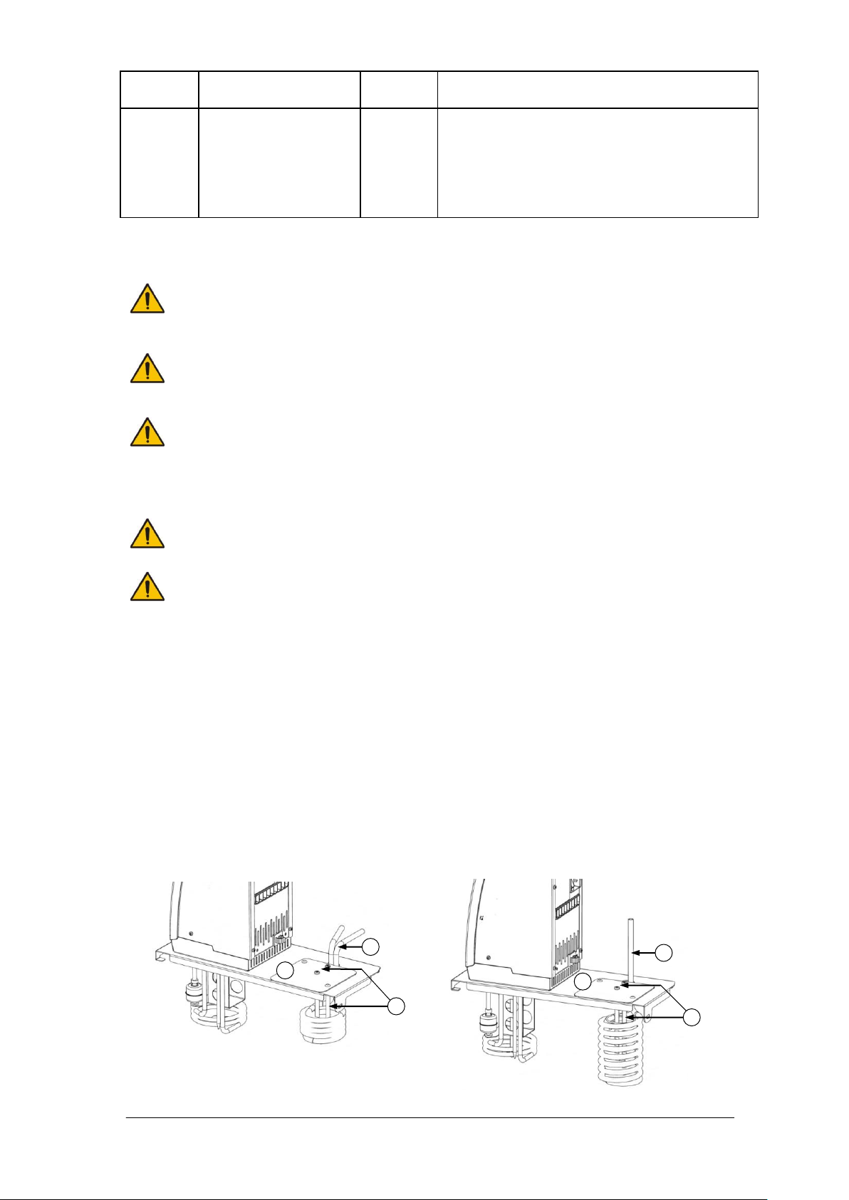
4.7 Installation
4.8 Electrical supply
4.9 Using accessory cooling (C1G, C2G, CW5)
Accessory cooling is required for operation at temperatures below ambient. Refrigerated
dip coolers (C1G and C2G) can be used for operation down to -15°C. A water heat
exchanger coil (CW5) can be used for operation at or around ambient. The coils can be
fitted:
1. Attach u-shaped coil locating rod to cover plate using two fixings supplied (1).
2. Fit the cooling coil through the hole in the bridge plate and align outlet pipes with cutout notch (2).
3. Fit cover plate (3) onto bridge plate and attach with fixings supplied. The coil locating
rod should press fit against the inside of the coil and hold it rigidly. Ensure the coil is
held safely and securely before operation.
30424 V6 TX150 & TXF200
Page 9 Operating Manual
www.grantinstruments.com

EN
5.0 Operating procedures
Take care when lifting and removing the lid as it may be hot. Steam and hot
vapours can cause scalding.
5.1 Operation
5.1.1 Liquid level
The minimum and maximum liquid levels are defined in section 6.4 for Grant accessory
baths. Liquid level should always be maintained between these levels. These levels
apply both when there are no vessels in the bath and with the maximum contents. If
using liquids that can evaporate then periodic checking and refilling should be completed.
The low level float switch will alarm if the liquid level drops below the minimum required
level and the unit will switch off the heater and stop temperature control.
5.1.2 Operation above 60°C
A lid or polypropylene spheres must be used above 60°C to maintain temperature control
and to ensure that the bath fluid temperature reaches the set point. They will save
energy by preventing excessive evaporation and reduce the frequency that the bath
needs to be refilled. As a precaution, the TX150/TXF200 may display ‘Overheatingpower reduced’ if heating water at or near boiling over extended periods or heating large
volumes of liquid with large thermal losses without the use of a lid or polypropylene
spheres. In this event the heating power is reduced by 50%. See section 11 for
additional guidance.
Care should be taken to ensure rear inlet vents are clear and minimise the intake of
steam or fumes when operating at or near water boiling or with other evaporating liquid.
5.1.3 Operation at low temperatures
Accessory cooling is required for controlled operation at or below ambient temperature.
The minimum working temperature without accessory cooling depends on the size of the
bath. The small baths, P5 and ST5, have a minimum working temperature of
approximately 10°C above ambient without a lid and 15°C above ambient with a lid.
Other bath sizes can be used at a temperature of 5°C above ambient.
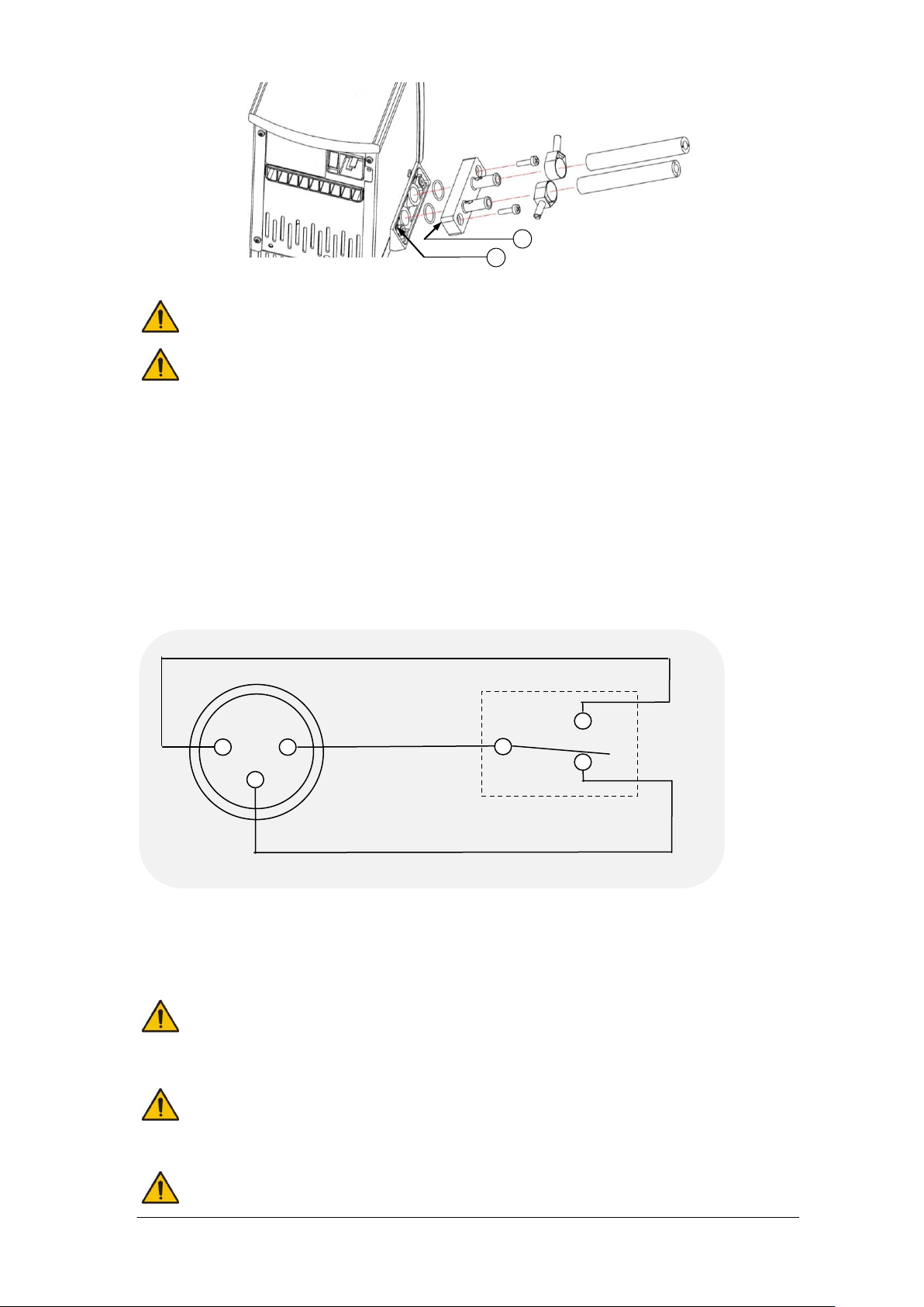
5.1.4 Using the pump
The TX150/TXF200 allows liquid to be pumped around a closed external system (not
open to the atmosphere). It may be used for circulation through an external open tank
only if a gravity feed return is present. An assessment of any open system should be
completed to ensure liquid levels are stable during operation and there is no chance of
any reservoir running dry or overflowing. The pump is fitted with a blanking plate as
standard. Fit a pump connector plate as shown below. Note: the blanking/connector
plates have a locating hole (see A below) to assist correct alignment onto the pump
moulding. It is important to verify the hole is aligned with the corresponding locating pin
(see B below) on the pump moulding. Failure to do so will result in a leaking connection.
Retain the blanking plate for refitting when the pump is no longer required.
TX150 & TXF200 30424 V6
Operating Manual Page 10
www.grantinstruments.com
Always use pump connectors and hoses that are suitable for the operating
temperature and liquid used. Check the pipe connections are secure.
Never disconnect any pipes or hoses while they contain very hot or very cold
liquids or while the TX150/TXF200 is pumping.
The relay is rated 24Vac or dc at 2A; to prevent injury or equipment damage, do
not connect to greater voltages or attempt to switch greater currents.
Voltages as low as 22Vac can be hazardous in locations where wetting of the
skin can occur. When making up cable to connect your equipment to the relay
connector, on the TX150/TXF200, make sure that the insulation system used is
adequate to provide protection against the voltages output by your equipment
for switching by the relay.
Always use the correct size cable with correct class of insulation for the voltage
being switched. If in doubt contact the technical support team at Grant.
3
2
1
Normally Closed
Normally Open
Common
Rear
Panel
connector
Relay
B
A
Pumping heat transfer liquid around an external system can lead to hazards that are
outside the control of Grant Instruments. It is essential that the user conducts a risk
assessment of the entire equipment installation to ensure that correctly rated materials
have been used throughout and that the system can be used safely.
5.1.5 Using the switch over relay output
An internal relay provides switch over contacts that can be used to control external
equipment. The pin connections on the rear panel 3 pin circular connector are:
For the connecting cable use a mating XLR style connector such as the NC3FXX
manufactured by Neutrik AG
The switch over contacts are rated at 24V AC or DC 2A maximum.
30424 V6 TX150 & TXF200
Page 11 Operating Manual
www.grantinstruments.com

EN
5.1.6 Emptying the ST baths
Allow the liquid temperature to fall to a safe level before emptying or moving.
The ST12, ST18, ST26 & ST38 baths should be emptied to a safe level prior to moving.
A drain tap is included on these baths to allow convenient emptying.
CAUTION: if the bath is drained at temperatures above 50°C then the drain mechanism
will be damaged and will need to be replaced. Take reasonable precautions to prevent
accidental spillage.
Empty the bath by pushing the supplied drain insert into the drain tap as shown below.
Note that the bath liquid will begin to empty as soon as the drain insert is fully engaged.
A length of hose can be added to the barbed end of the drain insert if required.
5.1.7 Setting up and switching on
Attach the TX150/TXF200 securely to the required bath or vessel. Add the appropriate
working liquid to the bath to at least the minimum recommended fill level such that the
float level switch is fully raised.
Connect the TX150/TXF200 to a grounded (earthed) electrical power supply with voltage
and frequency within the range specified on the serial number plate.
Switch on the TX150/TXF200 using the power switch on the rear of the unit. The motor
will start immediately and the buzzer will sound while the unit starts up. During start up
the display will show the software version before displaying the home screen. The
TX150/TXF200 is ready to use.
To disconnect the equipment from the mains supply, remove the mains plug from the
mains supply outlet.
5.1.8 Power loss
If power is lost, either due to the unit being switched off or due to a power failure, then
when the power is restored the unit will return to the home screen (see 5.2.7) with the
last valid set temperature and pump speed. Note that, if a program was running (see
5.2.13), the set temperature will be the one set before the program started. If a preset
was in use (see 5.2.11) then the set temperature and pump speed will be correct but the
preset number will not be displayed. The countdown timer (see 5.2.12) will be stopped.
TX150 & TXF200 30424 V6
Operating Manual Page 12
www.grantinstruments.com

5.2 Using the TX150 & TXF200
Over-temperature dial
Full colour display
Select button
Main dial
Float switch
Heater coils
Pump outlet plate
Function button
5.2.1 Front panel controls
30424 V6 TX150 & TXF200
Page 13 Operating Manual
www.grantinstruments.com
EN
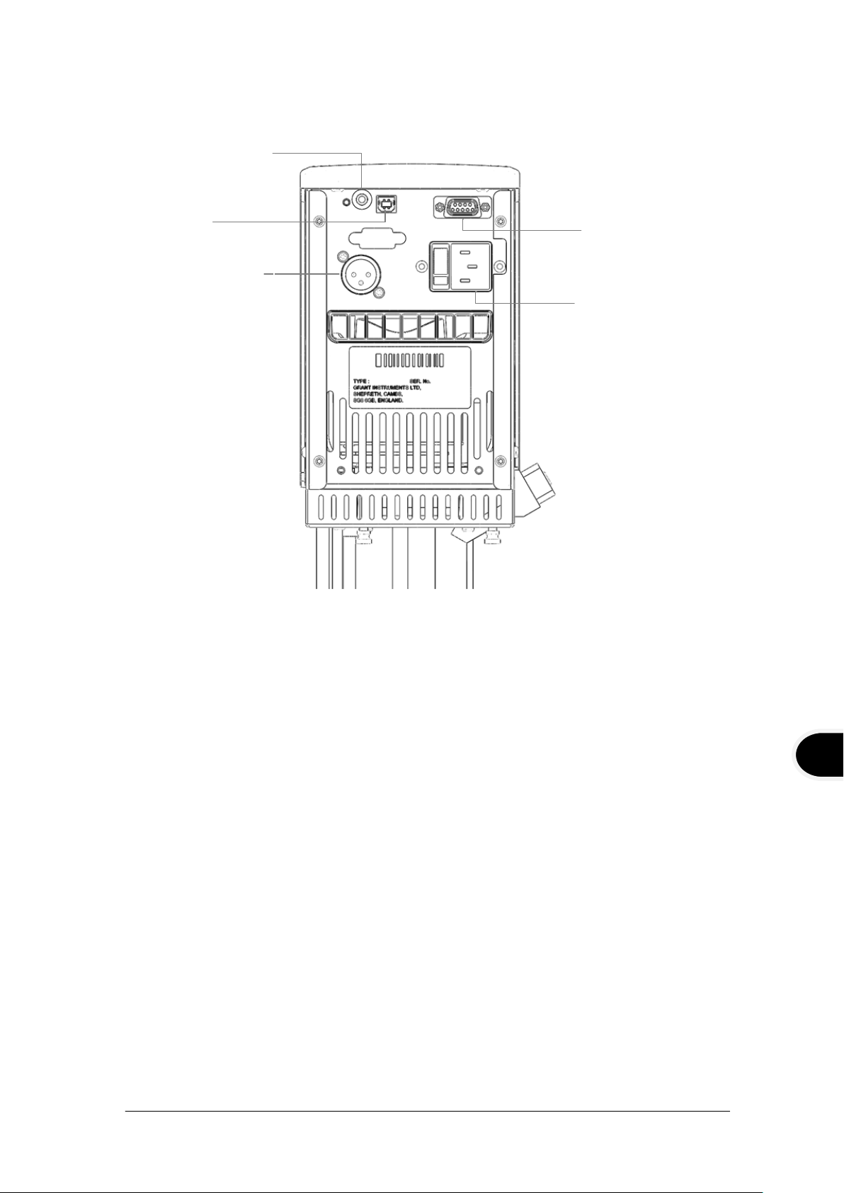
5.2.2 Rear panel connections
RS232 communcations
port
Mains power input
USB port
Switched relay port
External probe input
5.2.3 Communications ports
The TX150 and TXF200 provide a RS232 and a USB data port for communication with a
PC running Grant Labwise™ software. Labwise™ provides the ability to remotely
configure, control, monitor programs as well as log program temperature data.
Only use a RS232 cable supplied by Grant instruments.
The USB cable is a Type A to Type B style
5.2.4 Switched relay port
An internal relay provides switch over contacts that can be used to control external
equipment. See Section 5.1.5 for details of the relay contacts and connector type.
5.2.5 External probe input
For connecting an external PT1000 temperature probe available from Grant instruments
TX150 & TXF200 30424 V6
Operating Manual Page 14
www.grantinstruments.com
5.2.6 Setting the over-temperature thermostat
.
°c
.
°c
:
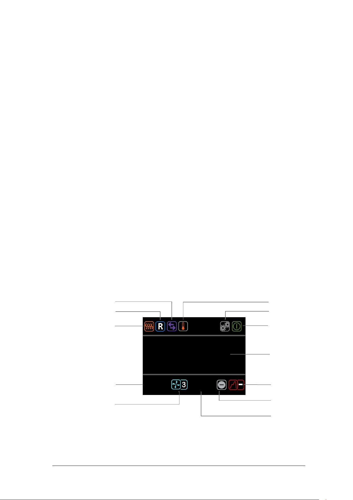
Settings
Standby
Actual temperature
External probe
Program
Preset
Countdown timer
Communication
Relay
Heater on
indicator (high
power)
Set temperature
Pump speed
(TXF200 only)
An over-temperature cut-out dial with a temperature scale is located at the top right of the
unit. The over-temperature probe independently monitors the bath temperature and
switches the heater off if it goes above the cut-out threshold.
Coarse setting of the over-temperature thermostat
Rotate the temperature cut-out dial in line with the marked scale to the desired setting.
This should be higher than the set temperature to avoid operating the cut-out before the
set temperature has been reached.
If the alarm is triggered the sounder can be silenced by pressing either the F or S button
once. To continue to use the TX150/TXF200, let the bath liquid cool by at least 5°C,
either naturally or by replacing the liquid, switch the unit off, wait 10 seconds and switch it
on again to clear the alarm. To avoid nuisance tripping the trip point needs to be set at
least 5°C above the desired control temperature.
Alternative setting of the over-temperature thermostat
Rotate the temperature cut-out dial to maximum (or at least a value above the level
required) and configure the set temperature to the cut-out level required. Leave the bath
to reach the set temperature and stabilise for at least 5 minutes. Turn the cut-out dial
slowly anticlockwise until an over-temperature fault is displayed on screen and the alarm
sounds continuously. This gives an over-temperature trip point at the set temperature.
The audible alarm can be cancelled by pressing either the F or S button once.
To continue to use the TX150/TXF200, let the bath liquid cool by at least 5°C, either
naturally or by replacing the liquid, switch the unit off, wait 10 seconds and switch it on
again to clear the alarm. To avoid nuisance tripping the trip point needs to be set at least
5°C above the desired control temperature.
5.2.7 Display. Explanation of home screen icons.
30424 V6 TX150 & TXF200
Page 15 Operating Manual
www.grantinstruments.com

EN
5.2.8 Description of user interface and controls
1. Rotate the dial until the set temperature icon is
highlighted, press the S button.
2. Rotate the dial to set the desired temperature.
If no key is pressed for 10 seconds or if F is
pressed, the set temperature icon is no longer
active and will remain at its original value.
3. Press S to store the requested value.
If the temperature selected is higher than the
current liquid temperature the heater will switch
on and the heater icon will be displayed.
The temperature setting range will be limited to
the operating range of the selected liquid.
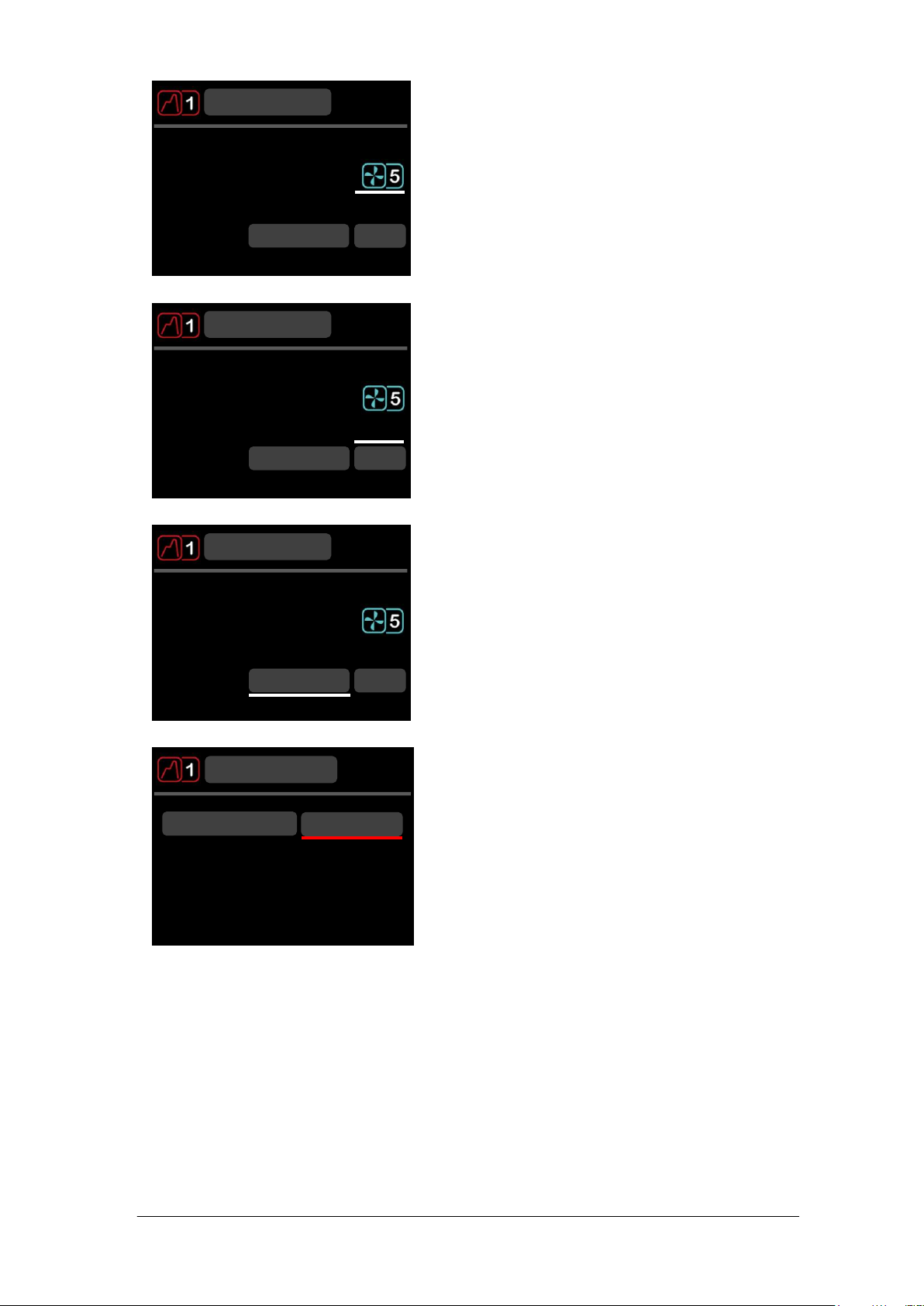
1. Rotate the dial until the pump speed icon is
highlighted, press the S button.
2. Rotate the dial to set the desired pump speed
over a range of 1 to 5 (1= lowest speed, 5 =
highest speed).
If no key is pressed for 10 seconds or if F is
pressed, the pump speed icon is no longer
active and will remain at its original value.
3. Press S to store the pump speed.
The pump will now operate at the stored pump
speed.
For set temperatures above 150°C, the pump
will automatically operate at a minimum of speed
3.
.
°c
.
°c
:
.
°c
.
°c
:
The TX150/TXF200 features a full colour graphic display, a main dial and two buttons F
and S. All functions (setting temperature, pump speed, countdown timer, presets,
programs settings and standby mode) can be configured from the home screen.
Navigation around the home screen is achieved by rotating the main dial which moves a
white cursor to highlight function icons. Pressing the S button whilst the icon is
highlighted will change the colour of the cursor to red, make the icon active and allow
changes to be made, or in the case of the settings icon, further menus to be displayed.
The primary function of the F button is to exit functions and menus. If F is pressed when
in the home screen whilst the cursor is white then the settings menu is displayed.
5.2.9 Setting the control temperature
Refer to section 4.6 to find the allowable temperatures for each liquid.
5.2.10 Setting a pump speed (TXF200 only)
TX150 & TXF200 30424 V6
Operating Manual Page 16
www.grantinstruments.com
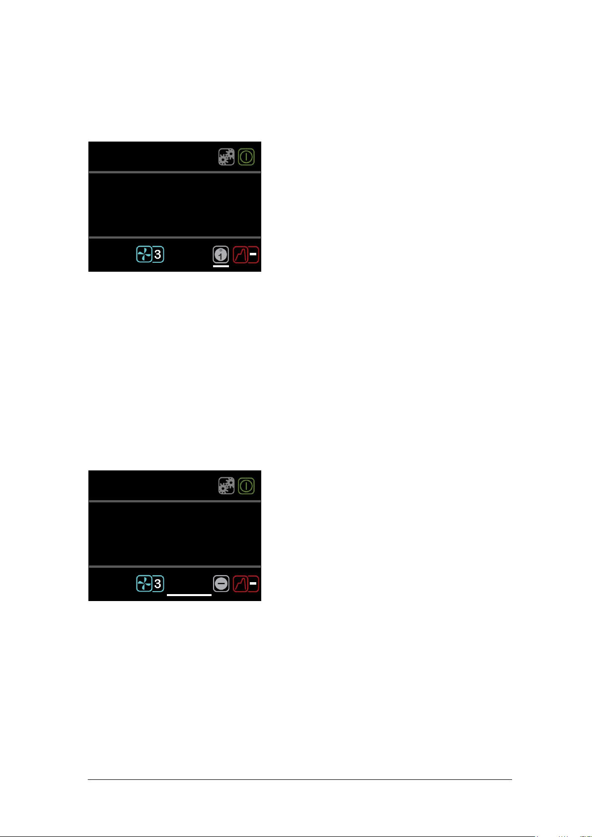
5.2.11 Running a bath preset
1. Rotate the dial until the preset icon is
highlighted, press the S button.
2. Rotate the dial to select the desired preset 1, 2
or 3, press S to run the preset.
The preset will automatically start as soon as S
is pressed.
If no key is pressed for 10 seconds or if F is
pressed the preset icon is no longer active and
will remain at its original value.
If the set temperature of the preset is not
allowed for the selected liquid (e.g. a preset of
150°C when using water) then the preset icon
will return to “–“ and the preset will not be used.
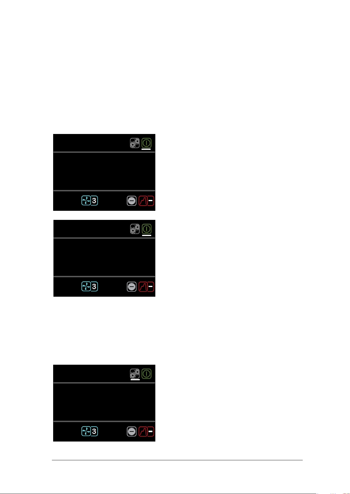
1. Rotate the dial until the countdown timer icon is
highlighted, press the S button.
The countdown timer will display the last
countdown time set.
If no key is pressed for 10 seconds or if F is
pressed the countdown timer setting is no longer
active and will remain at its original value.
2. Rotate the dial to set the desired countdown
time, press S to store.
The countdown timer will begin counting down
from the set time. At the end of the countdown
timer period a buzzer will sound. This can be
cancelled by pressing F or S.
.
°c
.
°c
:
.
°c
.
°c
:
Each TX150/TXF200 contains three presets which can be configured to different set
temperatures and in the case of the TXF200 the pump speed can additionally be
configured. This allows the bath to be conveniently run at frequently used temperatures
and pump speeds. See section 5.3.1 for information on preset configuration.
Refer to section 4.6 to find the allowable temperatures for each liquid.
5.2.12 Running a countdown timer
The countdown timer on the TX150/TXF200 can be set in the range of 1 minute to 99
hours. The countdown timer will sound a buzzer at the end of a countdown period. See
section 5.3.2 for information on configuring countdown timer expiry actions.
To cancel an active countdown timer:
1. Rotate the dial until the countdown timer icon is highlighted, press the S button.
2. Press the F button to cancel the countdown timer.
The countdown timer is stopped.
30424 V6 TX150 & TXF200
Page 17 Operating Manual
www.grantinstruments.com

EN
5.2.13 Running a program
1. Rotate the dial until the program icon is
highlighted, press the S button.
If no key is pressed for 10 seconds or if F is
pressed, the program icon is no longer active and
will remain at its original value.
2. Rotate the dial until the desired program is
displayed (TXF200 = 1 to 10). By default the
TX150/TXF200 will display program “–“ indicating
that no program is selected. Press S to select the
program.
The selected program will start. The display will
show the target temperature of the first segment
and the countdown timer will indicate the duration
of the program remaining. The TXF200 will display
the pump speed set for the first segment. Whilst a
program is running only the Standby icon can be
selected.
At the end of a program the buzzer will sound, this
can be cancelled by pressing F or S.
If the program is not valid, e.g. it has no segments
set up, or any segment of the program contains a
target temperature which is not valid for the
selected liquid, e.g. trying to ramp to 150°C using
water, then the program will not run and the
program icon will revert to “–“. Edit the program or
select a suitable liquid.
.
°c
.
°c
:
The TX150/TXF200 has the capability to run automatic temperature profiles called
programs. The TX150 has the capacity to store 1 program containing 30 individual
temperature/time segments. The TX150 can only be configured and edited using Grant
Labwise™ software The TXF200 has the capacity to store 10 programs, each containing
100 individual time/temperature segments. The TXF200 programs can be configured
directly on the unit or through Grant Labwise™ software. See section 5.3.2 for
information on program configuration via the unit (TXF200 only). When a program is
running icon access is limited to the standby and program functions
Refer to section 4.6 to find the allowable temperatures for each liquid.
To stop a program
1. Rotate the dial until the program icon is highlighted, press the S button.
If no key is pressed for 10 seconds or if F is pressed, the program icon is no longer
active and will remain at its original value and the program will continue to run.
2. Rotate the dial until the “–“ is displayed, press S to select
The program will stop. The display will remain at the set temperature reached when
the program was stopped, the countdown timer will stop at the remaining time and
the pump speed will display the last speed set.
TX150 & TXF200 30424 V6
Operating Manual Page 18
www.grantinstruments.com
5.2.14 Activating standby mode
1. Rotate the dial until the standby icon is
highlighted, press the S button.
The temperature and countdown timer
values are no longer displayed.
2. To resume operation, rotate the dial until the
standby icon is highlighted, press the S button.
The display returns to the home screen and the
TX150/TXF200 resumes operation at the last
temperature and pump speed set.
1. Rotate the dial until the settings icon is
highlighted, press the S button.
The settings menu is displayed, with presets
highlighted at the top of the list.
Shortcut to settings menu. Pressing F whilst in
the home screen when the cursor is white will
automatically display the settings menu
.
°c
.
°c
:
.
°c
.
°c
:
.
°c
.
°c
:
In standby mode the TX150/TXF200 is still powered, however key functions (heating,
pump, countdown timer and programs) are switched off. In standby mode access is
limited to the settings menu, enabling the functions such as alarms and programs to be
configured while the unit is not operating.
Note. When entering standby mode the pump will remain on for 5 minutes to allow
internal cooling to continue.
If a countdown timer has been set or a program is running before activating standby
mode they will be terminated.
5.2.15 Accessing the settings menu
The settings menu provides access to the following settings screens:
preset selection and definition, program selection and definition, liquid type, probe
(internal or external), alarms, buzzer level, relay state, language and display rounding.
Section 5.3 provides detailed information on viewing, editing and saving settings.
30424 V6 TX150 & TXF200
Page 19 Operating Manual
www.grantinstruments.com

EN
2. Rotate the dial to scroll up and down the list, until
the desired setting is highlighted, press the S
button to select. The desired settings menu is
displayed.
Pressing F returns to the home screen without
making changes.
.
°c
Presets
Settings
Programs
Liquid
Probe
TX150 & TXF200 30424 V6
Operating Manual Page 20
www.grantinstruments.com
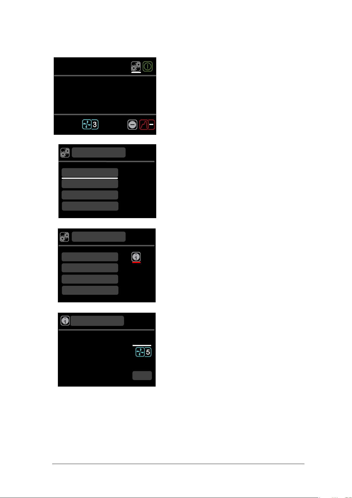
5.3 Viewing, editing and saving settings
1. Rotate the dial until the settings icon is highlighted,
press the S button.
Pressing F returns to the home screen without
making changes.
2. Rotate the dial to scroll up and down the list, until
presets is highlighted, press the S to select.
Pressing F returns to the settings screen without
making changes.
3. Rotate the dial to display preset icon 1, 2 or 3,
press S to select.
4. Temperature is highlighted, press the S button.
Rotate the dial to define the temperature. Press S
to set.
Pressing F restores the original preset temperature
with temperature highlighted.
.
°c
Temperature
Preset
Pump Speed
Save
°c
.
.
°c
Presets
Settings
Programs
Liquid
Probe
.
°c
Presets
Settings
Programs
Liquid
Probe
.
°c
.
°c
:
5.3.1 Configuring a preset
30424 V6 TX150 & TXF200
Page 21 Operating Manual
www.grantinstruments.com
EN
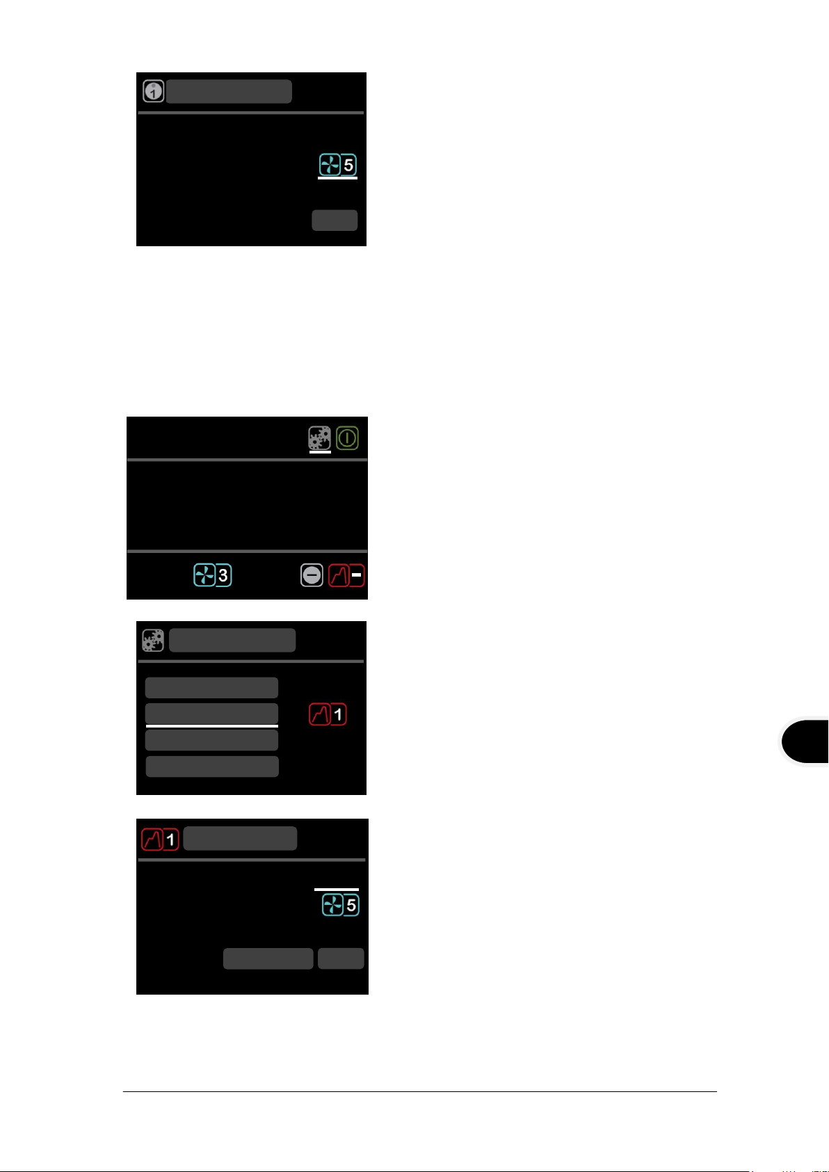
5. Rotate the dial to highlight pump speed, press S
to select. Rotate the dial to display pump speed (1
to 5), TXF200 only. Press S to set.
Pressing F restores the original preset pump
speed with pump speed highlighted.
To save the temperature and pump speed
configuration, rotate the dial to highlight save and
press S.
The display returns to the settings menu screen.
Repeat procedure to configure presets 2 and 3
6. Press F to return to the home screen.
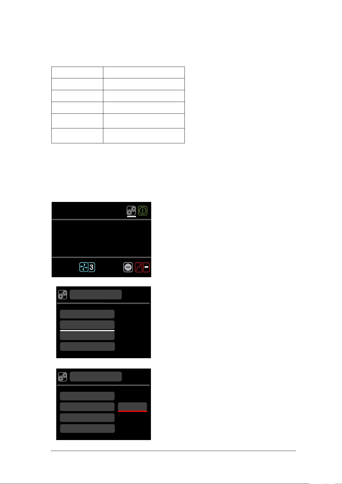
1. Rotate the dial until the settings icon is
highlighted, press the S button.
Pressing F returns to the home screen without
making changes.
2. Rotate the dial to scroll up and down the list, until
programs is highlighted, press S to select.
The program icon is displayed
3. Rotate the dial to select the program to be
created. Press S to select.
Segment 1 screen is displayed.
4. Target temperature is highlighted, press S to
select.
5. Rotate the dial to define the target temperature.
Press S to set.
.
°c
Target temperature
Pump speed
Duration (hh:mm)
Segment 01
Action
Save
.
:
Relay Off
.
°c
Presets
Settings
Programs
Liquid
Probe
.
°c
Temperature
Preset
Pump Speed
Save
.
.
°c
.
°c
:
5.3.2 Creating a program (TXF200 only)
TX150 & TXF200 30424 V6
Operating Manual Page 22
www.grantinstruments.com
6. Rotate the dial to highlight pump speed, press S
to select
7. Rotate the dial to the desired pump speed (1 to 5).
Press S to set.
8. Rotate the dial to highlight duration, press S to
select.
9. Rotate the dial to define the duration of the first
segment (hh:mm). Minimum segment duration is
1 minute, maximum 99 hrs 59 mins. Press S to
set.
10. Rotate the dial to highlight action, press S to
select.
11. Rotate the dial to toggle between relay on/off.
Press S to select.
12. Highlight save to store segment 1.
The program screen is displayed.
13. To insert a new segment, highlight segment 1,
press S. Rotate the dial to display insert after,
press S to select.
Segment 2 screen is displayed. Repeat steps 4 to
12 to create a new segment.
To dwell for a period at a particular temperature,
set the temperature to the same value as the
previous segment and then set the time to the
required dwell period.
14. On completion of programming, press F twice to
return to the home screen.
.
°c
001: Ends 00:10
Program
Insert after
.
°c
Target temperature
Pump speed
Duration (hh:mm)
Segment 01
Action
Save
.
:
Relay Off
.
°c
Target temperature
Pump speed
Duration (hh:mm)
Segment 01
Action
Save
.
:
Relay Off
.
°c
Target temperature
Pump speed
Duration (hh:mm)
Segment 01
Action
Save
.
:
Relay Off
30424 V6 TX150 & TXF200
Page 23 Operating Manual
www.grantinstruments.com

EN
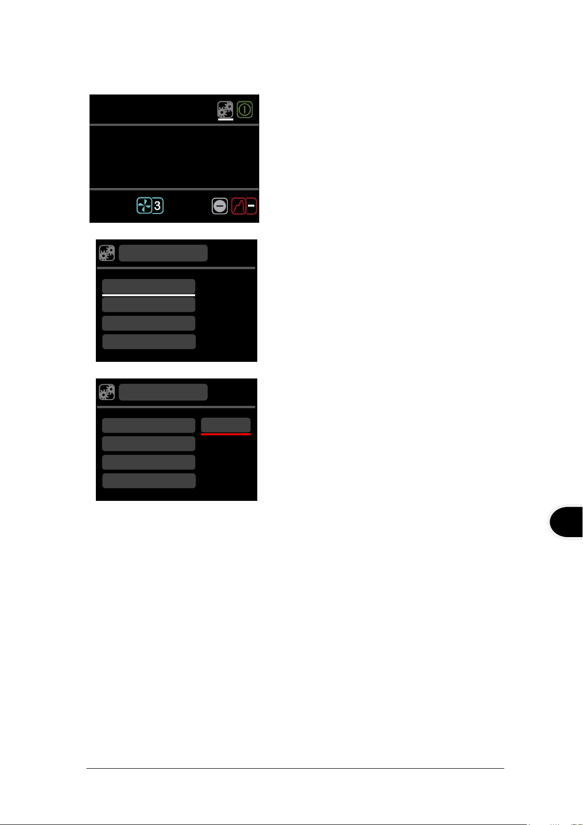
5.3.3 Editing a program (TXF200 only)
1. Rotate the dial until the settings icon is
highlighted, press the S button.
Pressing F returns to the home screen without
making changes.
2. Rotate the dial to scroll up and down the list, until
programs are highlighted, press S to select.
The program icon is displayed
3. Rotate the dial to select the program to be edited
(1 to 10). Press S to select.
The program screen is displayed.
4 Highlight the segment to be edited, press S.
5. Rotate the dial to display edit, press S to select.
The segment screen is displayed and can be
edited by following steps 4 to 12 in the previous
section ‘creating a program’.
6. Once editing is complete press F twice to return to
the home screen.
7. To delete a segment, highlight a segment, press
S.
8. Rotate the dial to display delete, press S to select.
The segment will be deleted.
9. Press F twice to return to the home screen.
.
°c
001: Ends 00:10
Program
Delete
002: Ends 00:20
.
°c
001: Ends 00:10
Program
Edit
002: Ends 00:20
.
°c
Presets
Settings
Programs
Liquid
Probe
.
°c
.
°c
:
TX150 & TXF200 30424 V6
Operating Manual Page 24
www.grantinstruments.com
5.3.4 Selecting a liquid type
Liquid
Set temperature range
Water
0°C to 100°C
Water-Glycol
*-30°C to 70°C
Low Temp Oil
-50°C to 50°C
High Temp Oil
†
70°C to 150°C (TX150)
¥
70°C to 200°C (TXF200)
Override
§-50°C to 150°C (TX150)
§-50°C to 200°C (TXF200)
1. Rotate the dial until the settings icon is
highlighted, press the S button.
2. Rotate the dial to scroll up and down the list until
liquid is highlighted, press S to select.
Liquid options are displayed.
3. Rotate the dial to scroll through the liquid options,
press S to save the selection.
The display returns to the settings screen.
4. Press F to return to the home screen.
.
°c
Programs
Settings
Liquid
Probe
Alarms
Water
.
°c
Programs
Settings
Liquid
Probe
Alarms
.
°c
.
°c
:
The liquid type determines the limits of the set temperature range.
Selection of the liquid types below changes the settable temperature range as follows:
* Water-Glycol (50% water, 50% antifreeze (inhibited ethylene glycol)
†
High Temp Oil (silicone fluid with the following characteristics: viscosity 20 centistokes,
flash point ≥230°C, fire point ≥280°C).
¥
High Temp Oil (silicone fluid with the following characteristics: viscosity 50 centistokes,
flash point ≥285°C, fire point ≥340°C).
§
When set to Override it is the user’s responsibility to select a suitable safe liquid.
See section 4.6 for full description of recommended bath liquids.
30424 V6 TX150 & TXF200
Page 25 Operating Manual
www.grantinstruments.com
EN
5.3.5 Selecting a temperature probe type
1. Rotate the dial until the settings icon is
highlighted, press the S button.
2. Rotate the dial to scroll up and down the list until
probe is highlighted, press S to select.
Probe options are displayed
3. Rotate the dial to scroll through the probe types
(external or internal), press S to save the
selection
The display returns to the settings screen.
The external probe icon will be displayed on the
home screen
4. Press F to return to the home screen.
.
°c
Probe
Settings
Alarms
Buzzer
Language
Internal
.
°c
Probe
Settings
Alarms
Buzzer
Language
.
°c
.
°c
:
The bath temperature can be controlled using an internal or external temperature probe.
TX150 & TXF200 30424 V6
Operating Manual Page 26
www.grantinstruments.com
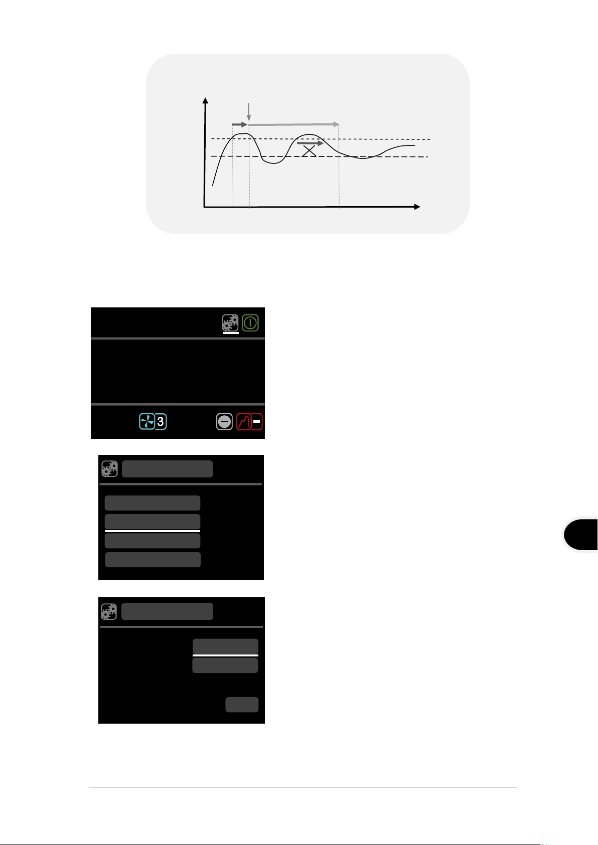
5.3.6 Configuring high and low temperature alarms
Liquid temp
Time
5
10
15
Temp
Alarm
Value -20˚C
Set temp -10˚C
Low temperature fixed alarm.
Liquid temp
Set
temperature
Deviation
5°C
Temp
Time
5
10
15
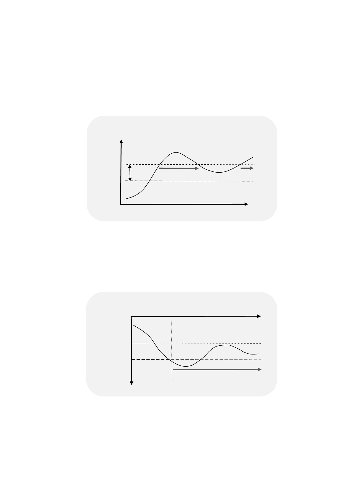
High temperature deviation alarm.
Alarm value
There are three functions in the alarm menu.
1. A high alarm function, which causes an alarm condition when the bath
temperature goes higher than the alarm value. The alarm value can be set as a
fixed temperature above the set temperature or a deviation offset value above the
set temperature. Below is an example of a high temperature deviation alarm,
where the deviation value has been set to 5˚C.
2. A low alarm function, when the bath temperature goes lower than the alarm
value. The alarm value can be set as a fixed temperature below the set
temperature or a deviation offset value below the set temperature. Below is an
example of a low temperature fixed alarm, where the fixed temperature value has
been set to -20˚C.
3. A hold-off time can be entered, which is a user adjustable time of between 0 and
30424 V6 TX150 & TXF200
Page 27 Operating Manual
21mins for which the alarms remain muted after either button has been pressed
to acknowledge an alarm condition. If the bath returns to the value such that the
alarm level is not exceeded the alarm will cancel. However, if the temperature
remains outside the alarm level the alarm condition will re-occur after this hold-off
time.
www.grantinstruments.com
EN
1. Rotate the dial until the settings icon is highlighted,
press the S button.
2. Rotate the dial to scroll up and down the list until
alarms are highlighted, press S to select.
3. High alarm mode is highlighted, press S to
select.
4. Rotate the dial to select fixed temp, deviation or
disabled. Press S to select.
The high alarm screen is displayed
.
°c
High Alarm mode
Alarm Settings
Low Alarm mode
Save
Fixed Temp
Disabled
Holdoff
:
.
°c
Probe
Settings
Alarms
Buzzer
Language
Liquid temp
Set point
temp
Temp
Time
5
10
15
Hold off time.
Alarm value
0
Hold off period 8 mins
Alarm acknowledged
2
.
°c
.
°c
:
Each alarm can be programmed to latch, activate an audible buzzer and a relay. Alarms
are cancelled by pressing the F or S button or if an alarm condition has been removed.
TX150 & TXF200 30424 V6
Operating Manual Page 28
www.grantinstruments.com

5. Temperature is highlighted, press S to select.
6. Rotate the dial to define the temperature value,
press S to set.
7. Rotate the dial to highlight latching, press S to
select.
8. Rotating the dial will display on/off, press S to
select.
When latching is on, a temperature alarm
continues unless acknowledged by the user even
if the temperature comes back in range
9. Rotate the dial to highlight relay, press S to select.
10. Rotating the dial will display on/off, press S to
select.
11. Rotate the dial to select buzzer, press S to select.
12. Rotating the dial will display on/off, press S to
select.
13. Rotate the dial to save, press S. The display
returns to the alarm settings screen. The
procedure can be repeated to configure a
deviation alarm and for the low alarm function.
14. Rotate the dial to highlight holdoff, press S to
select.
15. Rotate the dial to select a holdoff time (over a
range of 10 seconds to 21 minutes), press S to
select.
Rotate the dial to save, press S to save all
settings.
The display will return to the settings menu
16. Press F to return to the home screen
.
°c
High Alarm mode
Alarm Settings
Low Alarm mode
Save
Fixed Temp
Disabled
Holdoff
:
.
°c
Temperature
Latching
High Alarm
Off
°c
.
On
Relay
Buzzer
On
Save
30424 V6 TX150 & TXF200
Page 29 Operating Manual
www.grantinstruments.com
 Loading...