

Page 1

Squirrel Data Logger
2020/2040 SERIES
Getting Started
EN
FR
DE
IT
ES
Page 2

1. Hardware Checklist............................................................................2
2. General Information...........................................................................3
3. Communicating with your Logger ...................................................4
4. Quick Start Example..........................................................................8
5. Download Process Explained.........................................................12
6. Menu and Navigation.......................................................................13
7. Connections.....................................................................................15
8. Accessories......................................................................................17
9. Specifications...................................................................................19
10. Declaration of Conformity....................................inside rear cover
Contents
After reading this document,
please refer to the Help contents
within SquirrelView (press F1) for
further details on your logger and
how to use it with the software.
18108 Version 15 SQ2020/40
Page 1
www.grant.co.uk
Page 3
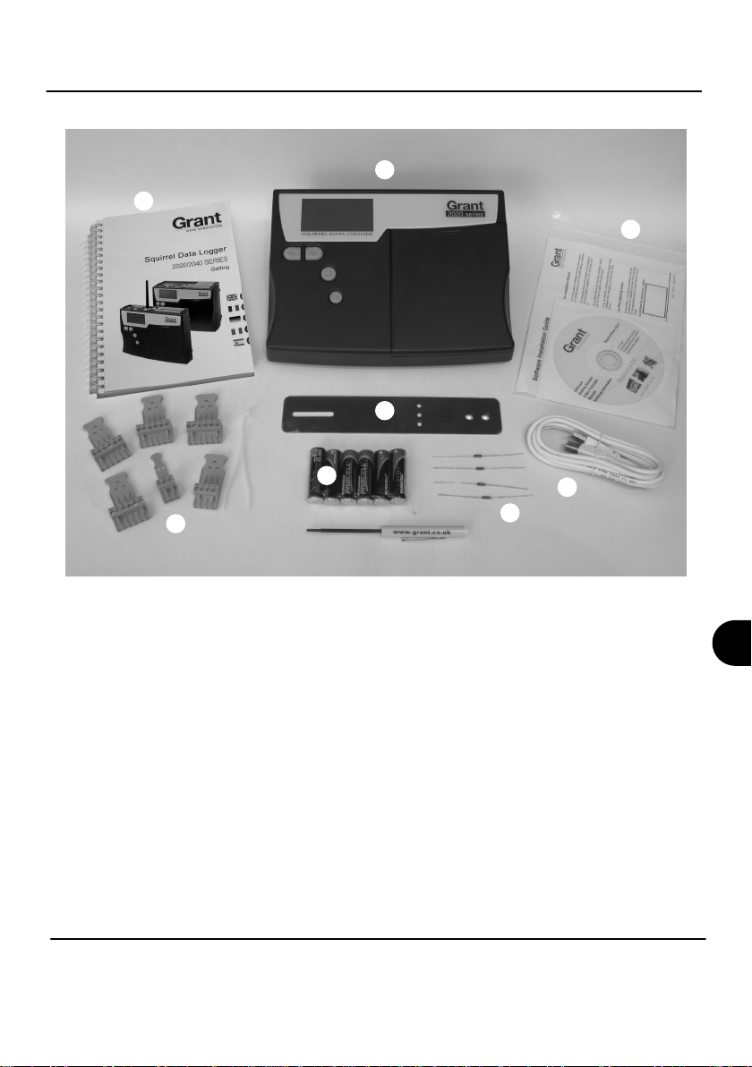
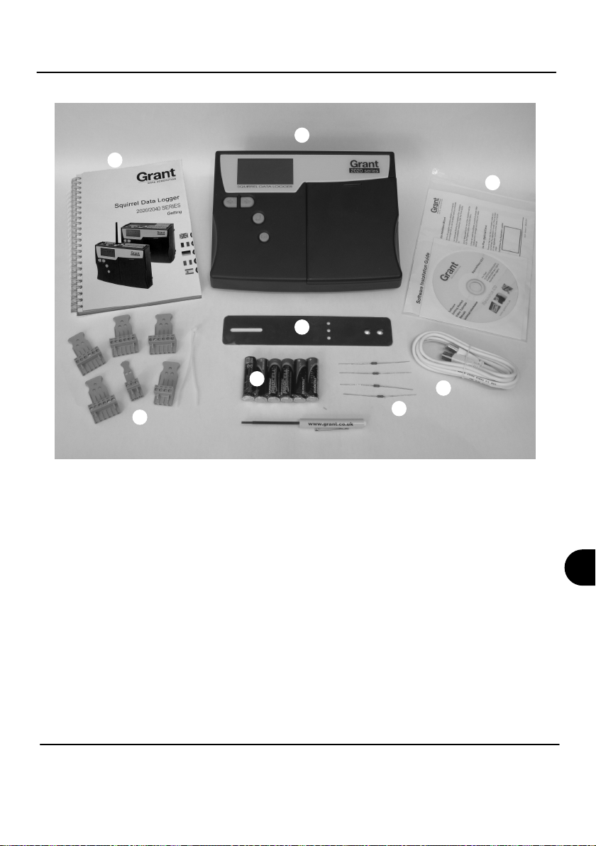
1. Hardware Checklist
A
C
B
E
F
H
G
D
A) SQ2020/2040 Logger
B) CD containing software (SQA100)
C) Getting Started manual (this booklet)
D) USB Cable (LC77)
E) Mounting bracket/stand for logger (WB6)
F) Batteries, 6 x AA
G) Current shunt resistors for 4 to 20mA inputs, 10R x 4 (CS202)
H) Connectors: 6 way x 4 (18097), 4 way (13975), 3 way
(14174), with cable ties
Note: 2040 Logger is supplied with 4 extra 6 way connectors
as above (18097).
Wi-fi version also contains an antenna.
SQ2020/40 18108 Version 15
www.grant.co.uk
Page 2
EN
Page 4
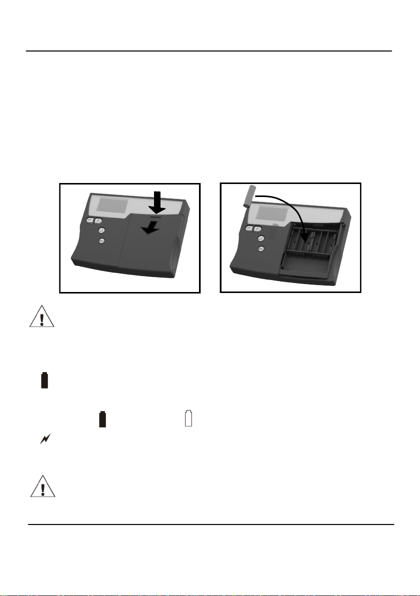
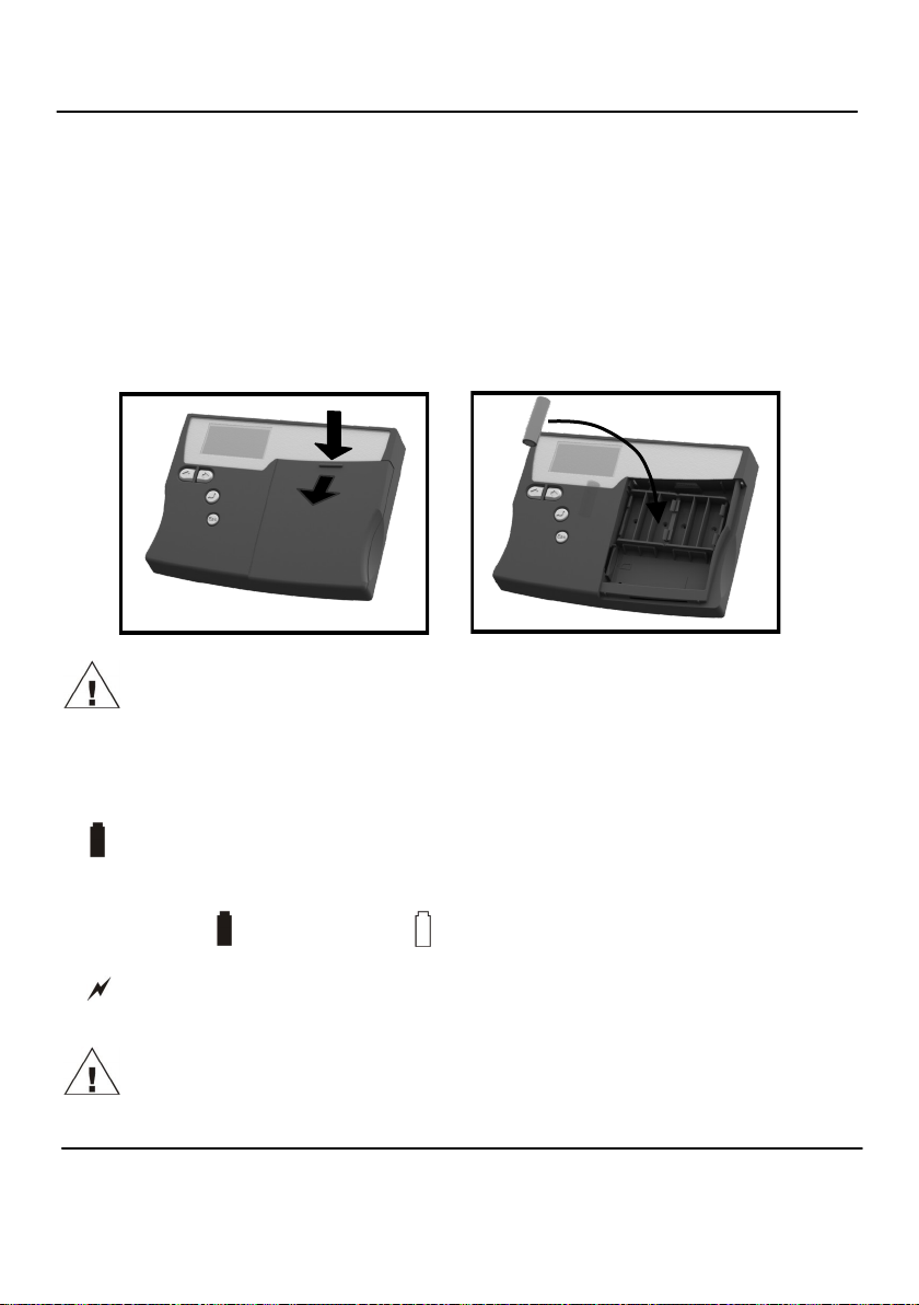
2.1 Installing the batteries
The 2020/2040 uses six AA size alkaline batteries located under the removable cover
shown below. To insert new or change the existing batteries:
1. Open the battery cover by pushing down and sliding as shown.
2. Insert six AA* batteries, ensuring the correct polarity.
3. Refit the battery cover
* It is recommended that all replacement batteries are of the same manufacturer, type
and condition.
2. General Information
Important: Remove the batteries when the logger is not used for long periods of
time or is being transported
2.2 Power indicator
Battery indicator
When logging please ensure that the batteries in the unit have sufficient capacity to
complete the logging task. This can be checked via the battery indicator located in the
top right of the display.
HIGH LOW
CAPACITY CAPACITY
External power indicator
The logger may be powered from an external source (10-18V DC)
Important: To ensure data protection in the case of an unexpected power loss,
please ensure that batteries are fitted whilst the unit is operational.
18108 Version 15 SQ2020/40
Page 3
www.grant.co.uk
Page 5

3. Communicating with your Logger
3.1 Installing the Software
For detailed installation instructions please see the supplied ‘Software Installation Guide’
supplement. For quick installation please see the steps below;
1. Ensure you have administration rights on the PC you wish to install software on
2. Ensure any current Grant applications are closed
3. Insert the CD into the CD\DVD drive of your computer and wait for it to autorun*
4. Follow the on screen installation wizard
* If after a few minutes autorun has not occurred select the Run option from the Windows
Start Menu. In the Command Line box, type d:\setup and press enter (where d:\ is your
CD\DVD drive, modify if required)
Important: Please ensure the software is installed before connecting the Squirrel data
logger.
3.2 Connecting your Squirrel Data Logger
You can connect to your logger by using one of the following methods;
1. Serial (RS232), including serial adaptors
2. USB
3. Ethernet (where fitted)
4. Wi-fi (where fitted)
Please see below for more information.
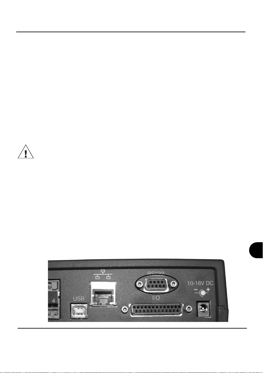
Serial (RS232)
For information on using serial adaptors please see the SquirrelView help file. If using a
straight serial (RS232) cable, connect one end to the serial port on the logger and the other
end to the PC’s serial port. Once connected you are ready to begin communications.
EN
SQ2020/40 18108 Version 15
www.grant.co.uk
Page 4
Page 6
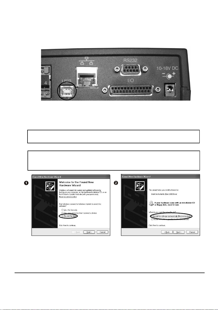
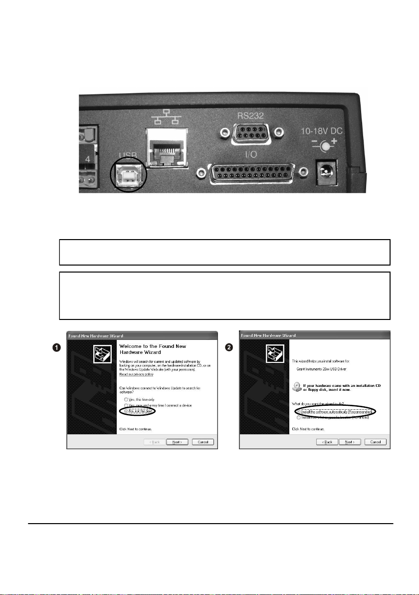
USB
Connect one end of the supplied USB lead to the logger and the other end to the PC.
On detection of the logger the PC will install the Grant Instruments SQ20XX USB device
drivers
Win 7/Vista - USB Device Drivers are automatically installed and no further action is required
Win XP - During the installation the USB drivers were pre-installed so the wizard will
automatically locate the driver. On the ‘Found New Hardware Wizard’ select ‘No, not this
time’ and for all the other screens select ‘Next’ to complete the installation.
Select Continue Anyway on the Hardware Installation warning which refers to Windows
Logo testing. Once the driver installation has completed you are ready to communicate to
your logger.
If you experience any problems refer to Troubleshooting->20xx USB Drivers in SquirrelView
Help.
18108 Version 15 SQ2020/40
Page 5
www.grant.co.uk
Page 7
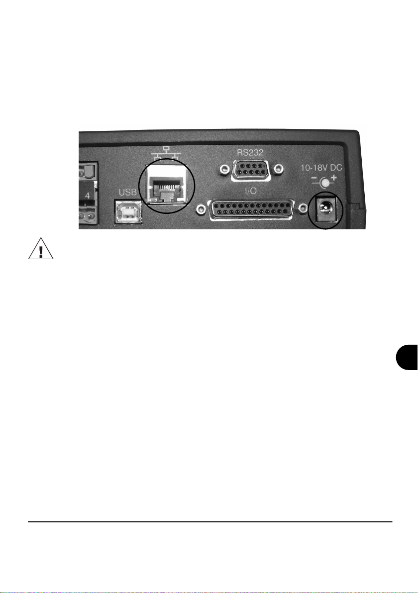
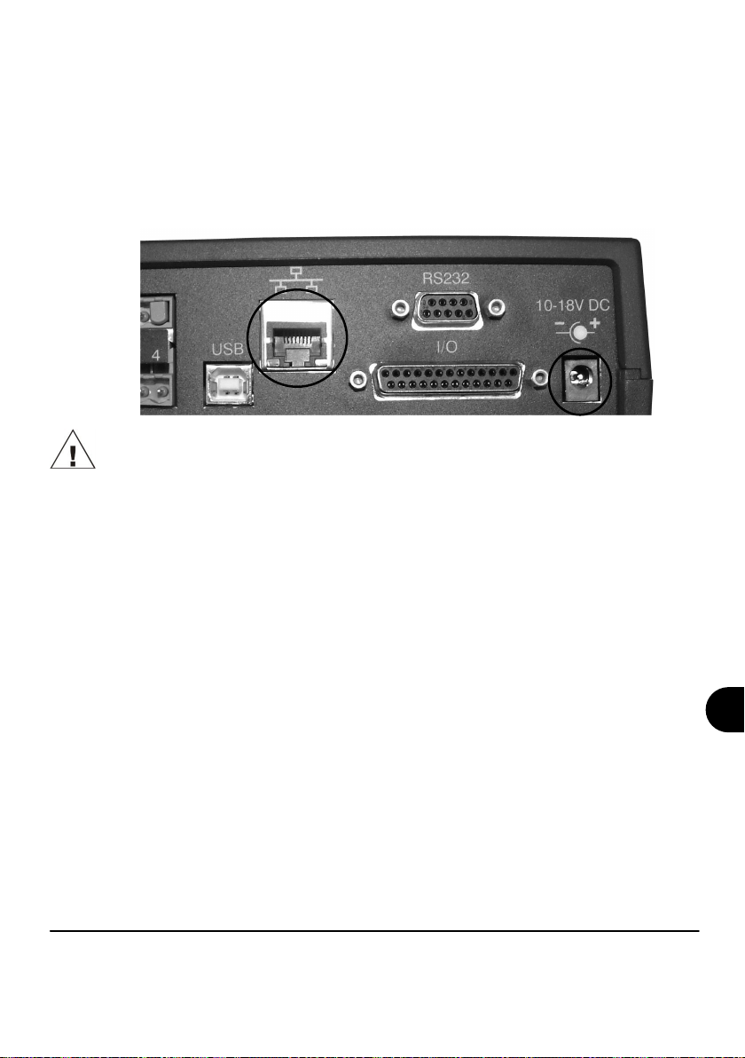
Ethernet
Before using the Ethernet connection please read the configuration manual which can be
found under ‘~\SquirrelView\Manuals\SQ20xx Inbuilt Ethernet Configuration.pdf’ where
‘~\SquirrelView’ is the installation directory of SquirrelView. Connect your Ethernet network
to the Ethernet port on the logger.
Ethernet is only available when the logger is connected to an external power supply.
SQ2020/40 18108 Version 15
Page 6
www.grant.co.uk
EN
Page 8
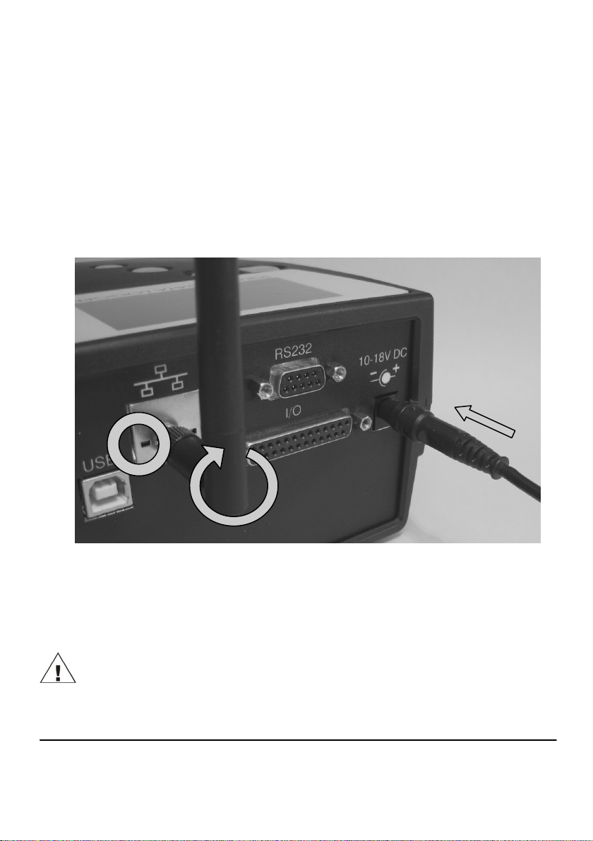
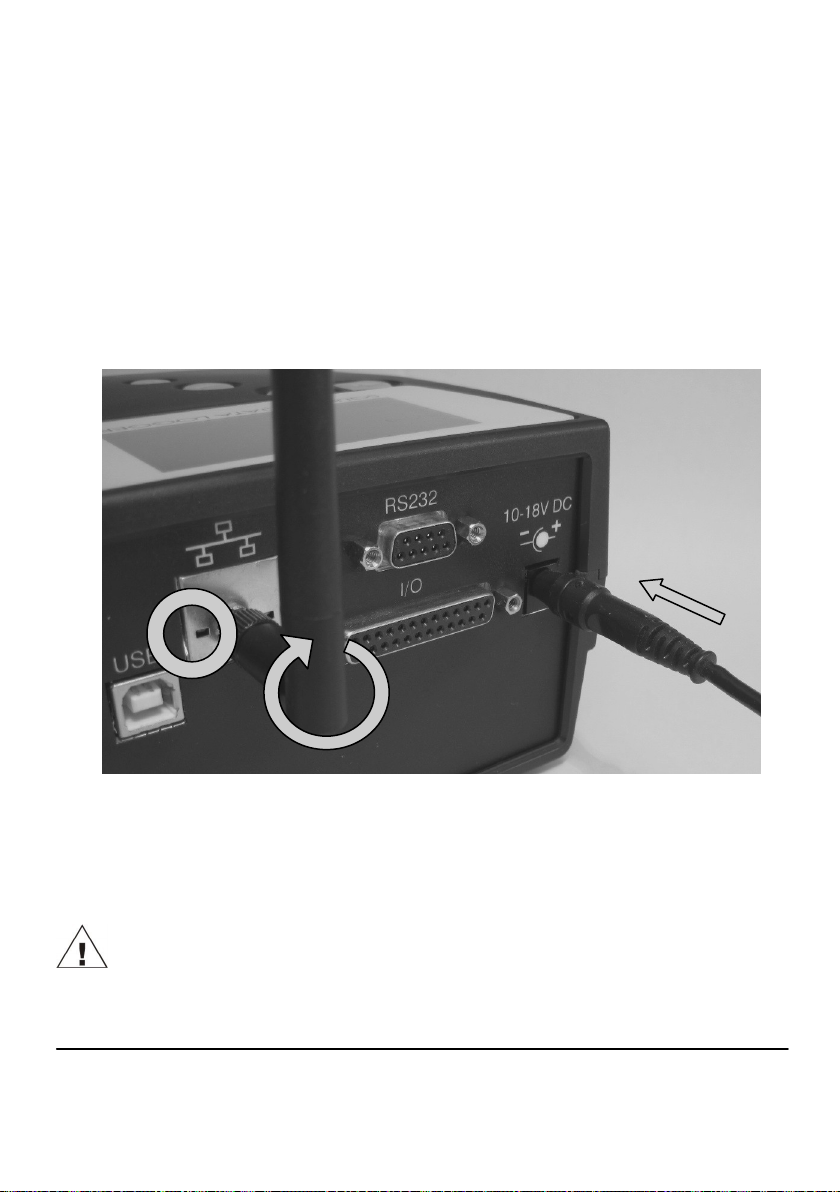
Wi-fi
Before using the Wi-fi connection it is necessary to assemble the antenna to the logger as
shown below.
1. Screw the antenna onto the threaded socket and orient it in the same direction as
the antenna on the receiver connected to the PC (usually vertical).
2. Attach an external power supply to the logger.
3. Turning on the power will cause the yellow and green lights on the module to start
flashing. A connection has been established when the yellow light stays on
permanently.
3
2
1
To complete the installation please refer to the configuration manual which can be found
under ‘~\SquirrelView\Manuals\SQ20xx Inbuilt Ethernet Configuration.pdf’ where
‘~\SquirrelView’ is the installation directory of SquirrelView.
Wi-fi is only available when the logger is connected to an external power supply.
18108 Version 15 SQ2020/40
Page 7
www.grant.co.uk
Page 9
4. Quick Start Example
After installing SquirrelView an example setfile will be installed within the SquirrelView
installation directory. The example file will log the internal temperature of the logger.
In order to familiarise yourself with the logger the novice user may find this example
Setup useful.
4.1 Start SquirrelView and Select Logger Type
Click on the shortcut icon on your desktop to launch SquirrelView or select it from your
start menu. When the SquirrelView Assistant is loaded, ensure the correct logger type
and communication method is selected.
Logger type can be viewed from the SquirrelView assistant, if you need to make any
changes select Logger Selection from the toolbar or run the Communication Wizard.
(Note: the default communication method is USB and you will need to change this via
the Communication Wizard if you are using any of the other communication methods).
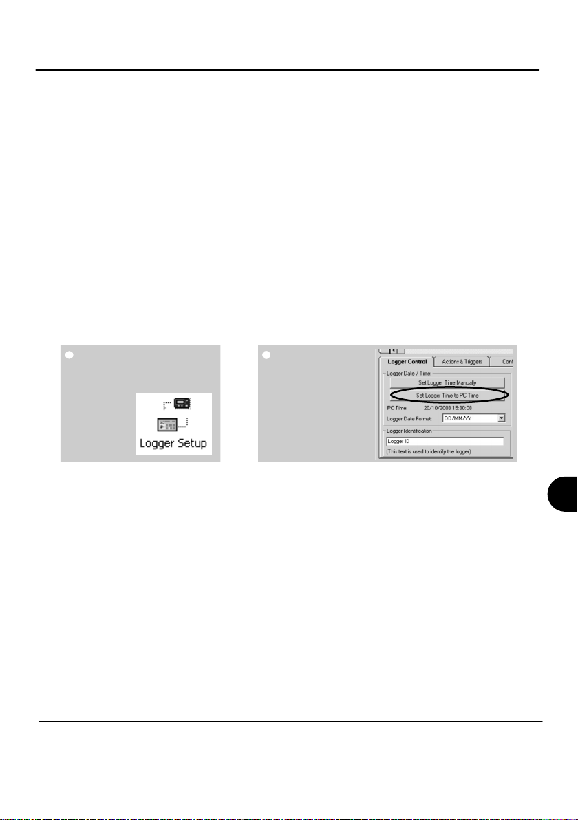
4.2 Synchronise Logger & PC
It is advisable to start by synchronising the Logger clock with the PC clock.
From
SquirrelView Assistant
click on Logger
Setup.
From the Logger
Setup screen select
the Logger Control
tab.
Click on ‘Set Logger
Time to PC Time’,
click OK on the
confirmation screen.
SQ2020/40 18108 Version 15
Page 8
www.grant.co.uk
EN
Page 10

4.3 Running Quick Start Demo
In the SquirrelView
Assistant click ‘Logger
Setup’ to enter the Logger Setup
screen. From here open the
demo setfile using File -> Open
and select the appropriate file for
your logger type.
The Logger
Setup screen
is now visible,
from here you
will be able to
set up your
logging
requirements.
Within the
Actual
Channels tab
scroll down the
Sensor Type
column to Ref.
Junction 1.
This is the
input you will
be reading in
this example.
The Job
Description
can be used to
describe your
setup.
18108 Version 15 SQ2020/40
Page 9
www.grant.co.uk
Page 11
Click
to send
setup to
logger
and start
logging. Let the unit
Click for
SquirrelView
Assistant.
Click
if you
wish to
meter
the input
in Real Time.
log for a few
minutes.
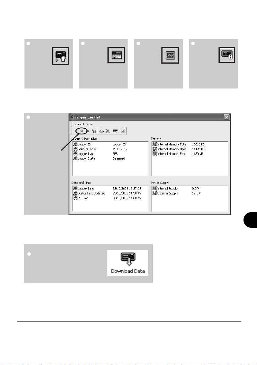
In the Logger
Control window
you can view
various status
information.
To stop logging,
click on the stop
button.
Click on
Logger
Control
to view
status of
logger
To Download the logger, click on
the ‘Download Data’ icon from the
SquirrelView Assistant.
SQ2020/40 18108 Version 15
www.grant.co.uk
Page 10
EN
Page 12
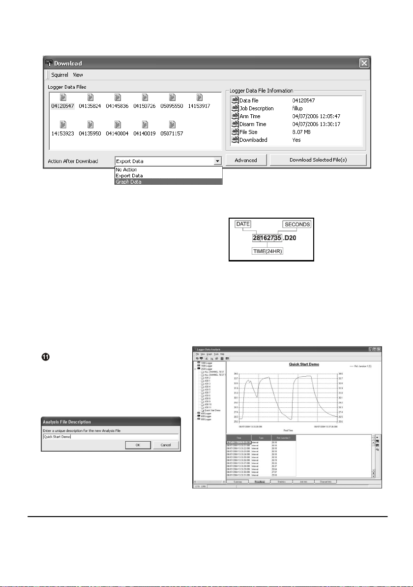
In this screen you can now download the Data File and invoke the Export Wizard or
download the Data File to Analysis* (See Download Process Explained).
The data File is given a unique name
(e.g. 28162735.D20). An explanation of
the file name is shown on the right; this
shows the date and start time
In this example you will download and view the Data in the Analysis* window. Start by
selecting the Data File and Graph Data action, then click Download Selected File(s).
You will be prompted to save the Data file, then the data will be converted for viewing.
Once the decoding has
taken place the Analysis File
Description window will be
presented, click OK to view
your Data.
*Available with SquirrelView Plus only.
18108 Version 15 SQ2020/40
Page 11
www.grant.co.uk
Page 13
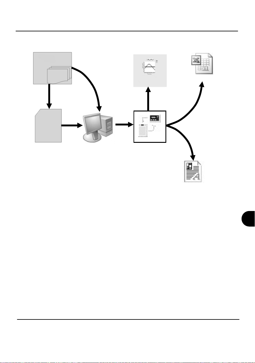
5. Download Process Explained
Logger
Data Files
(.d20)
(.d20)
Data File
external
MMC/SD
card
The Diagram above shows the download process. Data in the logger is written to the internal
memory and may be downloaded by SquirrelView.
Before the data can be viewed it must be converted by SquirrelView for Analysis or exported
to .csv or .xls format depending on the PC software being used.
The conversion process can be performed in one of three ways within SquirrelView:
in
Reader
Analysis File
(Plus Only)
Analysis
SquirrelView
Microsoft Excel
(.xls)
Export
(.csv)
Comma Separated Values
from SquirrelView assistant->Analysis->Export Data File
automatically when using the download Data button from SquirrelView*
or from the Logger Data Analysis screen by selecting File->Import Data menu*
Once the file has been downloaded it can be double clicked to open it with the program specified
under ‘Tools’, ‘Preferences’, ‘File Association Action’.
*Available with SquirrelView Plus only.
SQ2020/40 18108 Version 15
www.grant.co.uk
Page 12
EN
Page 14
6. Menu and Navigation
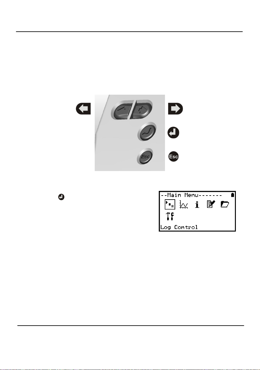
6.1 Control Panel
The illustration below shows the navigation controls in more detail.
LEFT/UP
NAVIGATION
To use the 2020/2040 control panel
press .
The display timeout is preset
to 10 seconds, this can be changed in
the Configuration tab within the Logger
Setup window of SquirrelView.
RIGHT/DOWN
NAVIGATION
ENTER/CONFIRM &
POWER ON
ESCAPE/BACK
(reverts to previous
Menu)
18108 Version 15 SQ2020/40
Page 13
www.grant.co.uk
Page 15

6.2 Control panel menu
Detailed below is a basic explanation of the top menu structure. For more information on
the whole menu structure please refer to the Help->Help Content->Loggers within
SquirrelView.
6.2.1 Log Control
In this menu you can Arm (activate), Pause
and Continue or Disarm (deactivate) the
logger.
6.2.2 Meter
Here you can view each channel in Real
Time (at 1-2Hz). Use the Enter key for a
graphical view of a channel.
6.2.3 Status
The Status menu gives you access to
information relating to the logger such as
available memory and power supply
voltage. You can also override the alarm
outputs from here.
6.2.4 Setup
This contains menus for setting up
Language, Time & Date, basic Channel
Setup, storing and recalling setups and
delayed starts.
See 6.3 for more details on basic setup
6.2.5 Data Files
This menu allows you to copy data files to
an external memory card (if fitted) and
delete the data files held within the
logger’s memory.
6.2.6 Tools
The Tools menu contains maintenance
type functions such as querying the
software version or IP address of the
logger, performing a self test and resetting
the logger.
EN
SQ2020/40 18108 Version 15
www.grant.co.uk
Page 14
Page 16
6.3 Creating a basic Setup
The 2020/2040 allows for the creation of a basic channel setup including logging interval, sensor type and sensor power (excitation) if required via the graphical interface, A
full setup including more advanced features can be performed using the SquirrelView
software included. Below is a brief explanation of how to create a basic channel using
the graphical interface
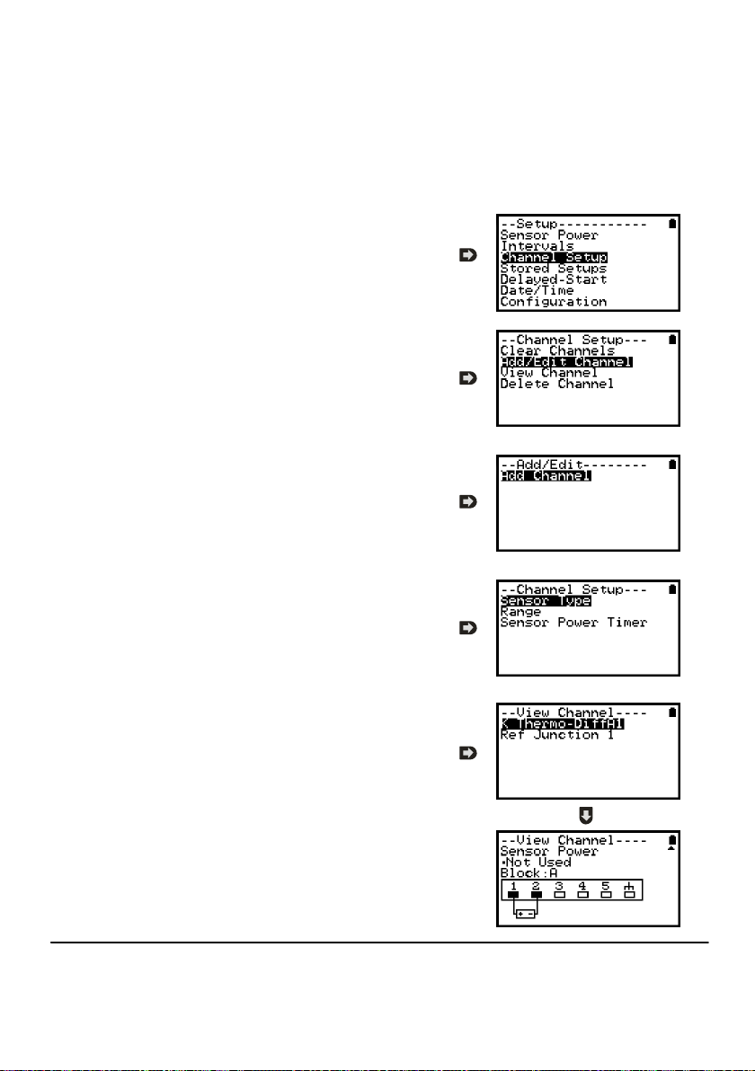
6.3.1 Channel Setup
From the ‘Main Menu’ choose the option
‘Setup’ then the option ‘Channel Setup’.
6.3.2 Adding or Editing a Channel
Once in ‘Channel Setup’ you can clear all
channels, add/edit a channel, view channel
details or delete a channel. Select ‘Add/Edit
Channel’.
6.3.3 Adding a New Channel
The ‘Add/Edit Channel’ menu shows channels
currently set as well as giving you the option to
add others. Select ‘Add Channel’
6.3.4 Channel Setup
Select the channel Sensor Type, Range and,
if required, which Sensor Power (excitation)
time is to be used .
6.3.5 Viewing Channels Setup
Once you have finished adding your required
channels and details the wiring configuration
can be viewed using the ‘View Channels’
option.
Note that Channel Descriptions are
automatically assigned based upon the
Sensor Type of the channel. This description
can be modified using SquirrelView if required.
18108 Version 15 SQ2020/40
Page 15
www.grant.co.uk
Page 17
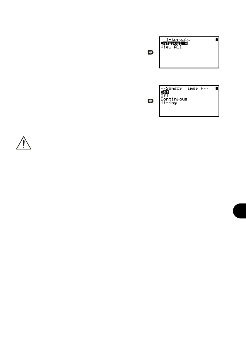
6.3.6 Interval Setup
A setup created from the control panel will
assign all channels to the same logging
interval. To change or view this interval choose
‘Intervals’ from the main ‘Setup’ menu.
6.3.6 Sensor Power Setup
The sensor power setup can be changed by
going to ‘Sensor Power’ from within the main
‘Setup’ menu.
Important Notes on Setup using the Control Panel
Full setup capabilities of the 2020/2040 are provided using the SquirrelView software
provide. When using the control panel a few important points should noted:-
Whilst all channels are assigned to the same interval, Interval A, all intervals can be
viewed in the case of a more complex setup from SquirrelView
To avoid problems with wiring configuration, sensor types are not editable once set but
their range and sensor power requirements can be. Delete a channel if you require to
change its Sensor Type
If the number of sensors is exceeded when adding new channels, the message "Invalid
Setup" will be displayed
Calculated channels setup from SquirrelView will not be shown on the view channels
option
The reference junction can not be deleted while a sensor type that requires it for
correct operation is set up, e.g. a thermocouple
You cannot change a setup whilst the logger is armed
The message "Sub-Second rate" will be displayed when attempting to view or edit a
Sample Intervals that have been set to less than 1 second. Use Squirrelview Logger
Setup to view or edit the sub-second Intervals
EN
SQ2020/40 18108 Version 15
www.grant.co.uk
Page 16
Page 18
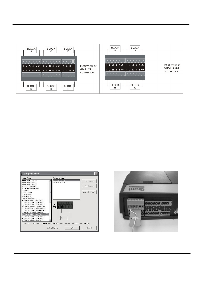
7. Connections
Analogue Inputs
NOTE: Blocks G to K as shown above are
only available on 2040 loggers.
As the wiring configuration is dependant upon the sensor type used, it is displayed in SquirrelView
during the setup. Follow the wiring diagram to attach the required sensor. If you would like to print
the diagrams in more detail or view at a later stage select ‘File > Print from Logger Setup’.
The example below shows the actual K type differential thermocouple sensor connected to the 2020
logger from the wiring diagram to the left.
18108 Version 15 SQ2020/40
Page 17
www.grant.co.uk
Page 19
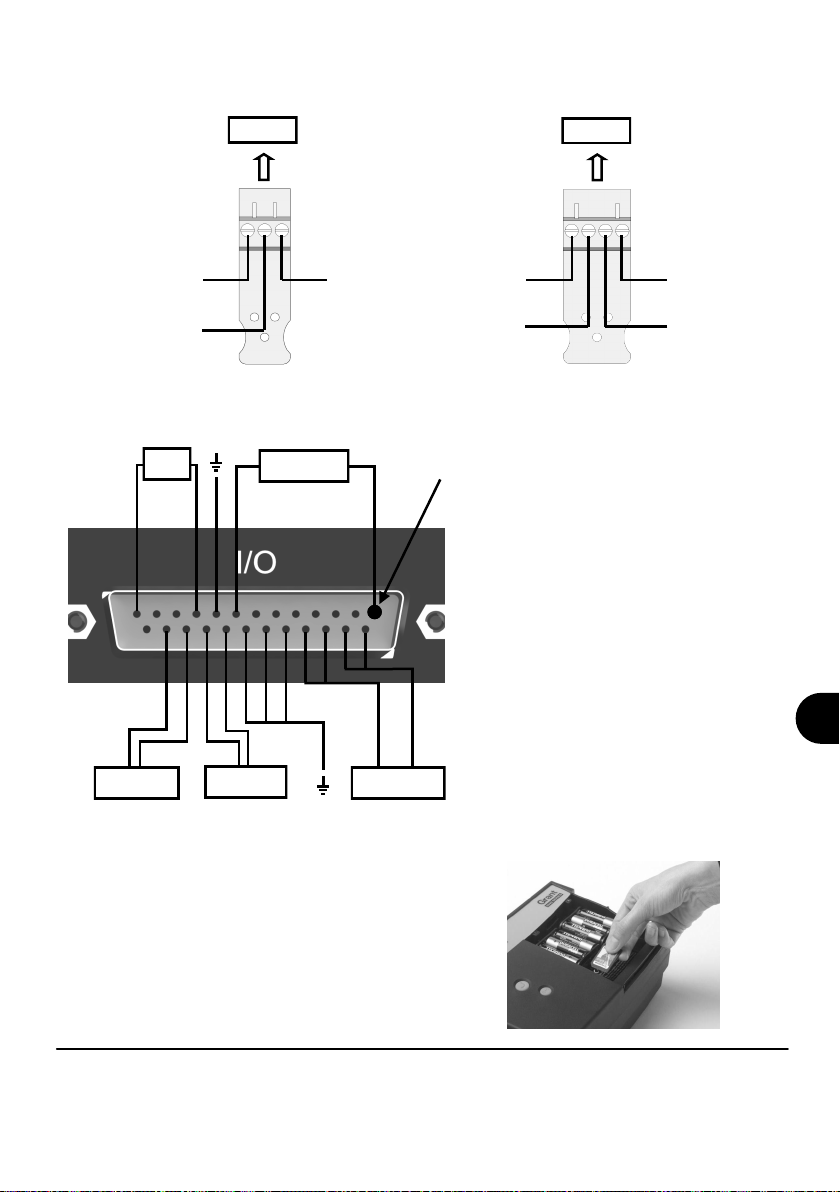
Sensor Power Wiring
Unregulated Logger
Supply Output
Regulated 5V Output
I/O Socket Wiring
ALARM
O/P
SLOW PULSE
I/P 1-2
Block E
EVENT/STATE
FAST PULSE
I/P 1-2
I/P 1-8
Negative
Auxiliary Output
Max. 500mA
PIN 1
+ve -ve
V1(+ve)
V1(-ve)
High Voltage Input
Block F
Pin Connection
1 Event/State Input 1
2 Event/State Input 2
3 Event/State Input 3
4 Event/State Input 4
5 Event/State Input 5
6 Event/State Input 6
7 Event/State Input 7
8 Event/State Input 8
9 Ground
10 Alarm Output A
11 Alarm Output B
12 Alarm Output C
13 Alarm Output D
14 Auxiliary Output +ve
15 Auxiliary Output +ve
16 Auxiliary Output -ve
17 Auxiliary Output -ve
18 Ground
19 Ground
20 Ground
21 Fast Pulse Input 1
22 Fast Pulse Input 2
23 Slow Pulse Input 1
24 Slow Pulse Input 2
25 No Connection
V2(-ve)
V2(+ve)
EN
External Memory Card Reader
The external SD card slot is located inside the battery
compartment.
SQ2020/40 18108 Version 15
www.grant.co.uk
Page 18
Page 20
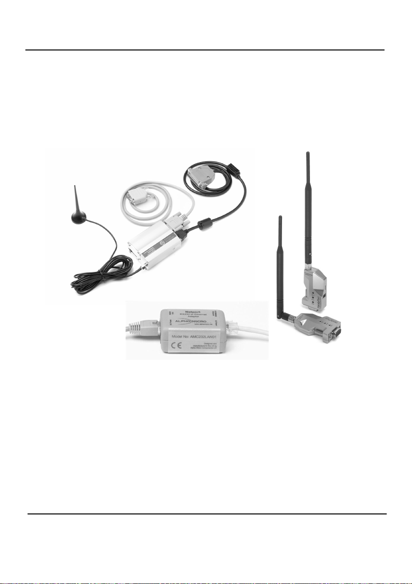
8. Accessories
Grant Instruments supply a wide range of accessories to compliment the range of Squirrel data
loggers. These include adapters as shown below which allow you to contact your Squirrel data
logger remotely. All are very easy to install and connect directly to the logger via RS232. If you
need any further details or wish to make a purchase please contact Grant or your local supplier for
more details.
GSM
Wireless
Ethernet
RS232 to Ethernet Converter consisting of adaptor box and modem setup Part No:
Cable. Ethernet configuration software is suitable for Windows 2000 and XP only. SQ20A801
GSM Modem kit comprising of modem, Squirrel connection cable, power lead
and antenna with 3m lead. A data-enabled SIM card will also be required
from your network service provider. SQ20A802
Wireless Adaptor comprising of an RS232 adaptor for connecting the logger to the
PC at baud rates up to 115K2 with a range of up to 200 metres using the 2.4GHz
frequency band. The kit is supplied with all connecting leads.
Note: power supplies (MPU 12V) to be ordered separately SQ20A803
18108 Version 15 SQ2020/40
Page 19
www.grant.co.uk
Page 21

Part No:
Removable external memory option
SD Memory Card. MMC64
Software packages for set-up, transfer and data analysis:
SquirrelView Plus
Provides full data analysis, on-line graphing, meter to Excel and export to Excel SQA200
SquirrelView Plus Multi-User License
Unlimited use of SquirrelView within a single organisation. SQA300
Calibration Certificates for Squirrel 2020/40 series (all ranges)
Note: Test and Calibration Certificates from Grant Instruments are traceable to
National Standards
SQ2020 CAL2020
SQ2040 CAL2040
Weatherproof box
Robust plastic weatherproof box PEL4
Wall bracket
Stainless steel wall and desk bracket WB6
Power supplies
100-240V AC 50/60Hz supplied with 3-single fit mains plugs for UK, Euro, and US MPU 12V
As MPU 12V but supplied with 1m flying lead MPU 12VFL
Rechargeable battery (12V, 6Ah) SQ20RB12-6
Rechargeable battery (12V, 15Ah) SQ20RB12-15
Digital I/O interface connector
25 way D connector type sub miniature solder connection with cover for digital
inputs, alarm and pulse inputs SB102
Current Shunts
Pack of 4 precision resistors for 4-20mA analogue channels CS202
Cables for connecting data loggers to computers/modems.
Squirrel to PC serial port LC71
Squirrel to PC USB port LC77
Squirrel to modem LC73
12V DC power lead
2.1mm DC connector and fused with 1.8m lead LC76
Terminal Blocks
Plug-in terminal blocks with cable restraint
3-way 14174
4-way 13975
6-way 18097
Temperature and Humidity probes
Grant offers a range of temperature and humidity probes suitable for use with its data loggers and
other compatible measurement systems. Bespoke or specialist probes are also available. Please
enquire if you have specialist probe needs.
EN
SQ2020/40 18108 Version 15
www.grant.co.uk
Page 20
Page 22

9. Specifications
ANALOGUE INPUTS
Basic accuracy (5-45°C): ..............................................± (0.05% readings + 0.025% range)
Common mode rejection: ...........................................................................................100dB
Input impedance: ...................................................................................................> 1MOHM
Linearity: ..................................................................................................................0.0015%
Series mode line rejection:...........................................................................50/60Hz 100dB
EM field and Conducted RF effect: ………………….………………….…...………….< 1% †
DIGITAL INPUTS
Zero input voltage....................................................................... 0 to 0.5V (or shorted input)
One input voltage..................................................................2.7 to 5V (or open circuit input)
Input protection......................................will turn on below about -0.5V and above about 6V
ANALOGUE-DIGITAL CONVERSION
Type: ....................................................................................................................Sigma-Delta
Resolution: .....................................................................................................................24bit
Sampling rate: ..................................................................Up to 20/100 readings per second
Note: 100Hz Mode not available on 1F8 models
ALARM OUTPUTS.......................................................................4 x open drain FET (18V 0.1A Max)
SENSOR POWER SUPPLY..............................Regulated 5 VDC (50mA) or supply voltage (100mA)
TIME AND DATE...........................................................................................In built clock in 3 formats
SCALING DATA.......................................................Displays readings in preferred engineering units
MEMORY
Internal: ...........................................................................128 Mb (Up to 14,400,000 readings)
External: ...........................................................Up to 1Gb removable MMC/SD memory card
RESOLUTION.................................................................................................Up to 6 significant digits
PROGRAMMING/LOGGER SET-UP................................SquirrelView or SquirrelView Plus software
COMMUNICATION.......................................................USB 1.1 and 2.0 / RS232 / Ethernet (not 1F8)
Internal option: ………………………………………………...……………………………...Wi-fi
External options: ......................................................................GSM, Ethernet and wireless
POWER SUPPLY
Internal: ..........................................................................................6*x AA Alkaline batteries
External: .........................................10-18VDC, reverse polarity and over-voltage protected
† This effect may be larger at 288kHz, re-orientate the input cables or add a suitable
axial ferrite bead close to the logger input if required.
* Maximum operating temperature for supplied alkaline batteries is 50°C
18108 Version 15 SQ2020/40
Page 21
www.grant.co.uk
Page 23

POWER CONSUMPTION @ 9V
Sleep mode: ..............................................................................................................<600µA
Logging: ..............................................................................................................40 - 120mA
DIMENSIONS AND WEIGHT
2020 Logger
Dimensions: ...................................................................................W235 x D175 x H55 mm
Weight: ............................................................................................................Approx 1.2kgs
Enclosure material: ...................................................................................................... ABS
2040 Logger
Dimensions: ...................................................................................W235 x D175 x H92 mm
Weight: .............................................................................................................Approx1.5kgs
Enclosure material:........................................................................................................ABS
MEMORY MODES (internal only)............................................................Stop when full or overwrite
DISPLAY AND KEYPAD
2 line x 20 character LCD
OPERATING ENVIRONMENT ...................................................................................-30°C to +65°C
Windows is a registered trademark of Microsoft
Corporation in the United States and other countries.
Due to our policy of continuous improvements, specifications may change
without prior notice.
Grant believe that all information declared is correct at the time of issue.
No liability is accepted for errors and omissions.
SQ2020/40 18108 Version 15
Page 22
www.grant.co.uk
EN
Page 24

Table des matières
1. Liste de contrôle du matériel .......................................................... 2
2. Généralités ....................................................................................... 3
3. Communiquer avec votre enregistreur ......................................... 4
4. Exemple de mise en route rapide .................................................. 8
5. Explication du processus de téléchargement ............................. 12
6. Menu et navigation ......................................................................... 13
7. Connexions .................................................................................... 15
8. Accessoires .................................................................................... 17
9. Spécifications ................................................................................. 19
10. Déclaration de conformité ....................... troisième de couverture
Après lecture de ce document,
consultez le contenu de l’Aide
dans SquirrelView (appuyez
sur F1) pour des informations plus
détaillées sur votre enregistreur et
son mode d’emploi avec le
logiciel.
18108 Version 15 SQ2020/40
Page 1
www.grant.co.uk
Page 25
1. Liste de contrôle du matériel
A
C
B
E
F
H
G
D
A) Enregistreur SQ2020/2040
B) CD contenant le logiciel (SQA100)
C) Manuel d’initiation (la présente brochure)
D) Câble USB (LC77)
E) Support de montage/socle pour l’enregistreur (WB6)
F) Piles, 6 x AA
G) Résistances de dérivation de courant pour entrées de 4 à
20 mA, 10R x 4 (CS202)
H) Connecteurs : 6 voies x 4 (18097), 4 voies (13975),
3 voies (14174), avec attaches de câble
Remarque : L’enregistreur 2040 est fourni avec 4 connecteurs
6 voies supplémentaires comme ci-dessus (18097).
La version Wi-fi comporte également une antenne.
SQ2020/40 18108 Version 15
www.grant.co.uk
Page 2
FR
Page 26
2.1 Installation des piles
Le 2020/2040 utilise six piles AA situées sous le couvercle amovible illustré cidessous. Pour insérer des piles neuves ou remplacer des piles usagées :
1. Ouvrez le couvercle des piles en le poussant vers le bas et en le faisant
coulisser comme illustré.
2. Insérez six piles AA*, en vérifiant que la polarité est correcte.
3. Replacez le couvercle des piles
* Il est conseillé d’utiliser des piles de rechange de même marque, type et état.
2. Généralités
Important : Retirez les batteries de l'enregistreur lorsqu'il n'est pas utilisé pendant
un certain temps ou lors de son transport.
2.2 Indicateur d’alimentation
Indicateur de batterie
Lors de la connexion, vérifiez que la capacité des piles de l’appareil est suffisante pour
terminer la tâche d’enregistrement. Vous pouvez le vérifier grâce à l’indicateur de
batterie situé en haut et à droite de l’affichage.
HAUTE FAIBLE
CAPACITÉ CAPACITÉ
Indicateur d’alimentation externe
L’enregistreur peut être alimenté par une source externe (10 à 18 V CC)
Important : Pour garantir la protection des données en cas de coupure
d’alimentation imprévue, vérifiez que les piles sont installées pendant que
l’appareil fonctionne.
18108 Version 15 SQ2020/40
Page 3
www.grant.co.uk
Page 27
3. Communiquer avec votre enregistreur
3.1 Installation du logiciel
Pour des instructions d’installation détaillées, consultez le supplément ‘Guide d’installation
du logiciel’ fourni. Procédez selon les étapes ci-dessous pour une installation rapide ;
1. Vérifiez que vous disposez des droits d’administration pour le PC sur lequel vous
souhaitez installer le logiciel
2. Vérifiez que toutes les applications Grant sont fermées
3. Insérez le CD dans le lecteur de CD\DVD de votre ordinateur et attendez qu’il
s’exécute automatiquement*
4. Suivez les instructions de l’assistant d’installation
* Si l’exécution automatique n’a pas démarré après quelques minutes, sélectionnez l’option
Run (Exécuter) dans le menu Démarrer de Windows. Dans la boite Command Line (Ligne
de commande), tapez d:\setup et appuyez sur entrée (où d:\ correspond à votre lecteur de
CD\DVD, à modifier au besoin)
Important : Vérifiez que le logiciel est installé avant de connecter l’enregistreur de
données Squirrel.
3.2 Raccordement de l’enregistreur de données Squirrel
Vous pouvez vous connecter à votre enregistreur à l’aide de l’une des méthodes suivantes ;
1. Série (RS232), y compris adaptateurs série
2. USB
3. Ethernet (si installé)
4. Wi-fi (si installé)
Consultez les informations complémentaires ci-dessous.
Série (RS232)
Consultez le fichier d’aide de SquirrelView pour des informations sur l’utilisation des adapta-
teurs série. Si vous utilisez un câble série direct (RS232), raccordez une extrémité au port
série de l’enregistreur et l’autre au port série du PC. Une fois la connexion établie, vous
pouvez commencer à communiquer.
FR
SQ2020/40 18108 Version 15
www.grant.co.uk
Page 4
Page 28
USB
Raccordez une extrémité du câble USB fourni à l’enregistreur et l’autre au PC.
Lors de la détection de l’enregistreur, le PC installe les pilotes de l'appareil USB.
Win 7/Vista - Les pilotes de l'appareil USB sont installés automatiquement ; aucune autre
action n'est requise.
Win XP - Les pilotes USB ont été préinstallés lors de l’installation, afin que l’assistant locali-
se automatiquement le pilote. Dans ‘Found New Hardware Wizard’ (Nouvel assistant matériel détecté) choisissez ‘No, not this time’ (Non, pas cette fois), puis ‘Next’ (Suivant) dans
tous les autres écrans pour terminer l’installation.
Sélectionnez Continue Anyway (Continuer quand même) lors de l’avertissement
d’installation matérielle se rapportant au test du logo Windows. Une fois l’installation du
pilote terminée, vous pouvez communiquer avec l’enregistreur.
Si vous rencontrez des difficultés, consultez la rubrique Dépannage->pilotes USB 20xx
dans l’aide de SquirrelView.
18108 Version 15 SQ2020/40
Page 5
www.grant.co.uk
Page 29
Ethernet
Avant d’utiliser la connexion Ethernet, lisez le manuel de configuration qui se trouve dans le
fichier ‘~\SquirrelView\Manuals\SQ20xx Inbuilt Ethernet Configuration.pdf’ où
‘~\SquirrelView’ est le répertoire d’installation de SquirrelView. Connectez votre réseau
Ethernet au port Ethernet de l’enregistreur.
Ethernet n’est disponible que lorsque l’enregistreur est raccordé à une alimentation
électrique externe.
SQ2020/40 18108 Version 15
Page 6
www.grant.co.uk
FR
Page 30
Wi-fi
Avant d’utiliser la connexion Wi-fi, il est indispensable d’assembler l’antenne sur
l’enregistreur comme illustré ci-dessous.
1. Vissez l’antenne dans l’orifice fileté et orientez-la dans la même direction que
l’antenne du récepteur connecté au PC (généralement à la verticale).
2. Raccordez une alimentation électrique externe à l’enregistreur.
3. La mise sous tension a pour effet de faire clignoter les voyants jaune et vert du
module. Une connexion est établie lorsque le voyant vert reste fixe en
permanence.
3
2
1
Pour terminer l’installation, lisez le manuel de configuration qui se trouve dans le fichier
‘~\SquirrelView\Manuals\SQ20xx Inbuilt Ethernet Configuration.pdf’ où ‘~\SquirrelView’ est
le répertoire d’installation de SquirrelView.
La Wi-fi n’est disponible que lorsque l’enregistreur est raccordé à une alimentation
électrique externe.
18108 Version 15 SQ2020/40
Page 7
www.grant.co.uk
Page 31

4. Exemple de mise en route rapide
Une fois SquirrelView installé, un exemple de fichier de configuration est installé dans
le répertoire d’installation de SquirrelView. Le fichier d’exemple enregistre la
température interne de l’enregistreur.
L’utilisateur novice peut trouver cet exemple de configuration utile pour se familiariser
avec l’enregistreur.
4.1 Démarrez SquirrelView et sélectionnez le type d’enregistreur
Cliquez sur l’icône de raccourci de votre bureau pour démarrer SquirrelView ou
sélectionnez-le dans votre menu de démarrage. Une fois l’assistant SquirrelView
chargé, vérifiez que le type d’enregistreur et la méthode de communication corrects
sont sélectionnés.
Le type d’enregistreur est indiqué dans l’assistant SquirrelView ; pour effectuer des
modifications, sélectionnez Logger Selection (choix de l’enregistreur) dans la barre
d’outils ou exécutez l’assistant de communication. (Remarque : la méthode de
communication par défaut est en USB. Elle doit être changée via l’assistant de
communication si vous utilisez d’autres méthodes de communication).
4.2 Synchronisez l’enregistreur et le PC
Il est conseillé de commencer par synchroniser l’horloge de l’enregistreur avec celle du
PC.
Dans l’écran Log-
Cliquez sur
Logger Setup
(Configuration
de l’enregis-
treur) dans
l’assistant
SquirrelView.
ger Setup
(Configuration de
l’enregistreur), sélectionnez l’onglet Log-
ger Control
(Commandes de l’en-
registreur). Cliquez
sur ‘Set Logger Time
to PC Time’ (Régler
l’heure de l’enregistreur sur celle du PC), cliquez
sur OK dans l’écran de confirmation.
FR
SQ2020/40 18108 Version 15
www.grant.co.uk
Page 8
Page 32

4.3 Exécution de la démonstration de mise en route rapide
Dans l’assistant SquirrelView
cliquez sur ‘Logger
Setup’ (Configuration de l’enregistreur) pour accéder à l’écran
du même nom. Ouvrez ensuite le
fichier de démonstration de configuration avec File -> Open
(Fichier->Ouvrir) et choisissez
le fichier correspondant au type
de votre enregistreur.
L’écran Logger
Setup
(Configuration de
l’enregistreur),
dans lequel vous
pouvez définir
vos besoins
d’enregistrement,
est affiché.
Dans l’onglet
Actual Channels
(Canaux ac-
tuels), faites
défiler la colonne
Sensor Type
(Type de cap-
teur) jusqu’à Ref.
Junction 1.
Il s’agit de l’en-
trée que vous
lirez dans cet
exemple.
La fonction
Job Description
(Description de la
tâche) peut servir
à décrire votre
configuration.
18108 Version 15 SQ2020/40
Page 9
www.grant.co.uk
Page 33

Cliquez
pour envoyer la
configuration à
l’enregistreur et
Cliquez
pour l’as-
sistant
SquirrelView.
Cliquez
pour me-
surer
l’entrée en
temps
réel.
commencer l’enre-
gistrement. Laissez
l’appareil enregistrer
pendant quelques
minutes.
Les différentes
informations d’é-
tat sont affichées
dans la fenêtre
Logger Control
(Commandes de
l’enregistreur).
Cliquez sur le
bouton d’arrêt
pour interrompre
l’enregistrement.
Cliquez
sur Logger
Control
(Comman-
des de
l’enregistreur) pour
afficher l’état de
l’enregistreur
Pour télécharger l’enregistreur,
cliquez sur l’icône ‘Download
Data’ (télécharger les données)
depuis l’assistant SquirrelView.
SQ2020/40 18108 Version 15
www.grant.co.uk
Page 10
FR
Page 34

Dans cet écran, vous pouvez maintenant télécharger le fichier de données et appeler
l’assistant d’exportation ou télécharger le fichier de données via la fonction Analysis*
(Analyse) (Voir l’explication du processus de téléchargement).
Un nom unique est attribué au fichier de données
(par exemple 28162735.D20). Une explication du
nom de fichier est fournie sur la droite ; elle indique la date et l’heure de début
Dans cet exemple, vous téléchargez et affichez les données de la fenêtre Analysis*
(Analyse). Commencez par sélectionner le fichier de données et l’action de données
graphiques, et cliquez sur Download Selected File(s) (Télécharger le(s) fichier(s)
sélectionné(s)). Vous êtes invité à enregistrer le fichier de données, avant que les
données soient converties pour l’affichage.
Une fois le décodage effectué, la
fenêtre Analysis File Description
(Description du fichier d’analyse)
s’ouvre ; cliquez sur OK pour afficher
vos données.
*Disponible uniquement avec SquirrelView Plus.
18108 Version 15 SQ2020/40
Page 11
www.grant.co.uk
Page 35

5. Explication du processus de téléchargement
Enregistreur
Fichiers de
données
(.d20)
Fichier
de don-
nées sur
carte
MMC/SD
externe
Lecteur
(.d20)
Analyse
Fichier d’analyse
(Plus seulement)
SquirrelView
Microsoft Excel
(.xls)
Exportation
(.csv)
Valeurs séparées par
des virgules
Le diagramme ci-dessus indique le processus de téléchargement. Les données de l’enregistreur
sont écrites dans la mémoire interne, et peuvent être téléchargées par SquirrelView.
Pour pouvoir afficher les données, elles doivent être converties par SquirrelView pour analyse ou
exportées au format .csv ou .xls, en fonction du logiciel PC utilisé.
Le processus de conversion peut être effectué selon trois méthodes dans SquirrelView :
depuis l’assistant SquirrelView ->Analysis->Export Data File
(SquirrelView ->Analyse->Exporter le fichier de données)
automatiquement en utilisant le bouton de téléchargement des données dans SquirrelView*
ou depuis l’écran Logger Data Analysis (Analyse des données de l’enregistreur) en choisis-
sant le menu File->Import Data (Fichier->Importer des données)*
Une fois le fichier téléchargé, il peut être ouvert avec le programme spécifié dans ‘Tools’ (Outils),
‘Preferences’ (Préférences), ‘File Association Action’ (Action d’association de fichier) en cliquant
deux fois dessus.
*Disponible uniquement avec SquirrelView Plus.
SQ2020/40 18108 Version 15
www.grant.co.uk
Page 12
FR
Page 36

6. Menu et navigation
6.1 Panneau de commande
L’illustration ci-dessous présente les commandes de navigation plus en détail.
NAVIGATION
GAUCHE/UP
Pour utiliser le panneau de commande du
2020/2040, appuyez sur la touche .
La temporisation de l’affichage est
préréglée sur 10 secondes, et peut être
modifiée dans l’onglet Configuration de la
fenêtre Logger Setup (Configuration de
l’enregistreur) de SquirrelView.
NAVIGATION
DROITE/BAS
ENTRÉE/
CONFIRMATION ET
MISE EN MARCHE
ECHAP/RETOUR
(revient au
menu précédent)
18108 Version 15 SQ2020/40
Page 13
www.grant.co.uk
Page 37

6.2 Menu du panneau de commande
L’explication de base de la structure du menu principal est détaillée ci-après. Pour des
informations plus détaillées sur la structure de menu complète, consultez Help->Help
Content->Loggers (Aide -> Contenu de l’aide -> Enregistreurs dans SquirrelView.
6.2.1 Log Control (Commande d’enregistrement)
Ce menu permet d’armer (activer) ou
désarmer (désactiver) l’enregistreur.
6.2.2 Meter (Compteur)
Permet d’afficher chaque canal en temps
réel (à 1 à 2 Hz). Utilisez la touche entrée
pour obtenir l’affichage graphique d’un
canal
6.2.3 Status (État)
Le menu Status (État) permet d’accéder
aux informations relatives à l’enregistreur
menu, notamment la mémoire et la tension
d’alimentation. Vous pouvez également y
annuler les sorties d’alarme.
6.2.4 Setup (Configuration)
.Contient les menus de réglage de la langue,
de l’heure, de la date, la configuration de canal
de base, les réglages de stockage et de rappel
des configurations et le démarrage différé.
Des informations plus détaillées sur la
configuration de base sont présentées dans
la section 6.3
6.2.5 Data Files (Fichiers de données)
Ce menu permet de copier les fichiers de
données sur une carte mémoire externe (s’il
y a lieu) et de supprimer les fichiers de
données contenus dans la mémoire de
l’enregistreur.
6.2.6 Tools (Outils)
Le menu Tools (Outils) contient des
fonctions de maintenance
telles que la requête de la version du
logiciel ou l’adresse IP de l’enregistreur,
l’exécution d’un autotest et la réinitialisation
de l’enregistreur.
FR
SQ2020/40 18108 Version 15
www.grant.co.uk
Page 14
Page 38

6.3 Création d’une configuration de base
Le 2020/2040 permet la création d’une configuration de canal de base comprenant
l’intervalle d’enregistrement, le type de capteur et l’alimentation du capteur (excitation)
si nécessaire via l’interface graphique ; une configuration complète comprenant des
fonctions plus avancées peut être effectuée à l’aide du logiciel SquirrelView fourni. Une
brève explication de la méthode de création d’un canal de base en utilisant l’interface
graphique est présentée ci-dessous
6.3.1 Configuration de canal
Depuis le ‘Main Menu’ (Menu principal), choi-
sissez l’option ‘Setup’ (Configuration) puis
l’option ‘Channel Setup’ (Configuration de
canal).
6.3.2 Ajout ou modification d’un canal
Dans ‘Channel Setup’ (Configuration de canal),
vous pouvez effacer tous les canaux, ajouter/
modifier un canal, afficher les détails d’un canal ou supprimer un canal. Sélectionnez ‘Add/
Edit Channel’ (Ajouter/modifier un canal).
6.3.3 Ajout d’un nouveau canal
Le menu ‘Add/Edit Channel’ ‘Ajouter/modifier
un canal) affiche les canaux actuellement
configurés et vous permet d’en ajouter d’autres. Sélectionnez ‘Add Channel’ (Ajouter un
canal)
6.3.4 Configuration de canal
Choisissez le type de capteur et la plage du
canal et, au besoin, la durée d’alimentation du
capteur (excitation) devant être utilisée.
6.3.5 Affichage de la configuration de canaux
Une fois les canaux nécessaires et les détails
ajoutés, la configuration de câblage peut être
affichée avec l’option ‘View Channels’ (Afficher
les canaux).
Notez que les descriptions de canal sont auto-
matiquement attribuées, en fonction du type de
capteur du canal. Cette description est modifia-
ble avec SquirrelView s’il y a lieu.
18108 Version 15 SQ2020/40
Page 15
www.grant.co.uk
Page 39

6.3.6 Réglage de l’intervalle
Une configuration créée depuis le panneau de
commandes attribue le même intervalle d’enre-
gistrement à tous les canaux. Pour modifier ou
afficher cet intervalle, choisissez
‘Intervals’ (Intervalles) dans le menu
‘Setup’ (Configuration).
6.3.6 Configuration de l’alimentation du capteur
La configuration de l’alimentation du capteur
peut être modifiée en accédant à l’option
‘Sensor Power’ (Alimentation du capteur) dans
le menu ‘Setup’ (Configuration).
Remarques importantes sur la configuration à l’aide du panneau de commandes
Les capacités de configuration complètes du modèle SQ2020/2040 sont fournies par le
logiciel SquirrelView. Lorsque vous utilisez le panneau de commandes, quelques aspects importants doivent être notés :-
Bien que le même intervalle (intervalle A) soit affecté à tous les canaux, tous les inter-
valles peuvent être affichés dans SquirrelView dans le cas d’une configuration plus
complexe
Pour éviter les problèmes de câblage de configuration, les types de capteur ne sont
pas modifiables une fois déterminés, contrairement à leur plage et alimentation nécessaire. Supprimez un canal si vous devez changer son type de capteur
Si le nombre de capteurs est dépassé lorsque vous ajoutez de nouveaux canaux, le
message « Mauvaise config. » s'affiche
Les configurations de canaux calculés dans SquirrelView ne sont pas affichées par
l’option d’affichage des canaux
Il est impossible de supprimer une jonction de référence lorsqu’un type de capteur qui
l’utilise pour fonctionner correctement est configuré, par exemple un thermocouple A.
Vous ne pouvez pas modifier une configuration lorsque l’enregistreur est armé
Le message « Vitesse < seconde » apparaît lorsque vous tentez d'afficher ou de modi-
fier des intervalles d'échantillonnage qui ont été définis sur moins d'1 seconde. Utilisez
Squirrelview Logger Setup pour afficher ou modifier les intervalles
FR
SQ2020/40 18108 Version 15
www.grant.co.uk
Page 16
Page 40

Entrées analogiques
7. Connexions
BLOC
A
BLOC
C
BLOC
E
Vue arrière
des
connec-
BLOC
G
BLOC
J
Vue arrière des
connecteurs
ANALOGIQUES
teurs
ANALOGI-
BLOC
B
BLOC
D
BLOC
F
QUES
BLOC
H
BLOC
K
REMARQUE : Les blocs G à K illustrés ci-
dessus ne sont disponibles
que sur les enregistreurs 2040.
La configuration de câblage dépendant du type de capteur utilisé, elle est affichée dans SquirrelView
lors de la configuration. Consultez le schéma de câblage pour raccorder le capteur correct. Pour
imprimer les schémas sous une forme plus détaillée ou les consulter ultérieurement, sélectionnez
‘File > Print from Logger Setup’ (Fichier > Imprimer depuis la configuration de l’enregistreur).
L’exemple ci-dessous montre le capteur de thermocouple différentiel de type K réel raccordé à
l’enregistreur 2020 dans le schéma de câblage de gauche.
18108 Version 15 SQ2020/40
Page 17
www.grant.co.uk
Page 41

Câblage d’alimentation du capteur
Enregistreur
non régulé
Sortie
d’alimentation
Sortie 5 V régulée
Câblage de la prise E/S
ALARME
O/P
IMPULSION
LENTE I/P 1-2
IMPULSION
RAPIDE I/P 1-2
Bloc E
ÉVÉNEMENT/
ÉTAT I/P 1-8
Négatif
Sortie auxiliaire put
Max. 500 mA
V1(+ve)
V1(-ve)
BROCHE 1
+ve -ve
Entrée haute tension
Bloc F
Broche Connexion
1. Événement/État Entrée 1
2. Événement/État Entrée 2
3. Événement/État Entrée 3
4. Événement/État Entrée 4
5. Événement/État Entrée 5
6. Événement/État Entrée 6
7. Événement État Entrée 7
8. Événement État Entrée 8
9. Masse
10. Alarme Sortie A
11. Alarme Sortie B
12. Alarme Sortie C
13. Alarme Sortie D
14. Sortie auxiliaire +ve
15. Sortie auxiliaire +ve
16. Sortie auxiliaire -ve
17. Sortie auxiliaire -ve
18. Masse
19. Masse
20. Masse
21. Impulsion rapide Entrée 1
22. Impulsion rapide Entrée 2
23. Impulsion lente Entrée 1
24. Impulsion lente Entrée 2
25. Sans connexion
V2(-ve)
V2(+ve)
FR
Lecteur de carte mémoire externe
Le connecteur de carte SD externe est situé dans le
compartiment des piles.
SQ2020/40 18108 Version 15
www.grant.co.uk
Page 18
Page 42

8. Accessoires
Grant Instruments propose un large éventail d’accessoires qui complètent la gamme
d’enregistreurs de données Squirrel. Ces accessoires comprennent des adaptateurs comme
illustrés ci-dessous qui permettent de contacter votre enregistreur de données Squirrel à distance.
Ils sont tous très faciles à installer et se raccordent directement à l’enregistreur via le connecteur
RS232. Pour des informations plus détaillées ou pour passer une commande, contactez Grant ou
votre fournisseur local.
GSM
Sans fil
Ethernet
Convertisseur RS232 vers Ethernet composé d’un boîtier adaptateur et d’un câble
d’installation du modem. Le logiciel de configuration Ethernet convient uniquement
aux systèmes d’exploitation Windows 2000 et XP. SQ20A801
Kit modem GSM comprenant un modem, un câble de connexion Squirrel,
un câble d’alimentation et une antenne avec 3 m de câble. Une carte SIM compatible
données de votre fournisseur d’accès au réseau est également nécessaire. SQ20A802
Adaptateur sans fil comprenant un adaptateur RS232 pour raccorder l’enregistreur
au PC selon un débit pouvant atteindre 115 K2 avec une portée jusqu’à 200 mètres
en utilisant la bande de fréquence à 2,4 GHz. Le kit est fourni avec tous les câbles
de raccordement.
Remarque : alimentations électriques (MPU 12 V) à commander séparément SQ20A803
18108 Version 15 SQ2020/40
Page 19
www.grant.co.uk
Référence :
Page 43

Référence :
Option de mémoire externe amovible
Carte mémoire SD. MMC64
Progiciels de configuration, de transfert et d’analyse des données :
SquirrelView Plus
Offre une analyse complète des données, des graphiques en ligne, un compteur
Excel et une fonction d’exportation vers Excel SQA200
Licence multi utilisateurs SquirrelView Plus
Utilisation illimitée de SquirrelView au sein d’une même entreprise. SQA300
Certificats d’étalonnage pour la série Squirrel 2020/40 (toutes gammes)
Remarque : Les tests et les certificats d’étalonnage de Grant Instruments
sont traçables selon les normes nationales
SQ2020 CAL2020
SQ2040 CAL2040
Boîtier étanche
Robuste boîtier étanche en plastique PEL4
Support mural
Support mural et de bureau en acier inoxydable WB6
Alimentations électriques
100 à 240 V CA à 50/60 Hz fournies par 3 prises secteur individuelles pour le R-U,
l’Europe et les États-Unis MPU 12 V
MPU 12 V normal, mais fourni avec un fil volant de 1 MPU 12 VFL
Batterie rechargeable (12 V, 6 Ah) SQ20RB12-6
Batterie rechargeable (12 V, 15 Ah) SQ20RB12-15
Connecteur d’interface E/S numérique
Connexion soudée miniature de type connecteur D sub 25 voies avec couvercle
pour entrées numériques, entrées d’alarme et d’impulsion SB102
Dérivations de courant
Paquet de 4 résistances de précision pour canaux analogiques 4 à 20 mA CS202
Câbles de raccordement entre enregistreurs de données et ordinateurs/modems.
Port série Squirrel vers PC LC71
Port USB Squirrel vers PC LC77
Squirrel vers modem LC73
Câble d’alimentation 12 V CC
Connecteur 2,1 mm CC avec fusible et câble 1,8 LC76
Borniers
Borniers enfichables avec retenue de câble
3 voies 14174
4 voies 13975
6 voies 18097
Sondes thermiques et d’humidité
Grant propose une gamme de sondes thermiques et d’humidité convenant à l’utilisateur avec des
enregistreurs de données et d’autres systèmes de mesure compatibles. Des sondes sur mesure ou
spécialisées sont également disponibles. Contactez nous pour vos demandes de sondes spécialisées.
FR
SQ2020/40 18108 Version 15
www.grant.co.uk
Page 20
Page 44

9. Spécifications
ENTRÉES ANALOGIQUES
Précision de base (5 à 45°C) : ........................................ ± (valeurs 0,05% + plage 0,025%)
Rejet en mode courant : ........................................................................................... 100 dB
Impédance d’entrée : .......................................................................................... > 1 MOHM
Linéarité : ............................................................................................................... 0.0015%
Rejet en ligne mode série : ........................................................................50/60 Hz 100 dB
Effet du champ électromagnétique et de la RF conduite : ……………...…………..< 1% †
ENTRÉES NUMÉRIQUES
Sans tension d’entrée ....................................................0 à 0,5 V (ou entrée court-circuitée)
Une tension d’entrée
Protection d’entrée ............... activée en-dessous -0,5 V environ et au-dessus d’environ 6 V
CONVERSION ANALOGUE-NUMÉRIQUE
Type : ................................................................................................................ Sigma-Delta
Résolution : ............................................................................................................... 24 bits
Taux d’échantillonnage : ........................................... Jusqu’à 20/100 lectures par seconde
Remarque : Le mode 100 Hz n’est pas disponible sur les modèles 1F8
SORTIES D’ALARME ................................................................. 4 x FET ouvertes (18 V 0,1 A Maxi)
ALIMENTATION ÉLECTRIQUE
DU CAPTEUR .................................... 5 V CC régulées (50 mA) ou tension d’alimentation (100 mA)
HEURE ET DATE .................................................................................. Horloge intégrée à 3 formats
ÉCHELLE DES DONNÉES ................. Affiche les valeurs dans les unités techniques de prédilection
MÉMOIRE
Interne : ...................................................................... 128 Mo (jusqu’à 14 400 000 lectures)
Externe : ............................................................. Jusqu’à 1 Go sur carte amovible MMC/SD
RÉSOLUTION ................................................................................. Jusqu’à 6 caractères significatifs
PROGRAMMATION/CONFIGURATION
DE L’ENREGISTREUR .................................................... Logiciel SquirrelView ou SquirrelView Plus
COMMUNICATION ....................................................... USB 1.1 et 2.0 / RS232 / Ethernet (sauf 1F8)
Option interne : ............................................................................................................. Wi-fi
Options externes : ........................................................................ GSM, Ethernet et sans fil
ALIMENTATION ÉLECTRIQUE
Interne : ................................................................................................ 6* piles alcalines AA
Externe : ........................ 10 à 18 V CC, polarité inverse et protection contre les surtensions
† Cet effet peut être plus grand à 288kHz, réorienter les câbles d'entrée ou ajouter une
perle de ferrite axiale appropriée près de l'enregistreur s'il y a lieu.
* La température de fonctionnement maximale pour les piles alcalines AA fournies est
de 50°C
18108 Version 15 SQ2020/40
Page 21
www.grant.co.uk
Page 45

CONSOMMATION ÉLECTRIQUE @ 9V
Mode veille : ....................................................................................................... <600 µA
Enregistrement : ........................................................................................... 40 à 120 mA
DIMENSIONS ET POIDS
Enregistreur 2020
Dimensions : ............................................................................. L 235 x P 175 x H 55 mm
Poids : ........................................................................................................ Environ 1,2 kg
Matériau du boîtier : .................................................................................................. ABS
Enregistreur 2040
Dimensions : ............................................................................. L 235 x P 175 x H 92 mm
Poids : ........................................................................................................ Environ 1,5 kg
Matériau du boîtier ..................................................................................................... ABS
MODES MÉMOIRE (interne seulement) ......................Arrêt en cas de saturation ou d’effacement
AFFICHAGE ET PAVE DE TOUCHES
LCD 2 lignes x 20 caractères
ENVIRONNEMENT DE FONCTIONNEMENT ......................................................... -30℃ à +65°C
Windows est une marque déposée de Microsoft Corporation aux
États-Unis et dans d’autres pays.
Dans le cadre de notre politique d’amélioration continue, les spécifications sont susceptibles de
changer sans préavis.
Grant est persuadée que toutes les informations déclarées sont correctes lors de la publication.
Aucune responsabilité n’est acceptée pour toute erreur ou omission.
SQ2020/40 18108 Version 15
Page 22
www.grant.co.uk
FR
Page 46

1. Hardware-Checkliste ........................................................................ 2
2. Allgemeine Informationen ............................................................... 3
3. Kommunikation mit dem Datenlogger ........................................... 4
4. Beispiel ............................................................................................. 8
5. Herunterladen von Daten .............................................................. 12
6. Menü und Navigation ..................................................................... 13
7. Anschlüsse ..................................................................................... 15
8. Zubehör ........................................................................................... 17
9. Technische Daten .......................................................................... 19
10. Konformitätserklärung ..................................... im Innenumschlag
Inhalt
Nach dem Durcharbeiten dieser
Anleitung finden Sie in der Hilfe in
SquirrelView (F1 drücken) weitere
Informationen über diesen
Datenlogger und seine
Verwendung mit der Software.
18108 Version 15 SQ2020/40
Seite 1
www.grant.co.uk
Page 47

1. Hardware-Checkliste
A
C
B
E
F
H
G
D
A) Datenlogger SQ2020/2040
B) CD mit Software (SQA100)
C) Kurzanleitung für die Inbetriebnahme (dieses Dokument)
D) USB-Kabel (LC77)
E) Montageblech für Datenlogger (WB6)
F) 6 AA-Batterien
G) Stromnebenschlusswiderstände für Eingänge 4 bis 20 mA,
10 R x 4 (CS202)
H) Anschlussleisten: 4 x 6-polig (18097), 4-polig (13975),
3-polig (14174) mit Kabelschellen
Hinweis: Der Datenlogger 2040 wird mit 4 zusätzlichen 6-poligen
Anschlussleisten (18097, siehe oben) geliefert.
Die Wi-Fi-Version für die drahtlose Kommunikation wird
darüber hinaus mit Antenne geliefert.
SQ2020/40 18108 Version 15
www.grant.co.uk
Seite 2
DE
Page 48

2.1 Einlegen der Batterien
Die Serie 2020/2040 wird mit 6 AA-Batterien betrieben, die sich in einem mit Deckel
versehenen Batteriefach befinden. So setzen Sie neue Batterien ein bzw. wechseln
diese aus:
1. Öffnen Sie das Batteriefach, indem Sie den Batteriefachdeckel nach unten
drücken und herausschieben (siehe Abbildung).
2. 6 AA-Batterien* einlegen; dabei ordnungsgemäße Polung beachten.
3. Batteriefachdeckel einsetzen
* Es wird empfohlen, in einem Satz nur Batterien des gleichen Herstellers, Typs und
Ladezustands zu verwenden.
2. Allgemeine Informationen
Wichtiger Hinweis: Die Batterien sollten aus dem Gerät herausgenommen werden,
wenn der Datenlogger längere Zeit nicht benutzt oder transportiert wird.
2.2 Stromversorgungsanzeige
Batterieladestand
Bitte vergewissern Sie sich, dass die Batterien einen zum Abschließen eines
Messwerterfassungsdurchlaufes ausreichenden Ladestand besitzen. Sie können den
Ladestand auf der Batterieladestandsanzeige in der rechten oberen Ecke des
Displays überprüfen.
BATTERIE BATTERIE
VOLL LEER
Anzeige Externe Stromversorgung
Der Datenlogger kann aus einer externen Stromversorgung (10-18V DC) gespeist
werden.
Wichtiger Hinweis: Zum Schutz von Daten im Falle eines unerwarteten
Stromausfalls müssen die Batterien beim Gerätebetrieb eingelegt sein.
18108 Version 15 SQ2020/40
Seite 3
www.grant.co.uk
Page 49

3. Kommunikation mit dem Datenlogger
3.1 Installation der Software
Eine ausführliche Installationsanleitung finden Sie in der „Software Installationsanleitung“.
Die folgenden Schritte geben Ihnen Informationen zur Schnellinstallation.
1. Sie müssen auf dem PC, auf dem Sie die Software installieren möchten,
Administratorrechte besitzen.
2. Alle Grant Anwendungsprogramme müssen geschlossen sein.
3. Legen Sie die CD in das CD/DVD-Laufwerk Ihres Computers ein, und warten Sie,
bis das Installationsprogramm automatisch aufgerufen wird.*
4. Folgen Sie den Anweisungen des Installationsassistenten.
* Falls das Installationsprogramm nicht automatisch gestartet wird, müssen Sie es im Windows-
Startmenü mit Ausführen starten. Geben Sie in das Feld Befehlszeile d:\setup ein und drücken
Sie die Eingabetaste (d:\ ist das CD\DVD-Laufwerk, falls erforderlich, entsprechend ändern)
Wichtiger Hinweis: Vergewissern Sie sich vor dem Anschließen des Datenloggers,
dass die Software installiert ist.
3.2 Anschließen des Squirrel Datenloggers
Sie können mit einer der folgenden Methoden eine Verbindung zum Datenlogger herstellen:
1. Serielles RS232-Anschlusskabel mit seriellen Adaptern
2. USB
3. Ethernet (falls vorhanden)
4. Wi-Fi (falls vorhanden)
Nachfolgend finden Sie weitere Informationen.
Serielle RS232-Schnittstelle
Informationen zur Verwendung der seriellen Adapter finden Sie in der SquirrelView Hilfe.
Bei Verwendung eines direkten RS232-Kabels ist ein Kabelende an die serielle Schnittstelle
des Datenloggers und das andere Ende an die serielle Schnittstelle des PCs
anzuschließen. Sobald das Kabel angeschlossen ist, kann der Datenlogger mit dem PC
kommunizieren.
SQ2020/40 18108 Version 15
Seite 4
www.grant.co.uk
DE
Page 50

USB
Schließen Sie das eine Ende des mitgelieferten USB-Kabels an den Datenlogger und das
andere Ende an den PC an.
Wenn der PC den Datenlogger erkannt hat, installiert er automatisch die USB-Gerätetreiber.
Win 7/Vista - Die USB-Gerätetreiber werden automatisch installiert und es sind keine
weiteren Schritte notwendig.
Win XP - Die USB-Treiber wurden während der Installation bereits installiert, sodass der
Assistant die Treiber automatisch finden kann. Wählen Sie im Assistenten für das Suchen
neuer Hardware die Option „Nein, dieses Mal nicht“ und bei allen anderen Fenstern
„Weiter“, um die Installation abzuschließen.
Klicken Sie im Hardwareinstallations-Warnhinweisfenster für den Windows Logo-Test auf
Trotzdem fortfahren. Nach Abschluss der Treiberinstallation kann der PC mit dem
Messerterfasser kommunizieren.
Falls Probleme auftreten, sollten Sie unter „Troubleshooting->20xx USB Drivers“ in der
SquirrelView Hilfe nachlesen.
18108 Version 15 SQ2020/40
Seite 5
www.grant.co.uk
Page 51

Ethernet
Vor der Verwendung der Ethernet-Verbindung sollten Sie das Konfigurationshandbuch
(„~\SquirrelView\Manuals\SQ20xx Inbuilt Ethernet Configuration.pdf“, hierbei ist
„~\SquirrelView“ das Installationsverzeichnis von SquirrelView) lesen. Schließen Sie ein
Netzwerkkabel, das an eine Netzwerkbuchse Ihres Netzwerks eingesteckt ist, an den
Ethernet-Netzwerkanschluss des Datenloggers an.
Die Ethernet-Option ist nur verfügbar, wenn der Datenlogger an eine externe
Stromversorgung angeschlossen ist.
SQ2020/40 18108 Version 15
Seite 6
www.grant.co.uk
DE
Page 52

Wi-Fi
Vor dem Verwenden der Wi-Fi-Anbindung muss die Antenne an den Datenlogger
angeschlossen werden (siehe folgende Anweisungen).
1. Schrauben Sie die Antenne auf die Gewindebuchse und richten Sie diese wie die
an den PC angeschlossene Empfängerantenne (normalerweise vertikal) aus.
2. Schließen Sie das externe Netzteil an den Datenlogger an.
3. Wenn Sie das Gerät einschalten, beginnen die gelben und grünen Lämpchen am
Modul zu blinken. Die Verbindung wurde hergestellt, wenn das gelbe Lämpchen
aufhört zu blinken und kontinuierlich leuchtet.
3
2
1
Informationen zum Abschließen der Installation finden Sie im Konfigurationshandbuch
(„~\SquirrelView\Manuals\SQ20xx Inbuilt Ethernet Configuration.pdf“, hierbei ist
„~\SquirrelView“ das Installationsverzeichnis von SquirrelView).
Die Wi-Fi-Option ist nur verfügbar, wenn der Datenlogger an eine externe
Stromversorgung angeschlossen ist.
18108 Version 15 SQ2020/40
Seite 7
www.grant.co.uk
Page 53

4. Beispiel
Nach der Installation von SquirrelView wird in das SquirrelView-
Installationsverzeichnis eine Konfigurationsbeispieldatei kopiert. In diesem Beispiel
wird die Innentemperatur des Datenloggers erfasst.
Wenn Sie sich mit der Funktionsweise des Datenloggers vertraut machen wollen, ist
dieses Konfigurationsbeispiel sehr nützlich.
4.1 Aufrufen von SquirrelView und Auswahl des Datenloggertyps
Klicken Sie auf das SquirrelView-Symbol auf Ihrem Desktop oder wählen Sie
SquirrelView aus dem Windows-Startmenü. Nach dem Start des SquirrelViewAssistenten sollten Sie überprüfen, ob der richtige Datenloggertyp und die richtige
Kommunikationsmethode eingestellt sind.
Der Datenloggertyp wird im SquirrelView-Assistenten angezeigt. Falls Sie daran
Änderungen vornehmen möchten, klicken Sie in der Symbolleiste des Assistenten auf
„Logger Selection“ oder rufen den Kommunikationsassistenten auf. (Hinweis: Die
voreingestellte Kommunikationsmethode ist USB und muss im
Kommunikationsassistenten geändert werden, wenn Sie eine andere
Kommunikationsmethode verwenden möchten.
4.2 Synchronisieren des Datenloggers mit dem PC
Es wird empfohlen, zuerst die Uhrzeit des Datenloggers mit der des PCs zu
synchronisieren.
Klicken Sie
im SquirrelView
-Assistent auf
„Logger
Setup“.
SQ2020/40 18108 Version 15
www.grant.co.uk
Wählen Sie im
Bildschirm „Logger
Setup“ die
Registerkarte „Logger
Control. Klicken Sie
auf „Set Logger Time
to PC Time“ und dann
im
Seite 8
DE
Page 54

4.3 Aufrufen des Demoprogramms
Klicken Sie im SquirrelView
Assistenten auf „Logger
Setup“, um den Bildschirm
„Logger Setup“ zu öffnen. In
diesem Fenster können Sie
mithilfe von File -> Open die
Demo-Konfigurationsdatei
öffnen. Wählen Sie die Ihrem
Datenloggertyp entsprechende
Datei.
Jetzt wird der
Bildschirm
„Logger Setup“
angezeigt. Hier
können Sie die
Erfassungspara
meter
einstellen.
Gehen Sie in
der
Registerkarte
„Actual
Channels“ in
der Spalte
„Sensor Type“
zu „Ref.
Junction 1“.
Das ist der
Eingang, von
dem in diesem
Beispiel
gelesen wird.
Im Feld „Job
Description“
können Sie die
Konfiguration
18108 Version 15 SQ2020/40
Seite 9
www.grant.co.uk
Page 55

Klicken
Sie auf
dieses
Symbol,
um die
Konfiguration zum
Datenlogger zu
senden und mit der
Messwerterfassung
Klicken
Sie hier,
um den
SquirrelView
Assistenten
aufzurufen.
Klicken
Sie auf
dieses
Symbol,
wenn vom
betreffenden
Eingang Messwerte
in Echtzeit erfasst
werden sollen.
zu beginnen.
Lassen Sie das
Gerät einige
Minuten lang Daten
erfassen.
Im Fenster
„Logger Control“
werden
verschiedene
Statusinformation
en angezeigt.
Klicken Sie auf
die
Stoppschaltfläche
, um die
Messwerterfassun
g zu beenden.
Klicken
Sie auf
„Logger
Control“,
um den
Status des
Datenloggers
anzuzeigen.
Klicken Sie im SquirrelView-
Assistenten auf das Symbol
„Download Data“, um Daten vom
Datenlogger herunterzuladen.
SQ2020/40 18108 Version 15
www.grant.co.uk
Seite 10
DE
Page 56

In diesem Fenster können Sie jetzt die Messwertdatei herunterladen und den Export-
Assistenten aufrufen oder die Messwertdatei in das Analyseprogramm* laden (weitere
Informationen finden Sie unter „Herunterladen von Daten“).
Die Messwertdatei erhält einen eindeutigen
Namen (e.g. 28162735.D20). Eine
Erläuterung des Dateinamens finden Sie in
der rechten Abbildung; hier werden Datum
und Startuhrzeit dargestellt.
In diesem Beispiel laden Sie die Messwerte in das Analyseprogramm*. Beginnen Sie
mit der Auswahl der Messwertdatei und der Diagrammart und klicken Sie dann auf
„Download Selected File(s)“. Sie werden zum Speichern der Messwertdatei
aufgefordert, und dann werden die Daten zur Anzeige umgewandelt.
Nach Abschluss der Decodierung
wird das Fenster „Analysis File
Description“ angezeigt. Klicken Sie auf
„OK“, um die Daten anzuzeigen.
*Nur mit SquirrelView Plus verfügbar.
18108 Version 15 SQ2020/40
Seite 11
www.grant.co.uk
Page 57

Datenlogger
Messwert
dateien
(.d20)
5. Herunterladen von Daten
(.d20)
Analyse
Analysedatei
(nur SquirrelView
Plus)
Microsoft Excel
(.xls)
Messwertd
atei in
externer
MMC/
SD-Karte
Lesem
odul
Export
SquirrelView
(.csv)
Datei mit durch Kommas
getrennten Werten
In der obigen Abbildung ist der Herunterladevorgang dargestellt. Die vom Datenlogger erfassten
Daten werden in seinem internen Speicher abgelegt und können mithilfe von SquirrelView
heruntergeladen werden.
Bevor die Messwerte angezeigt werden können, müssen Sie von SquirrelView für die Analyse
oder (je nach verwendeter PC-Software) in das CSV- oder XLS-Format umgewandelt werden.
Diese Konvertierung kann von SquirrelView mithilfe von drei Methoden durchgeführt werden:
im SquirrelView-Assistant (Analysis->Export Data File)
automatisch beim Klicken auf die Schaltfläche „Download Data“ in SquirrelView*
oder im Fenster „Logger Data Analysis“ durch Auswahl von „File->Import Data“*
Nach dem Herunterladen der Datei können Sie auf diese doppelklicken, und sie wird mit dem
unter „Tools“, „Preferences“, „File Association Action“ angegebenen Programm geöffnet.
*Nur mit SquirrelView Plus verfügbar.
DE
SQ2020/40 18108 Version 15
www.grant.co.uk
Seite 12
Page 58

6. Menü und Navigation
6.1 Bedienelemente
Die folgende Abbildung zeigt die Bedienelemente des Gerätes.
NACH
LINKS/OBEN
Drücken Sie die Taste , um die
Bedienelemente des 2020/2040 zu
aktivieren.
Das Display schaltet sich per
Voreinstellung nach 10 s ab; sie können
dies jedoch in der Registerkarte
„Configuration“ im Fenster „Logger Setup“
von SquirrelView ändern.
NACH
RECHTS/UNTEN
EINGABETASTE/
BESTÄTIGEN &
EINSCHALTEN
ESCAPE-TASTE/
ZURÜCK
(kehrt zum vorigen
Menü zurück)
18108 Version 15 SQ2020/40
Seite 13
www.grant.co.uk
Page 59

6.2 Systemmenü
Im Folgenden finden Sie eine grundlegende Erklärung der Hauptmenüstruktur. Weitere
Informationen zur gesamten Menüstruktur finden Sie in der Online-Hilfe („Help->Help
Content->Loggers“) in SquirrelView.
6.2.1 Menü „Log Control“
In diesem Menü können Sie den Datenlogger
aktivieren und deaktivieren.
6.2.2 Menü „Meter“
Hier können Sie jeden Kanal in Echtzeit
(1 - 2 Hz) sehen. Durch Drücken der
Eingabetaste können Sie den jeweiligen
Kanal grafisch darstellen.
6.2.3 Menü „Status“
Im Statusmenü erhalten Sie Informationen
zum Datenlogger, wie z. B. verfügbarer
Speicher und Betriebsspannung. Darüber
hinaus können hier auch die Alarmausgänge
deaktiviert werden.
6.2.4 Menü „Setup“
Uhrzeit, Datum, Kanal-Basiskonfiguration,
Speichern und Abrufen von
Gerätekonfigurationen und
Startverzögerungen.
Weitere Informationen zur Basiskonfiguration
finden Sie in Abschnitt 6.3.
6.2.5 Menü „Data Files“
In diesem Menü können Sie Messwertdateien
auf eine externe Speicherkarte (falls
vorhanden) kopieren und die
Messwertdateien aus dem internen Speicher
des Datenloggers löschen.
6.2.6 Menü „Tools“
Das Menü „Tools“ enthält Wartungsfunktionen
wie z. B. Abfragen der Softwareversion bzw.
IP-Adresse des Datenloggers, Ausführen
eines Selbsttests und Reset des
Datenloggers.
DE
SQ2020/40 18108 Version 15
www.grant.co.uk
Seite 14
Page 60

6.3 Erstellen einer Basiskonfiguration
Der 2020/2040 ermöglicht das Erstellen einer Kanal-Basiskonfiguration einschließl.
Messwerterfassungsintervall, Sensortyp und Sensorspeisung (Anregung) über die
grafische Benutzerschnittstelle. Eine vollständige Konfiguration komplexerer
Funktionen ist über die mitgelieferte SquirrelView-Software durchführbar. Nachfolgend
finden Sie eine kurze Erläuterung zum Erstellen einer Kanal-Basiskonfiguration mithilfe
der grafischen Benutzeroberfläche.
6.3.1 Kanalkonfiguration
Wählen Sie im Hauptmenü die Option „Setup“
und dann „Channel Setup“.
6.3.2 Kanal hinzufügen oder bearbeiten
Im Menü „Channel Setup“ können Sie alle
Kanäle zurücksetzen, einen Kanal hinzufügen/
bearbeiten, Kanalinformationen anzeigen oder
einen Kanal löschen. Wählen Sie „Add/Edit
Channel“.
6.3.3 Hinzufügen eines neuen Kanals
Im Menü „Add/Edit Channel“ werden aktuell
konfigurierte Kanäle angezeigt, und sie
können hier weitere Kanäle hinzufügen.
Wählen Sie „Add Channel“.
6.3.4 Kanalkonfiguration
Wählen Sie für den Kanal den Sensortyp,
Messbereich und (bei Bedarf) die
Sensorspeisung (Anregung) aus.
6.3.5 Anzeigen der Kanalkonfiguration
Wenn Sie alle gewünschten Kanäle
hinzugefügt und konfiguriert haben, können
Sie sich die Anschlusskonfiguration unter
„View Channels“ anzeigen lassen.
Bitte beachten Sie, dass Kanalparameter je
nach Typ des am betreffenden Kanal
angeschlossenen Sensors automatisch
zugewiesen werden. Diese Parameter können
bei Bedarf mithilfe der SquirrelView-Software
geändert werden.
18108 Version 15 SQ2020/40
Seite 15
www.grant.co.uk
Page 61

6.3.6 Konfiguration des Zeitintervalls für die
Messwerterfassung Wenn Sie das Zeitintervall
direkt am Gerät konfiguriert haben, wird dieses
allen Kanälen zugewiesen. Sie können
dieses Intervall unter „Intervals“ im Hauptmenü
„Setup“ anzeigen oder ändern.
6.3.6 Konfiguration der Sensorspeisung
Die Sensorspeisung kann unter „Sensor
Power“ im Hauptmenü „Setup“ geändert
werden.
Wichtige Hinweise zum Einstellen von Parametern direkt am Gerät
SQ2020/2040 Datenlogger sind in vollem Umfang mithilfe der SquirrelView Software
konfigurierbar. Bei der Konfiguration direkt am Gerät sind die folgenden Punkte zu
beachten:
Normalerweise wird allen Kanälen das gleiche Zeitintervall für die Messwerterfassung
(Intervall A) zugewiesen. Bei komplexeren Konfigurationen (mit unterschiedlichen
Zeitintervallen) können jedoch alle Zeitintervalle mithilfe der SquirrelView-Software
angezeigt werden.
Zum Vermeiden von Problemen mit der Anschlusskonfiguration können die Parameter
der einzelnen Sensortypen (außer Messbereich und Sensorspeisung) nicht mehr
bearbeitet werden, sobald sie eingestellt wurden. Wenn der Sensortyp eines Kanals
geändert werden soll, müssen Sie diesen Kanal zuerst löschen.
Wenn die Sensoranzahl beim Hinzufügen neuer Kanäle überschritten wird, erscheint
die Meldung „Ungültiges Setup“.
Von SquirrelView berechnete Kanalkonfigurationen werden unter „View channels“ nicht
angezeigt.
Die Vergleichsstelle kann nicht gelöscht werden, wenn ein zu konfigurierender Sensor
(z. B. Thermoelement A) diese zum ordnungsgemäßen Betrieb benötigt.
Die Konfiguration eines Datenloggers kann nicht geändert werden, wenn er Messwerte
erfasst.
Die Meldung "Sub-sekündliche Rate" wird angezeigt, wenn ein Abtastintervall unter
1 Sekunde angezeigt oder bearbeitet wird. Mit dem Squirrelview Logger Setup können
Sie die Intervalle anzeigen und bearbeiten.
DE
SQ2020/40 18108 Version 15
www.grant.co.uk
Seite 16
Page 62

Analogeingänge
7. Anschlüsse
Analogans
chlüsse an
der
Geräterück
seite
HINWEIS: Die oben dargestellten Blöcke G bis
K sind nur beim Modell 2040
verfügbar.
Da die Anschlusskonfiguration vom verwendeten Sensortyp abhängt, wird sie während des Setups
in SquirrelView angezeigt. Beachten Sie beim Anschluss des gewünschten Sensors das
Anschlussdiagramm. Wählen Sie „File > Print from Logger Setup“, wenn Sie die Diagramme
ausdrucken oder später verwenden möchten.
In der folgenden Abbildung ist ein Differenzial-Thermoelement vom Typ K an einen Datenlogger der
Serie 2020 gemäß des linken Anschlussdiagramms angeschlossen.
Analoganschl
üsse an der
Geräterücksei
te
18108 Version 15 SQ2020/40
Seite 17
www.grant.co.uk
Page 63

Anschlussbelegung für die Sensorspeisung
Block E
Nicht geregelter
Datenlogger
Betriebsspannungsau
sgang
Geregelter
5V-Ausgang
Belegung der E/A-Anschlussbuchse
S
E/P 1-2
EREIGNIS/
STATUS
E/P 1-8
ALARM
A/P
LANGSAMPU
LS
E/P 1-2
SCHNELLPUL
Minuspol
Zusatzausgang
Max. 500 mA
V1(+Ve)
V1(-Ve)
STIFT 1
+Ve -Ve
Hochspannungseingang
Block F
Stift Anschlussbelegung
1. Ereignis/Status Eingang 1
2. Ereignis/Status Eingang 2
3. Ereignis/Status Eingang 3
4. Ereignis/Status Eingang 4
5. Ereignis/Status Eingang 5
6. Ereignis/Status Eingang 6
7. Ereignis/Status Eingang 7
8. Ereignis/Status Eingang 8
9. Erde
10. Alarmausgang A
11. Alarmausgang B
12. Alarmausgang C
13. Alarmausgang D
14. Zusatzausgang +Ve
15. Zusatzausgang +Ve
16. Zusatzausgang -Ve
17. Zusatzausgang -Ve
18. Erde
19. Erde
20. Erde
21. Schnellpulseingang 1
22. Schnellpulseingang 2
23. Langsampulseingang 1
24. Langsampulseingang 2
25. Nicht belegt
V2(-Ve)
V2(+Ve)
Steckplatz für externe Speicherkarte
Der Steckplatz für die externe SD-Karte befindet sich
im Batteriefach.
SQ2020/40 18108 Version 15
Seite 18
www.grant.co.uk
DE
Page 64

8. Zubehör
Grant Instruments bietet eine Vielfalt an Zubehör zur Ergänzung der Palette an Squirrel
Datenloggern an. Dazu gehören die unten dargestellten Adapter zur Fernsteuerung des
Datenlogger. All diese Zubehörkomponenten sind einfach zu installieren und über die RS232Schnittstelle direkt an den Datenlogger anschließbar. Wenden Sie sich an Grant Instruments bzw.
Ihren lokalen Fachhändler, falls Sie weitere Informationen benötigen oder Zubehör erwerben
möchten.
GSM
WLAN
Ethernet
RS232-Ethernet-Konverter mit Adapterbox und Modemsetup-Kabel.
Die Ethernet-Konfigurationssoftware läuft nur unter Windows 2000 und Windows XP. SQ20A801
GSM-Modemsatz (Modem , Squirrel-Anschlusskabel), Stromversorgungskabel
und Antenne mit 3 m langem Kabel). Ihr Netzwerkbetreiber muss darüber hinaus
eine nicht schreibgeschützte SIM-Karte bereitstellen. SQ20A802
WLAN-Adapter (RS232-Adapter zum drahtlosen Anbinden des Datenloggers
an einen PC bei Baudraten von bis zu 115 kBaud mit einem Wirkungsbereich von bis
zu 200 m auf dem 2,4 GHz-Frequenzband. Der Satz enthält alle erforderlichen
Anschlusskabel.
Hinweis: Netzteile (MPU 12 V) müssen gesondert bestellt werden. SQ20A803
18108 Version 15 SQ2020/40
Seite 19
www.grant.co.uk
Art.-Nr:
Page 65

Art.-Nr:
Auswechselbarer externer Speicher:
SD-Speicherkarte MMC64
Softwarepakete für Konfiguration, Datenübertragung und Datenanalyse:
SquirrelView Plus
Vollständige Datenanalyse, integrierte grafische Darstellung,
Messwerterfassung an Excel und Export in Excel SQA200
SquirrelView Plus Mehrbenutzerlizenz
Unbegrenzte Verwendung von SquirrelView innerhalb einer Organisation. SQA300
Kalibrierungszertifikate für die Squirrel 2020/40 Serie (alle Paletten)
Hinweis: Test- und Kalibrierzertifikate von Grant Instruments halten nationale
Normen ein.
SQ2020 CAL2020
SQ2040 CAL2040
Wetterfestes Gehäuse
Robustes wetterfestes Gehäuse aus Kunststoff PEL4
Wandhalterung
Montageblech aus Edelstahl für Arbeitsplatz- oder Wandmontage WB6
Stromversorgung
100-240 V AC 50/60Hz mit dreipoligem Einzelstecker für Großbritannien,
Europa und USA MPU 12V
MPU 12V, wird mit 1 m langem Flying Lead-Kabel geliefert MPU 12VFL
Wiederaufladbare Batterie (12 V, 6 Ah) SQ20RB12-6
Wiederaufladbare Batterie (12 V, 15 Ah) SQ20RB12-15
Digital-E/A-Schnittstellenanschluss
25-poliger D-Anschlussstecker, Miniaturlötanschluss mit Schirmung für Digital-,
Alarm- und Pulseingänge SB102
Stromnebenschlusswiderstände
Satz von 4 Präzisionswiderständen für 4-20 mA-Analogeingänge CS202
Kabel zum Anschließen von Datenloggern an Computer/Modems
Squirrel auf serielle PC-Schnittstelle LC71
Squirrel auf PC-USB-Schnittstelle LC77
Squirrel auf Modem LC73
Stromversorgungskabel 12 V DC
2,1 mm DC-Stecker verschweißt mit 1,8 m-Kabel LC76
Anschlussleisten
Steckbare Anschlussleisten mit Kabelhalterung
3-polig 14174
4-polig 13975
6-polig 18097
Temperatur- und Luftfeuchtigkeitsfühler
Grant bietet eine Palette an Temperatur- und Luftfeuchtigkeitsfühlern an, die mit Grant Datenloggern
und anderen kompatiblen Messsystemen verwendet werden. Auf Wunsch sind auch
Spezialanfertigungen erhältlich; bitte wenden Sie sich an uns, wenn Sie Spezialmessfühler benötigen.
DE
SQ2020/40 18108 Version 15
www.grant.co.uk
Seite 20
Page 66

9. Technische Daten
ANALOGEINGÄNGE
Basistoleranzbereich (5-45°C): ........................ ± (0,05% Messwert +0,025% Messbereich)
Gleichtaktunterdrückung: ........................................................................................ 100 dB
Eingangsimpedanz: ............................................................................................ > 1 MOHM
Linearität: ............................................................................................................... 0.0015%
Serientaktunterdrückung: .........................................................................50/60 Hz 100 dB
induzierte leitungsgeführte Störgrößen: .................................................................< 1% †
DIGITALEINGÄNGE
„0“-Eingangsspannung .................................. 0 bis 0,5V (oder kurzgeschlossener Eingang)
„1“-Eingangsspannung ............................................. 2,7 bis 5 V (oder Eingang im Leerlauf)
Eingangsschutzfunktion ............... wird bei Spannungen unter -0,5 V und über 6 V aktiviert
A/D-UMSETZER
Typ: ................................................................................................................... Delta-Sigma
Auflösung: ................................................................................................................... 24 Bit
Abtastrate: ................................................................ bis zu 20/100 Messwerte pro Sekunde
Hinweis: 100Hz-Modus bei 1F8-Modellen nicht verfügbar
ALARMAUSGÄNGE ................................................................. 4 Open Drain-FET (max. 18 V/0,1 A)
SENSORSPEISUNG ................................ 5 VDC geregelt (50 mA) oder Betriebsspannung (100 mA)
UHRZEIT UND DATUM ....................................................................... integrierte Uhr mit 3 Formaten
MESSWERTSKALIERUNG ......................................... Anzeige in Einheiten in technischen Einheiten
SPEICHER
Intern: .................................................. 128 MB (bis zu 14.400.000 Messwerte pro Sekunde
Extern: .......................................................... 1 GB MMC/SD-Speicherkarte, auswechselbar
AUFLÖSUNG .............................................................................................................. bis zu 6-stellig
PROGRAMMIERUNG/EINRICHTUNG
DES DATENLOGGERS .............................................. SquirrelView oder SquirrelView Plus Software
KOMMUNIKATION ................................................... USB 1.1 und 2.0 / RS232 / Ethernet (nicht 1F8)
Intern: ...........................................................................................................................Wi-Fi
Extern: .........................................................................................GSM, Ethernet und WLAN
STROMVERSORGUNG
Intern: .................................................................................................... 6 AA-Alkalibatterien
Extern: 10-18V DC, Sicherheitsabschaltung bei falscher Polarität und Überspannungsschutz
† Dieser Effekt kann an 288kHz größer sein, die Eingangskabel neuorientieren oder ein
verwendbares axiales Ferritkorn nah an der Datalogger wenn erforderlich hinzufügen.
* Die maximal zulässige Betriebstemperatur für AA-Alkalibatterien beträgt 50°C.
18108 Version 15 SQ2020/40
Seite 21
www.grant.co.uk
Page 67

STROMVERBRAUCH BEI 9 V
Ruhemodus: ........................................................................................................ <600µA
Messwerterfassung: ...................................................................................... 40 - 120 mA
ABMESSUNGEN UND GEWICHT
Datenlogger 2020
Abmessungen: ................................................................. 235 x 175 x 55 mm (B x T x H)
Gewicht: ............................................................................................................ ca. 1,2 kg
Gehäusematerial: ...................................................................................................... ABS
Datenlogger 2040
Abmessungen: ................................................................. 235 x 175 x 92 mm (B x T x H)
Gewicht: ............................................................................................................ ca. 1,5 kg
Gehäusematerial: ...................................................................................................... ABS
SPEICHERMODI (nur intern) ........................... Anhalten, wenn Speicher voll oder Überschreiben
DISPLAY UND TASTENFELD
LCD, 2 x 20 Zeichen
BETRIEBSTEMPERATUR ................................................................................... -30°C bis +65°C
Windows ist ein eingetragenes Warenzeichen der Microsoft
Corporation in den USA und anderen Ländern.
Aufgrund kontinuierlicher Produktverbesserungen sind Änderungen der technischen Daten ohne
Vorankündigung vorbehalten.
Grant Instruments erklärt, dass alle in diesem Dokument enthaltenen Informationen zum Zeitpunkt
der Drucklegung korrekt waren.
Für Fehler bzw. Auslassungen wird keine Haftung übernommen.
SQ2020/40 18108 Version 15
Seite 22
www.grant.co.uk
DE
Page 68

1. Lista di controllo hardware ............................................................. 2
2. Informazioni generali ....................................................................... 3
3. Comunicazione con il registratore ................................................ 4
4. Esempio per iniziare ........................................................................ 8
5. Descrizione del processo di download ........................................ 12
6. Menù e navigazione ....................................................................... 13
7. Collegamenti................................................................................... 15
8. Accessori ........................................................................................ 17
9. Specifiche tecniche ........................................................................ 19
10. Dichiarazione di conformità .................. retro di copertina interno
Sommario
Una volta letto il presente
manuale, consultare l’Help
(Guida) di SquirrelView per
maggiori dettagli sul registratore e
sul suo utilizzo con il software
(premere F1).
18108 Versione 15 SQ2020/40
Pagina 1
www.grant.co.uk
Page 69

1. Lista di controllo
A
C
B
E
F
H
G
D
A) Registratore SQ2020/2040
B) CD contenente il software (SQA100)
C) Manuale di guida al primo utilizzo (questo documento)
D) Cavo USB (LC77)
E) Staffa di montaggio/supporto del registratore (WB6)
F) Batterie, 6 x AA
G) Resistenze di derivazione (shunt) di corrente per ingressi da 4 a
20 mA, 10R x 4 (CS202)
H) Connettori: 6 vie x 4 (18097), 4 vie (13975), 3 vie (14174), con
fascette ferma-cavo
Nota: Il registratore 2040 è fornito con 4 connettori a 6 vie
(18097) supplementari.
La versione Wi-fi comprende anche un’antenna.
SQ2020/40 18108 Versione 15
www.grant.co.uk
Pagina 2
IT
Page 70

2.1 Installazione delle batterie
Il 2020/2040 utilizza sei batterie alcaline formato AA inserite nell’apposito vano sotto
il coperchio amovibile. Per montare o sostituire le batterie:
1. Aprire il coperchio del vano batterie premendolo verso il basso e facendolo
scorrere come illustrato in figura.
2. Inserire sei batterie AA* rispettando la polarità.
3. Rimontare il coperchio del vano batterie
* Per la sostituzione si consiglia di utilizzare batterie di uguale marca, tipo e
condizione.
2. Informazioni generali
Importante: Rimuovere le batterie quando il logger rimane inutilizzato per lunghi
periodi di tempo o deve essere trasportato.
2.2 Indicatore di alimentazione
Indicatore di carica delle batterie
Durante la registrazione, assicurarsi che il livello di carica delle batterie sia sufficiente
per portare a termine la registrazione. Per verificarlo, osservare l’indicatore di carica
delle batterie che appare nell’angolo superiore destro del display.
LIVELLO DI CARICA LIVELLO DI CARICA
ALTO BASSO
Indicatore di alimentazione esterno
Il registratore può essere alimentato da una sorgente esterna (10-18 V DC)
Importante: per garantire la protezione dei dati in caso di improvvisa interruzione
della corrente, verificare che siano inserite le batterie quando l’unità è in funzione.
18108 Versione 15 SQ2020/40
Pagina 3
www.grant.co.uk
Page 71

3. Comunicazione con il registratore
3.1 Installazione del software
Per istruzioni dettagliate sull’installazione, consultare la ‘Guida di installazione del software’
fornita. Per l’installazione rapida, procedere come segue:
1. Verificare di disporre dei diritti di amministrazione per il PC sul quale si desidera
installare il software.
2. Verificare che tutte le applicazioni attive siano chiuse
3. Inserire il CD nell’unità CD/DVD del proprio computer e attendere che si avvii
l’esecuzione automatica*
4. Seguire la procedura guidata di installazione sullo schermo
* Se dopo alcuni minuti non si avvia l’esecuzione automatica, selezionare l’opzione Run
(Esegui) dal menù di avvio di Windows. Nella casella Command Line (Riga di comando),
digitare d:\setup (dove d:\ è l’unità CD\DVD utilizzata, eventualmente sostituibile con
un'altra unità)
Importante: verificare che sia installato il software prima di collegare il registratore di
dati Squirrel.
3.2 Collegamento del Registratore di dati Squirrel
Il collegamento al registratore può essere effettuato con una delle seguenti modalità:
1. Seriale (RS232), con adattatori seriali
2. USB
3. Ethernet (se disponibile)
4. Wi-fi (se disponibile)
Vedere nel seguito per maggiori informazioni.
Seriale (RS232)
Per informazioni sull’uso degli adattatori seriali, vedere il file Help (Guida) di SquirrelView.
Se si utilizza un cavo seriale diritto (RS232), collegare un’estremità del cavo alla porta
seriale del registratore e l’altra estremità del cavo alla porta seriale del PC. Una volta
effettuato il collegamento, si è pronti per attivare la comunicazione.
SQ2020/40 18108 Versione 15
Pagina 4
www.grant.co.uk
IT
Page 72

USB
Collegare un’estremità del cavo USB al registratore e l’altra estremità del cavo USB al PC.
Una volta rilevato il registratore, il PC installa i driver dell'unità USB
Win 7/Vista - I driver dell'unità USB si installano automaticamente senza necessità di
ulteriori operazioni.
Win XP - I driver USB sono pre-installati e identificati automaticamente durante la
procedura guidata di installazione. Nella schermata ‘Found New Hardware
Wizard’ (Installazione guidata nuovo hardware), selezionare ‘No, not this time’ (No, non
ora) e in tutte le successive schermate selezionare ‘Next’ (Avanti) per portare a termine
l’installazione.
Selezionare Continue Anyway (Continua comunque) quando appare l’avviso di
installazione hardware riferito al test del logo Windows. Una volta terminata l’installazione
dei driver, si è pronti per comunicare con il registratore di dati.
In caso di problemi, vedere Troubleshooting (Guida alla risoluzione dei guasti)->20xx USB
Drivers (Driver USB 20xx) nell’Help (Guida) di SquirrelView.
18108 Versione 15 SQ2020/40
Pagina 5
www.grant.co.uk
Page 73

Ethernet
Prima di utilizzare il collegamento Ethernet, leggere il manuale di configurazione disponibile
sotto ‘~\SquirrelView\Manuals\SQ20xx Inbuilt Ethernet Configuration.pdf’ dove
‘~\SquirrelView’ è la directory di installazione di SquirrelView. Collegare la propria rete
Ethernet alla porta Ethernet del registratore.
Il collegamento Ethernet è disponibile solo quando il registratore è collegato a
un’alimentazione esterna.
SQ2020/40 18108 Versione 15
Pagina 6
www.grant.co.uk
IT
Page 74

Wi-fi
Prima di utilizzare il collegamento Wi-fi, è necessario montare l’antenna sul registratore
come illustrato nel seguito.
1. Avvitare l’antenna nella presa filettata e orientarla nella stessa direzione
dell’antenna sul ricevitore collegato al PC (di solito verticale).
2. Collegare un’alimentazione esterna al registratore.
3. Quando si attiva l’alimentazione, le spie gialla e verde sul modulo iniziano a
lampeggiare. Il collegamento è stabilito quando la spia gialla rimane
permanentemente accesa.
3
2
1
Per completare l’installazione, consultare il manuale di configurazione disponibile sotto
‘~\SquirrelView\Manuals\SQ20xx Inbuilt Ethernet Configuration.pdf’ dove ‘~\SquirrelView’ è
la directory di installazione di SquirrelView.
Il collegamento Wi-fi è disponibile solo quando il registratore è collegato a
un’alimentazione esterna.
18108 Versione 15 SQ2020/40
Pagina 7
www.grant.co.uk
Page 75

4. Esempio per iniziare
Dopo l’installazione di SquirrelView, nella directory di installazione di SquirrelView è
installato un file di configurazione esemplificativo per la registrazione della temperatura
interna del registratore.
Tale file può risultare utile per l’operatore inesperto che desideri prendere
dimestichezza con le funzioni del registratore.
4.1 Avvio di SquirrelView e selezione del tipo di registratore
Per lanciare SquirrelView, fare clic sull’icona di scelta rapida sul desktop o selezionare
il software dal menù di avvio. Dopo il caricamento di SquirrelView Assistant, occorre
selezionare il tipo di registratore e il metodo di comunicazione appropriati.
Il tipo di registratore è visualizzabile in SquirrelView Assistant. Per modificarlo,
selezionare Logger Selection (Selezione del registratore) dalla barra strumenti o
eseguire la procedura guidata di comunicazione (Communication Wizard). Nota: il
metodo di comunicazione predefinito è USB. Per utilizzare un altro metodo di
comunicazione, occorre selezionarlo tramite la procedura guidata di comunicazione
(Communication Wizard).
4.2 Sincronizzazione del registratore con il PC
È consigliabile iniziare sincronizzando l’orologio del registratore con l’orologio del PC.
Da SquirrelView
Assistant, fare clic su
Logger Setup
Dalla schermata
Logger Setup
(Configurazione del
registratore),
selezionare la scheda
Logger Control
(Controllo del
registratore). Fare clic
su ‘Set Logger Time
to PC Time’ (Imposta
l’ora del registratore sull’ora del PC) e fare clic su
OK nella schermata di conferma.
SQ2020/40 18108 Versione 15
Pagina 8
www.grant.co.uk
IT
Page 76

4.3 Esecuzione della demo di avvio rapido (Quick Start Demo)
In SquirrelView
Assistant, fare clic su ‘Logger
Setup’ (Configurazione del
registratore) per accedere alla
schermata di configurazione del
registratore. Da qui, aprire il file
demo di configurazione
utilizzando File - > Open (Apri) e
selezionare il file appropriato per
il proprio tipo di registratore.
Ora è visibile
la schermata
Logger Setup
(Configurazione
del registratore)
da cui è
possibile
impostare le
specifiche di
registrazione.
Nella scheda
Actual Channels
(Canali
presenti),
scorrere nella
colonna Sensor
Type (Tipo di
sensore) fino a
Ref. Junction 1
(Giunto freddo 1)
che rappresenta
l’ingresso
utilizzato in
questo esempio.
Job
Description
(Descrizione
dell’operazione)
può servire per
18108 Versione 15 SQ2020/40
Pagina 9
www.grant.co.uk
Page 77

Fare clic
per inviare
la
Fare clic
per
accedere a
Fare
clic per
misurare
l’ingresso
in tempo
configurazione al
registratore e
SquirrelView
Assistant.
reale.
avviare la
registrazione.
Nella finestra
Logger Control
(Controllo del
registratore) si
possono
visualizzare varie
informazioni di
stato.
Per arrestare la
registrazione, fare
clic sul pulsante di
arresto.
Fare clic
su Logger
Control
(Controllo
del
registratore) per
visualizzare lo stato
del registratore
Per scaricare i dati di
registrazione, fare clic sull’icona
‘Download Data’ (Scarica i dati) da
SquirrelView Assistant.
SQ2020/40 18108 Versione 15
www.grant.co.uk
Pagina 10
IT
Page 78

In questa schermata si può ora scaricare il file di dati e richiamare la procedura
guidata di esportazione (Export Wizard) o scaricare il file di dati nella finestra Analysis*
(Analisi). Vedere la descrizione del processo di download.
Al file di dati è assegnato un nome esclusivo
(per esempio 28162735.D20). A destra è fornito
un esempio esplicativo del nome file che indica
la data e l’ora di inizio
Nell’esempio illustrato si scaricano e visualizzano i dati nella finestra Analysis* (Analisi).
Iniziare selezionando il file di dati e l’azione Graph Data (Rappresenta graficamente i
dati), quindi fare clic su Download Selected File(s) (Scarica il/i file selezionato/i). Sarà
richiesto di salvare il file di dati prima di convertirlo per la visualizzazione.
Al termine della decodificazione,
appare la finestra Analysis File
Description (Descrizione del file di
analisi): da qui, cliccando su OK, si
possono visualizzare i propri dati.
*Disponibile solo in SquirrelView Plus.
18108 Versione 15 SQ2020/40
Pagina 11
www.grant.co.uk
Page 79

5. Descrizione del processo di download
Registratore
File di dati
(.d20)
File di dati
su
scheda di
memoria
MMC/SD
esterna
Lettore
(.d20)
Analisi
File di analisi
(solo Plus)
SquirrelView
Microsoft Excel
(.xls)
Esportazione
(.csv)
Valori separati da virgola
Nello schema qui sopra è illustrato il processo di download. I dati nel registratore sono
conservati nella memoria interna e possono essere scaricati da SquirrelView.
Prima di visualizzare i dati, occorre convertirli con SquirrelView per l’analisi o esportarli in
formato .csv o .xls in funzione del software per PC utilizzato.
Il processo di conversione può essere attuato in uno dei seguenti tre modi con SquirrelView:
da SquirrelView Assistant - >Analysis (Analisi) ->Export Data File (Esporta file di dati)
automaticamente con l’uso del pulsante Download Data (Scarica i dati) da SquirrelView*
dalla schermata Logger Data Analysis (Analisi dei dati del registratore) selezionando il menù
File->Import Data (Importa dati)*
Una volta scaricato il file, si può fare doppio clic per aprirlo con il programma specificato sotto
‘Tools’ (Strumenti), ‘Preferences’ (Preferenze), ‘File Association Action’ (Associazione file).
*Disponibile solo in SquirrelView Plus.
IT
SQ2020/40 18108 Versione 15
www.grant.co.uk
Pagina 12
Page 80

6. Menù e navigazione
6.1 Pannello di controllo
La figura seguente illustra in maggior dettaglio i comandi di navigazione.
NAVIGAZIONE
A SINISTRA/ VERSO
L’ALTO
Per accedere al pannello di controllo del
2020/2040, premere .
Il timeout del display è preimpostato a
10 secondi ma può essere modificato dalla
scheda Configuration (Configurazione)
della finestra Logger Setup
(Configurazione del registratore) di
SquirrelView.
NAVIGAZIONE
A DESTRA/VERSO IL
BASSO
INVIO/CONFERMA E
ACCENSIONE
USCITA/INDIETRO
(riporta al menù
precedente)
18108 Versione 15 SQ2020/40
Pagina 13
www.grant.co.uk
Page 81

6.2 Menù del pannello di controllo
Nel seguito è fornita una descrizione generica della struttura del menù principale. Per
maggiori informazioni sull’intera struttura di menù, vedere Help (Guida)->Help Content
(Sommario)->Loggers (Registratori) all’interno di SquirrelView.
6.3.1 Log Control (Controllo del registratore)
In questo menù si può attivare o disattivare
il registratore.
6.3.2 Meter (Misura)
Da questo menù si può visualizzare ciascun
canale in tempo reale (a 1-2 Hz). Utilizzare
il tasto di invio per ottenere una
rappresentazione grafica del canale.
6.3.3 Status (Stato)
Il menù Status (Stato) permette di accedere
a informazioni riguardanti il registratore,
come la memoria disponibile e la tensione
di alimentazione. Da questo menù si
possono anche disattivare le uscite di
allarme.
6.3.4 Setup (Configurazione)
Questo menù comprende le funzioni di
configurazione Language (Lingua), Time
(Ora) e Date (Data), oltre alle funzioni di
memorizzazione e richiamo delle
impostazioni e all’avvio ritardato.
Vedere il punto 6.3 per maggiori dettagli
sulla configurazione di base
6.3.5 Data Files (File di dati)
Da questo menù è possibile copiare i file di
dati su una scheda di memoria esterna (se
installata) e di cancellare i file di dati
presenti nella memoria del registratore.
6.3.6 Tools (Strumenti)
Il menu Tools (Strumenti) comprende
funzioni di servizio come la verifica della
versione software o dell’indirizzo IP del
registratore, l’esecuzione di un autotest e il
ripristino del registratore.
IT
SQ2020/40 18108 Versione 15
www.grant.co.uk
Pagina 14
Page 82

6.3 Creazione di una configurazione di base
Il registratore 2020/2040 permette di creare una configurazione di base dei canali
impostando l’intervallo di registrazione, il tipo di sensore e il tempo di attivazione
(eccitazione) del sensore tramite interfaccia grafica. Una configurazione completa con
funzionalità più avanzate può essere creata utilizzando il software SquirrelView in
dotazione. Nel seguito è fornita una breve descrizione della configurazione di base di
un canale tramite interfaccia grafica.
6.3.1 Configurazione dei canali
Da ‘Main Menu’ (Menù principale) scegliere
l’opzione ‘Setup’ (Configurazione) e quindi
l’opzione ‘Channel Setup’ (Configurazione dei
canali).
6.3.2 Aggiunta o modifica di un canale
Da ‘Channel Setup’ (Configurazione dei canali)
è possibile aggiungere/modificare un canale,
visualizzare i dettagli di un canale o cancellare
un canale. Selezionare ‘Add/Edit
Channel’ (Aggiungi/Modifica canale).
6.3.3 Aggiunta di un nuovo canale
Il menù ‘Add/Edit Channel’ (Aggiungi/Modifica
canale) mostra i canali attualmente impostati e
permette di aggiungere altri canali. Selezionare
‘Add Channel’ (Aggiungi canale)
6.3.4 Configurazione dei canali
Il menu Channel Setup (Configurazione dei
canali) contiene le opzioni Sensor Type (Tipo
di sensore), Range (Campo) e Sensor Power
(Attivazione del sensore) per impostare il
tempo di attivazione/eccitazione del sensore .
6.3.5 Visualizzazione della configurazione dei canali
Una volta impostati i canali richiesti e i relativi
dettagli, è possibile visualizzare lo schema di
cablaggio selezionando l’opzione ‘View
Channels’ (Visualizza canali).
Nota: in base al tipo di sensore per il canale
selezionato, è visualizzata automaticamente la
descrizione del canale che può essere
eventualmente modificata utilizzando
SquirrelView.
18108 Versione 15 SQ2020/40
Pagina 15
www.grant.co.uk
Page 83

6.3.6 Configurazione dell’intervallo
La configurazione effettuata tramite il pannello
di controllo assegna a tutti i canali il medesimo
intervallo di registrazione. Per cambiare o
visualizzare l’intervallo, scegliere
‘Intervals’ (Intervalli) dal menu
‘Setup’ (Configurazione) principale.
6.3.6 Configurazione del tempo di attivazione del
sensore
Il tempo di attivazione del sensore è
modificabile selezionando l’opzione ‘Sensor
Power’ (Attivazione del sensore) nel menù
‘Setup’ (Configurazione) principale.
Note importanti sulla configurazione tramite il pannello di controllo
L’uso di SquirrelView permette di sfruttare tutte le potenzialità di configurazione del
registratore SQ2020/40. Per l’uso del pannello di controllo, occorre considerare alcuni
punti importanti:
A tutti i canali è assegnato il medesimo intervallo (Intervallo A). In caso di
configurazioni più complesse, da SquirrelView, possono essere visualizzati tutti i canali
Per evitare problemi di cablaggio, non si può modificare il tipo di sensore dopo
l’impostazione, mentre è possibile modificare il campo e il tempo di attivazione del
sensore. Occorre cancellare il canale se è necessario modificare il tipo di sensore
corrispondente
Se si supera il numero di sensori quando si aggiungono nuovi canali, compare il
messaggio "Setup invalido"
Con l’opzione di visualizzazione dei canali non è possibile visualizzare la
configurazione dei canali da SquirrelView
Il giunto freddo non può essere eliminato durante la configurazione di un tipo di
sensore che necessita di tale giunto per funzionare in maniera corretta, per esempio
un sensore a termocoppia
Non si può modificare una configurazione mentre è attivo il registratore
Il messaggio "Sub-Second rate" compare quando si tenta di visualizzare o modificare
Intervalli di campionamento che sono stati impostati a meno di 1 secondo. Utilizzare la
funzione Logger Setup (Configurazione del registratore) di Squirrelview per
visualizzare o modificare gli Intervalli
IT
SQ2020/40 18108 Versione 15
www.grant.co.uk
Pagina 16
Page 84

Ingressi analogici
7. Collegamenti
Morsettiera A Morsettiera
Morsettiera B Morsettiera D Morsettiera
Morsettiera
C
E
F
Vista
posteriore
dei
connettori
ANALOGICI
Morsettiera
G
Morsettiera H Morsettiera
Morsettiera
J
K
Vista
posteriore
dei
connettori
ANALOGICI
NOTA: Le morsettiere G a K sono disponibili
solo sui registratori 2040.
Lo schema di cablaggio dipende dal tipo di sensore utilizzato ed è visualizzabile in SquirrelView
durante la configurazione. Seguire lo schema di cablaggio per il collegamento del sensore richiesto.
Per stampare gli schemi o visualizzarli in un secondo momento, selezionare File > Print from Logger
Setup (Stampa dalla configurazione del registratore).
L’esempio che segue illustra il sensore a termocoppia differenziale K collegato al registratore 2020
secondo lo schema di cablaggio riportato a sinistra.
18108 Versione 15 SQ2020/40
Pagina 17
www.grant.co.uk
Page 85

Cablaggio di alimentazione sensori
Uscita
alimentazione
registratore non
regolata
Uscita regolata
a 5 V
Cablaggio ingressi
USCITA
ALLARME
INGRESSI IMPULSI
LENTI 1-2
Morsettiera E
EVENTO/STATO 1-8
INGRESSI IMPULSI
VELOCI 1-2
INGRESSI
Negativo
Uscita ausiliaria
Max 500 mA
PIN 1
+ve -ve
Ingresso alta tensione
Morsettiera F
V1(+ve)
V1(-ve)
Pin Collegamento
1. Ingresso Evento/Stato 1
2. Ingresso Evento/Stato 2
3. Ingresso Evento/Stato 3
4. Ingresso Evento/Stato 4
5. Ingresso Evento/Stato 5
6. Ingresso Evento/Stato 6
7. Ingresso Evento/Stato 7
8. Ingresso Evento/Stato 8
9. Massa
10. Uscita allarme A
11. Uscita allarme B
12. Uscita allarme C
13. Uscita allarme D
14. Uscita ausiliaria +ve
15. Uscita ausiliaria +ve
16. Uscita ausiliaria -ve
17. Uscita ausiliaria -ve
18. Massa
19. Massa
20. Massa
21. Ingresso Impulso veloce 1
22. Ingresso Impulso veloce 2
23. Ingresso Impulso lento 1
24. Ingresso Impulso lento 2
25. Nessun collegamento
V2(-ve)
V2(+ve)
Lettore di schede di memoria esterne
Lo slot per schede SD esterne si trova all’interno del
vano batterie.
SQ2020/40 18108 Versione 15
Pagina 18
www.grant.co.uk
IT
Page 86

8. Accessori
Grant Instruments fornisce una vasta gamma di accessori abbinabili ai registratori di dati Squirrel,
inclusi i seguenti adattatori che permettono di comunicare con il registratore di dati a distanza.
Tutti gli accessori sono estremamente facili da installare e si collegano direttamente al registratore
tramite interfaccia RS232. Per ricevere maggiori informazioni o effettuare un acquisto, contattare
Grant Instruments o il proprio rivenditore locale.
GSM
Wireless
Ethernet
Codice articolo:
Convertitore da RS232 a Ethernet con modulo adattatore e cavo per modem.
Il software di configurazione Ethernet è compatibile esclusivamente
con Windows 2000 e XP. SQ20A801
Kit modem GSM comprensivo di modem, cavo di collegamento a Squirrel,
cavo di alimentazione e antenna con cavo di 3 m. È necessaria anche una scheda
SIM abilitata al traffico dati da richiedere al proprio fornitore di servizi di rete. SQ20A802
Adattatore wireless comprensivo di adattatore RS232 per il collegamento
del registratore al PC a velocità di trasmissione (baud rate) fino a 115 K2 con un
raggio di copertura fino a 200 metri nella banda di frequenza 2,4 GHz. Il kit è fornito
con tutti i cavi di collegamento.
Nota: gli alimentatori (MPU 12 V) vanno ordinati separatamente SQ20A803
18108 Versione 15 SQ2020/40
Pagina 19
www.grant.co.uk
Page 87

Codice articolo:
Memoria esterna rimovibile a richiesta
Scheda di memoria SD. MMC64
Pacchetti software di configurazione, trasferimento e analisi dei dati:
SquirrelView Plus
Permette l’analisi completa dei dati, la rappresentazione grafica online,
la misura su Excel e l’esportazione in Excel SQA200
SquirrelView Plus Multi-User License
Licenza multi-utente per l’uso illimitato di SquirrelView nell’ambito di
un’organizzazione. SQA300
Certificati di taratura per tutti i registratori serie Squirrel 2020/40
Nota: I certificati di prova e taratura forniti da Grant Instruments sono rintracciabili
nelle norme nazionali
SQ2020 CAL2020
SQ2040 CAL2040
Contenitore resistente agli agenti atmosferici
Robusto contenitore in plastica resistente agli agenti atmosferici PEL4
Staffa per montaggio a parete
Staffa in acciaio inox per montaggio a tavolo o a parete WB6
Alimentatori
100-240 V AC 50/60 Hz con spine di rete universali (UK, EUR, US) MPU 12V
Come MPU 12V ma con cavo libero da 1 MPU 12VFL
Batteria ricaricabile (12 V, 6 Ah) SQ20RB12-6
Batteria ricaricabile (12 V, 15 Ah) SQ20RB12-15
Connettore d’interfaccia I/O digitale
Collegamento a saldare con connettore D-subminiatura a 25 vie con calotta
per ingressi digitali, ingressi di allarme e impulsi SB102
Derivazioni (shunt) di corrente
Serie di 4 resistenze di precisione per canali analogici da 4 a 20 mA CS202
Cavi di collegamento tra registratori di dati e computer/modem.
Da Squirrel a porta seriale di PC LC71
Da Squirrel a porta USB di LC77
Da Squirrel a modem LC73
Cavo di alimentazione 12 V DC
Connettore di alimentazione DC 2,1 mm con fusibile e cavo da 1,8 m LC76
Morsettiere
Morsettiere estraibili con ferma-cavi
3 vie 14174
4 vie 13975
6 vie 18097
Sonde di temperatura e umidità
Grant offre una gamma di sonde di temperatura e umidità utilizzabili con i propri registratori di dati e
altri sistemi di misura compatibili. Sono disponibili anche sonde speciali o realizzate appositamente.
Non esitate a contattarci per richieste specifiche sulle sonde.
IT
SQ2020/40 18108 Versione 15
www.grant.co.uk
Pagina 20
Page 88

9. Specifiche tecniche
INGRESSI ANALOGICI
Precisione di base (5-45 °C): .............................. ± (0,05% di lettura + 0,025% di intervallo)
Reiezione in modo comune: ..................................................................................... 100dB
Impedenza di ingresso: ..................................................................................... > 1 MOHM
Linearità: ............................................................................................................... 0,0015%
Reiezione di linea in modo serie: ............................................................. 50/60 Hz 100 dB
Effetto di campi EM ed emissioni RF condotte: ......................................................< 1% †
INGRESSI DIGITALI
Tensione di ingresso zero .......................................................... da 0 a 0,5 V (cortocircuito)
Tensione di ingresso uno ........................................................ da 2,7 a 5 V (circuito aperto)
Protezione di ingresso.................. si attiva al disotto di -0,5 V circa e al disopra di 6 V circa
CONVERSIONE ANALOGICO-DIGITALE
Tipo: .................................................................................................................. Sigma-Delta
Risoluzione: ............................................................................................................... 24 bit
Frequenza di campionamento: ........................................ Fino a 20/100 letture al secondo
Nota: la modalità 100 Hz non è disponibile sui modelli 1F8
USCITE DI ALLARME .............................................................. 4 x FET open-drain (18 V 0,1 A max)
ALIMENTAZIONE SENSORI .........Tensione di alimentazione (100 mA) o regolata a 5 V DC (50mA)
DATA E ORA .................................................................................................... Orologio in 3 formati
MESSA IN SCALA DEI DATI .................. Visualizzazione delle letture nelle unità tecniche prescelte
MEMORIA
Interna: .......................................................................... 128 Mb (Fino a 14 400 000 letture)
Esterna: ................................................. Scheda di memoria MMC/SD rimovibile fino a 1Gb
RISOLUZIONE ........................................................................................... Fino a 6 cifre significative
PROGRAMMAZIONE/CONFIGURAZIONE
DEL REGISTRATORE .................................................... Software SquirrelView o SquirrelView Plus
COMUNICAZIONE ........................................................ USB 1.1 e 2.0 / RS232 / Ethernet (non 1F8)
Interna opzionale: ........................................................................................................ Wi-fi
Esterna opzionale: ...................................................................... GSM, Ethernet e wireless
ALIMENTAZIONE
Interna: ........................................................................................... 6* x batterie alcaline AA
Esterna: ............................ 10-18 V DC, con protezione da polarità inversa e sovratensione
† Questo effetto può essere più grande a 288kHz, orientare di nuovo i cavi dell'input o aggiungere un branello di ferrite assiale adatto vicino al registratore a richiesta
* La massima temperatura di esercizio per le batterie alcaline in dotazione è 50 °C
18108 Versione 15 SQ2020/40
Pagina 21
www.grant.co.uk
Page 89

CONSUMO a 9V
Modalità di attesa (Sleep mode): ......................................................................... <600 µA
Registrazione: .................................................................................................. 40-120 mA
DIMENSIONI E PESO
Registratore 2020
Dimensioni: ................................................................................ L 235 x P 175 x A 55 mm
Peso: ............................................................................................................... Circa 1,2 kg
Materiale del contenitore esterno: ............................................................................ ABS
Registratore 2040
Dimensioni: ................................................................................ L 235 x P 175 x A 92 mm
Peso: ............................................................................................................... Circa 1,5 kg
Materiale del contenitore esterno: ............................................................................ ABS
MODALITA’ DI MEMORIA (solo interna) ............. Arresto o sovrascrittura al completamento della memoria
DISPLAY E TASTIERA
Display LCD a 2 linee x 20 caratteri
AMBIENTE OPERATIVO .................................................................................. da -30 °C a +65 °C
Windows è un marchio registrato di Microsoft Corporation
negli Stati Uniti e in altri paesi.
In linea con la nostra politica di miglioramento continuo, ci riserviamo il diritto di apportare
modifiche alle caratteristiche senza obbligo di preavviso.
Grant ritiene che tutte le informazioni qui contenute fossero corrette al momento della stampa e
non si assume alcuna responsabilità per eventuali errori od omissioni.
SQ2020/40 18108 Versione 15
Pagina 22
www.grant.co.uk
IT
Page 90

1. Lista de comprobación de hardware .............................................. 2
2. Información general ......................................................................... 3
3. Comunicación con el registrador .................................................. 4
4. Ejemplo de inicio rápido .................................................................. 8
5. Proceso de descarga ..................................................................... 12
6. Menú y desplazamiento ................................................................. 13
7. Conexiones ..................................................................................... 15
8. Accesorios ...................................................................................... 17
9. Especificaciones ............................................................................ 19
10. Declaración de conformidad ......................reverso contraportada
Índice
Una vez leída esta guía, consulte
el contenido de la Ayuda de
SquirrelView (pulse F1) para
obtener más información sobre el
registrador y cómo utilizarlo con el
software.
18108 Versione 15 SQ2020/40
Página 1
www.grant.co.uk
Page 91

1. Lista de comprobación
A
C
B
E
F
H
G
D
A) Registrador SQ2020/2040
B) CD con software (SQA100)
C) Manual de Puesta en Marcha (este folleto)
D) Cable USB (LC77)
E) Soporte de montaje/base del registrador (WB6)
F) 6 pilas AA
G) Resistores de derivación de corriente para entradas de 4 a
20 mA, 4 de 10R (CS202)
H) Conectores: 4 de 6 vías (18097), 4 vías (13975), 3 vías (14174),
con enlaces de cables
Nota: El registrador 2040 se entrega con 4 conectores de 6 vías
adicionales como se muestra arriba (18097).
La versión Wi-Fi incluye también una antena.
SQ2020/40 18108 Versione 15
www.grant.co.uk
Página 2
ES
Page 92

2.1 Colocación de las pilas
Los modelos 2020/2040 utilizan seis pilas AA alcalinas colocadas bajo una tapa
extraíble, como se muestra más abajo. Para introducir pilas nuevas o cambiarlas:
1. Abra la tapa presionando y desplazándola en el sentido de las flechas de
la ilustración.
2. Introduzca las seis pilas AA* con la polaridad correcta.
3. Coloque la tapa de nuevo.
* Se recomienda que todas las pilas de repuesto sean del mismo fabricante, tipo y
condición.
2. Información general
Importante: extraiga las pilas del registrador cuando no lo vaya a utilizar durante
un largo periodo de tiempo y para transportarlo.
2.2 Indicador de alimentación
Indicador de pila
Para realizar registros, asegúrese de que las pilas de la unidad tienen suficiente
capacidad para finalizar la tarea, lo que se puede comprobar mediante el indicador de
carga de las pilas situado en el ángulo superior derecho de la pantalla.
ALTA BAJA
CAPACIDAD CAPACIDAD
Indicador de alimentación externa
El registrador puede alimentarse con una fuente externa (10-18 V de CC)
Importante: Para garantizar la protección de los datos en caso de corte de
corriente imprevisto, asegúrese de que las pilas están colocadas siempre que la
unidad vaya a utilizarse.
18108 Versione 15 SQ2020/40
Página 3
www.grant.co.uk
Page 93

3. Comunicación con el registrador
3.1 Instalación del software
Para obtener información más detallada sobre la instalación, consulte el suplemento
‘Software Installation Guide’ suministrado. Para una instalación rápida, siga los pasos
siguientes:
1. Asegúrese de tener derechos de administración en el PC donde desea instalar el
software.
2. Asegúrese de cerrar todas las aplicaciones Grant que tenga abiertas.
3. Introduzca el CD en la unidad de CD\DVD del ordenador y espere a que se
realice la ejecución automática.*
4. Siga las instrucciones del asistente de instalación en pantalla.
* Si transcurridos unos minutos no se produce la ejecución automática, seleccione la opción
Ejecutar del menú Inicio de Windows. En el cuadro de la línea de comando, escriba d:\setup y
pulse Intro (donde d:\ es la unidad de CD\DVD, que puede modificarse como se precise)
Importante: Antes de conectar el registrador de datos Squirrel, asegúrese de que el
software está instalado.
3.2 Conexión del registrador de datos Squirrel
Puede conectar con el registrador mediante uno de los siguientes métodos:
1. Serie (RS232), incluidos adaptadores serie
2. USB
3. Ethernet (cuando esté instalado)
4. Wi-Fi (cuando esté instalado)
Consulte la información que se incluye a continuación.
Serie (RS232)
Para obtener información sobre cómo utilizar adaptadores serie, consulte la Ayuda de SquirrelView. Si emplea un cable serie recto (RS232), conecte un extremo al puerto serie del
registrador y el otro al puerto serie del PC. Una vez conectado, ya puede comenzar la
transmisión de datos.
SQ2020/40 18108 Versione 15
Página 4
www.grant.co.uk
ES
Page 94

USB
Conecte un extremo del cable USB suministrado al registrador y el otro al PC.
Tras detectar el registrador, el PC instalará los controladores del dispositivo USB
Win 7/Vista - Los controladores del dispositivo USB se instalan automáticamente, sin necesidad de intervenir.
Win XP - Los controladores USB se instalaron durante la instalación, por lo que el asisten-
te localizará el controlador de forma automática. En el ‘Asistente para hardware nuevo
encontrado’ seleccione ‘No por el momento’ y en todas las demás pantallas seleccione
‘Siguiente’ para finalizar la instalación.
Seleccione Continuar cuando durante la instalación del hardware aparezca el mensaje
relativo a la prueba del logotipo de Windows. Una vez finalizada la instalación del
controlador, ya puede comunicarse con el registrador.
En caso de surgir cualquier problema, consulte lo relativo a solución de problemas,
Troubleshooting->20xx USB Drivers, en la Ayuda de SquirrelView.
18108 Versione 15 SQ2020/40
Página 5
www.grant.co.uk
Page 95

Ethernet
Antes de utilizar la conexión Ethernet, lea el manual de configuración que se encuentra en
‘~\SquirrelView\Manuals\SQ20xx Inbuilt Ethernet Configuration.pdf’, donde ‘~\SquirrelView’
es el directorio de instalación de SquirrelView. Conecte la red Ethernet al puerto Ethernet
del registrador.
Ethernet sólo está disponible cuando el registrador está conectado a una fuente de
alimentación externa.
SQ2020/40 18108 Versione 15
Página 6
www.grant.co.uk
ES
Page 96

Wi-Fi
Antes de utilizar la conexión Wi-Fi es necesario montar la antena en el registrador como se
muestra a continuación..
1. Enrosque la antena en la toma roscada y oriéntela en la misma dirección que la
de la antena del receptor conectada al PC (normalmente en vertical).
2. Conecte al registrador una fuente de alimentación externa.
3. Al encender, los pilotos amarillo y verde del módulo parpadean. Cuando el piloto
amarillo permanece encendido significa que la conexión está establecida.
3
2
1
Para finalizar la instalación, consulte el manual de configuración en
‘~\SquirrelView\Manuals\SQ20xx Inbuilt Ethernet Configuration.pdf’, donde ‘~\SquirrelView’
es el directorio de instalación de SquirrelView.
Wi-Fi sólo está disponible cuando el registrador está conectado a una fuente de
alimentación externa.
18108 Versione 15 SQ2020/40
Página 7
www.grant.co.uk
Page 97

4. Ejemplo de inicio rápido
Una vez instalado SquirrelView, se instala un archivo de configuración de ejemplo en
el directorio de instalación de SquirrelView. El archivo de ejemplo registrará la
temperatura interna del registrador.
Esta configuración de ejemplo puede ser útil para que el usuario principiante se
familiarice con el registrador.
4.1 Inicio de SquirrelView y selección de registrador (Logger Type)
Haga clic en el icono de acceso directo del escritorio para abrir SquirrelView o
selecciónelo en el menú Inicio. Una vez cargado el Asistente de SquirrelView,
asegúrese de seleccionar el tipo de registrador y el método de comunicación
correctos.
El tipo de registrador se puede ver en SquirrelView Assistant. Si necesita realizar
cambios, seleccione Logger Selection en la barra de herramientas o ejecute el
Asistente de comunicación (Communication Wizard). (Nota: el método de
comunicación predeterminado es USB por lo que, si está utilizando otro de los
métodos de comunicación, tendrá que cambiarlo en Communication Wizard).
4.2 Sincronizar registrador y PC
En SquirrelView Assistant,
haga clic en
Logger Setup.
En la pantalla Logger Setup, seleccione
la pestaña Logger
Control. Haga clic en
‘Set Logger Time to
PC Time’ y, a conti-
nuación, en la pantalla de confirmación,
haga clic en OK.
SQ2020/40 18108 Versione 15
Página 8
www.grant.co.uk
ES
Page 98

4.3 Ejecución del inicio rápido de muestra
En SquirrelView
Assistant, haga clic en ‘Logger
Setup’ para abrir la pantalla de
configuración del registrador
Logger Setup. Desde aquí se
puede abrir el archivo de datos
de muestra con la selección de
File -> Open y el archivo apro-
piado para el tipo de registrador
en uso.
La pantalla
Logger Setup
se abre para
poder configurar las necesidades de registro.
En la ficha
Actual Channels desplácese hacia abajo
por la columna
Sensor Type
hasta Ref.
Junction 1.
Se trata de la
entrada cuya
lectura se realizará en este
ejemplo.
El campo
Job Description
puede utilizarse
para describir la
configuración.
18108 Versione 15 SQ2020/40
Página 9
www.grant.co.uk
Page 99

Haga
clic para
enviar la
configuración al
registrador y comen-
Haga
clic para
abrir Squi-
rrelView
Assistant.
Haga
clic si
desea
medir la
entrada
en tiempo real.
zar el registro. Deje
que la unidad registre durante unos
minutos.
La ventana
Logger Control
permite visualizar
diversa información sobre el
estado.
Para detener el
registro, haga clic
en el botón de
parada.
Haga clic
en Logger
Control
para ver el
estado del
registrador.
Para descargar los datos del
registrador, haga clic en el icono
‘Download Data’ de SquirrelView
Assistant.
SQ2020/40 18108 Versione 15
www.grant.co.uk
Página 10
ES
Page 100

Esta pantalla permite descargar el archivo de datos y abrir el Asistente de exporta-
ción (Export Wizard) o descargar dicho archivo en Analysis* (consulte el apartado 5,
Proceso de descarga).
Al archivo de datos se le asigna un nombre exclusivo (p. ej., 28162735.D20). La explicación del
nombre del archivo se incluye en la ilustración de
la derecha, donde se muestra la fecha y la hora
de inicio.
En este ejemplo se descargarán y visualizarán los datos en la ventana Analysis*. Para
comenzar, seleccione el archivo de datos y la acción de representación gráfica de
datos y, a continuación, haga clic en Download Selected File(s). El sistema solicitará
guardar el archivo de datos. A continuación, los datos se convertirán para visualizarlos.
Una vez finalizada la descodificación,
se abre la ventana Analysis File
Description. Haga clic en OK para
visualizar los datos.
*Disponible sólo con SquirrelView Plus.
18108 Versione 15 SQ2020/40
Página 11
www.grant.co.uk
 Loading...