

Page 1

- 1 -
IRL NO.011 Rev;3 July 2011
INSTALLATION, COMMISSIONING
AND
SERVICING INSTRUCTIONS
GRANT SPIRA 6-26 kW CONDENSING WOOD PELLET BOILER
GRANT SPIRA 9-36 kW CONDENSING WOOD PELLET BOILER
After installing the boiler leave these instructions with the Appliance.
Leave the user manual with the householder.
This appliance is deemed a controlled service and specific regional statutory requirements may be
applicable.
Page 2

2
Index of Wood pellet Boiler installation manual
1. Introduction
1.1
How the wood pellet boiler operates
1.2
Boiler description
1.3
Boiler components
2. Technical data
2.1
Boiler & Hopper technical data
2.2
Boiler output data
2.3
Flue gas analysis
2.4
Boiler & hopper set up Dimensions
3. Pellet specification & storage
3.1
Pellet specification
3.2
Pellet storage
4. Installation information
4.1
Introduction
4.2
Boiler location
4.3
Regulations to comply with
4.4
Preparation for installation
4.5
Installing the boiler
4.6
Make the water connections
4.7
Fan box
4.8
Burner
4.9
Intermediate hopper
4.10
Pellet Feed Auger
5. Condensate disposal
5.1
General requirements
5.2
Connections
5.3
Pipe work
5.4
External pipework
5.5
Condensate soak away
5.6
Condensate trap
5.7
Inspection and cleaning of trap
6. Flue system & Air supply
6.1
Air supply
6.2
Flue position and clearances
6.3
Flue Components & assembly
7. Electrical
7.1
Connecting the power supply
7.2
Frost protection
8. Burner
8.1
Burner operation
8.2
Burner modes
8.3
Operational sequences
8.4
Burner display screen
8.5
Burner control buttons
8.6
Burner menu navigation chart
8.7
Burner menu description
9. Commissioning
9.1
Equipment required
9.2
Before switching on
9.3
Priming the pellet feed auger
9.4
Lighting the boiler
10. Boiler servicing
10.1
Checking before servicing
10.2
Cleaning the burner
10.3
Cleaning the boiler & Flue
11. Fault finding
11.1
Boiler won’t fire (no error message)
11.2
Blank display screen
11.3
Error messages
12 Spare parts.
13 Health & safety information.
14 Warranty.
15 Notes
Page 3

3
Grant SPIRA Condensing Wood Pellet Boiler & Intermediate Hopper
Page 4

4
This manual is intended to guide Engineers who have
completed the Grant Wood Pellet Boiler Installer training
course on the installation, commissioning and servicing of the
Grant SPIRA Condensing Wood Pellet Boiler. A separate
manual is available to guide users in the operation of the
boiler.
The following special text formats are used in this manual of
the purposes listed below;
Warning of possible human injury as a consequence of not
following the instructions in the “warning”
Caution concerning likely damage to equipment or tools as a
consequence of not following the instructions in the “Caution”
Note text. Used for emphasis or information not directly
concerned with the surrounding text but of importance to the
reader.
1.1 How the condensing wood pellet boiler operates
During the combustion process, hydrogen and oxygen
combine to produce heat and water vapour. The water vapour
produced is in the form of superheated steam in the heat
exchanger. This superheated steam contains sensible heat
(available heat) and latent (heat locked up in the flue gas). A
conventional boiler cannot recover any of the latent heat and
this energy is lost to the atmosphere through the flue.
The Grant SPIRA Condensing wood pellet boiler contains an
extra (secondary) heat exchanger which is designed to
recover the latent heat normally lost by a conventional boiler.
It does this by cooling the flue gases to below 90°C thus
extracting more sensible heat and some of the latent heat.
This is achieved by cooling the flue gases to their dew point.
To ensure maximum efficiency, the boiler return temperature
should be 55°C or less (minimum of 40°C) at maximum
operating temperature. This will enable the latent heat to be
condensed out of the flue gases.
The boiler will achieve full load efficiency as follows;
SPIRA 6-26 Full output = 97.4% Reduced output = 96.4%
SPIRA 9-36 Full output = 93.1% Reduced output = 98.1%
The Grant SPIRA condensing wood pellet boiler operate
extremely high efficiencies even when it is not in condensing
mode and therefore is suitable for fitting to an existing heating
system without alteration to the radiator sizes. The boiler is
capable of a maximum flow temperature 80°C.
The burner is a drop feed burner. The output of the burner is
determined by varying the feed and pause time of the pellet
feed auger suppling pellets to the burner.
1.2 Boiler Description
When commissioned correctly, the Grant SPIRA condensing
wood pellet range of boilers operate automatically as they are
equipped with an automatic cleaning system. The ash pan
will need to be emptied after each 3 tonnes of pellet
consumption and serviced annually by a Grant trained service
Engineer. Details of each service should be recorded in the
Service Log in the back of the User Operating Manual.
To ensure the safe and trouble free operation of the
boiler ensure the ash pan is emptied after each 3 tonne
of pellets burnt as failure to do so could cause the boiler
to malfunction.
The boiler is suitable for use on a sealed or open vented
central heating system. All models are supplied with the
control panel factory fitted. The burner, combined fan box &
flue starter, pellet feed auger and hopper come separately
and needs to be fitted by the installer. See section 4 for boiler
installation.
WARNING
!
CAUTION
!
NOTE
!
CAUTION
!
1 Introduction
Page 5

5
The boiler needs to be connected to a conventional flue
system. There is no provision for connection to a balanced
flue system as there is draft regulator fitted to the appliance.
The boiler is not designed specifically for operation on a
system with a buffer tank/ thermal store, however when used
on a system with a buffer tank/ thermal store there is no effect
on the boiler performance.
The only flue system suitable for the Grant SPIRA
condensing wood pellet boiler is the Grant „Black‟
insulated conventional flue system.
This 125mm (5”) „Black‟ flue system is suitable for both
models 6-26 & 9-36.
1.3 Boiler components
1.3.1 Burner. The burner is supplied separately and will need
to be mounted to the boiler on site. All burners are supplied at
a factory default setting. During commissioning each burner
parameter will need to be checked and adjusted if necessary
as pellet feed auger angle, pellet size and flue sizes/length
can have significant effect on the boiler performance. Refer to
commissioning in section 9. The Burner is equipped with a
self cleaning device to prevent a build up ash and clinker in
the burner brazier. The burner output is determined by the
feed / pause times of the pellet feed auger supplying the
burner. See section 8 for full burner operation.
1.3.2 Boiler. The SPIRA condensing boiler is supplied with a
combined primary and secondary heat-exchanger. The boiler
is also equipped with a self cleaning system, of which the
primary cleaning system comes fitted in the boiler and the
secondary cleaning system needs to be fitted. See section 4.
Boiler Installation.
1.3.3 Boiler controls. The temperature of the water leaving
the boiler to heat the radiators and hot water cylinder is user
adjustable by adjusting the set point on the burner menu see
section 8. The boiler is fitted with an overheat thermostat
(which allows it to be used on a sealed central heating
system) which will automatically switch off the boiler if the
temperature exceeds a pre-set temperature of 110°C. The
control panel is fitted with a Burner ON/STAND-BY switch.
This switch interrupts the switched live supply to the burner, it
does not isolate the electrical supply to the burner. The
control panel is also fitted with a cleaning switch, in the
default position it allows the boiler cleaning system to perform
automatically, when pressed it allows the cleaning system to
be manually tested. Only operate the cleaning switch when
the boiler is in „WAIT BOILER THERMOSTAT‟. See figure 1.1
Fig. 1.1
After the burner has been switched off (either manually
by the switch on the control panel, the boiler stat‟, or the
switched live input) the burner needs to burn-down the
remaining pellets in the brazier. Do not AT ANY TIME
open the front combustion chamber access door until
the burner display reads “WAIT BOILER THERMOSTAT”
1.3.4 Pellet Feed Auger. The pellet feed auger is a hollow
spiral type. Its function is to deliver the pellets from the
hopper to the burner. The output of the boiler is determined
by varying the on/off periods of the pellet feed auger motor.
All Grant hoppers are fitted with a fixed angle feed pellet feed
auger at 45° to maintain consistent feed. Once the pellet feed
auger angle is altered the input to the boiler is also altered.
1.3.5 Hopper. The system comes complete with an
intermediate hopper. This hopper stores 120 kg (169 lt) of
wood pellets with a refill capacity of 80 kg The hopper is for
indoor use only and should be positioned in a dry
environment. Position the hopper to the left side of the boiler
only and on the same floor level as the boiler. The hopper is
supplied with castors, allow sufficient area in front of the
hopper for removal during servicing. The hopper comes
with „knock-out‟ to allow entry of pellets from a bulk
hopper system, this knockout is positioned to ensure the
pellets drop into the hopper and will de-activate the low
level indicator. Making an alternate opening in the
intermediate hopper could effect the operation of the low level
indicator.
Always ensure that the door and top panel of the intermediate
hopper are fitted to ensure no foreign debris enters the
hopper. If a bulk system is fitted ensure the bulk auger does
not stop the opening of the intermediate hopper access door.
NOTE
!
WARNING
!
Page 6

6
2 Technical Data
2.1 Boiler & Hoper technical data
Model
Units
SPIRA
6-26
9-36
Water content
Litres
51.5
60
Weight boiler heat-exchanger
kg
201
231
Weight of auger
kg
8.35
8.35
Weight burner
Kg
25.5
25.5
Weight intermediate hopper (empty)
Kg
33
33
Weight intermediate hopper (full)
kg
143
143
Weight fan box
Kg
5
5
Maximum heat Output
kW
26
36
Btu/hr
88,700
122,800
Flow connection
--
1” B.S.P. (F)
1 1/4” B.S.P. (F)
Return connection
--
1” B.S.P. (F)
1 1/4” B.S.P. (F)
Waterside resistance ΔT = 10°C
mbar
26.0
Waterside resistance ΔT = 20°C
mbar
9.5
Mains water (cleaning system)
Litre/min
Minimum of 16
Condensate connection
--
1 ¼ ” B.S.P. Female
Conventional flue
--
125mm (5”) Black system
Combustion chamber draught requirement
mbar
0.10 to 0.15 (running)
Maximum static head m 25
Minimum circulating head m 1
Boiler temperature set point range
°C
55° to 80°
Boiler temperature cut out point
°C
65° to 80°
Minimum return temperature
°C
40°
Water system overheat cut-out temp.
°C
110°
Burn-back overheat cut-out
°C
60°
Electricity supply
--
230V ~50Hz
Max operating pressure -sealed system
bar
2.5 bar
Max operating pressure -open system
bar
2.5 bar
Maximum auger length (bulk hopper)
meter
3.0
Minimum flue length m 2.0
Maximum flue length m 8.0
Heating element rating
Watts
450
Intermediate auger motor power
Watts
55
Intermediate auger motor starting current
Amps
0.64
Intermediate auger motor running current
Amps
0.64
Intermediate auger speed
rpm
8.5
Flue fan motor power
Watts
32
Flue fan motor starting current
Amps
0.27
Flue fan motor running current
Amps
0.13
Cleaning solenoid power
Watts
10
Cleaning solenoid current
Amps
0.087
Burner fan motor power
Watts
56
Total burner start current
amp
2.5
Total burner run current
amp
0.60
Page 7

7
2.2 Boiler output data
Settings in the table below are based on the boiler using the Grant fixed angle pellet feed auger at 45° and an auger
motor fixed speed of 8.5 rpm using 6mm „BNM Premium ‟, 6mm „Balcas Brites‟ or 6mm „GWP‟ pellets.
For settings on other brand pellets contact Grant Engineering.
2.2.1 Burner settings
Model
Pellet
feed
Auger
angle
MAX flame
MIN flame
Burner setting
Heat Output
Heat Input
Burner
setting
Heat Output
’TIME
LOAD
MAX
’TIME
PAUSE’
kW
Btu/h
kW
Btu/h
Full
Eff.
Input
kg/hr
*
’TIME
PAUSE
MIN’
kW
Btu/h
SPIRA
6-26
45°
0025
(2.5sec)
0025
(2.5sec)
26.3
89,735
27.1
92,510
97.4
5.70
0175
(17.5sec)
6.5
22,100
SPIRA
9-36
45°
0065
(6.5sec)
0025
(2.5 sec)
36
122,832
38.7
132,078
93.1
7.78
0250
(25sec)
9
30,700
1. * = Based on a calorific value of 4.81 kW/kg
2. Data given above is approximate only.
3. The above settings will have to be adjusted on site for correct operation of burner.
4. The installer must amend the boiler data label if the output is changed.
2.3 Flue Gas Analysis
Only use a calibrated flue gas analyser that has
a „Wood Pellet‟ fuel setting. Setting the fuel to
an alternative fuel will give incorrect readings.
To allow the boiler to be commissioned and serviced,
the boiler is supplied with a test point in the top cleaning
door. When this test point is used, note that the test
point is for CO2 and smoke reading only.
The boiler efficiency and flue gas analysis must be taken
from the flue test point that is closest to the flue
connection chamber on the top rear cleaning door. To
gain access to this test point, remove the top panel from
the boiler.
NOTE
!
Do not sample flue gases through the
draught stabilizer or within the flue as the
gases will have been diluted with air from the
draught regulator. Only use the test points in
the top rear access door
CAUTION
!
To obtain good combustion the minimum
„TIME LOAD MAX‟ setting should not be set
lower than 25 (2.5 seconds)
CAUTION
!
Page 8

8
Fig 2.1
FLUE
EXHAUST FAN
PLAN VIEW - BOILER & HOPPER
40
50
DRAUGHT
REGULATOR
140
400
266
268
227
255
510
1021
1293
1538
103
254
95
66
SIDE VIEW - BOILER & HOPPER
FRONT VIEW - BOILER & HOPPER
REAR VIEW - BOILER & HOPPER
727
770
1012
97
172
275
413
BULK HOPPER
INLET OPTION
1186
1635
CLEARANCE REQUIRED
FOR ACCESS TO
DRAUGHT STABILIZER &
REMOVE WASH MANIFOLD
225
150
MINIMUM NON-COMBUSTIBLE BASE AREA
- 125MM THICK
-SAME FLOOR LEVEL AS HOPPER BASE
150
Page 9

9
Fig 2.2
FLUE
EXHAUST FAN
PLAN VIEW - BOILER & HOPPER
40
50
DRAUGHT
REGULATOR
140
400
266
268
227
255
510
1021
1293
1538
103
254
195
66
SIDE VIEW - BOILER & HOPPER
FRONT VIEW - BOILER & HOPPER
REAR VIEW - BOILER & HOPPER
727
770
1012
97
172
275
413
BULK HOPPER
INLET OPTION
1186
1635
CLEARANCE REQUIRED
FOR ACCESS TO
DRAUGHT STABILIZER &
REMOVE WASH MANIFOLD
225
150
MINIMUM NON-COMBUSTIBLE BASE AREA
- 125MM THICK
-SAME FLOOR LEVEL AS HOPPER BASE
150
Page 10

10
3.1 Pellet specification.
This Grant SPIRA boiler is designed to run on wood pellets that meet the following criteria;
Key Parameter
Limits
Category as per
prCEN/TS 14961:2004
Diameter
6mm
D06,
Average length
L<5 x diameter
Maximum length
40mm
Moisture Content
<10%
S0.05
Mechanical durability
>97.5%
DU 97.5
Amount of fines
<1.0%
F1.0
Additives
None
Nitrogen
< 0.3%
N0.3
Nett calorific value
Ca. 4.8 to 5.2 kWh/kg
Bulk density
Ca 650 kg/m3
Chlorine
< 0.03%
CL 0.03
Additives; Additives are used to improve the stability of the pellets. If manufactured correctly, and of a sufficiently
low moisture content, quality pellets will require no additives.
Ash; Ash represents the non-combustible content of the pellet. Higher ash content reduces the calorific
value of the pellet and requires the appliance to be cleaned more frequently.
Average length: To provide a predictable flow of fuel into the burner, the recommended length of a pellet is deemed
greater than 5mm and less than 5 times the diameter.
Bulk density; Bulk density is the ratio between the weight of the pellet and the amount of space they take up. A
good quality pellet will have a density of 650 kg/m3.
Chlorine; High levels of chlorine in the flue gases emissions can give rise to corrosion.
Diameter The most common diameter is 6mm with some 8mm also available. This boiler is designed for 6 only.
Fines Pellets are made from compressed wood. As pellets rub together they can break down slightly,
producing dust or fines. Too many fines indicate a poor quality pellet and can impede pellet flow in
addition to causing dust problems when delivering and storing the pellets.
Mechanical Durability This is a measure of how stable the pellet is and how likely it is to produce fines from normal handling.
A high durability percentage is an indicator of a good quality pellet.
Moisture content Moisture affects the calorific value of the pellet. Low moisture content guarantees constant and
predictable combustion efficiency. Higher moisture contents can result in pellet breakdown.
Net Calorific Value This is the useful energy contained in a kilogram of fuel. This value is affected by the amount of non-
combustible materials (ash) and the moisture content of the pellet. Typical values range from 4.8
kWh/kg to 5.2 kWh/kg.
Nitrogen High levels of nitrogen in the flue gases emissions can give rise to corrosion.
Sulphur High levels of sulphur in the flue gases emissions can give rise to corrosion.
3. Pellet Specification, Storage & Delivery
Page 11

11
3.2 Pellet Storage
3.2.1 Intermediate Hopper & Pellet Feed Auger. The
appliance is supplied with an intermediate hopper and a 1.2
metre pellet feed auger to deliver the pellets from the hopper
to the boiler. The intermediate hopper should only be fitted on
the left-hand side of the boiler. Once commissioned the angle
of the intermediate pellet feed auger should not be adjusted
in any way as this will vary the input to the boiler. The
intermediate hopper and pellet feed auger together with the
boiler should be installed in an indoor area and should be
protected from dampness. Both the boiler and the
intermediate hoper should be situated on the same level. The
intermediate hopper also has a system to control the pellet
feed auger from a bulk hopper. See figure 7.4. The top rear
panel of the intermediate hopper has a knock-out to allow the
pellet delivery hose from the bulk hopper auger to enter the
hopper.
Fig. 3.1
3.2.2 Bulk Hopper. It is advisable to fit a bulk hopper storage
unit to take advantage of the lower cost of bulk pellets.
The boiler can be fed directly from a bulk storage unit. If
a bulk storage unit is used directly, careful attention is
needed during commissioning as the angle and speed of
the pellet feed auger motor will determine the amount of
pellets delivered to the boiler. Contact Grant Engineering
for further details.
The use of an intermediate hopper between the bulk hopper
and the boiler is advisable as any problems with a bulk pellet
quality can be isolated and the intermediate hopper can be
used as the main input to the boiler.
Only use a bulk storage unit that is
(a) Specifically designed to store wood pellets
(b) Is waterproof.
(c) Vented
(d) Supplied with appropriate connections for delivery
which are within the drivers reach.
(e) Is electrically earthed.
The length of the pellet feed auger used to feed pellets from
the bulk hopper should be limited to a maximum of 3 meters
in length, as any longer can damage the pellets.
The use of a self constructed wood pellet storage facility
should be preapproved by the fuel supplier before any pellets
are delivered and should meet relevant building and fire
regulations.
The ONORM M7137 standard should be used as a guideline
for DIY bulk storage units.
A storage unit should not be positioned where it would result
in a fire risk.
Bulk hopper feeding intermediate hopper.
Fig. 3.2
Each bulk pellet manufacturer has clear guidelines on
the requirements of a bulk storage hopper used to store
their pellets together with requirements on positioning,
access, and minimum deliveries. Check with the pellet
supplier/manufacturer you wish to use before installing a
bulk hopper system.
CAUTION
!
NOTE
!
Page 12

12
Boiler operates.
4.1 Introduction
The appliance comes complete on one pallet, this consists of
the boiler, burner, intermediate hopper (fitted with pellet feed
auger) and combined fan box & flue starter (complete with
exhaust fan and draught stabilizer packed inside the boiler).
Check the packing list (supplied in the boiler) to ensure all
items were delivered.
The Grant SPIRA condensing wood pellet flue system comes
separately and its configuration will depend on the installation
requirements.
4.2 Boiler Location
The boiler must be installed in a damp free environment.
Refer to section 2.4 for boiler and hopper clearances. These
clearances are to allow for access during servicing. Also if
fitting a bulk hopper system refer to section 3.2.2 as the
location of the bulk hopper can influence the boiler location.
4.3 Regulations to comply with
Installation of a Grant wood pellet boiler and hopper must be
in accordance the following recommendations;-
All National Building Regulations and any local
Byelaws which you must check with the local
authority for the area.
Model and local Water Undertaking Byelaws.
The installation should also be in accordance with the
latest edition of the following standard codes of Practice;
BS 715 Metal flue pipes, fittings, terminals and
accessories.
BS EN 12828:2003. Heating systems in buildings.
Design for water-based heating systems
BS EN 12831:2003. Heating systems in buildings.
Method for calculation of the design heat load.
BS EN 14336: 2004. Heating systems in buildings.
Installation and commissioning of water based
heating systems.
BS 7593 Code of Practice for treatment of water in
heating systems.
BS 7671 Requirements for electrical installations,
IEE wiring regulations.
The ONORM M7137 standard should be used as a guideline
for DIY bulk storage units.
4.4 Preparation for installation
With the units on the pallet, remove all outer packaging from
the units.
Open the boiler front cleaning door and remove the ash-pan
and all items from the combustion chamber.
Remove the packing list and check all items are present.
Fit the ash-pan in place in the combustion chamber and close
the front cleaning door.
4 Installation Information
Page 13

13
4.5 Installing the boiler
The boiler and hopper must be positioned on a level, solid,
non-combustible material of at least 125mm thick. It must
also extend past the boiler and hopper by 225mm at the front
and 150mm on the remaining sides. The boiler position must
comply with clearances shown in section 2.4.
4.6 Make the water connections
Flow and return connections: The flow and return connection
are as follows;
SPIRA 6-26 = Flow 1” BSP Female
Return 1” BSP Female
SPIRA 9-36 = Flow 1” ¼ BSP Female
Return 1” ¼ BSP Female
All flow and return connections are at the rear of the boiler,
refer to section 2.4 for dimensions.
Pipework connections
Fit the ½” drain cock to the bottom rear ½” BSP connection.
Fit the air vent assembly into the ½” connection on the rear of
the boiler (this is to vent the secondary unit only), the flow
pipe from the boiler must be vented.
Condensate Connection;
Refer to section 5 for details on condensate connections and
disposals.
Wash system;
The boiler is supplied with a cleaning system to wash the
condensing unit of any ash build up in the tubes. A 15mm
(1/2”) compression connection is needed to supply mains
water to this pipe. A minimum flow of 16 litres of water per
minute is required to maintain an adequate supply. The wash
system has to be fitted from the right-hand side of the boiler.
Ensure adequate clearance (400mm) for removal of the
system during servicing. Refer to section 2.4 for clearance
dimensions.
If using plastic piping for the heating system consult with
the manufacturer of the pipe before use on how best to
protect the piping from overheating.
If you then choose to use plastic piping after advice from
the pipe manufacture, fit a minimum of one meter of
copper on the flow and return from the boiler, do not
connect plastic piping directly to the boiler. Grant
Engineering do not accept any responsibility for any
damage, how so ever caused, to plastic piping or fittings.
4.7 Combined fan box & flue starter
Fit the combined fan box & flue starter to the flue outlet of the
boiler using the M8 nuts and washers supplied. Ensure there
is an adequate seal between the unit and the boiler. Fit the
solenoid head (fitted to the lead from the fan box) to the
solenoid valve on the wash system just fitted. Fit the plug
from the flue fan /solenoid to the socket into the rear of the
boiler as shown in figure 4.1.
Fig 4.1
4.8 Burner
Fit the burner to the front of the boiler door using the two M8
nuts that come fitted to the boiler. Ensure the burner gasket
makes an adequate seal with the boiler. Fit the seven pin
plug and socket into the side of the burner.
4.9 Intermediate hopper
Position the intermediate hopper on a firm level surface on
the left-hand side of the boiler with the top access door facing
forwards as per the dimensions shown in section 2.4. Failure
to adhere to these measurements can cause blockage of the
pellets in the pellet delivery hose or can prevent access for
servicing at a later date. The hopper is supplied with castor
wheels which allows the hopper be moved during servicing.
Once in the correct position engage the brakes on the front
casters to main this position.
4.10 Pellet feed Auger
The intermediate auger comes fitted to the Intermediate
hopper. Fit the pellet delivery hose onto the pellet feed auger
and the opposite end onto the burner feed tube. (The pellet
delivery hose may need to be cut if too long). A lubricant such
as Vaseline may be required to ensure the pellet delivery
hose is easily fitted. Ensure the pellet delivery hose is not
kinked in any way. Plug the 6 way plug from the pellet feed
auger into the 6 way socket on side of the burner as shown in
Fig 4.2.
WARNING
!
Page 14

14
Fig 4.2
Ensure the pellet delivery hose forms an air tight seal
each end and that the pellet delivery hose is not damage.
Leakage of air could cause increased temperature in the
pellet delivery hose and result in the „SAFETY CHARGE
PIPE THERMISTOR‟ shutting down the burner.
WARNING
!
Page 15

15
5.1 General Requirements
When in condensing mode the Grant SPIRA condensing
wood pellet boilers produce condensate from the water
vapour in the flue gases and the fuel. This condensate is
slightly acidic with a ph value of around 3 (similar to
vinegar); provision must be made for the safe and effective
disposal of this condensate.
Condensate should be disposed of using an internal 4”
gulley connected to a foul water system or alternatively or
into a purpose built high capacity soakway.
All condensate disposal pipes must be fitted with a trap –
whether they are connected internally or externally to a
domestic waste system/soil stack or run externally to a
gully, hopper or soakway.
5.2 Connections
Connections into a rainwater hopper, external drain or
gulley should be terminated inside the hopper/drain/gulley
below the grid level but above the water level.
Condensate disposal pipes should not be connected directly
into rainwater downpipes or to waste/soil systems
connected to septic tanks.
Condensate should not be discharged into „grey water‟
systems that re-use water used in the home (not including
water from toilets).
It should be noted that connection of a condensate pipe to
the drain may be subject to local building control.
5.3 Pipework
All condensate pipework must be adequately protected
against freezing, however if the condensate pipe is
frozen, water will build up and discharge through the
overflow on the trap.
Condensate disposal pipework must be plastic.
Copper or steel pipe is not suitable and must not be used.
Condensate disposal pipes should have a minimum
„nominal‟ diameter of 38mm (1 1/2”) plastic pipe.
Condensate disposal pipes must be fitted with a fall (away
from the boiler) of at least 2.5° (~45mm fall per metre run).
Where it is not possible for the pipe to fall towards the
point of discharge –either internally into a waste system
or externally to a gulley (e.g. for boilers installed in a
basement), it will be necessary to use a condensate
pump. When fitting a condensate pump, a condensate
holding tank of at least 40 litres is required. This is to
ensure that when the boiler cleaning cycle has operated
the holding tank can collect the total volume of the
water used in the wash down and the condensate pump
can then discharge the waste effectively. A boiler
interlock should be fitted to shut off the boiler in the
event of a malfunction of the condensate pump.
When using a condensate pump and condensate
holding tank, the burner settings for „T18‟ / „TIME
CLEAN PERIOD‟ (time boiler cleaning in operation)
must not be set greater than 600 (60 seconds) and the
„T17‟ / „TIME CLEAN BOILER‟ (time between boiler
cleaning operations) must not be set less than 240
minutes, as modifying these times could result in larger
and more frequent wash down of the boiler which could
exceed the capabilities of the tank and condensate
pump.
Condensate disposal pipes should be kept as short as
possible and the number of bends kept to a minimum.
Pipes should be adequately fixed to prevent sagging, i.e. at
no more than 0.5 metre intervals.
5.4 External Pipework
Ideally, external pipework, or pipework in unheated areas,
should be avoided. If unavoidable, external pipework should
be kept as short as possible (less than 3 metres) and 38mm
waste pipe used to minimise the risk of ice blocking the pipe
in freezing conditions.
The number of bends, fitting and joints on external pipes
should be kept to a minimum to reduce the risk of trapping
condensate.
CAUTION
!
NOTE
!
NOTE
!
WARNING
!
5 Condensate Disposal
Page 16

16
For a boiler installed in an unheated area such as an
outhouse or garage, all condensate pipework should be
considered as an „external‟.
5.5 Condensate Soakway
To keep external pipework to a minimum, locate the soak
away as close as possible to the boiler but ensure it is at
least 1 metre from building foundations and away from other
services, for example gas, electricity or other services.
The condensate pipe may be run above or below ground
level and can enter either the top or side of the soakway
tube. Refer to figure 6.1
Ensure that the drainage holes in the soakway tube face
away from the building.
Backfill the soakway tube and the hole around it with 10mm
limestone chippings. Only use a soakway where the soil is
porous and drains easily.
Fig 5.1
5.6 Condensate Trap
Grant SPIRA condensing boilers are supplied with a 1 ¼”
G.B female condensate connection on the rear of the boiler.
Fit the 1 ¼” 316 fitting supplied into this connection on the
boiler and fit the pipework and trap as shown in fig. 5.2. A
condensate discharge pipe with a minimum diameter of
38mm is required to be fitted to this connection. The
condensate trap must be situated where it can be easily
accessed for removal and cleaning. For added frost
protection leave the overflow connection open.
Fig 5.2
5.7 Inspection and Cleaning of Trap
The trap must be checked at regular intervals (e.g. on every
annual service) and cleaned as necessary to ensure that it
is clear and able to operate.
Failure to regularly check and clean the condensate
trap may result in damage to the boiler and will not be
covered by the product warranty.
NOTE
!
2.5° fall
600
800 (min)
25
400
CAUTION
!
Page 17

17
The only flue system suitable for the Grant SPIRA Wood
pellet boiler is the Grant „Black‟ insulated conventional
flue system.
This 125mm 5” „Black‟ flue system is suitable for both
models 6-26 & 9-36. The use of a masonry chimney is
not permitted due to the condensate produced from the
boiler.
6.1 Air supply
The Grant wood pellet boiler draws air from the room in
which the boiler is located. A sufficient permanent air supply
to the boiler should be provided;
a. For proper combustion of fuel and effective
discharge of combustion products to the open air.
b. To supply enough free air to the draught stabilizer.
A permanent air vent with a total free area of 550 mm2 per
kW shall be provided for combustion along with 300 mm2
per kW to supply free air to the draught stabilizer. To
achieve this, the following is the vent opening requirements.
Boiler model
Vent opening
Grant SPIRA 6-26
Wood pellet
221 cm2 (35 in2)
Grant SPIRA 9-36
Wood pellet
306 cm2 (48 in2)
If a bulk hopper is fitted internally refer to the manufacturer
instructions for ventilation requirements.
6.2 Flue position and clearances
The Grant wood pellet boilers have high operating
efficiencies and low flue gas temperature. Care should be
taken to ensure that only the „Black‟ system is used, as this
is the only flue system suitable for the range of Grant wood
pellet boilers.
The boiler flue cannot terminate into an existing brick or
clay lined chimney.
The flue must terminate as per the details shown in Fig.
6-1.
The flue must also discharge in a down draught free
area, i.e. at least 1 metre above the point of exit through
the roof or 600mm above the apex of the roof. See fig
6.1 for further details.
No other appliance can be connected to the flue.
Clearances to combustible materials must be at least
75mm.
The condensate may be allowed to run back into the
boiler. A condensate drain at the base of the flue
system is not required.
Fig 6.1
Point where flue passes
through weather surface
(Note 1,2)
Clearance to flue outlet
A
At or within 600mm of the
ridge
At least 600mm above the
ridge
B
Elsewhere on a roof
(whether pitched or flat)
At least 2300mm
horizontally from the
nearest point on the
weather surface and;
a; at least 1000mm above
the highest point of
intersection of the chimney
and the weather surface;
or
b; at least as high as the
ridge
C
Below (on a pitched roof)
or within 2300mm
horizontally to an
openable rooflight, dormer
window or other opening
(Note 3)
At least 1000mm above the
top of the opening
D
Within 2300mm of an
adjoining building, whether
or not beyond the
boundary (Note 3)
At least 600mm above the
adjacent building.
Notes
1) The weather surface is the building external surface, such as
its roof, tiles or external walls.
2) A flat roof has a pitch less than 10°.
3) The clearance given for A or B, as appropriate, will also apply.
Clearances recommended by Grant Engineering
Limited in accordance with British Standards and
Building Regulations. Also refer to section J of either
the England and Wales or Irish building regulations for
comprehensive details on flue systems.
NOTE
!
A
B
C
D
6 Flue system and Air Supply
Page 18

18
6.3 Flue components & assembly
6.3.1 Combined fan box & flue starter. The boiler is
supplied with a combined fan box & flue starter connector
that comes packed inside the boiler combustion chamber.
The unit comes complete with exhaust flue fan, draught
stabilizer and a connection to take the Grant „Black‟ flue
system. The draught stabilizer must not be boxed or
obstructed from operation in any way. Also fitted is a clean
out hatch to allow removal of any ash that may have
dropped down the flue system. The clean-out hatch should
be fully closed during normal operation. See section 10
servicing.
The flue connector is fitted with a neoprene gasket for
connection to the boiler. The neoprene gasket is to
accommodate a low temperature wet flue system that is
achieved on the condensing boiler. The attached wiring
harness is for flue fan along with the connection for the
wash system.
When fitting the flue system to the boiler the gasket seals
supplied must be fitted to the flue inner liner at every joint.
A condensate drain at the base of the flue is not required
as the flue connector is designed to allow the condensate
run back into the boiler.
6.3.2 Flue System. The „Black‟ flue system is a twin wall
fully insulated flue which reduces the possibility of freezing
in the flue on condensing boilers. The flue also has a high
corrosion resistance suitable for solid fuel.
No horizontal section should be used or no elbow
greater than 45° should be used as these can cause a
build up of ash and condensate in the flue. Also all flue
joints must have a seal fitted on each joint of the inner
liner.
Failure to maintain a clean flue can result in the
emission of flue gases into the dwelling or damage
from fire in the flue. See section 10.3 Cleaning the
Boiler & Flue
6.3.3 Joining components. The joint is locked by rotating
the upper section clockwise. To secure the joint, the locking
band supplied with the female end of all components must
be used. To allow alignment, there are no locating flutes on
the female section of the elbow. For this reason these joints
MUST be secured using the locking band. All flue joints
must have a lip seal gasket fitted on the bead of the
projecting liner spigot of every joint. The lip seal should be
fitted dry and lubrication applied to the internal of the socket
into which it is to be assembled.
6.3.4 Adjustable length. An adjustable flue length allows
adjustment from 75mm up to 250mm. Assembly is achieved
by fitting the adjustable length over the proceeding pipe.
Remove insulation as necessary and secure when desired
length is achieved using joint band supplied. The adjustable
section is not load-bearing, therefore adequate support
must be provided immediately above.
6.3.5 Support components. The weight of a chimney
system is considerable and requires independent support.
No weight should be taken by the appliance. On internal
systems the weight is held by using a support plate and
clamp fixed on top of the first floor/ceiling joist. A fire-stop
plate is also required fixed to the ceiling below. In a normal
house, when passing through the second floor the only
requirements is two fire-stop plates because the system is
adequately supported at first floor level.
Wall brackets and roof brackets are not load bearing and
give lateral support only. Wall brackets should be fitted
every 3m and at any offset to ensure the system is rigidly
supported.
Where the flue is free standing above the roof and its height
exceeds 1.5m beyond the last support or the roof a guy wire
bracket must be used and every 1.5m thereafter.
Alternatively a height of up to 4m can be achieved
unsupported with the use of an extended locking band at
the joint immediately below every joint above the roof.
Adjustable Pipe 75 - 250mm-
Part no. WP/ADJ250
Internal diameter 125mm. External diameter 180mm
Complete with locking band. Telescopes over pipe below.
Minimum engagement should be half the diameter.
This component is NOT load-bearing.
WARNING
!
WARNING
!
Ø125
Ø180
75 - 230
Page 19

19
Straight Pipe
DN21009
Nominal
Length
Effective Length
Code Number
1000
960
WP/EXT1000
500
460
WP/EXT500
333
293
WP/EXT333
200
160
WP/EXT200
Internal diameter 125mm. External diameter 180mm
Locking band
Part no. WP01
Internal diameter 125mm. External diameter 180mm
This item is supplied with pipes, bends, tees and terminals
30° Bend
Part no. WP/30
Internal diameter 125mm. External diameter 180mm
45° Bend
Part no. WP/45
Internal diameter 125mm. External diameter 180mm
Ø125
Ø180
EFFECTIVE LENGTH
66
57
Ø125
Ø180
30°
79
Ø125
Ø180
70
45°
Page 20
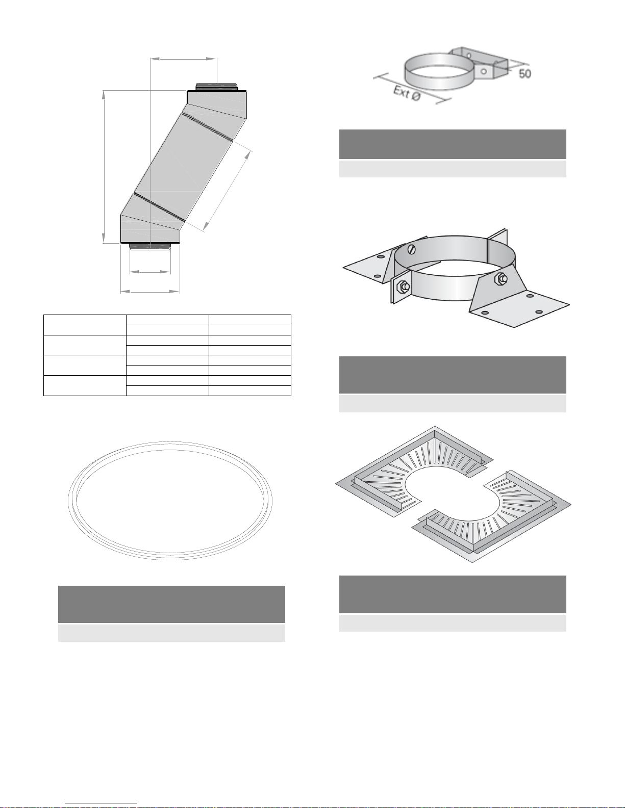
20
Double 30° Bend and straight pipe length
960 Eff pipe
A
1061
B
542
460 Eff pipe
A
628 B 292
293 Eff pipe
A
483 B 208
160 Eff pipe
A
368 B 142
Viton Seal
Part no. WP02
Internal diameter 125mm.
ø125mm Wall Band (50mm)
Internal/external Code WP/WB50
External diameter 180mm.
Roof Support
Code WP/RS
External diameter 180mm.
Fire stop plate
Code WP/FP
External diameter 180mm.
B
A
Ø125
Ø180
EFFECTIVE LENGTH
Page 21
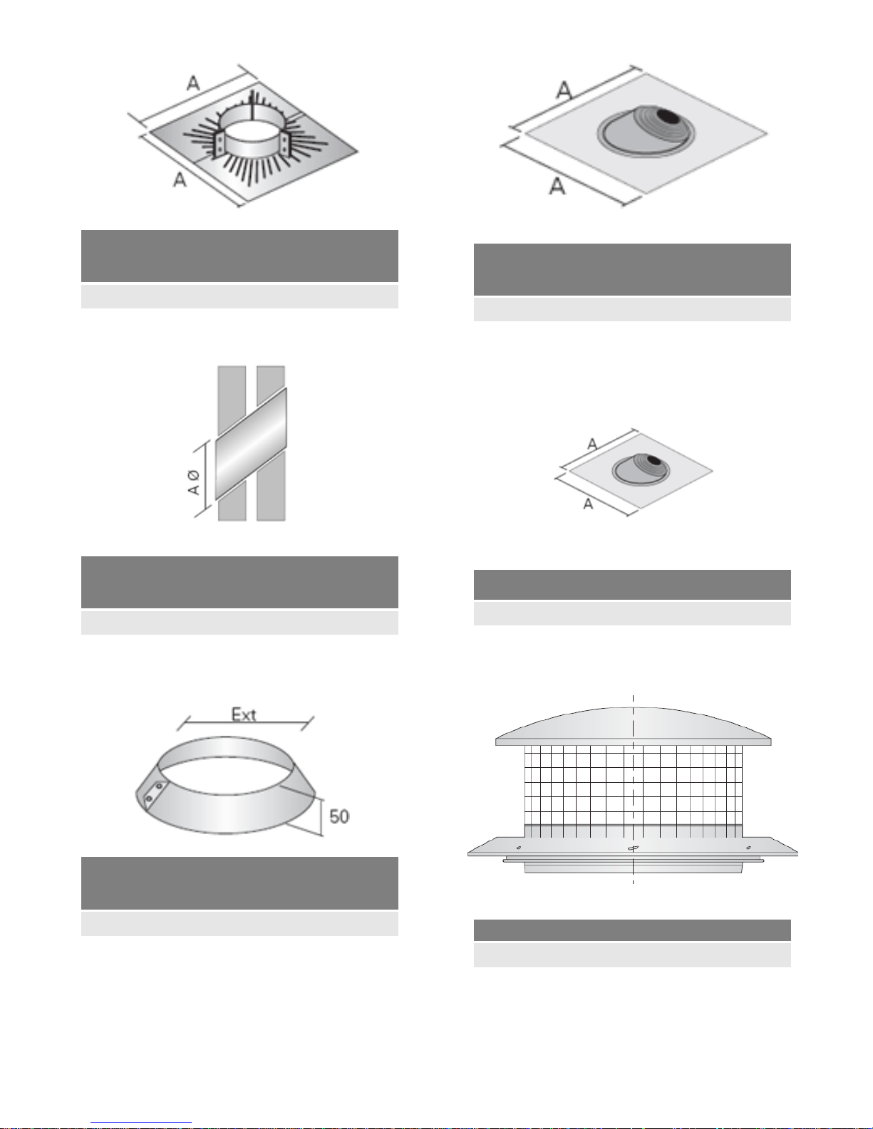
21
Support plate
Code WP/SP
Diameter 180mm.
Support plate
Code WP/SP
External diameter 180mm.
Storm collar Code WP/SC
Diameter 180mm.
Angled Uniflash CodeWP/UF200
Diameter 180mm.
Straight Uniflash
Diameter 180mm.
Rain cap terminal Code WP/RC
Diameter 180mm.
Page 22
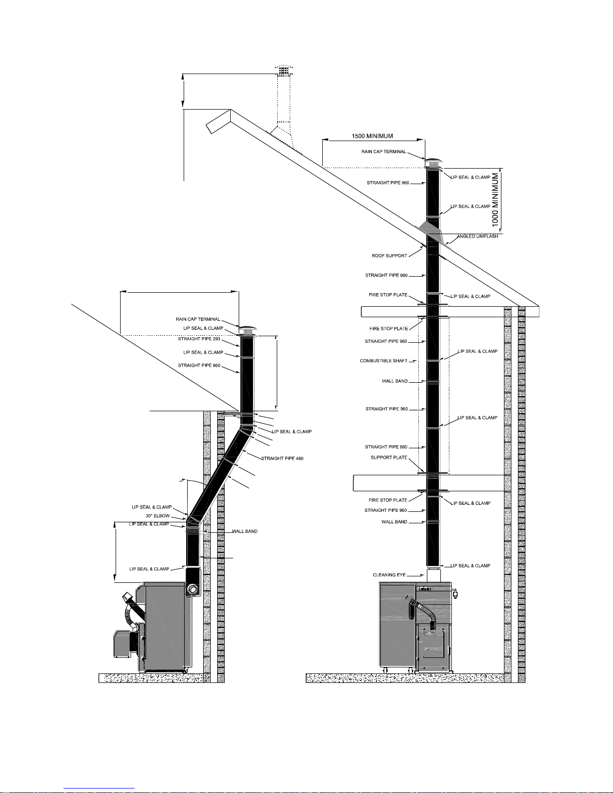
22
6.2 Typical flue installations details.
1000 MINIMUM
600 MINIMUM
30°
STRAIGHT PIPE 460
30° ELBOW
1500 MINIMUM
STRAIGHT PIPE 960
LIP SEAL & CLAMP
LIP SEAL & CLAMP
WALL BAND
WALL BAND EXTENSION
600 MINIMUM
Page 23
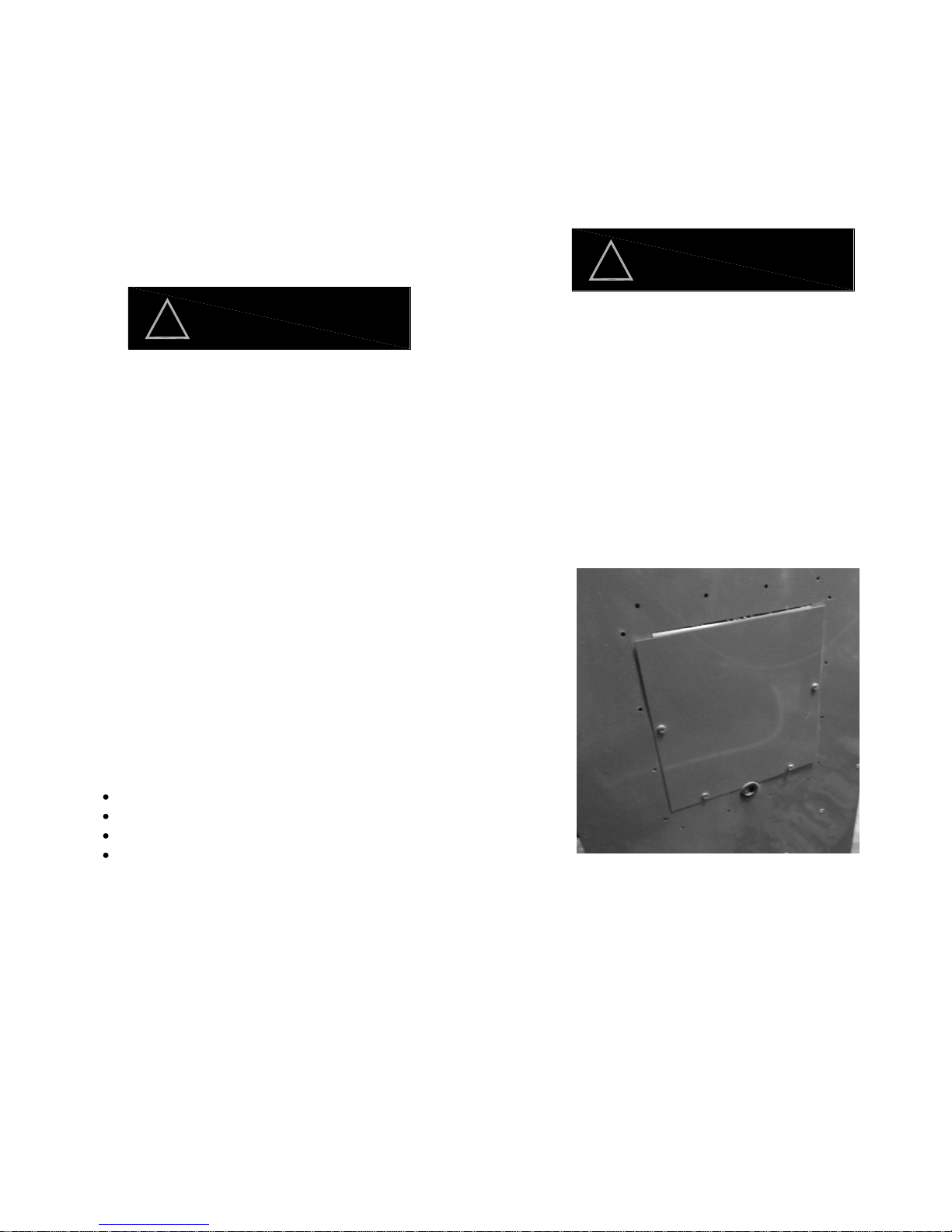
23
The Grant Spira Condensing Wood Pellet boiler requires a
230/240 V ~50 Hz supply. If installed in the Republic of Ireland
the wiring installation must comply with all ETCI rules, if
installed in the UK the installation must comply with current
IEE wiring regulations.
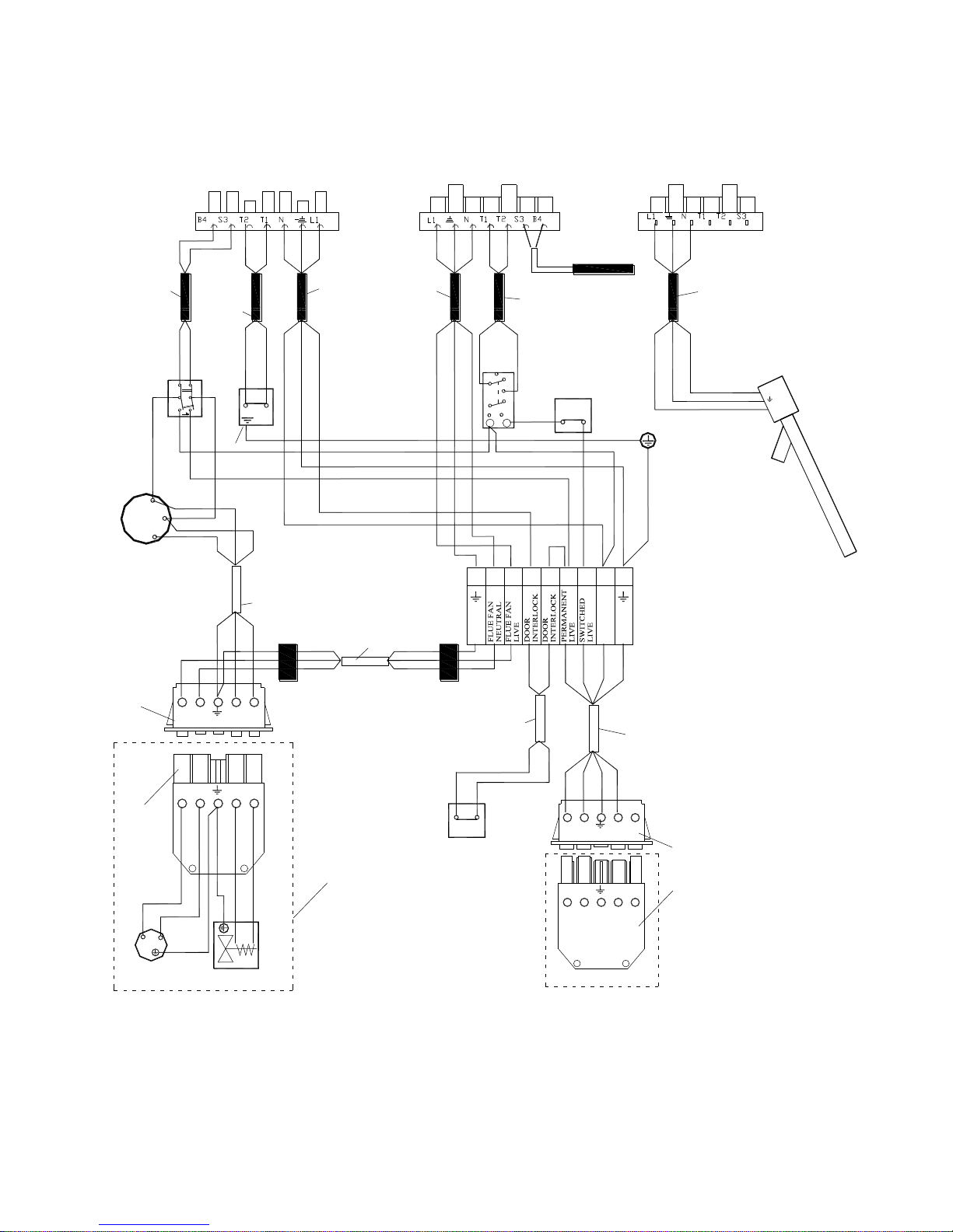
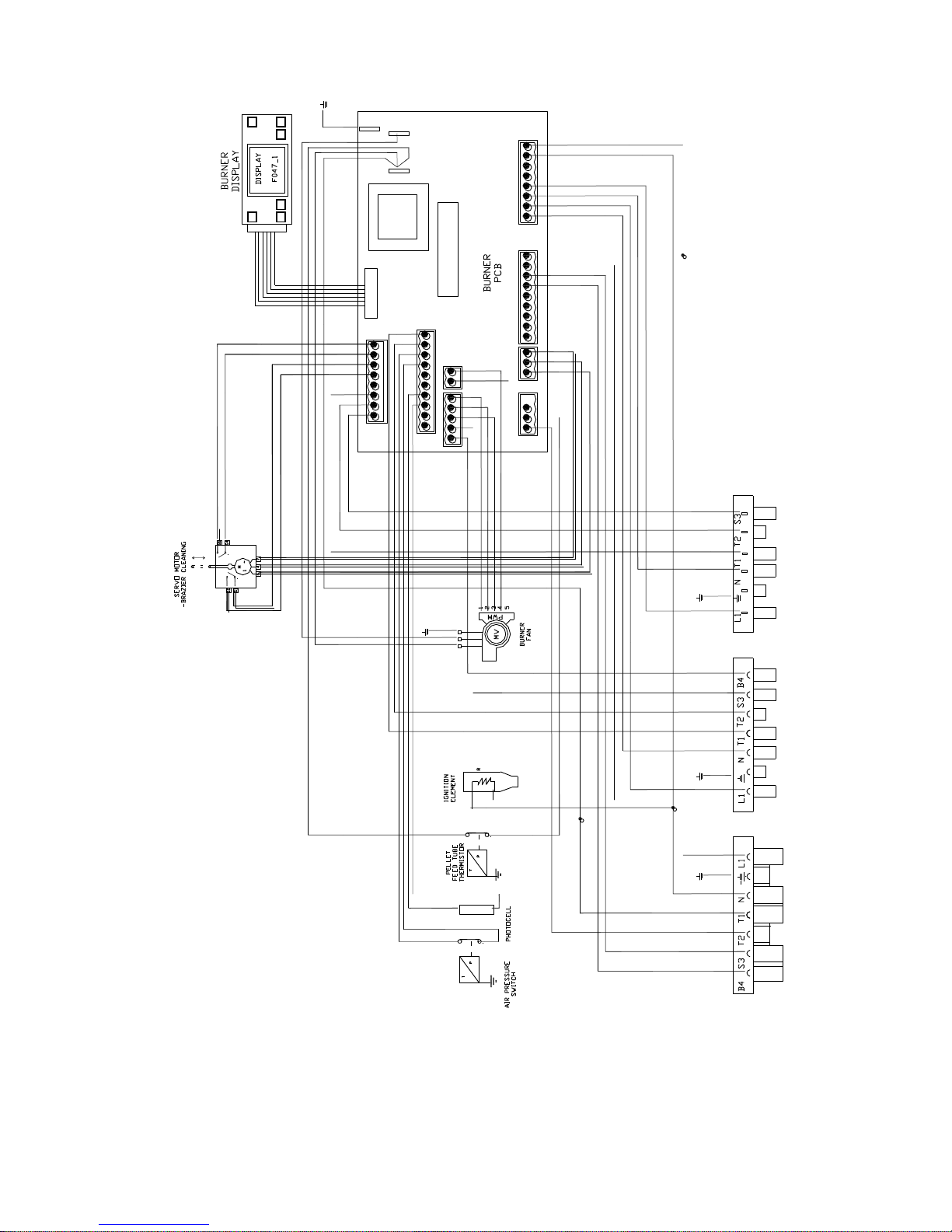
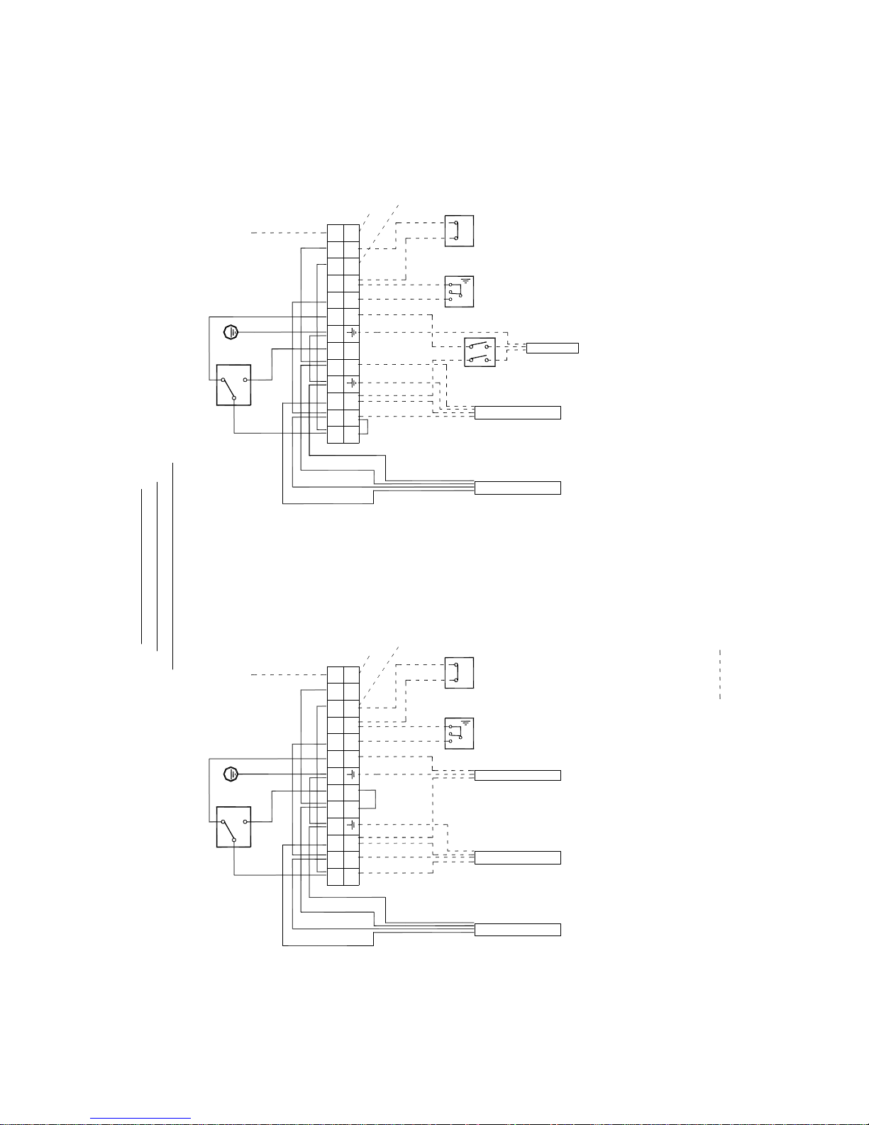
Refer to figure 7.1 to 7.4 for wiring diagrams.
The Grant wood pellet boiler and intermediate hopper
contains electrical switching equipment and must be
earthed; also any bulk hopper system fitted should also
be earthed.
The electrical supply to the appliance and bulk hopper (if
fitted) must only have one common three pole isolator,
providing complete electrical isolation for the permanent live,
switched live and neutral.
The power supply cable should be at least 0.75mm2 PVC as
specified in BS 6500, Table 16.
All the wiring and supplementary earth bonding external to the
boiler must be in accordance with the current I.E.E. wiring
regulations.
Any room thermostat or frost thermostat used with this boiler
must be suitable for use on mains voltage.
In the event of an electrical fault after installation of the boiler,
the following electrical system checks must be carried out.
Short circuit
Polarity
Earth continuity
Resistance to earth
The Grant hopper has the facility to wire in an indicator lamp
(not supplied), this is to indicate to the householder that the
pellets in the hopper have reached its minimum level and the
hopper needs to be topped up. The indicator lamp should be
positioned so it can be easily viewed by the householder. See
figure 7.3
If fitting a bulk hopper then the Grant hopper can control the
feed auger from the bulk hopper to the Grant hopper. When
using a bulk hopper to supply the Grant hopper then a low
pellet indicator lamp can not be fitted to the Grant hopper. See
figure 7.4
7.1 Connecting the power supply
The boiler requires a permanent mains supply and a switched
live supply to control the boiler. Do not interrupt the permanent
supply with any external controls. Refer to figure 7.3and 7.4 to
determine the number of cores required for the cable supply
and for typical control system wiring diagrams.
Before making any electrical connections to the hopper ensure
the following;
a. The flue fan / solenoid plug is fitted to the rear panel
of the boiler.
b. The 7 pin plug and 7 pin socket is fitted to the left-
hand side of the burner.
c. The pellet feed auger plug is fitted to the side of the
burner.
The procedure for connecting the mains supply is as follows;
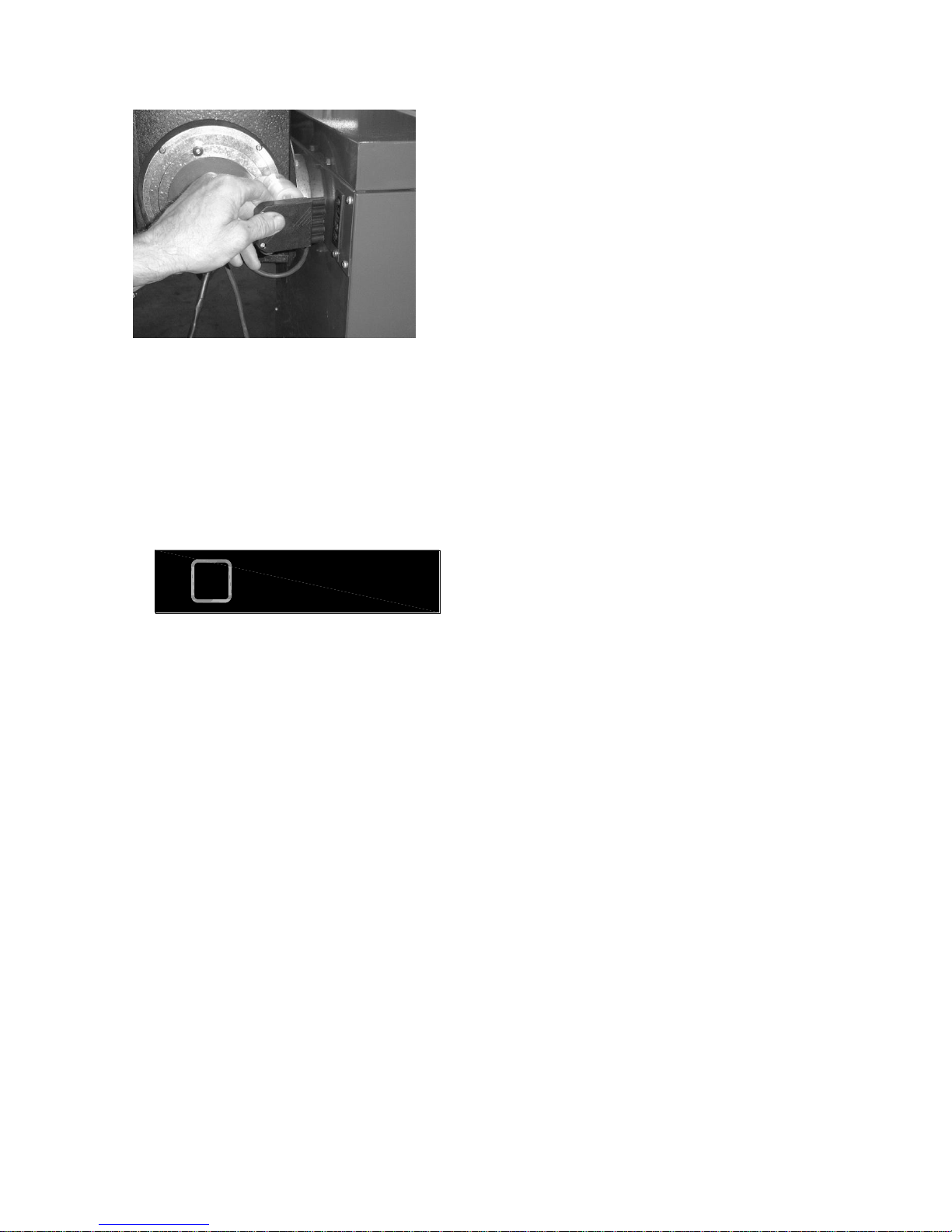
1. Remove the four screws on the rear of the Grant
hopper to gain access to the wiring centre.
Fig 7.1
2. Remove the cable lead and socket from the hopper
wiring centre and insert the socket into plug located
on the top left-hand side of the boiler rear panel
(when viewed from the front). Ensure the cable is
routed so as to prevent damage.
WARNING
!
WARNING
!
7 Electrical
Page 24
24
Fig 7.2
3. Make the electrical connection to suit either of the
following.
-Grant hopper only and low pellet indicator lamp see
figure 7.3.
-Grant hopper supplied by bulk hopper system see
figure 7.4.
The electrical supply to the bulk feed auger will
need a mains isolator to isolate the auger when
the hopper is empty of pellets.
4. Secure all cables fitted in the cable clamp and refit
the panel cover.
7.2 Frost protection
For additional protection of either the entire heating
system, or the boiler and localised pipework, it is
recommended that a frost thermostat be installed; it is
also recommended that it be used in conjunction with a
pipe thermostat to avoid unnecessary and wasteful
overheating of the property. The pipe thermostat should
be located on the boiler return pipe, and set to operate at
25°C. Refer to fig 7.3 & 7.4 for connection details.
NOTE
!
Page 25
25
Fig 7.3
L
E
N
M
L3
L
N
SOLENOID VALVE
FLUE
FAN
BL
BL
G/Y
BR
BR
LIMIT
THERMOSTAT
2
DOOR
ISOLATION
SWITCH
C
NO
COM
SWITCHED LIVE
PERMANENT LIVE
BLK
G/Y
BL
ON / OFF
SWITCH
2
C
N
L
FEED
AUGER
MOTOR
BL
G/Y
Relay
21
A1
22
24
12
14
11
A1
N L2
L1
L3
N
L2
L1
L3
NL2
L1
L3
NL2
L1
BL
BL
G/Y
BLK
BR
RD
G/Y
BL
BR
BOILER
CLEANING
MOTOR
SIX WAY FEMALE
2 core
0.75mm/sq
black
insulation
1400mm
long
3 core
0.75mm/sq
black
insulation
1700mm long
2 core
0.75mm/sq
black
insulation
1600mm long
G/Y
ON / ON SWITCH
MOMENTARY 1
SIDE
PLUG
SOCKET
PLUG
THERMISTOR
1
3
6B
5B
4B
3A
2A
1A
SEVEN WAY FEMALESEVEN WAY MALE
G/Y
N
4
3
12
6 5789
3 core
0.75mm/sq
black
insulation
1450mm long
(no Earth)
3 core
0.75mm/sq
black
insulation
1700mm long
3 core 0.75mm/sq
black insulation
1200mm long
BL -300mm
BL -400mm
BR -500mm
GY -500mm
GY -100mm
RD -320mm
BL -650mm
3 core 0.75mm/sq
white insulation
550mm long fir black
sleeves to inner
insulation
4 core 0.75mm/sq
white insulation
1300mm long
BLK
G/Y
BL
BR
3 core
0.75mm/sq
white
insulation
950mm long
3 core 0.75mm/sq
white
insulation
13000mm long
strip back outer
insulation 100mm
BR
Colour code: BR - Brown, BL - Blue, RD - Red, G/Y - Green/Yellow, BLK-Black, OR - Orange, Y - Yellow
BLK
BLK
BLK
BLK
GRANT WOOD PELLET
6-26 & 9-36
BOILER WIRING DIAGRAM
SOCKET FROM
GRANT HOPPER
FAN BOX
ASSEMBLY
Page 26
26
NO.1 NO.2 NO.3
GRANT WOOD PELLET
6-26 & 9-36
BURNER WIRING DIAGRAM
FIGURE 7.4
Page 27
27
Figure 7.5 Figure 7.6
= INSTALLER WIRING
GRANT WOOD PELLET
INTERMEDIATE HOPPER
-INSTALLER WIRING OPTIONS
REMOVE RED LINK BETWEEN SL2 & L1
AND REFIT INTO SL1 & PL1
MAIN SUPPLY& SWITCHED LIVE
C
NO
NC
G/Y
LOW PELLET CUT-OUT WITH
WARNING LAMP
SUPPLY TO BOILER C/W SOCKET FOR
CONNECTING TO BACK OF BOILER
TO WARNING LAMP
Frost
thermostat
1
2
Nc
C
Pipe
Stat'
C
NO
NC
G/Y
SUPPLY TO BOILER C/W
SOCKET FOR CONNECTING TO
BACK OF BOILER
TO BULK HOPPER AUGER
Frost
thermostat
1
2
Pipe
Stat'
BULK HOPPER FEED
MAIN SUPPLY& SWITCHED LIVE
Nc
C
Supply to CH valve
Switched Live
Permanent Live
Supply to CH valve
with CH valve fitted connect
pipe stat' between L4 & L7
without CH valve fitted connect
pipe stat' between L4 & L5
LIMIT SWITCH
LIMIT SWITCH
N
SL1 SL2
PL1 L1 L2
L3
L4
L5 L6 L7
N
SL1 SL2
PL1 L1 L2
L3
L4
L5 L6 L7
with CH valve fitted connect
pipe stat' between L4 & L7
without CH valve fitted connect
pipe stat' between L4 & L6
Permanent Live
Switched Live
Y
Rd
BlkBrBl
Or
Br
G/Y
G/Y
Rd
Blk
Rd
G/Y
Y
Rd
Br
Bl
Or
Br
G/Y
G/Y
Rd
Blk
Rd
Blk
Two
pole
isolator
switch
Page 28

28
8. Burner
8.1 Burner Operation
The burner controls the pellet feed auger, flue fan, boiler
temperature and also the boiler and brazier cleaning systems.
The burner comes with a display screen and six control
buttons. These buttons are to access the menus and control
the burner functions.
The burner is equipped with a brazier where the combustion of
the wood pellets takes place within the boiler. The self
cleaning device on the brazier activates after the pellet feed
auger run time has exceeded a predetermined set time. The
pellet feed auger run time for brazier and boiler cleaning is set
in the burner menu.
The temperature of the water within the boiler is controlled via
a thermistor to the burner. The thermistor is inserted into the
boiler water jacket and is used by the burner to control the
modulation of the boiler output.
The boiler has a set point temperature. This is the target flow
temperature from the boiler. As the temperature of the boiler
increases and reaches the set point less 5°C the output of the
boiler is reduced by one step. Each subsequent 1°C increase
in boiler temperature reduces the output of the boiler by one
modulation step until the temperature reaches the set point
plus 5°C. At this point the boiler output is „MINIMUM FLAME‟
which is minimum output setting of the boiler. The percentage
increase or decrease in power is calculated on the rate of
temperature change. The sequence of operation is described
in section 8.3.
8.2 Burner Operational Modes
„BOILER WAIT THERMOSTAT‟; (operation code 03) Boiler is
in standby awaiting a switched live input signal and/or the
boiler temperature to drop below the „DELTA RESTART‟
temperature. („DELTA RESTART‟ is the temperature the
burner restarts after maximum temperature has been
reached).
„WAIT PRELOAD BRAZIER‟ (operation code 40) Initial
loading of pellets into the brazier to enable combustion to start.
Activated with a switched live input signal and/or
temperature drops below the „DELTA RESTART‟
temperature.
Deactivated after time exceeds „T08‟.
„WAIT LIGHTING‟ –IGNITION (operation code 41) Period of
time given for pellets to light.
Activated after „Pre load‟ operation is complete.
Deactivated once photocell lux reading exceeds
„FLAME ON‟ setting.
„WAIT LIGHTING‟–FLAME STABILIZATION (operation code
45) Period of time to allow flame stabilize after pellets have
ignited.
Activated after ignition mode.
Deactivated after time exceeds „T13‟
„WAIT LIGHTING‟ –LIGHTING FEED REDUCED (operation
code 42) Period of time intermittent quantities of pellets
supplied to the brazier to increase the flame.
Activated after -„WAIT LIGHTING‟ flame stabilization
mode.
Deactivated after time exceeds „T09‟.
„PELLET BURNER FIRING‟; Power 100% (operation code
13) Flame is fully developed and boiler is operating on full
power.
Activated after –„WAIT LIGHTING‟ lighting feed
reduced mode
Deactivated after temperature is within „TEMP
DELTA‟ range.
„PELLET BURNER FIRING‟; Power (modulating) (operation
code 13) Flame is reduced and boiler output is modulating.
Activated once the boiler temperature is within the
„TEMP DALTA‟ range.
Deactivated after temperature exceeds the „TEMP
DELTA‟ range.
„PELLET BURNER FIRING‟; Power (minimum) (operation
code 13) Flame is reduced and boiler is at its minimum output.
Activated once the boiler temperature exceeds the
„TEMP DELTA‟ range.
Deactivated after the temperature exceeds „TEMP
OFF H2o.
„TURNING OFF BRAZIER‟; (Operation code 14). Burn down
period to remove any pellets remaining in the brazier.
Activated once switched live input signal is switched
off or the boiler temperature exceeds „TEMP OFF
H2o‟ setting.
Deactivated once photocell lux reading has dropped
below the „FLAME ON‟ setting less.
„WAIT POST PURGE‟ (operation code 26) Period of time after
burn down is complete to ensure no unburnt pellets ignite.
Activated after „TUNNING OFF BRAZIER‟ is
complete.
Deactivated after time exceeds „T22‟
Page 29
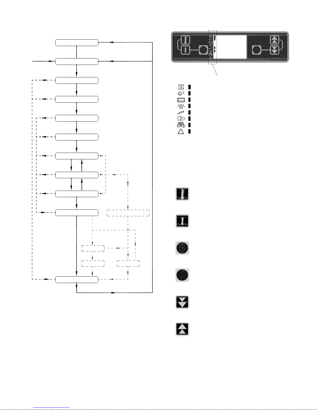
29
8.3 Burner operation sequence
8.4 Burner display screen
8.5 Burner control buttons
The burner has six control buttons, these perform the following
tasks.
WAIT PRE LOAD BRAZIER
40
WAIT LIGHTING
(IGNITION)
WAIT LIGHTING
(FLAME STABILIZATION)
WAIT LIGHTING
(LIGHTING FEED REDUCED)
41
45
42
WAIT BOILER THERMOSTAT
03
PELLET BURNER FIRING
(MAX FLAME)
13
PELLET BURNER FIRING
(MODULATING)
13
PELLET BURNER FIRING
(MIN FLAME)
13
TURNING OFF BRAZIER
14
WAIT POST PURGE
26
TEMP > 'TEMP OFF H2o'
TEMP < 'TEMP
DELTA' RANGE
TEMP > 'TEMP
DELTA' RANGE
TEMP WITH-IN 'TEMP
DELTA' RANGE
TEMP < 'DELTA RESTART' TEMP
& SWITCHED LIVE INPUT ON
TEMP IN 'TEMP
DELTA' RANGE
T > 'T08' PRE LOAD TIME
LUX = 'FLAME ON'
T > 'T13' FLAME STABILIZATION
T > 'T09' LIGHTING CYCLE REDUCED
LUX < 'FLAME ON'
T > 'T22'
TEMP > 'DELTA RESTART' TEMP
OR SWITCHED LIVE INPUT OFF
TEMP < 'DELTA RESTART' TEMP
& SWITCHED LIVE INPUT ON
SWITCHED
LIVE INPUT
OFF
WAIT BRAZIER
IS OPENING >>>>
WAIT BRAZIER
IS CLOSING >>>>
15
15
SWITCHED
LIVE INPUT
OFF
SWITCHED
LIVE INPUT
OFF
SWITCHED
LIVE INPUT
OFF
SWITCHED
LIVE INPUT
OFF
SWITCHED
LIVE INPUT
OFF
WAIT CLEANING
BOILER
03
Auger run time >
'TIME CLEAN BRAZ'
Auger run time >
'TIME CLEAN BOILER
FLASH CLEANING = 1
Auger run time >
'TIME CLEAN BRAZ' &/or
'TIME CLEAN BOILER'
TURNING OFF BRAZIER
14
FLASH CLEANING = 0
Auger run time >
'TIME CLEAN BRAZ'
Auger run time >
'TIME CLEAN BOILER
WAIT PRE LOAD BRAZIER
(PRESSURE SWITCH CHECK)
40
PRESSURE SWITCH CHECK OK
BURNER
POWER
ACTIVATED
FLOW CHART OF OPERATION OF WOOD PELLET BOILER
1
2 3
6
54
!
SET
RESET
SET 75°C
H2o 60°C
PELLET BU
!
= Boiler thermostat calling
= Burner fan operational
= Pressure switch closed
= Ignition element operational
= Feed auger operational
= Photocell lux reading >'Flame On' setting
= n/a
= Error
Active symbols
1
2
3
SET
Normal Mode; Increase temperature set point by 1°C
6
5
4
RESET
Button no. 1
Menu Mode; Scroll up.
Normal mode; Decrease temperature set point by 1°C
Button no. 2
Menu mode; Scroll down.
Button no. 3
Menu mode; Scroll forward.
Normal mode; Reset fault
Button no. 4
Menu mode; Scroll back.
Button no. 5
Menu mode; Decrease parameter value
Button no. 6
Menu mode; Increase parameter value.
Page 30
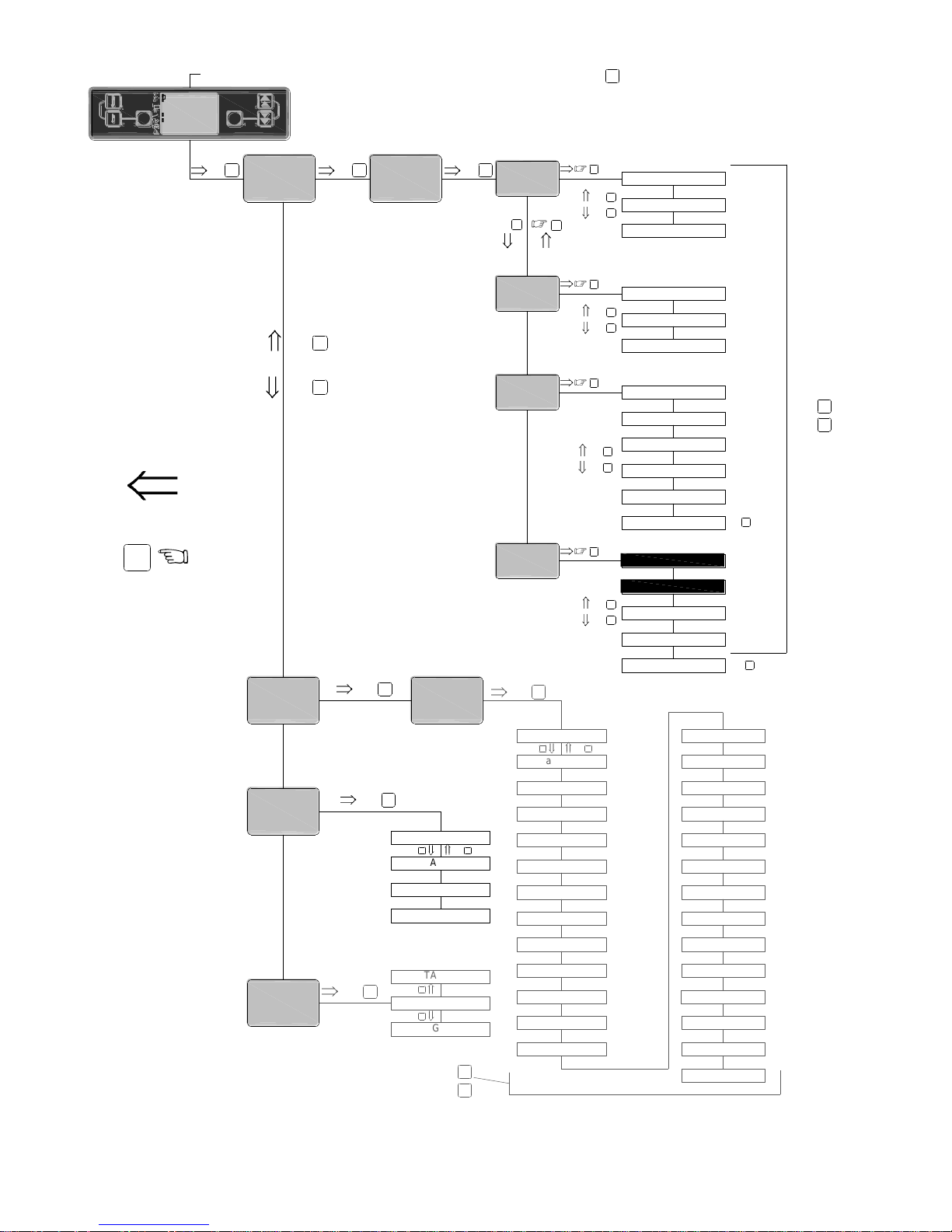
30
8.6 Burner menu navigation chart and factory default settings
LUX %
STEP AUTOMA
VIEW CLE BRAZ
VIEW CLE BOIL
T01 n/a
T02 n/a
T03 n/a
T04 n/a
T05
T07 n/a
T12 n/a
T14 n/a
T16
T24 n/a
FLAME ON
TEMP DELTA
TEMP OFF H2o
DELTA RESTART
TIME LOAD MAX
TIME PAUSE
TIME PAUSE MIN
TIME CLEAN BRAZ
TIME CLEAN BOILER
TIME CLEAN PERIOD
FLASH CLEANING
POWER LIGHTING
POWER TEST
LOAD DEFAULT
HOURS SERVICE
menu 1-4
INSTAL
FLAME OFF
FLAME % MIN
LANGUAGE
RESET SERVICE
X
= BURNER CONTROLS BUTTON
menu 2-4
menu 4-4
FAN
menu 3-4
INSTAL
4
CODE
SETUP
H2o
POWER
PELLET
CLEAN
>
1
2
ITALIAN
ENGLISH
Time (MIN) between
cleanings -Brazier
T17
Time (MIN) between
cleanings -Boiler
T18
Time (SEC) -boiler
cleaning operation
T21
Time pause
min flame (SEC)
max flame (SEC)
time pause
T06
firing (SEC)
time load
T08
time (SEC)
pre-load
T09
reduced (SEC)
time lighting cycle
T10
lighting (SEC)
time load
T11
lighting (SEC)
time pause
T13
(SEC)
flame stabilization
2.5
65.0
120.
4.0
15.0
10.
240
240
60.
5°
80°
5°
2.5
240
240
60
1
500
17
26
100
T22
Time post
purge(SEC)
60.
TO RE-LOAD
FACTORY
SETTING
2
1
4
0
0
0
50
0
10
0
200
0
0
10
T19 n/a
MEnu
MANUFACT
INSTAL
1
MEnu
MANUFACT
INSTAL
2
MEnu
VIEW
MANUFACT
3
MEnu
USER
VIEW
4
MEnu
PSW 0
INSTAL
MEnu
PSW 0
INSTAL
3
1
2
1
2
3
1
2
1
2
6
5
6
5
<
>
6
5
<
3
3
3
3
3
3
3
CODE
3
3
3
1
2
1
2
1
2
TO STEP
BACK
SET
RESET
SET 75°C
H2o XX°C
PELLET BU
3
T20
Max time element
on (SEC)
360
6-26 =2.5
9-36 =6.5
6-26 =2.5
9-36 =6.5
6-26 =36
9-36 =43
T23
Flue fan
delay(SEC)
T15
Time (SEC) Brazier
movement cycle
6-26 =17.5
9-36 =25.0
6-26 =17.5
9-36 =25.0
(T17)
(T18)
(T16)
T05
T06
T21
POWER MAXIMUM
POWER MINIMUM
SET POINT RANGE 55°- 75°C
Page 31
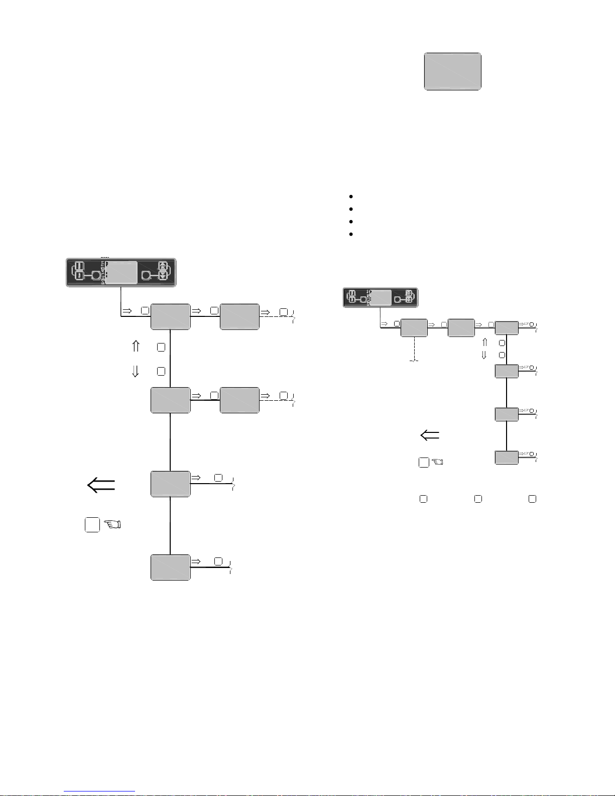
31
8.7 Burner menu
Using the main menu flow chart shown in fig. 8.6 navigate
the menus using the buttons as described in section 8.5.
Each of the four main folders is described in further detail as
follows;
„INSTAL‟, Installer folder, see section 8.3.1
„MANUFACT‟ manufacturer folder, see section 8.3.2
„VIEW‟ folder, see section 8.3.3
„USER‟ folder, see section 8.3.4
Press button „3‟ to open the menu settings. Once the menu
settings option is activated there are four folders to choose
from as shown below.
8.7.1 „INSTAL‟ menu folder
„INSTAL‟ represents the Installer folder. It enables the
installer access relevant parameters for adjustment during
the installation / commissioning of the appliance. Only
accessible with an access code.
The „INSTAL‟ folder has four sub folders;
menu 1-4, H2o
menu 2-4, POWER PELLET
menu 3-4, CLEAN
menu 4-4, SETUP FAN
To access the parameters within the „INSTAL‟ folder
from the main burner display, navigate as follows;
8.7.1.1 „menu 1-4- H2o‟. sub folder contains three
parameters stored within this folder;
a) TEMP DELTA; Temperature range of modulation
each side of set point.
Units -°Celsius.
Default setting 6-26 & 9-36 = 5 (5°C)
b) TEMP OFF H2o; Temperature the burner‟ shuts
down.
Units -°Celsius.
Default setting 6-26 & 9-36 = 80 (80°C)
c) DELTA RESTART; Temperature drop before burner
re-starts.
Units -°Celsius.
Default setting 6-26 & 9-36 = 5 (5°C)
4
MEnu
MANUFACT
INSTAL
1
MEnu
MANUFACT
INSTAL
2
MEnu
VIEW
MANUFACT
3
MEnu
USER
VIEW
4
1
2
3
3
3
TO STEP
BACK
MEnu
PSW 0
INSTAL
CODE
3
MEnu
PSW 0
INSTAL
CODE
Installer folder; Enables the installer access
relevant parameters for adjustment during the
installation / commissioning of the appliance.
Accessible only with an access code.
(See section 8.3.1)
Manufacturer folder; Enables the manufacturer
set parameters required for a specific boiler
range. Accessible only with an access code.
(See section 8.3.2)
View folder; Displays the function or status of
the boiler (See section 8.3.3)
User folder; Allows the user change the
language (See section 8.3.3)
3
3
3
SET
RESET
SET 60°C
H2o 60°C
PELLET BU
MEnu
MANUFACT
INSTAL
1
menu 1-4
INSTAL
menu 2-4
menu 4-4
FAN
menu 3-4
INSTAL
CODE
SETUP
H2o
POWER
PELLET
CLEAN
MEnu
MANUFACT
INSTAL
1
MEnu
PSW 0
INSTAL
3
3
3
3
3
3
1
2
4
TO STEP
BACK
See section
8.3.1.1
See section
8.3.1.2
See section
8.3.1.3
See section
8.3.1.4
6
TO INCREASE
PARAMETER
5
TO DECREASE
PARAMETER
4
TO ACCEPT
PARAMETER
CHANGE
& EXIT
3
SET
RESET
SET 60°C
H2o 60°C
PELLET BU
Page 32

32
Settings in the burner menu‟s below are based on the
boiler using the Grant fixed angle pellet feed auger at 45°
and a motor fixed speed of 8.5 rpm using 6mm „BNM
Premium‟, 6mm „Balcas Brites‟ or 6mm „GWP‟ pellets.
For settings on other brand pellets contact Grant
Engineering.
8.7.1.2 „menu 2-4- POWER PELLET‟. The parameters
stored within this folder are;
a) TIME LOAD MAX; Time the pellet feed auger
operates to deliver pellets to the brazier when the
burner is in max flame mode.
Adjusting this time adjusts the boiler input in max
flame, i.e. the larger the load time, the greater the
input, alternatively the smaller the load time the
lower the input (see table section 2.2.1).
Units 000.0 seconds.
Default setting 6-26 = 25 (2.5 seconds)
Default setting 9-36 = 65 (6.5 seconds)
b) TIME PAUSE MAX; Time between pellet feed auger
operations when the burner is in max flame mode.
Adjusting this time adjusts the boiler input in max
flame, i.e. the larger the pause time, the lower the
input, alternatively the smaller the pause time the
higher the input (see table section 2.2.1).
Units 000.0 seconds.
Default setting 6-26 & 9-36 = 0025 (2.5 seconds)
c) TIME PAUSE MIN; Time between pellet feed auger
operations in min flame. Adjusting this time adjusts
the boiler input in min flame, i.e. the larger the
pause time, the lower the input, alternatively the
smaller the pause time the higher the input (see
table section 2.2.1).
Units 000.0 seconds.
Default setting 6-26 = 175 (17.5 seconds)
Default setting 9-36 = 250 (25 seconds)
Adjusting this setting will also result in the input
during the modulation period being adjusted as
the modulation input is automatically calculated
on the max/min & load/pause settings.
8.7.1.3 „menu 3-4- CLEAN‟
a) TIME CLEAN BRAZ; Total pellet feed auger run
time before burner brazier cleaning operation
activates. (If the burner shuts down immediately or
waits for the next shut down is determined by
„FLASH CLEANING‟ see 8.3.1.3 d.)
Default setting 6-26 & 9-36 =240. (240 Minutes)
b) TIME CLEAN BOILER; Total pellet feed auger run
time before boiler cleaning operation activates.
Default setting 6-26 & 9-36 =240. (240 Minutes)
c) TIME CLEAN PERIOD; Time period boiler cleaning
function is operational once „TIME CLEAN BOILER‟
has elapsed.
Default setting 6-26 & 9-36 =60. (60 Seconds )
d) FLASH CLEANING; Commencement of brazier
cleaning.
1 = Interrupt burner firing, shut down and clean
brazier when time grater than „TIME CLEAN BRAZ‟.
0 = At next burner shut-down, clean brazier when
time grater than „TIME CLEAN BRAZ‟.
Default setting 6-26 & 9-36 = 1
e) HOURS SERVICE; Time lapse period before the
burner screen displays „SERVICE‟. This is to
indicate a service is now due.
Default setting 6-26 & 9-36 = 500 (500 hrs)
f) RESET SERVICE; To cancel the „SERVICE‟ display
on the burner screen after the boiler has been
serviced. Press button 3 („SET‟) follow by button 4
(„RESET)‟ five times to exit the menu.
8.7.1.4 „menu 4-4- SETUP FAN‟.
a) POWER MAXIMUM; Burner fan speed setting when
burner in „max‟ output mode.
Default setting 6-26 = 36
Default setting 9-36 = 43
b) POWER MINIMUM; Burner fan speed setting when
burner in „min‟ output mode.
Default setting 6-26 & 9-36 = 17
c) POWER LIGHTING; Burner fan speed setting when
burner in lighting mode.
Default setting 6-26 & 9-36 = 26
d) POWER TEST; Used to simulate the burner fan
speed for test purposes only. Once the „POWER
TEST‟ is cancelled from the screen the burner fan
reverts to its required operational speed.
e) LOAD DEFAULT; Load factory default settings.
Press button 3 to activate factory default settings.
CAUTION
!
NOTE
!
Page 33
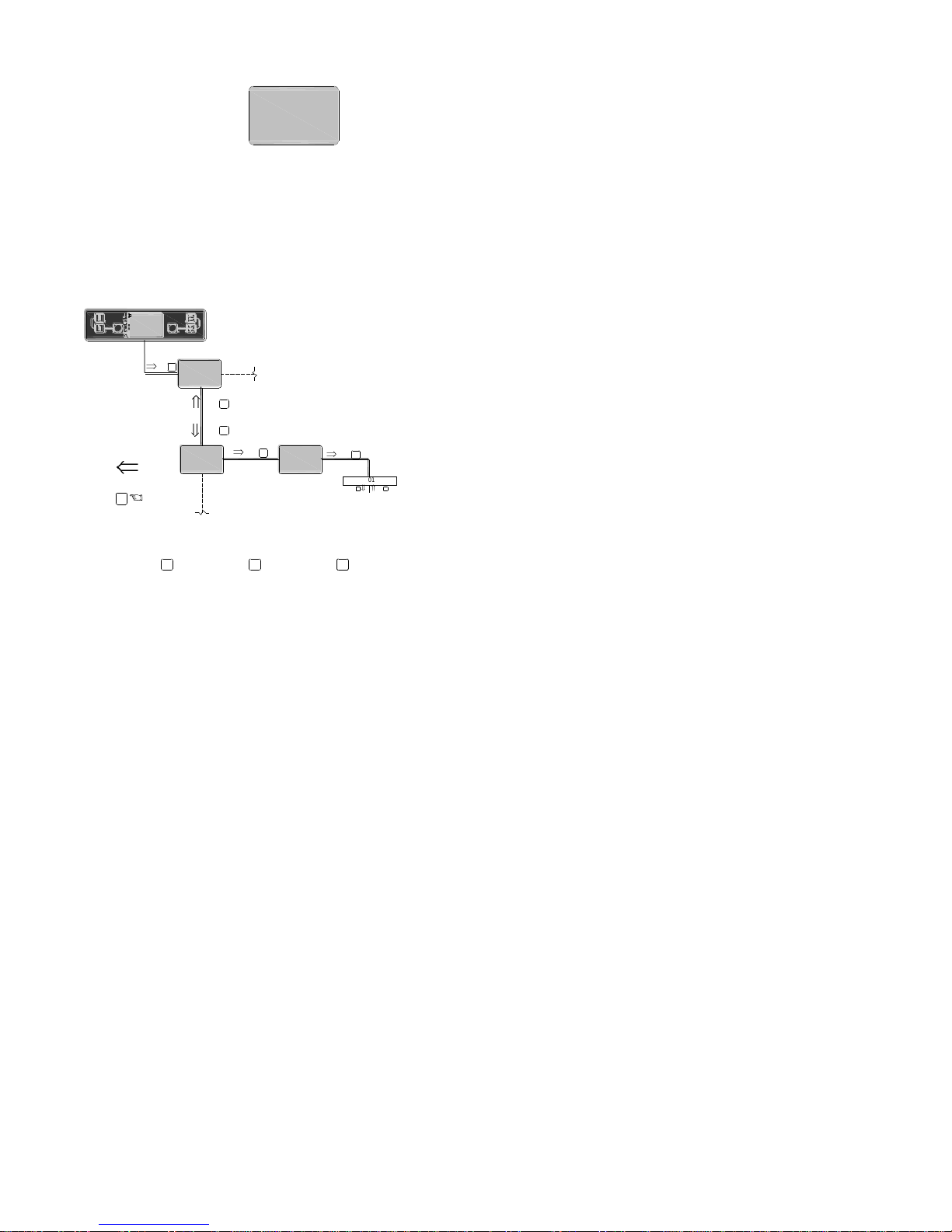
33
8.7.2 „MANUFACT‟ menu folder.
„MANUFACT‟ represents the manufacturer folder, it enables
the manufacturer set parameters required for an individual
boiler. This folder is only accessible with correct access
code. If required the installer may require access to this
folder to modify the boiler input setting.
To access the parameters within the „MANUFACT‟ folder
from the main burner display, navigate as follows;
The „MANUFACT‟ menu folder has 27 parameter settings as
follows;
„T01‟ n/a
„T02‟ n/a
„T03‟ n/a
„T04‟ n/a
„T05‟ TIME PAUSE MAX; Time between pellet feed auger
operations in max flame. Adjusting this time adjusts the
boiler input in max flame, i.e. the larger the pause time,
the lower the input, alternatively the smaller the pause
time the higher the input (see table in section 2.2).
Units 000.0 seconds.
Default setting 6-26 & 9-36 = 0025 (2.5 seconds)
„T06 ‟ TIME LOAD MAX; Time the pellet feed auger
operates to deliver pellets to the brazier in max flame.
Adjusting this time adjusts the boiler input in max flame,
i.e. the larger the load time, the greater the input,
alternatively the smaller the load time the lower the input
(see table in section 2.2).
Units 000.0 seconds.
Default setting 6-26 = 0025 (2.5 seconds)
Default setting 9-36 = 0065 (6.5 seconds)
„T07‟n/a
„T08‟ PRELOAD TIME; Time the pellet feed auger runs
during the lighting sequence to initially charge the brazier
with pellets. If set too low there may be insuffient pellets
to cover the element. If set too high it could cover the
photocell and obscure the view of the photocell.
Units 000.0 seconds.
Default setting 6-26 & 9-36= 0650 (65 seconds)
„T09‟ TIME LIGHTING FEED REDUCED; Period of time
reduced charges of pellets are delivered to the brazier
during light-up.
(„T11‟ x no of loads) +(„T10 x no. pauses) = „T09‟
Activated after pro-load, Deactivate once time has
exceeded time setting for parameter „T09‟.
If set too low the flame may not be sufficiently established
resulting in the flame being smothered when the function
changes to max flame feed. If set too high, pellets could
burn away faster than the pellets were delivered.
Units 000.0 seconds.
Default setting 6-26 & 9-36= 0120 (120 seconds)
„T10‟ TIME LOAD LIGHTING; Time the pellet feed auger
operates to deliver reduced quantity pellets during
„lighting feed reduced‟.
Units 000.0 seconds.
Default setting 6-26 & 9-36 = 0040 (4 seconds)
„T11‟ TIME PAUSE LIGHTING; Time between pellet feed
auger operations during „lighting feed reduced‟.
Units 000.0 seconds.
Default setting 6-26 & 9-36= 0150 (15 seconds)
„T12‟ n/a
„T13‟ FLAME STABILIZATION; Time to allow flame
stabilize during lighting. Activated after ignition mode
(once lux ≥‟FLAME ON‟ setting) Deactivate once time has
exceeded time setting for parameter „T13‟.
If set too low the flame may not be sufficiently established
resulting in the flame being smothered when the function
changes to „lighting flame reduced‟. If set too high, pellets
could burn away resulting in not flame.
Units 0000 seconds.
Default setting 6-26 & 9-36 = 0010 (10 seconds)
„T14‟ n/a
„T15‟ BRAZIER MOVEMENT CYCLE TIME; Time allowed
for the Brazier to complete one movement i.e. open or
close. If the brazier blocks during cleaning, it
automatically attempts one release (i.e. short reverse
followed by forward movement) When a release is
attempted the counter is reset to 0. If the blockage is not
cleared and the brazier is jammed then after 200 seconds
the error „SERVO MOTOR BLOCKED „ is displayed on
the burner screen.
MEnu
MANUFACT
INSTAL
2
T01
4
MEnu
MANUFACT
INSTAL
1
MEnu
MANUFACT
INSTAL
2
MEnu
PSW 0
INSTAL
1
2
12
CODE
3
3
TO STEP
BACK
6
TO INCREASE
PARAMETER
5
TO DECREASE
PARAMETER
4
TO ACCEPT
PARAMETER
CHANGE
& EXIT
3
SET
RESET
SET 60°C
H2o 60°C
PELLET BU
Page 34
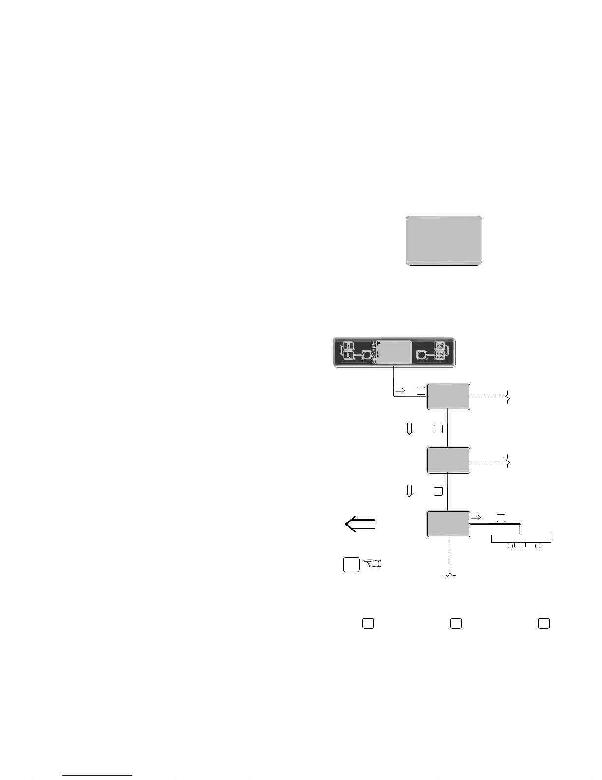
34
Units 0000 seconds.
Default setting 6-26 & 9-36 = 200 (200 seconds)
„T16‟ TIME CLEANING BRAZIER; Total pellet feed auger
run time before burner brazier cleaning operation
activates.
Units 0000 minutes.
Default setting 6-26 & 9-36 = 240 (240 minutes)
„T17‟ TIME CLEAN BOILER; Total pellet feed auger run
time before boiler cleaning operation activates.
Units 0000 minutes.
Default setting 6-26 & 9-36= 240 (240 minutes)
„T18‟ TIME CLEAN BOILER; Time period boiler cleaning
function is operational once „TIME CLEAN BOILER‟ has
elapsed.
Units 0000 seconds.
Default setting 6-26 & 9-36= 60 (60 seconds)
„T19‟ n/a
„T20‟ MAXIMUM TIME ELEMENT ON‟ The maximum
time allowed for the element to remain on. If the photocell
does not read 5 lux within this time, then „FAILED
PELLET LIGHTING IS DISPLAYED‟
Default setting 6-26 & 9-36=360 (360 Seconds)
„T21‟ TIME PAUSE MIN; Time between pellet feed auger
operations in min flame. Adjusting this time adjusts the
boiler input in min flame, i.e. the larger the pause time,
the lower the input, alternatively the smaller the pause
time the higher the input.
Units 000.0 seconds.
Default setting 6-26 = 175 (17.5 seconds)
Default setting 9-36 = 250 (25.0 seconds)
„T22‟ POST VENTILATION; Time burner fan runs once
„TURNING OFF BRAZIER‟ function is complete (i.e. lux <
Turning off brazier‟ setting). Deactivate once time has
exceeded time setting for parameter „T22‟.
Units 0000 seconds.
Default setting 6-26 & 9-36= 60 (60 seconds)
„T23‟ Delayed start on the flue fan start.
Units 0000 seconds.
Default setting 6-26 & 9-36= 0 (0 seconds)
„T24‟ Default setting 6-26 & 9-36= 10 (required for
modulation –do not adjust).
„FLAME ON‟ Flame lux reading to;
a. Activate countdown of T13 to switch off ignition
element during lighting.
b. Deactivate the „Turning off brazier‟ function
when the burner is shutting down.
Default setting 6-26 & 9-36 = 2 (2 Lux)
„FLAME OFF‟ ; In “PELLET BURNER FIRING” mode if
the flame Lux value is less than the „FLAME OFF‟ setting
for 15 seconds, then error „FAILED PELLET LIGHTING‟
is displayed and the burner. The burner fan continues to
run.
Default setting 6-26 & 9-36 = 1 (1 Lux)
„FLAME % MIN‟ When combined with the „FLAME OFF‟
setting is the Lux valve required before the fan changes
to high speed in „WAIT LIGHTING MODE‟
Default setting 6-26 & 9-36 = 4 (4 Lux)
8.7.3 VIEW menu folder.
„VIEW‟ folder displays the function or status of the boiler.
To access the menu displays within the „VIEW‟ folder from
the main burner display, navigate as follows;
The „VIEW‟ menu folder has 4 readout displays as follows;
a. LUX % -Light illumination measured by the
Photocell. Readout is instantaneous.
b. STEP AUTO; Each boiler function is allocated a two
digit number. This menu displays the function the
MEnu
VIEW
MANUFACT
3
4
MEnu
MANUFACT
INSTAL
1
MEnu
MANUFACT
INSTAL
2
MEnu
VIEW
MANUFACT
3
2
TO STEP
BACK
3
2
LUX %
1
2
6
TO INCREASE
PARAMETER
5
TO DECREASE
PARAMETER
4
TO ACCEPT
PARAMETER
CHANGE
& EXIT
3
SET
RESET
SET 60°C
H2o 60°C
PELLET BU
Page 35
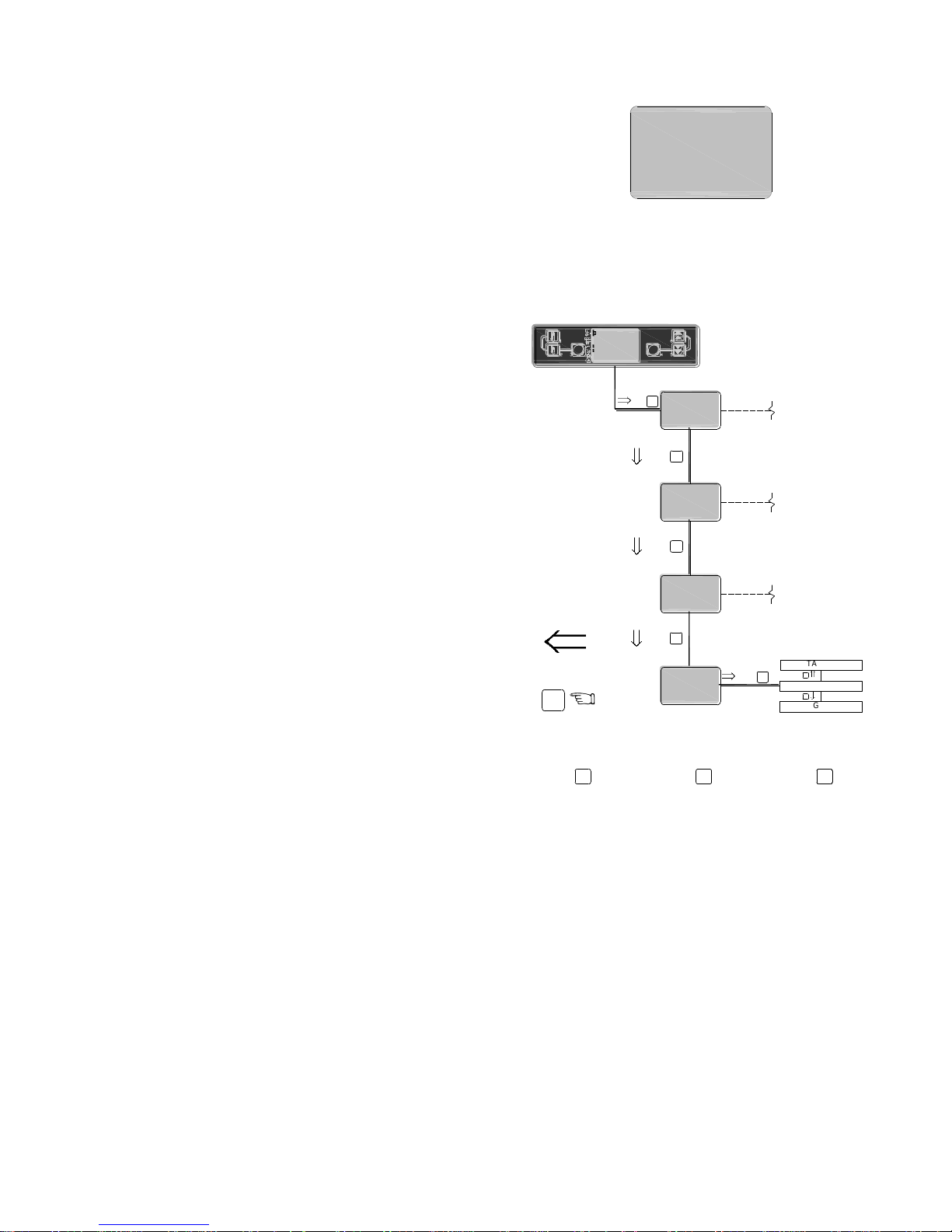
35
boiler is in when viewing. List of functions are as
follows;
03 -WAIT BOILER THERMOSTAT
13 -PELLET BURNER FIRING
14 -TURNING OFF BRAZIER
26 -POST PURGE
29 -AIR PRESSURE ERROR
33 -FAILED PELLET LIGHTING
40 -PRE-LOAD
41 WAIT LIGHTING (IGNITION)
42 WAIT LIGHTING (LIGHTING FEED REDUCED)
45 WAIT LIGHTING (FLAME STABILIZATION)
34 -SERVO MOTOR BLOCKED
15 - BRAZIER IS MOVING FORWARD
15 – BRAZIER IS MOVING BACK
47 – PROBE FAULT
46 – SAFETY CHARGE PIPE THERMOSTAT
46 – SAFETY BOILER THERMOSTAT
c. VIEW CLE BRAZ Total pellet feed auger run time
since brazier last cleaned. When ≥ „„T16‟ brazier
cleaning operation will commence. Resets after
each brazier clean.
d. VIEW CLE BOILER Total pellet feed auger run time
since boiler last cleaned. When ≥ „„T17‟ boiler
cleaning operation will commence. Resets after
each boiler clean.
8.7.4 USER menu folder.
„USER‟ folder; allows the user change the language on the
burner display.
To access the menu displays within the „USER‟ folder from
the main burner display, navigate as follows;
The language options are Italian or English. Once exited, the
language selection shown on screen becomes the displayed
language.
MEnu
USER
VIEW
4
4
MEnu
MANUFACT
INSTAL
1
MEnu
MANUFACT
INSTAL
2
MEnu
VIEW
MANUFACT
3
MEnu
USER
VIEW
4
2
TO STEP
BACK
2
2
LANGUAGE
ITALIAN
ENGLISH
6
5
3
6
TO INCREASE
PARAMETER
5
TO DECREASE
PARAMETER
4
TO ACCEPT
PARAMETER
CHANGE
& EXIT
3
SET
RESET
SET 60°C
H2o 60°C
PELLET BU
Page 36
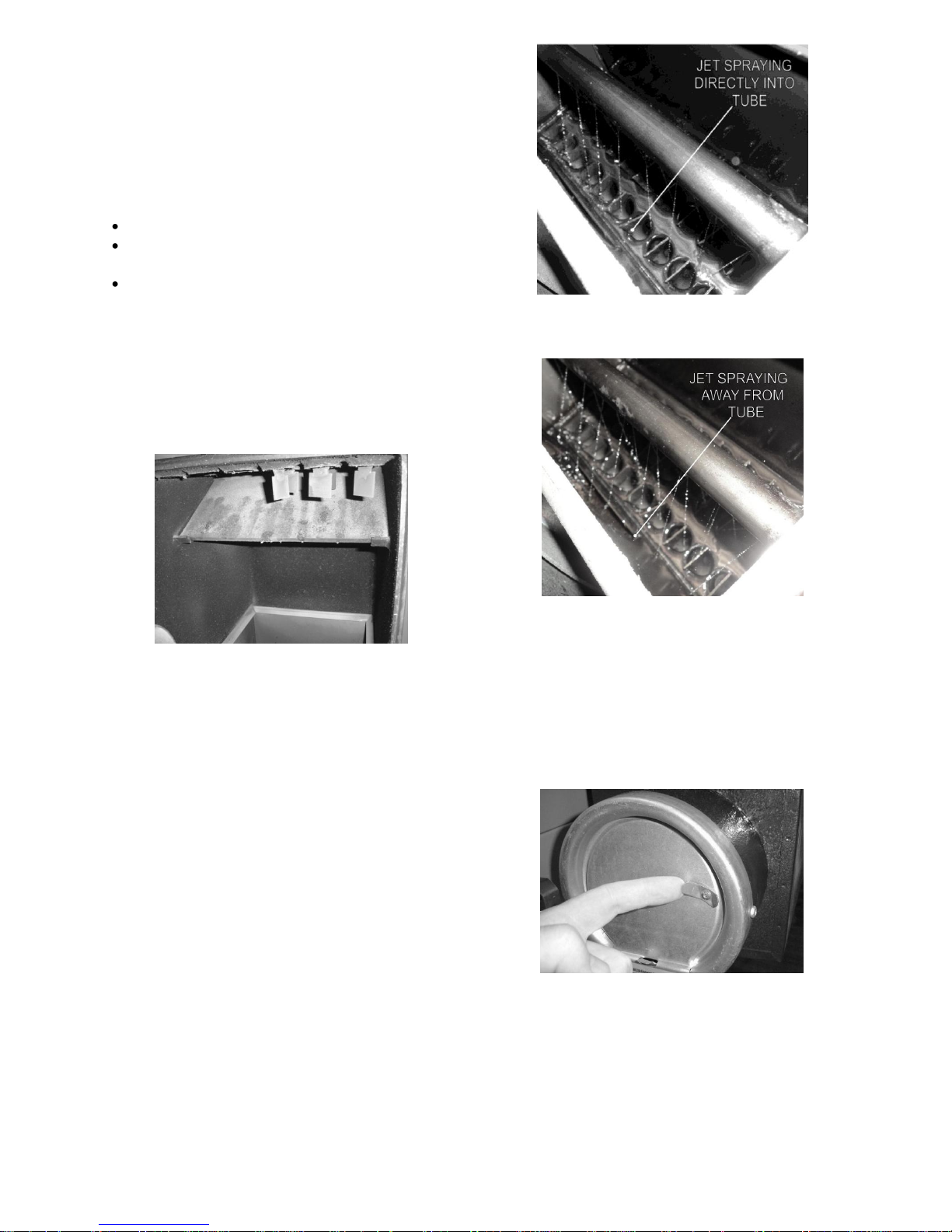
36
9. Commissioning
It is important that the following commissioning
procedure is carried out to ensure safe and
efficient operation of the boiler.
9.1 Equipment required
To carry out a complete and comprehensive
commissioning of the Grant wood pellet boiler
the following equipment is required.
Draught meter.
Flue gas analyser –with a specific “wood pellet”
setting.
Container of at least 1 litre capacity.
9.2 Before switching on
1. Open front access cleaning door and check ash
pan is empty and positioned on the base of the
combustion chamber, check the baffle (located
in the top of the combustion chamber) is secured
correctly on fixing brackets. Close the front
access cleaning door.
Fig. 9.1
2. Check boiler flow and return are adequately
vented. Check boiler and heating system has
been vented (and pressurised if sealed
system).Check the wash down manifold has
been fitted and connected to an uninterrupted
main water supply with all valves open.
3. Remove boiler top panel and boiler top access
doors. Check that the spiral baffles in both the
primary and secondary heat-exchangers are in
place.
4. Test the boiler cleaning function by operating the
momentary „CLEANING‟ „TEST‟ switch on the
boiler control panel.
(a) Check the wash system (located under the top
rear access door) is spraying water directly into
each flue gas tube of the unit. If the water jets
are not spraying directly into the flue gas tubes
adjust the orientation of the wash pipe using the
screw in the right-hand side panel (above the
wash pipe on the right-hand side panel.)
Jets spraying correctly
Fig. 9.2
Jets spraying incorrectly
Fig. 9.3
(b) Check the shaker unit (located under the top
front access door) is operating freely and that
the spirals are moving up and down with an
intermittent sudden vertical motion.
5. Refit the top access cleaning doors in position
and tighten nuts.
6. Check the draught stabilizer is unobstructed and
the stopper is in the fully open position.
Fig. 9.4
7. Check the quality of the wood pellets to be used
(see section 3 Pellet specification and storage).
Do not use wood pellets that have not being
approved By Grant Engineering (IRL) Ltd. for
use with this boiler.
Page 37
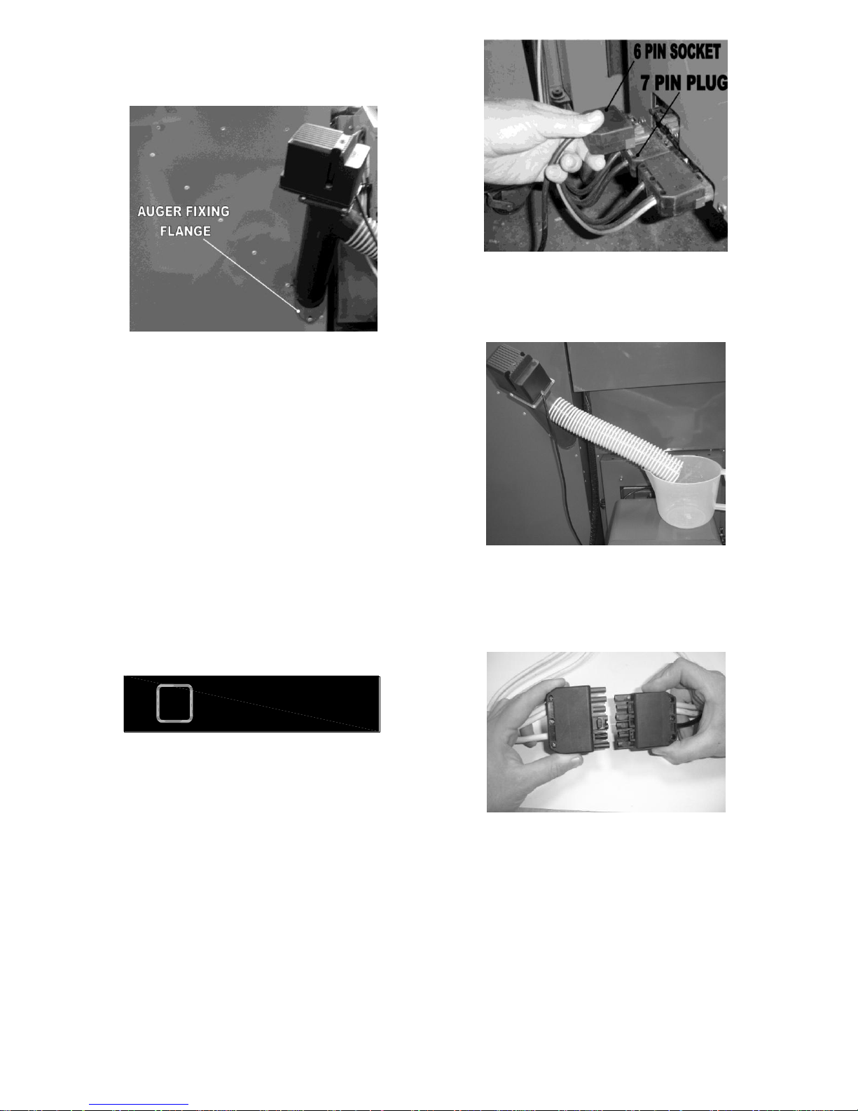
37
8. Check the pellet feed auger is fully inserted into
the Grant hopper and the bolt fitted in the pellet
feed auger fixing flange. Check the hopper is
empty of all objects,
Fig. 9.5
9. Fill the Grant Intermediate hopper with approved
wood pellets.
10. Isolate the electrical power to the appliance and
remove the boiler control panel cover. Check the
overheat thermostat probe and thermistor bulb is
fully inserted in the boiler waterway pocket. (To
view pocket, remove control panel cover). Also
check the condition of cable and capillary, i.e.
not damaged, broken or kinked. Refit the control
panel cover.
11. Set the burner On/Standby switch to On. Check
that all system controls are calling for heat.
12. The burner comes pre-set as shown in table
2.2.1. To confirm the burner output, check „TIME
LOAD MAX‟, „TIME PAUSE‟ & „TIME PAUSE
MIN‟ SETTINGS is correct. See section 8 for
access to the burner menu.
The data table shown in section 2.2.1 is when
using a Grant Intermediate Hopper only.
When using a different hopper to feed the
boiler directly contact Grant Engineering
(IRL) Ltd for advice.
9.3 Priming the pellet feed auger
1. Disconnect the 7 pin plug and 6 pin socket from
the left-hand side of the burner.
Fig. 9.6
2. Disconnect the pellet delivery hose from the
burner and place in a container of at least 1 litre
capacity as shown below.
Fig. 9.7
3. Place the 7 pin plug into the 6 pin socket as
shown below. The feed pellet feed auger will
now run continuously until the plug and socket is
disconnected.
Fig. 9.8
4. The pellet feed auger will prime itself with wood
pellets after a period of 15 to 20 minutes
depending on the pellet feed auger length. Once
there is a continuous flow of pellets from the
pellet delivery hose disconnect the plug and
socket. The pellet feed auger is now fully
primed.
5. Refit the pellet delivery hose into the Burner feed
tube of the burner.
NOTE
!
Page 38
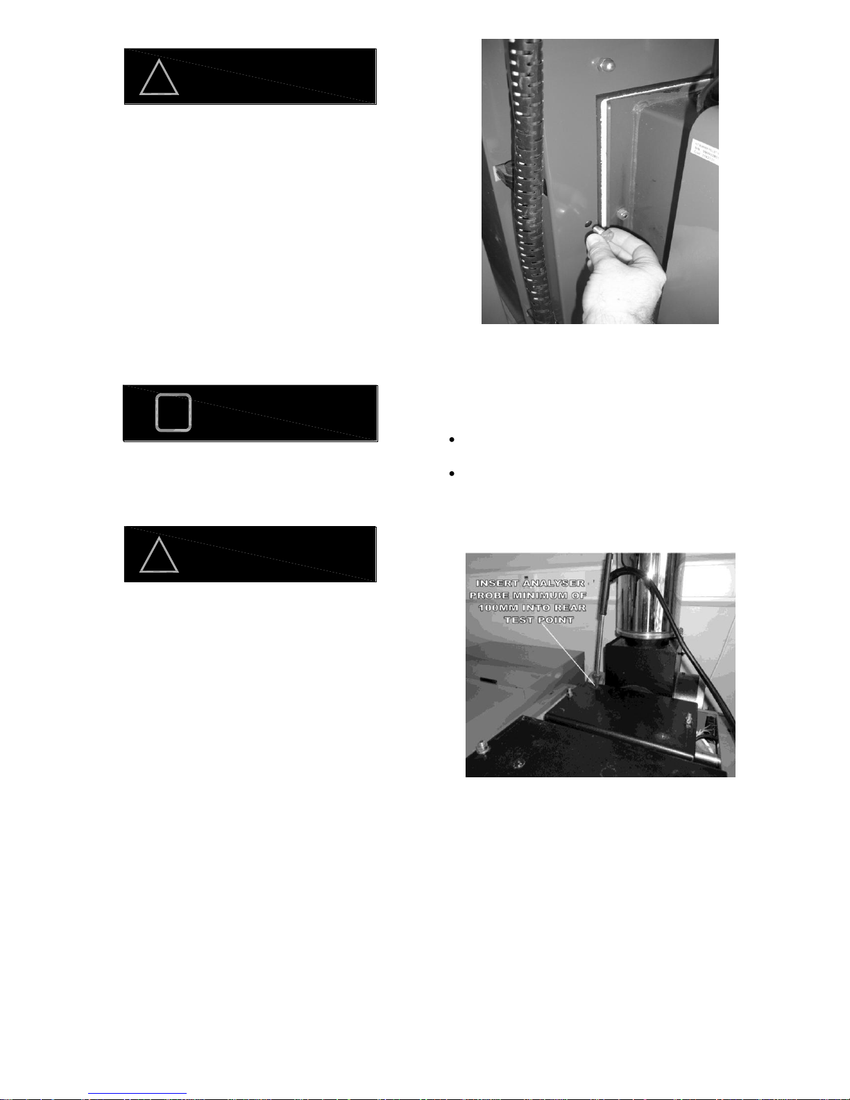
38
Ensure the pellet delivery hose forms an air tight
seal each end and that the hose is not
damage. Leakage of air could cause
increased temperature in the pellet delivery
hose and result in the burn-back thermistor
shutting down the burner .
6. Refit the 7 pin socket and 6 pin plug into the
original position on the side of the burner.
9.4 Lighting the boiler
1. Ensure that system controls are calling for heat.
2. Switch the Burner STANDBY/ON switch on the
boiler control panel to the ON position. The flue
fan will start and pellets will be delivered to the
burner.
If the burner STANDBY/ON switch is switched off
at this stage the pellet feed will stop and the
burner will run through the post purge
sequence before pellet feed starts again.
Do not repeatedly switch on and off the burner at
this stage as a build up of pellets in the
brazier will occur resulting in poor
combustion during lighting.
3. The boiler should now be operational. See
section 8.3 for lighting, running and shut down
sequence of operation.
4. Check the flue fan is operational.
5. Check the combustion chamber draught when
the burner operation mode is „POWER 100%‟
only by inserting the draft meter probe into the
test point located to the left of the burner on the
combustion chamber door.
Fig. 9.9
A draught reading of between 0.1 & 0.15 mbar should
be achieved. To adjust the combustion chamber
draft move position of weights on draft regulator
and add/remove if necessary as follows.
To increase draft – move weight away from
damper or add extra weights (if necessary.)
To decrease draft –move weight closer to
damper or remove weights (if necessary.)
6. Insert combustion analyser probe into rear
test point on top rear access door (secondary
heat exchanger).
Fig. 9.10
7. When the burner is in MAX flame (Power 100%)
operation, adjust the CO2 to achieve a mean
peak reading of between 10 & 12% CO2 over a
minimum of five minute period. To adjust the
CO2 in „MAX flame (Power 100%) access the
burner sub menu „SETUP FAN‟ and adjust
„POWER MAXIMUM‟. To increase the CO2
value, reduce the „POWER MAXIMUM‟ value.
To reduce the CO2 value increase the „POWER
MAXIMUM VALUE‟ .
WARNING
!
NOTE
!
WARNING
!
Page 39
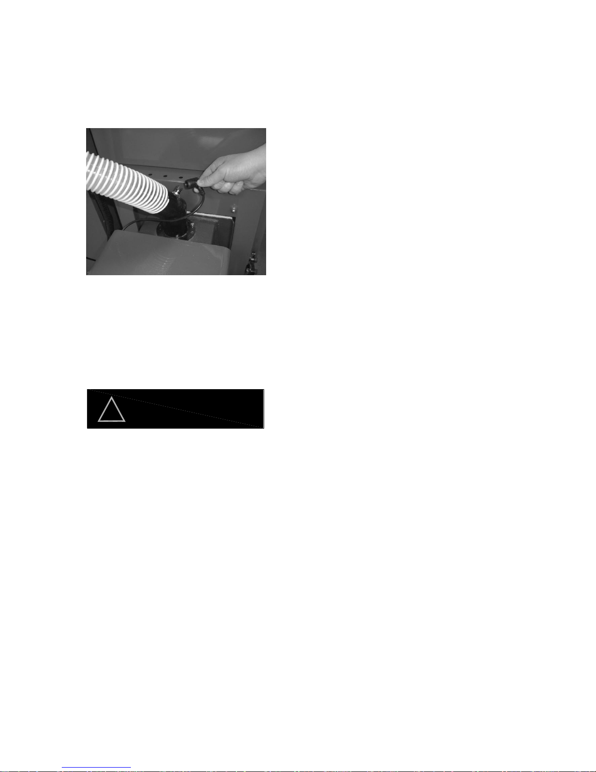
39
8. Also record the combustion analysis details from
the combustion analyser and record the details
on the commissioning sheet.
9. When the „Burner display reads „WAIT PELLET
THERMOSTAT‟, remove the burner burn-back
thermistor from the pellet feed tube. The Burner
display should read „SAFETY CHARGE PIPE
THERMOSTAT‟ once the burn-back thermistor
is disconnected. Refit the thermistor then press
reset the burner will be operational.
Fig. 9.11
10. When the boiler is in „WAIT BOILER
THERMOSTAT‟ mode check the burner door
interlock is operating by opening the combustion
chamber door. The burner led display should
then be switched off, closing the door should
power up the display. This confirms that the door
interlock is operating.
The interlock on the burner door disconnects the
power to the burner to prevent firing when
the door is opened. It does not extinguish the
flame immediately. If the burner door is
opened during the operation of the burner
there can be a large uncontrollable flame
emitted from the brazier.
11. Check the condition of the pellet delivery hose
and ensure it forms an air tight seal each end.
Check for damage and replace if necessary. A
damaged pellet delivery hose can allow a back
draft through the boiler resulting in burner
displaying error „SAFETY CHARGE PIPE
THERMOSTAT‟.
12. If a condensate pump is fitted, check that a
condensate holding tank of at least 40 litres is
also fitted. This is to ensure that when the boiler
cleaning cycle has operated the holding tank can
collect the total volume of the water used in the
wash down and the condensate pump can then
discharge the waste effectively. Also check that
the burner settings „T18‟ (TIME-BOILER
CLEANING OPERATION) is not set greater than
600 (60 seconds) and that „T17‟ (TIME (MIN)
BETWEEN CLEANINGS) is not set less than
240 minutes, as modifying these times could
result in larger and more frequent wash down of
the boiler which could exceed the capabilities of
the tank and condensate pump.
WARNING
!
Page 40
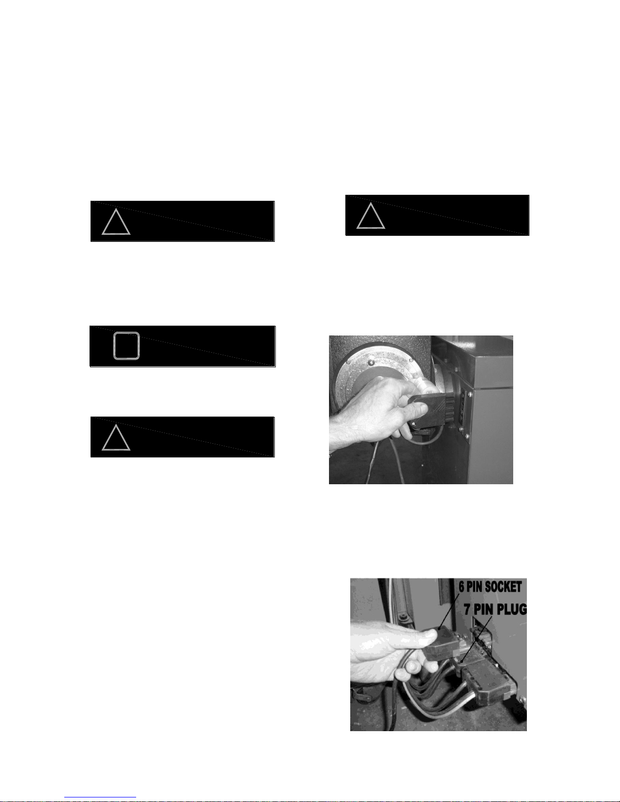
40
10. Boiler Servicing
To ensure a safe and efficient operation of the boiler
the ash pan must be emptied after each 3 tonne of
pellets is used and serviced after each 6 tonne of
pellets is used.
The burner is programmed to display „SERVICE‟ on
the burner display screen once a pre-determined
pellet feed auger run time is achieved. The interval of
the display is programmed by the commissioning
engineer based on the pellet feed auger feed rate and
the time taken to delivery 6 tonne to the boiler.
Servicing and replacement of parts must only be
carried out by a suitably qualified Engineer who
has completed the Grant training course on wood
pellet boilers.
Details of every service should be entered in the
service log, in the boiler hand book.
Before starting any work on the boiler, or pellet
supply please read the health and safety
information given in section 14.
10.1 Checks before servicing
1. Check the flue terminal and ensure it is not
blocked or damaged.
2. If the boiler is used on a sealed central
heating system, check the system pressure,
check the operation of the pressure relief
valve and check the expansion vessel air
charge. The expansion vessel air charge
should be 1.0 bar when the system pressure
is zero.
3. Check the burner parameters setting
correspond with the commissioning sheet
attached to the boiler.
4. Ensure all connections and fittings are
sound. Remake any joints and check
tightness of any fitting that may be leaking.
5. Refill, vent and re-pressurise the system as
necessary.
6. Check that any ventilation openings are
adequate and are clear. See section 6.1.
7. Operate the manual boiler cleaning system
for at least 60 seconds to ensure the boiler is
cleaned down. This is achieved by holding
the boiler cleaning switch in „TEST‟ mode.
Only operate when the burner is not firing.
Before servicing, set the burner switch to
„Standby‟ and after the burner has shut down and
displays „WAIT PELLET THERMOSTAT‟ isolate the
electricity supply by disconnecting the mains
socket fitted in the rear of the boiler as shown in
fig 10.1 below
Fig 10.1
10.2 Cleaning the burner
1. Disconnect the seven pin plug & socket and the
six pin socket from the side of the burner.
Disconnect the pellet delivery hose to the burner
and open the front access cleaning door.
WARNING
!
NOTE
!
WARNING
!
WARNING
!
Page 41
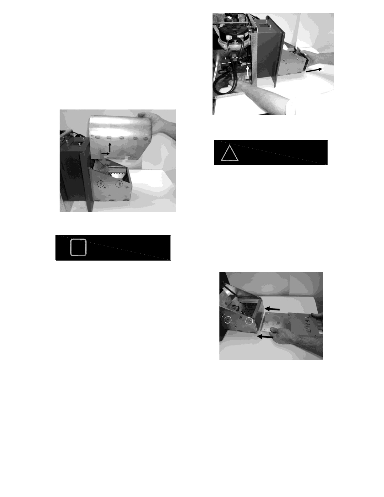
41
Fig 10.2
2. Clean out the brazier and remove all ash
ensuring all air holes are free.
3. Remove the burner cover by loosening the two
M5 screws each side of the burner and lifting off
the cover.
4. Remove the M8 nut each side of the burner and
withdraw the burner from the boiler. Remove the
burner hood by loosening the two M5 bolts
(highlighted below) each side of the brazier.
Slide the hood away from the burner and lift up.
Fig 10.3
After a period of time the end wall of the brazier
hood may distort or show minor cracks. This does
not affect the operation of the burner. The hood
should only be changed if there is considerably
deterioration.
5. Open the brazier manually by pulling up on the
red slider of the electromechanical motor and at
the same time pulling on the end wall of the
brazier as shown in fig 10.4 below. Remove any
ash from within the brazier. Close the brazier
manually by pulling up on the red slider of the
electromechanical motor and at the same time
pushing on the end wall of the brazier.
Fig 10.4
Do not to force the brazier end wall without
disengaging the servo motor release switch.
Failure to release servo motor release switch
WILL damage servo motor gears.
6. Check the clearance of the brazier using the
„Grant‟ clearance gauge. Insert the gauge into
the brazier as shown in fig 10.5. The gauge
should slide in using manual force only.
Fig 10.5
If the gauge does not fit or the clearance is too great;
a. Loosen the two M5 nuts (highlighted above)
each side of the brazier
b. Insert the gauge as shown in fig 10.5.
c. With the gauge in place lightly tighten the M5
screws using minimum force.
d. Ensure the base of the brazier is fully down
by inserting a steel strip between the brazier
chassis and the „Flame plate‟ and lightly
NOTE
!
WARNING
!
Page 42
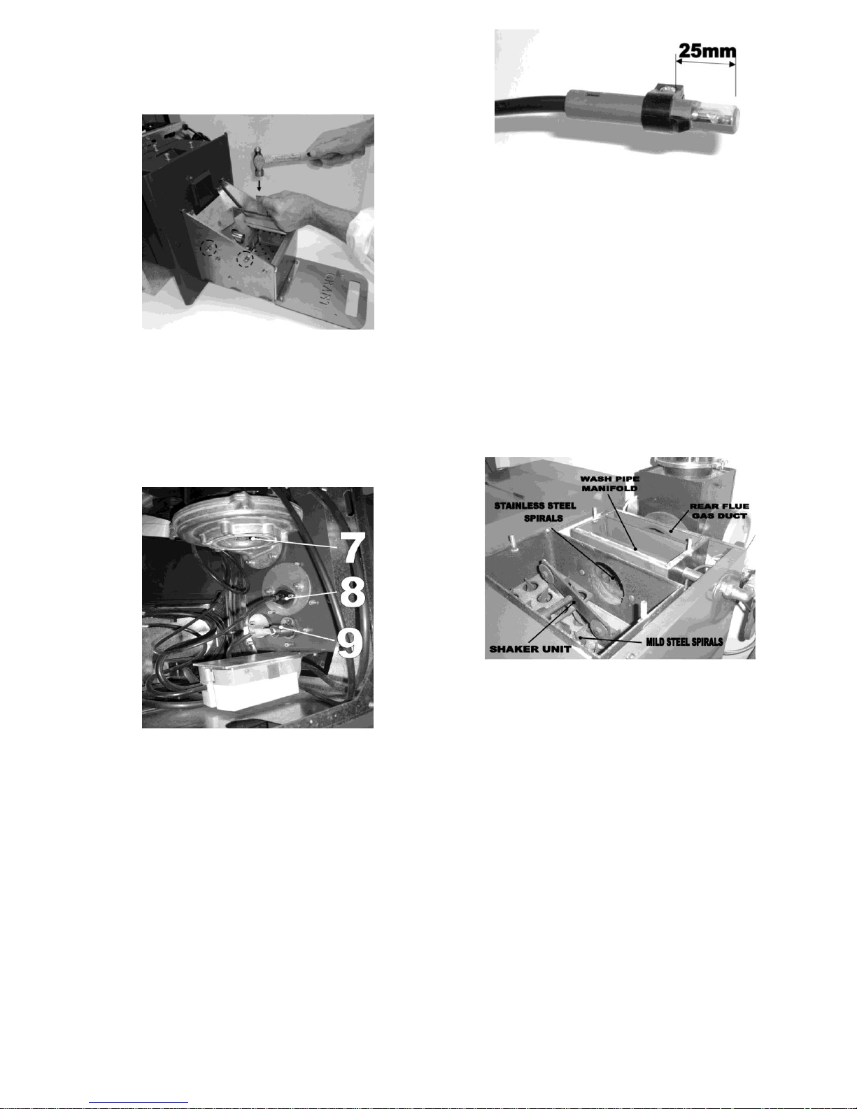
42
tapping each side of the brazier as shown in
fig 10.6, remove the steel strip when finished.
e. Tighten the screws each side.
f. Remove gauge.
Fig 10.6
(b) Check the condition of the heat-shield hood and
replace if necessary.
Fig 10.7
(c) Check the burner fan inlet is clear of debris. If
there is a build-up of debris remove the burner
fan and clean the fan blades and fan housing.
(d) Remove, check and clean the photocell.
Replace if damaged. Ensure the photocell
clamp is fitted 25mm from end as shown in fig
10.8.
Fig 10.8
(e) Remove and check the condition of the heating
element. Replace if damaged.
(f) Also check the pellet feed pipe, clean out if
necessary.
(g) If the burner was removed from the boiler
check the condition of the burner gasket and
replace the gasket if necessary. Refit the
burner and tightening the M8 nut each side.
(h) Refit the burner cover and tighten the two M5
screws each side.
10.3 Cleaning the Boiler & Flue
Fig 10.8
1. Remove the boiler top panel, remove both top
access cleaning covers.
2. Remove the mild steel spirals (from the chamber
at the front of the boiler), examine condition and
clean down or replace if necessary. Remove any
ash on the chamber walls and from underneath
the spiral hangers. Refit spirals in position.
3. Remove the wash system manifold from the rear
chamber of the boiler, clean thoroughly ensuring
all jets are clear and rinse the inside of the wash
system thoroughly to ensure all debris is
removed.
4. Remove the stainless steel spirals (from the
chamber at the rear of the boiler), examine
condition and clean down or replace if
necessary. Remove any ash on the chamber
walls and from the rear flue gas duct.
5. Refit the wash system manifold in place, but do
not tighten at this stage. (The system manifold
Page 43
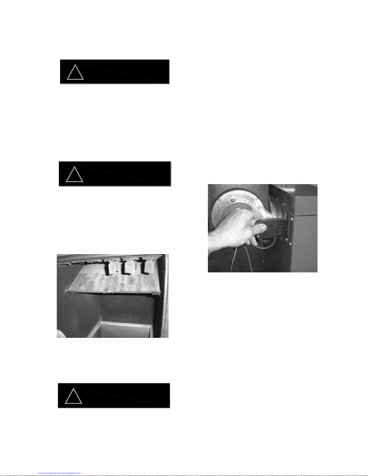
43
needs to be aligned once the unit is powered
up).
6. Remove the flue inspection plate and examine
flue condition. Clean the flue by sweeping it
clean. Chemical cleaners are not recommended.
Failure to maintain a clean flue can result in
the emission of flue gases into the dwelling
or damage from potential fire in the flue.
7. Remove the draught stabilizer from the combined
fan box & flue starter. Open the clean out hatch.
Clean out the combined fan box & flue starter and
the base of the flue (through the opening left by
the by-pass slider). Check fan blades and fan
blade chamber, clean if necessary by removing
the fan.
When cleaning the fan blades ensure a
thorough cleaning is carried out as an
uneven cleaning will result in the fan being
off balance and could possible damage the
fan.
8. Reposition the draught by-pass slider to original
position and refit the draught stabilizer.
9. Remove and clean the baffle (located in the top
of the combustion chamber).
Fig 10.9
10. Remove the ash pan (using the ash pan handles
supplied with the boiler) and dispose of the ash
safely.
Extreme care is required when empting the
ash pan as smouldering ash could be
present and cause serious damage to
persons of property. Ensure the ash is
disposed of in a safe manner.
11. Clean down the combustion chamber and the
combustion chamber door fully.
12. Check the baffle condition and replace if
necessary. Refit the baffle in position ensuring it
is seated correctly on the fixing brackets.
13. Refit the ash pan in the base of the combustion
chamber.
14. Grease the front cleaning door latch mechanism
and close the door.
15. Remove the boiler control panel cover to gain
access to the boiler cleaning mechanism.
Grease the cam edge using high temperature
grease. Refit the boiler control panel. Also
remove the M8 grub screw located on the shaft
of the cleaning mechanism (within the top front
chamber) and recharge the reservoir with high
temperature grease, refit the M8 grub-screw do
not tighten.
16. Power up the boiler by inserting the main
connection into the back of the boiler as shown
in fig 10.10.
Fig 10.10
17. Manually operate the boiler cleaning system by
holding down the „TEST‟ switch on the boiler
control panel.
I. Align the spray from the wash manifold jets
with the pipes in the rear chamber of the
boiler, check all jets are clear. Tighten the
M5 screw located on the fixing flange to
maintain the position of the manifold.
II. Check the shaker unit (located under the
top front access door) is operating freely
and that the spirals are moving up and
down with an intermittent sudden vertical
motion. (If there is no sudden vertical
motion, isolate the power as shown in fig
10.1 and check the condition of the spring
located in the rear of the control panel
replace if necessary).
18. Check the condition of the top access cleaning
covers and replace gaskets and seals if
necessary. Refit the top access cleaning covers
and the boiler top panel.
WARNING
!
CAUTION
!
CAUTION
!
Page 44

44
19. Disconnect the drain trap located on the
condensate drain system from the back of the
boiler. Clean thoroughly and re-fit.
20. Check the condition of the pellet delivery hose
and ensure it forms an air tight seal each end.
Check for damage and replace if necessary. A
damaged pellet delivery hose can allow a back
draft through the boiler resulting in burner
displaying error „SAFETY CHARGE PIPE
THERMOSTAT‟.
21. On the burner menus reset the service time by
pressing the SET button (3) when the burner
display shows RESET SERVICE. See section
8.6.
To ensure safe and efficient operation of the
boiler it is important that re-commissioning
is carried out, refer to Commissioning
instructions 9.4 Lighting the boiler‟.
WARNING
!
Page 45
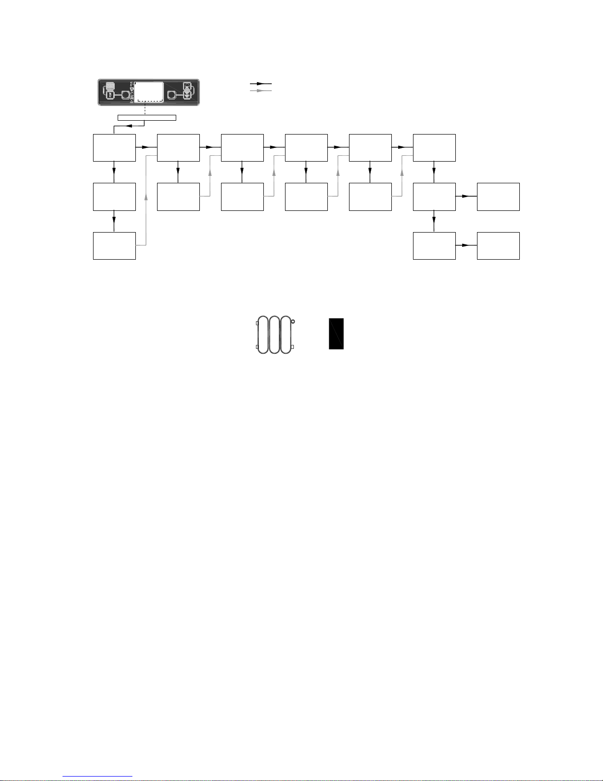
45
11 Fault finding
11.1 Boiler won‟t fire (no error message)
Notes;
1. When the switched live supply to the burner is activated, the burner display shows a cursor highlighted
beside the boiler thermostat symbol, as shown below.
2. Depending on the type of installation, insufficient pellets in the intermediate hopper will result in either of the
following;
a. Intermediate hopper controlling a bulk hopper feed system will not use the low level cut out system, the
burner will display error message „FAILED PELLET LIGHTING‟ when the intermediate hopper has
insufficient pellets.
b. Intermediate hopper using the low level cut out system will switch the boiler to standby mode and the
burner will display „WAIT BOILER THERMOSTAT‟ when the intermediate hopper has insufficient pellets.
3. Refer to diagram in section 7.1.2.
4. Refer to section 7 Electrical.
YES
NO
NO FAULT
-BOILER
WAITING FOR
SYSTEM TEMP.
TO DROP
CURSER BESIDE
THERMOSTAT
SYMBOL OF
BURNER DISPLAY
'BURNER' SWITCH
IN THE 'ON' MODE
OF THE BOILER
CONTROL PANEL
NO
= PRIMARY FAULT
= SECONDARY FOLLOW ON CHECKS
1
2 3
6
54
!
SET
RESET
SET 80°C
H2o 60°C
WAIT BOILE
WAIT BOILER THERMOSTAT
note 1
POSITION
'BURNER' SWITCH
IN 'ON' MODE
YES
NO
FILL HOPPER
SUFFICIENT
QUANTITY OF
PELLETS IN
HOPPER
YES
NO
TIMER AND OR
ROOM STAT
CALLING
ACTIVATE
TIMER AND OR
ROOM STAT
YES
NO
CHECK POWER
TO L2 OF
SUPPLY LEAD IN
REAR OF BOILER
CHECK
SWITCHED LIVE
SUPPLY TO
BOILER
(& HOPPER)
YES
NO
CHECK
CONTINUITY
BETWEEN T1 &
T2 OF BURNER
PLUG NO. ?
CHECK POWER
ACROSS BOILER
ON/OFF SWITCH
YES
CHECK POWER
AT 21 & 24 OF
BOILER RELAY
WITH COIL
ENERGIZED
NO
REPLACE
SWITCH
NO
REPLACE
RELAY
note 2 note 3
note 4
note 4
note 4
H2o TEMP>SET
POINT MINUS
DELTA RESTART
TEMP.
YES
Page 46
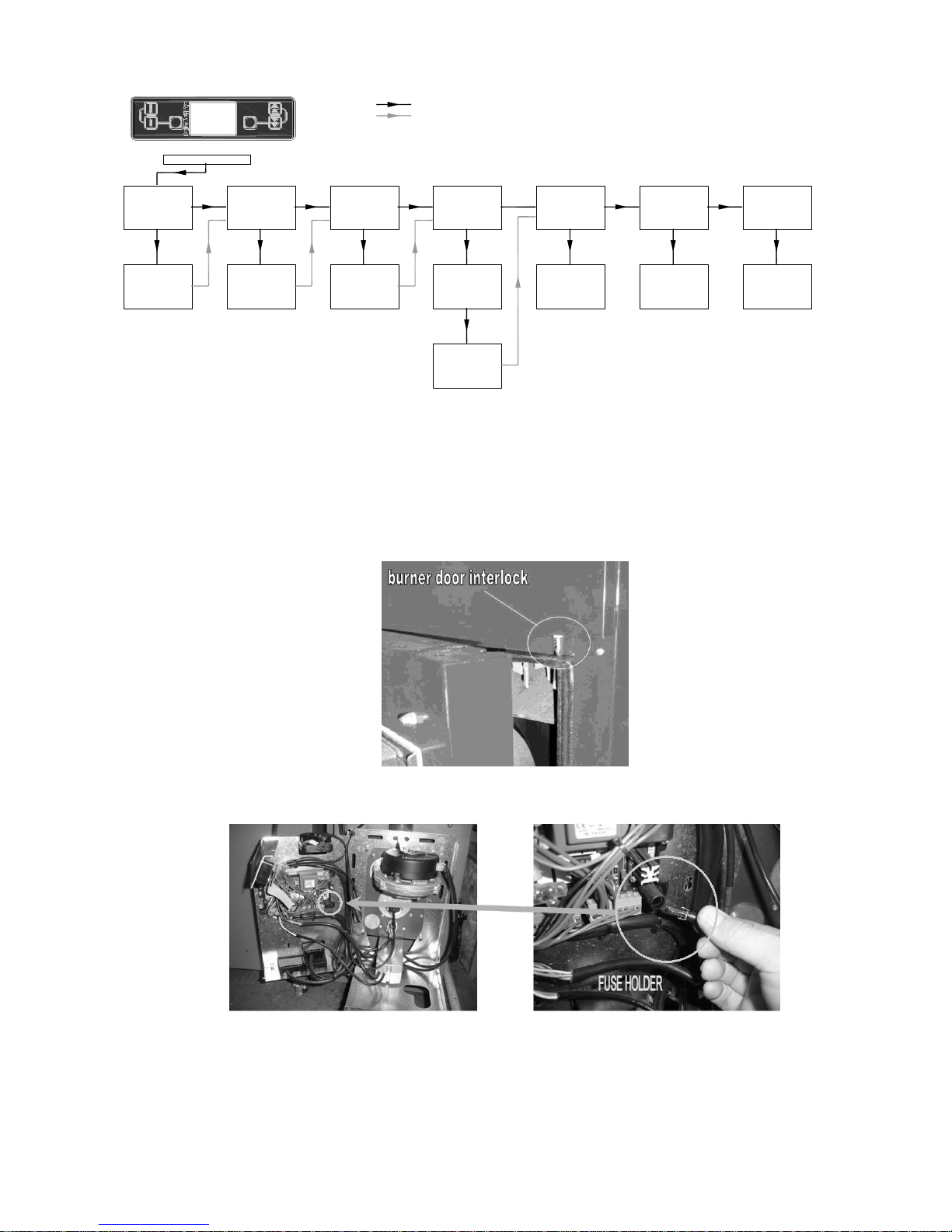
46
11.2 Boiler won‟t fire (Blank screen)
Notes;
1. The burner door is fitted with a safety interlock. Once the door is opened all power is disconnected to the
burner.
2. See diagram shown in section 7.1.
3. See diagram shown in section 9.3.1
4.
Diagram showing burner door interlock
5.
Diagram showing the fuse holder located within the burner PCB enclosure.
Fuse type F5AL250V
NO
YES
CLOSE
BURNER DOOR
CHECK
BURNER
DOOR CLOSED
CHECK POWER
TO L1 OF
SUPPLY LEAD IN
REAR OF BOILER
NO
CHECK
ELECTRICITY
SUPPLY TO
BOILER
1
2 3
6
54
!
SET
RESET
BLANK SCREEN
YES
NO
FIT PLUGS
YES
CHECK POWER
TO L1 OF PLUG ?
IN BURNER
NO
CHECK DOOR
MICRO-SWITCH
OPERATIONAL
CHECK BURNER
FUSE FOR
CONTINUITY
NO
REPLACE
BURNER FUSE
YES
CHECK RIBBON
CABLE FITTED
TO BACK OF
DISPLAY
YES
REPLACE
BURNER PCB
NO
REFIT RIBBON
CABLE
NO
REFIT PCB &
REPLACE
DISPLAY UNIT
NO
REPLACE
FAULTY DOOR
SWITCH
CHECK BURNER
PLUG
CONNECTIONS
CORRECT
note 2
note 2
note 3 note 3
note 4
note 5
note 1
= PRIMARY FAULT
= SECONDARY FOLLOW ON CHECKS
Page 47
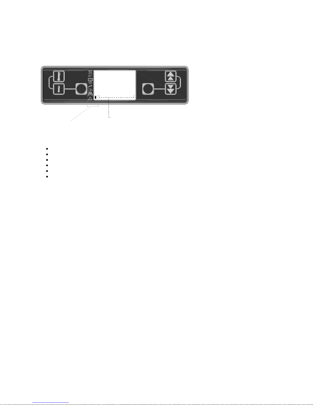
47
11.3 Error messages
When a fault occurs with the burner, the burner display screen displays a block to the right of the error symbol as
shown below. The lower area of the text screen also displays a message of the fault that occurred.
List of possible error messages;
FAILED PELLET LIGHTING, Step Auto function -33 See section 11.1
SERVO MOTOR BLOCKED, Step Auto function -34 See section 11.2
SAFETY CHARGE PIPE THERMOSTAT, Step Auto function -46 See section 11.3
SAFETY BOILER THERMOSTAT, Step Auto function -46 See section 11.4
PROBE FAULT, Step Auto function -47 See section 11.5
AIR PRESSURE ERROR, Step Auto function -29 See section 11.6
1
2 3
6
54
!
SET
RESET
SET 60°C
H2o 60°C
FAILED PEL
FAILED PELLET LIGHTING
Error symbol
Page 48
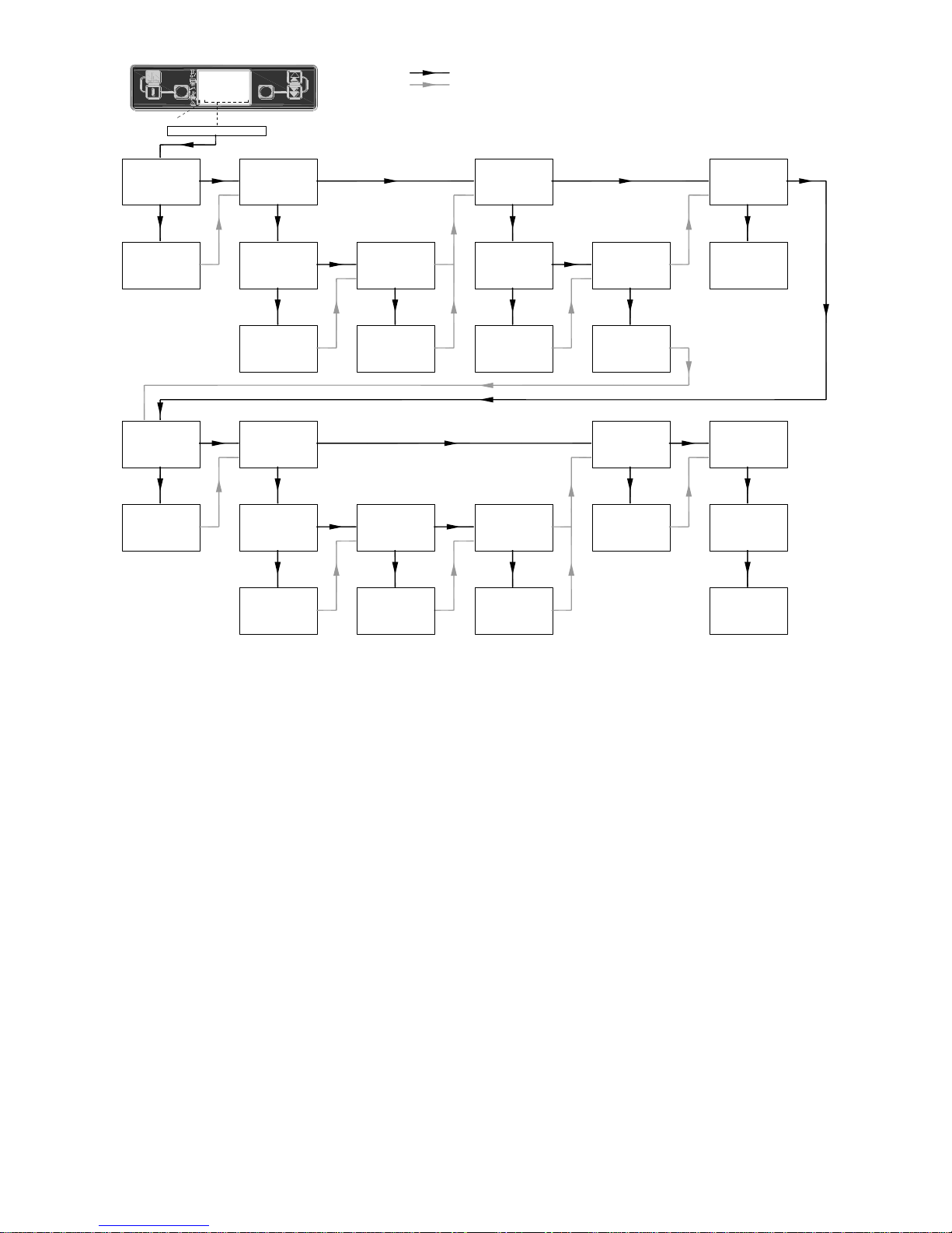
48
11.3.1 FAILED PELLET LIGHTING
Notes;
1. Depending on the type of installation insufficient pellets in the intermediate hopper will result in either of the
following;
A. Intermediate hopper controlling a bulk hopper feed system will not use the low level cut out system, the burner
will display error message „FAILED PELLET LIGHTING‟ when the intermediate hopper has insufficient pellets.
B. Intermediate hopper using the low level cut out system will switch the boiler to standby mode and the burner
will display „WAIT BOILER THERMOSTAT‟ when the intermediate hopper has insufficient pellets..
2. Clinker is classed as solidified ash containing sand particles that the burner cleaning system is unable to
remove. Clinker is caused by using unsuitable pellets.
3. Refer to section 8.7.1.3a. menu folder „TIME CLEAN BRAZ‟
4. The ignition element is operational in Functions 40, 41 & 45. see section 8.7.3.b.
5. Check continuity across the ignition element when the element is disconnected.
6. Refer to section 8.7.2 „MANUFACT‟ menu folder.
7. When in function „41‟ (ignition), if after a time of „T20‟ & photocell Lux valve doesn‟t get to 5 lux, then the error
message „FAILED PELLET LIGHTING‟ is displayed. Max „T20‟ = 750 See section 9.4.10, how to check preload.
8. See section 8.7.2, how to adjust the „preload‟ setting.
9. „T13‟ is the „FLAME STABILIZATION‟ period. This is the period allowed for the flame to establish. Too short a
time prevents the flame from developing or too long a period allows the flame burn-up the fuel. Ideal time is 2
minutes or a „T13‟ setting of 20. If the flame drops below 5 lux in this function then error message „FAILED
PELLET LIGHTING‟ is displayed.
10. See section 8.7.3.a VIEW menu folder. To display the photocell value view „LUX %‟.
NO NO
CHECK PELLETS
DELIVERED TO
BURNER
YES
FILL HOPPER
&
PRIME AUGER
CHECK AUGER
ROTATING
NO
CHECK AUGER
MOTOR
POWER &
COUPLING
SUFFICIENT
QUANTITY OF
PELLETS IN
HOPPER
CHECK HOPPER
OUTLET FOR
DUST OR
BLOCKAGE
YES
YES
CLEAN OUT
HOPPER AND
PRIME AUGER
CHECK (40)
PRE-LOAD
PARAMETER
CORRECT
YES
NO
CHECK AUGER
PRIMED
FULLY
YES
RE-PRIME
AUGER
ADJUST
PRE-LOAD
PARAMETER 'T08'
UN-BURNT
PELLETS
IN THE
BRAZIER
NO
YES
CLINKER IN
BRAZIER
NO
YES
CLEAN BRAZIER &
CHECK PELLET
QUALITY, ADJUST
BRAZIER
CLEANING TIME
CHECK
IGNITION
ELEMENT
OPERATIONAL
NO
CHANGE
ELEMENT
NO
YES
CHECK (41)
'WAIT LIGHTING'
IGNITION MODE
LUX GET TO 5
NO
CHECK
'T20' = 750
CHECK (45)
'FLAME
STABILIZATION'
SETTING 'T13' = 20
RESET
'T20' TO 750
NO
RESET
'T13' TO 20
YES YES
CHECK (42)
'LIGHTING CYCLE
REDUCED' MODE
LUX DROP BELOW 5
YES
CHECK
'T09' = 120
'T10' = 40
'T11' = 200
NO
CHECK PRO-LOAD
CHARGE
QUANTITY
CORRECT
NO
NO
INCREASE
PRE-LOAD
CHARGE
QUANTITY
NO
YES
CHECK
IGNITION ELEMENT
OR PHOTOCELL
FAULTY
YES
REPLACE
FAULTY
COMPONENT
= PRIMARY FAULT
= SECONDARY FOLLOW ON CHECKS
1
2 3
6
54
!
SET
RESET
SET 60°C
H2o 60°C
FAILED PEL
Error symbol
FAILED PELLET LIGHTING
RESET
'T09' = 120
'T10' = 40
'T11' = 200
note 2
note 1
note 3 note 5
note 2
note 6 note 7
note 5
note 8
note 9
note 11note 10
note 4
Page 49
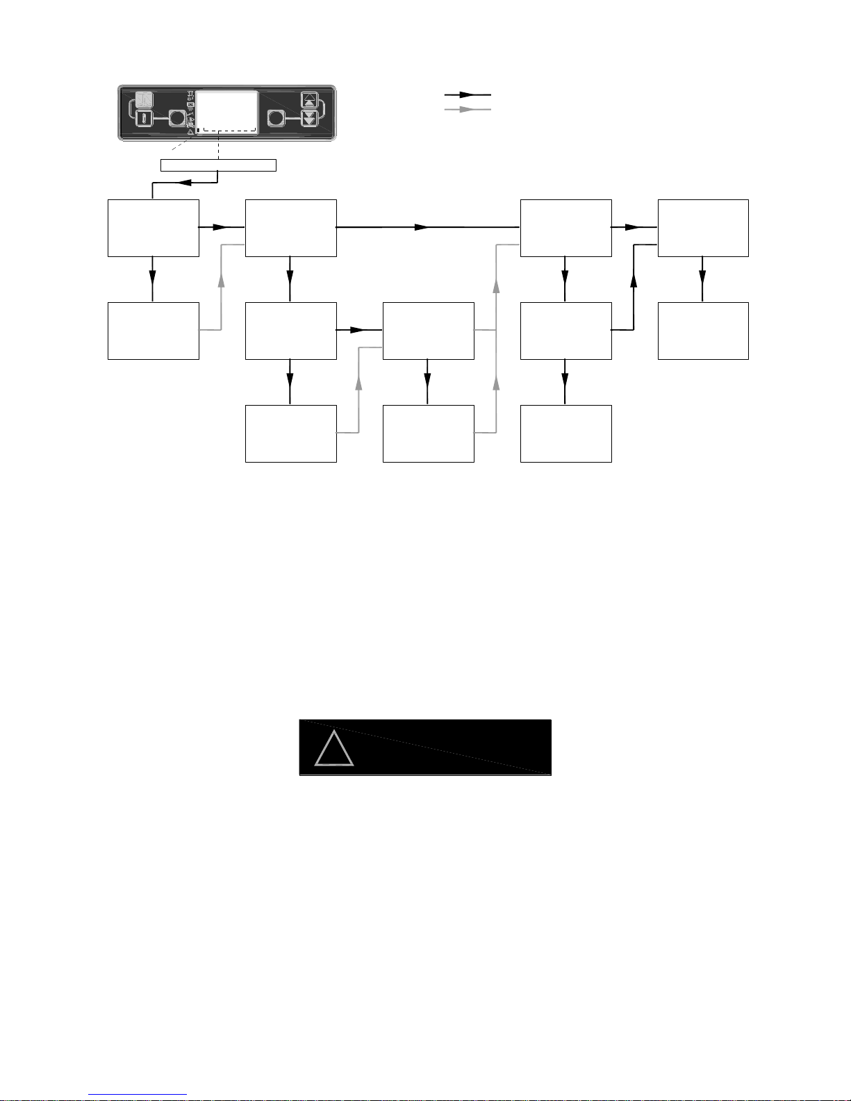
49
11.3.2 SERVO MOTOR BLOCKED
Notes;
1. Refer to section 10.2.3 opening the brazier manually.
2. Refer to section 10.2.5 setting the brazier.
3. Set „T16‟ (time cleaning brazier) to 0, fire-up the boiler immediately switch off the boiler On/Off switch on the
control panel. The brazier cleaning operation will now commence. Ensure „T16‟ is reset to its original
setting or else the brazier operation will be activated after each lighting operation.
4. The stroke of the servo motor is factory set and should not be adjusted. Check with Grant Engineering for
correct setting.
5. The total cleaning time for the brazier should be between 4 and 5 minutes.
Do not to force the brazier end wall
without first disengaging the servo motor release switch.
Failure to release servo motor release switch
will damage servo motor gears.
NO
YES
OPEN BURNER
DOOR, CHECK
BRAZIER FOR
BLOCKAGE
YES
MANUALLY OPEN
BRAZIER,
CHECK IS
BRAZIER SIZED
CLEAR
BLOCKAGE AND
CLOSE BURNER
DOOR
CHECK BRAZIER
CLEARANCE
CORRECT
YES
RESET BRAZIER
CLEARANCE
NO
CHECK BRAZIER
FOR DISTORTION
OR DAMAGE
REPLACE
DAMAGED PARTS
& RESET BRAZIER
CLEARANCE
NO
NO
CHECK SERVO
MOTOR
OPERATION
CORRECT
NO
CHECK SERVO
MOTOR
CONTROLS SET
CORRECT
NO
RESET
CONTROLS
YES
CHECK IS
CLEANING CYCLE
OPERATION TIME
> 5min
YES
REPLACE SERVO
MOTOR
YES
1
2 3
6
54
!
SET
RESET
SET 60°C
H2o 60°C
SERVO MO
Error symbol
SERVO MOTOR BLOCKED
= PRIMARY FAULT
= SECONDARY FOLLOW ON CHECKS
note 1
note 2 note 2
note 4
note 5note 3
WARNING
!
Page 50
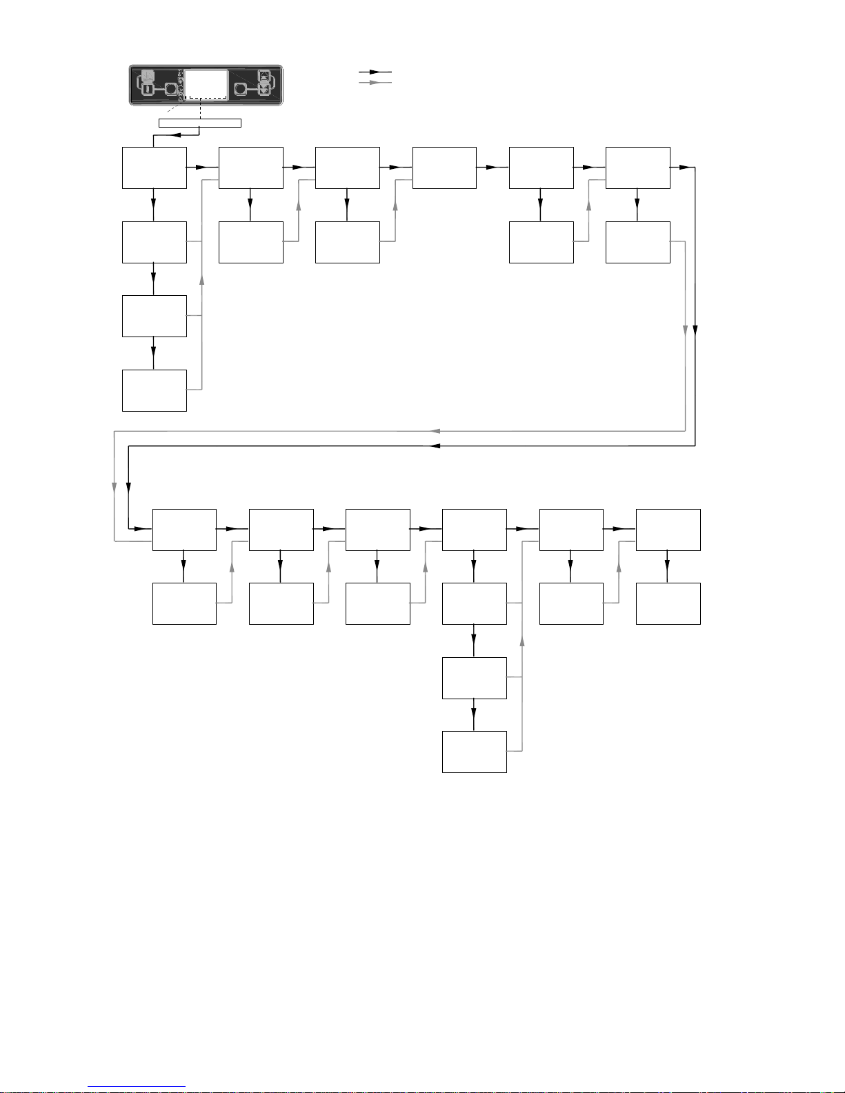
50
11.3.3 SAFETY CHARGE PIPE
Notes;
1. Refer to diagram shown in 9.4.10.
2. Leakage of air could cause increased temperature in the pellet delivery hose and result in the burn-
back thermistor shutting down the burner .
3. Refer to section 9.4.5.
4. Refer to section 6.1.
5. Refer to section 10.3.3
6. Refer to section 8.6. and 8.7.2 p & q
DOES PRESSING
BURNER REST
CANCEL ERROR
(when temp. drops)
NO
DOES REMAKE FEED
PIPE THERMISTOR
CONNECTION &
PRESS RESET
CANCEL ERROR
NO
CHECK FEED
PIPE
THERMISTOR FOR
DAMAGE
REPLACE FEED
PIPE
THERMISTOR
YES
IS COMBUSTION
CHAMBER DRAFT
CORRECT
NO
IS THE CORRECT
FLUE FITTED OR
IS THE FLUE
BLOCKED
IS CONDENSATE
TRAP/PIPE
BLOCKED/ FROZEN
YES
CLEAN
CONDENSATE
TRAP/PIPE
NO
YES
MODIFY FLUE
& OR
CLEAR FLUE
BLOCKAGE
IS THE ASH PAN
OVER-FLOWING
NO
CLEAN OUT ASH
PAN AND BOILER
IS THE WASH
CLEANING SYSTEM
WORKING WHEN
CLEANING TEST
SWITCH ACTIVATED
YES
NO
RESET
'T17' & OR 'T18'
IS CLEANING
SYSTEM
PARAMETERS
'T17' & 'T18' SET
CORRECT
NO
CHECK WATER
MAINS ON
YES
YES
CHECK SOLENOID
OPERATING
CORRECTLY
YES
CHECK JETS
BLOCKED
IN CLEANING
MANIFOLD
CHECK CLEANING
MOTOR
OPERATION
NO
IS ROOM
VENTILATION
ADEQUATE
YES
NO
INCREASE
VENTILATION
1
2 3
6
54
!
SET
RESET
SET 60°C
H2o 60°C
SAFETY CH
Error symbol
SAFETY CHARGE PIPE
Error symbol
YES
note 1
note 1
note 3
note 4
IS THE SHAKER
CLEANING SYSTEM
WORKING WHEN
CLEANING TEST
SWITCH ACTIVATED
note 5
note 5
note 6
= PRIMARY FAULT
= SECONDARY FOLLOW ON CHECKS
NO
YES
IS THE FLUE FAN
OPERATIONAL
NO
YES
RECTIFY FLUE FAN
FAULT / BLOCKAGE
PELLET FEED
TUBE DAMAGED
NO
YES
REPLACE PELLET
FEED TUBE
NO
PELLET FEED
TUBE AIR TIGHT
EACH END
NO
REPLACE PELLET
FEED TUBE
NO
note 2note 2
Page 51
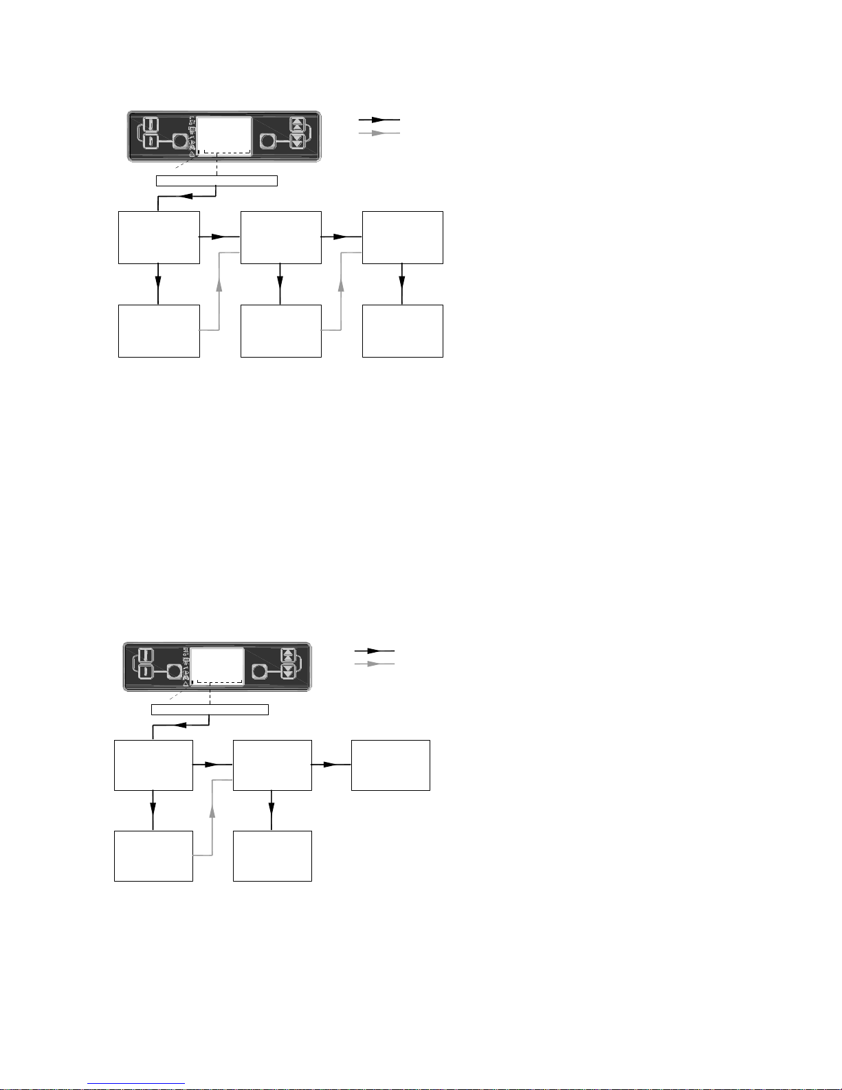
51
11.3.4 SAFETY BOILER THERMOSTAT
Notes;
1. The pocket is located within the boiler control panel. Remove control panel outer cover to gain access.
2. Ensure the heating thermistor is retained in the heating pocket using the clip supplied.
3. Continuity can be checked between T1 & T2 of the seven way male connector plug fitted to the side of the
burner.
4. The boiler comes complete with an air vent to vent the secondary heat-exchanger. The primary heatexchanger needs to be vented on the heating flow pipe. Check flow is adequately vented.
11.3.5 PROBE FAILURE THERMISTOR
Notes;
1. See diagram 9.3.1
11.3.6 AIR PRESSURE ERROR
CHECK HEATING
THERMISTOR
FITTED IN
POCKET
YES
NO NO
YES
REFIT HEATING
THERMISTOR AND
RESET
OVERHEAT
RESET
OVERHEAT STAT
CHECK
CONTINUITY
REPLACE
OVERHEAT
STAT'
IS BOILER
VENTED
CORRECTLY
NO
VENT BOILER
1
2 3
6
54
!
SET
RESET
SET 60°C
H2o 60°C
SAFETY BO
Error symbol
SAFETY BOILER THERMOSTAT (OVERHEAT)
note 1
note 2
note 3
note 4
= PRIMARY FAULT
= SECONDARY FOLLOW ON CHECKS
CHECK BURNER
PLUG
CONNECTIONS
CORRECT
YES
NO
REMAKE
CONNECTION
CHECK HEATING
THERMISTOR FOR
DAMAGE
YES
REPLACE
THERMISTOR
NO
CHECK HEATING
THERMISTOR
CONNECTION ON
BURNER PCB
1
2 3
6
54
!
SET
RESET
SET 60°C
H2o 60°C
PROBE FAI
Error symbol
PROBE FAILURE THERMISTOR
note 1
= PRIMARY FAULT
= SECONDARY FOLLOW ON CHECKS
Page 52
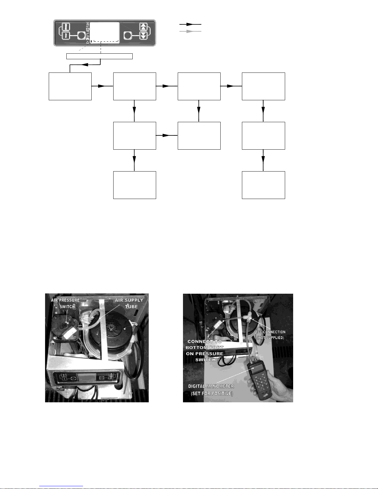
52
Note 1. Before the „PRE-LOAD‟ operation commences and during the LIGHTING FEED REDUCED period, the
burner controls check that burner fan has enough air pressure generated to close the air pressure switch. If during
these operations the pressure switch is not closed then the warning „AIR PRESSURE ERROR‟ is displayed on the
burner screen.
Note 2. During the ‟PELLET BURNER FIRING‟ operation the burner controls checks that the burner fan speed is
correct. (It does not check if the fan is generating enough air pressure). If during the ‟PELLET BURNER FIRING‟
operation the burner fan speed is not correct then the warning „AIR PRESSURE ERROR‟ is displayed on the burner
screen.
Note 3. Check the condition of the air supply tube to the pressure switch, replace if necessary.
Note 4. Using a digital manometer (set for positive pressure) connected as shown below. Check the burner fan is
generating a minimum air pressure of 0.8mbar to activate the air pressure switch.
FIRE BOILER,
CHECK FOR
FAULT DURING
LIGHTING
SEQUENCE
NO
YES
RESET ERROR
MESSAGE BY
PRESSING
'RESET' ON
BURNER DISPLAY
1
2 3
6
54
!
SET
RESET
SET 60°C
H2o 60°C
AIR PRESS
Error symbol
AIR PRESSURE ERROR
= PRIMARY FAULT
= SECONDARY FOLLOW ON CHECKS
YES
CHECK BURNER
FAN IS
OPERATIONAL &
NOT BLOCKED
YES
CHECK PRESSURE
SWITCH
OPERATION &
CONDITION OF AIR
SUPPLY TUBE
CHECK BURNER
FAN IS
OPERATIONAL &
NOT BLOCKED
NO
CLEAR
BLOCKAGE
AND/OR REPLACE
FAN
NO
CHECK BURNER
FAN PRESSURE IS
CORRECT
NO
REPLACE
BURNER FAN
-CORRECT FAN
PRESSURE
ACHIEVED
NO
REPLACE MAIN
BURNER PCB
note 1
note 3
note 2
note 4
Page 53
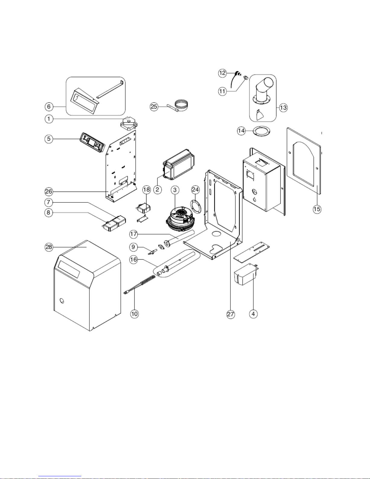
53
12 Spare parts
12.1 Burner
Burner controls –Exploded view
Fig 12.1
Page 54
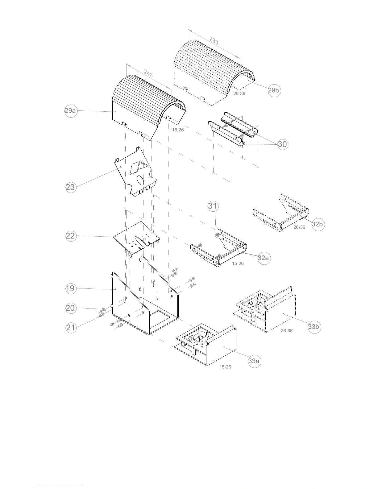
54
Burner Brazier –Exploded view
Fig 12.2
Page 55

55
Burner parts list
Item
Description
Part No.
Quantity
Quantity
6-26
9-36
1
Pressure switch
WP111 1 1
2
Primary printed circuit board c/w enclosure
WP112 1 1
3
Burner fan
WP03 1 1
4
Servomotor
WP04 1 1
5
LED display unit c/w enclosure
WP05 1 1
6
Mounting bracket set (LED display)
WP06 1 1
7
Electrical connector 7 way female
WP07 1 1
8
Electrical connector 7 way male
WP08 1 1
9
Photocell
WP09 1 1
10
Ignition element
WP10 1 1
11
Pellet feed tube thermistor
WP11 1 1
12
Pellet feed tube thermistor cover
WP12 1 1
13
Pellet feed tube
WP13 1 1
14
Pellet feed tube gasket
WP14 1 1
15
Burner mounting gasket
WP15 1 1
16
Ignition element housing
WP16 1 1
17
Photocell tube
WP17 1 1
18
Electrical connector 6 way male
WP18 1 1
19
Brazier chassis
WP19 1 1
20
M6 washer
WP20 8 8
21
M6 nut
WP21 8 8
22
Ignition element mounting plate
WP22 1 1
23
Photocell back plate
WP23 1 1
24
Burner fan gasket
WP24 1 1
25
Boiler water thermistor
WP25 1 1
26
Controls chassis left gable
WP26 1 1
27
Controls chassis back-plate & base
WP27 1 1
28
Main burner cover
WP28 1 1
29a
Flame hood 6-26
WP29A 1 -
29b
Flame hood 9-36
WP29B - 1
30
Brazier flame plate set
WP130 1 1
31
M6 x 15 Coach bolt
WP31 8 8
32a
Grate enclosure (6-26)
WP32A 1 -
32b
Grate enclosure (26-26)
WP32B - 1
33a
Brazier base assembly 6-26
WP33A 1 -
33b
Brazier base assembly 9-36
WP33B - 1
Page 56
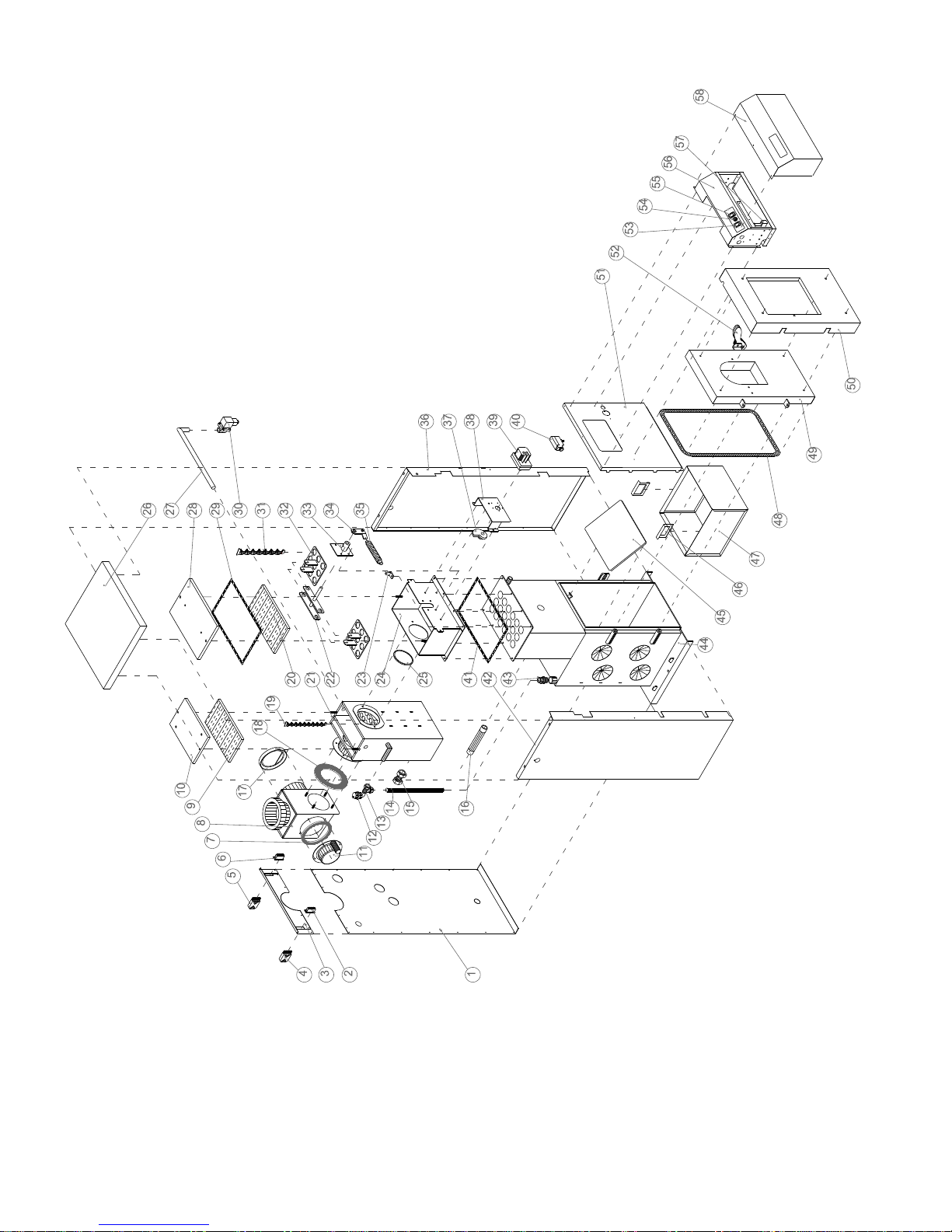
56
12.2 Boiler Exploded view
Fig 12.3 SPIRA 6-26 boiler displayed
Boiler parts list
Page 57

57
Item
Description
Part No.
Quantity
Quantity
6-26
9-36
1
Rear lower panel
WP34 1 1
2
5 way mains connection –male fixed
WP 35 1 1
3
Rear upper panel
WP36 1 1
4
5 way mains connection –female detachable
WP37 1 1
5
5 way flue fan / cleaning solenoid connection –male detachable
WP38 1 1
6
5 way flue fan /cleaning solenoid connection – female fixed
WP39 1 1
7
Flue fan sealing gasket
WP40 1 1
8
Fan box
WP41 1 1
9
Cleaning door sealing gasket –secondary 6-26
WP42 1 -
-
Cleaning door sealing gasket –secondary 26-26
WP43 - 1
10
Cleaning door –secondary 6-26
WP44 1 -
-
Cleaning door –secondary 26-26
WP145 - 1
11
Flue fan
WP46 1 1
12
Air vent
MPCBS29 1 1
13
Air vent manifold
WP48 1 1
14
22mm Secondary to primary pipe 6-26
WP49 1 -
-
22mm Secondary to primary pipe 9-36
WP50 - 1
15
Return assembly 6-26
WP51 1 -
-
Return assembly 9-36
WP52 - 1
16
1” BSP Flow pipe 6-26
WP53 1 -
-
1 ¼” BSP Flow pipe 9-36
WP54 - 1
17
Draught Stabilizer
WP55 1 1
18
Fan box/secondary gasket
WP56 1 1
19
Secondary heat-exchanger spiral baffle
WP57
30
40
20
Cleaning door sealing gasket –Primary 6-26
WP58 1 -
-
Cleaning door sealing gasket –Primary 9-36
WP59 - 1
21
Secondary heat-exchanger 6-26
WP60 1 -
Secondary heat-exchanger 9-36
WP61 - 1
22
Shaker arm assembly 6-26
WP62 1 -
-
Shaker arm assembly 9-36
WP63 - 1
23
Spring anchor -fixed
WP64 1 1
24
Shaker chamber 6-26
WP65 1 -
-
Shaker chamber 9-36
WP66 - 1
25
Primary/secondary gasket
WP67 1 1
26
Top panel 6-26
WP68 1 -
-
Top panel 9-36
WP69 - 1
27
Cleaning pipe manifold 6-26
WP70 1 -
-
Cleaning pipe manifold 9-36
WP71 - 1
28
Cleaning door-shaker chamber 6-26
WP72 1 -
-
Cleaning door-shaker chamber 9-36
WP73 - 1
29
Fibre rope -shaker chamber door 6-26
WP74 1 -
-
Fibre rope -shaker chamber door 9-36
WP75 - 1
30
Solenoid valve
WP76 1 1
31
Secondary heat-exchanger spiral baffle
WP77
18
24
32
Spiral hanger 6-26
WP78 1 -
-
Spiral hanger 9-36
WP79 - 1
33
Shaker assembly mounting flange
WP80 1 1
34
Spring anchor -movable
WP81 1 1
35
Cleaning mechanism spring
WP82 1 1
36
Right side panel 6-26
WP83 1 -
-
Right side panel 9-36
WP84 - 1
37
Cleaning mechanism cam
WP85 1 1
38
Cleaning motor mounting flange
WP86 1 1
39
Cleaning mechanism motor
WP87 1 1
40
Door interlock
WP88 1 1
41
Shaker chamber mounting gasket 6-26
WP89 1 -
-
Shaker chamber mounting gasket 9-36
WP90 - 1
42
Left side panel 6-26
WP91 1 -
-
Left side panel 9-36
WP92 - 1
43
Brass fitting 1”BSP x 22mm 311
WP93 1 -
-
Brass fitting 1 1/4”BSP x 28mm 311
WP94 - 1
44
Primary heat-exchanger 6-26
WP95 1 -
-
Primary heat-exchanger 9-36
WP96 - 1
45
Combustion chamber baffle 6-26
WP97 1 -
-
Combustion chamber baffle 9-36
WP98 - 1
46
Ash pan handles
WP99 2 2
47
Ash pan 6-26
WP100 1 -
-
Ash pan 9-36
WP101 - 1
48
Combustion chamber cleaning door rope
WP102 1 1
49
Combustion chamber cleaning door
WP103 1 1
50
Combustion chamber cleaning door panel
WP104 1 1
51
Front panel
WP105 1 1
52
Combustion chamber cleaning door handle
WP106 1 1
53
On/Off switch
EFBS22 1 1
54
Limit stat‟
WP107 1 1
55
Momentary switch (double pole on/on)
WP108 1 1
56
Control panel chassis
WP109 1 1
57
Relay
MPCBS72X 1 1
58
Control panel cover
WP110 1 1
59
Plug (not show)
60
Plug (not shown)
Items not indexed are specific to the 9-36 model.
12.3 Intermediate Hopper -Exploded view (rear)
Page 58
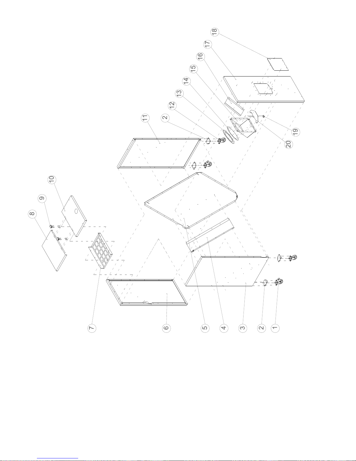
58
Fig. 12.4
.
Intermediate Hopper parts list
Page 59

59
Item
Description
Part No.
Quantity
6-26 & 9-36
1
Castor Wheel (c/w brake)
WP146
2
2
Caster wheel flange
WP147
4
3
Right side panel
WP148
1
4
Pellet feed Auger shield
WP149
1
5
Base
WP150
1
6
Front panel
WP151
1
7
Grid
WP152
1
8
Top front panel
WP153
1
9
Door hinge
WP154
2
10
Top rear panel
WP155
1
11
Left side panel
WP156
1
12
Castor Wheel
WP157
2
13
Rubber diaphragm flange
WP158
1
14
Rubber diaphragm
WP159
1
15
Wiring centre
WP160
1
16
Pellet damper
WP161
1
17
Rear panel
WP162
1
18
Wiring centre access cover
WP163
1
19
Low level limit switch
WP164
1
20
Limit switch bracket
WP165
1
Page 60

60
13. Health and Safety Information
Under the Consumer Protection Act 1987 and section
6 of the Health & safety at Work Act 1974, we are
required to provide information on substances
hazardous to health (COSHH Regulations 1988).
Adhesives, sealants and paints used in the
manufacture of the product are cured and present no
known hazards when used in the manner for which
they are intended.
The following other materials are present in the
product;
13.1 Insulation Materials
Material types; Ceramic fibre board, mineral wool.
Description; Rigid board, slabs, sleeves, gaskets,
ropes.
Known Hazards: May cause temporary irritation or
rash to skin. High dust levels may irritate eyes and
upper respiratory system.
Precautions; Avoid unnecessary or rough handling,
or harsh abrasion of boards. Normal handling and use
of material should not produce high dust levels.
Avoid inhalation and contact with skin and eyes.
After handling always follow normal good hygiene
practices.
Protection; Use disposable gloves, face mask and
eye protection.
First Aid. Eyes – If irritation occurs, wash eyes with
copious amounts of water. If symptoms persist, seek
immediate medical advice.
Skin – If irritation occurs, wash under running water
before washing with soap and water.
Inhalation –Remove to fresh air, drink water to clear
throat and blow nose to remove dust/fibres.
Ingestion –Drink plenty of water.
13.2 Sealant and adhesive
Material Types; Silicone elastomer.
Description; Sealant and adhesive.
Known Hazards: Irritation to eyes.
Precautions; Avoid inhalation of vapour, contact with
eyes and prolonged or repeated contact with skin.
After handling always follow normal good hygiene
practices.
Protection: Use eye protection. Rubber or plastic
gloves should be worn where repeated contact occurs
and a face mask worn when working in confined
spaces.
First Aid; Eyes –Flush eyes with water for 15
minutes. See immediate medical attention.
Skin –Wipe off and wash with soap and water.
Inhalation –Remove to fresh air.
Page 61

61
14. Warranty
1. The company shall mean Grant Engineering (Ireland) Limited.
2. The boiler is guaranteed for a period of 12 months from the date of purchase, providing that;
a. The boiler is commissioned & installed by an engineer who has completed the Grant Wood pellet training
course on wood pellet boilers and is an SEAI registered installer.
b. Any work undertaken is authorised by the Company and carried out by an approved service agent.
c. The boiler is run on approve 6mm wood pellets as described in section 2.3 & section 3 of this manual.
3. The primary and secondary heat-exchangers of the wood pellet boiler manufactured by Grant Engineering (Ireland)
Limited are guaranteed for a period of 5 years from the date of installation. All other components except consumables
are guaranteed for a period of 1 year.
4. The guarantee starts from the date of purchase.
5.The guarantee does not cover breakdowns caused by incorrect installation, neglect, misuse, accident or failure to
operate this boiler in accordance with the manufacturer‟s instructions.
6. This guarantee is non transferable unless sanctioned by the company.
7. The company will endeavour to provide prompt service in the unlikely event of a problem occurring, but cannot be
held responsible for any consequence of delay however caused.
8. This guarantee does not cover labour handling or shipping.
9. This guarantee applies to boilers installed on the island of Ireland both North and South. Provision for warranty
cover elsewhere is subject to agreement with Grant Engineering (Ireland) Limited.
10. All claims under this guarantee must be made and agreed with by Grant Engineering (Ireland) Ltd. prior to any
work being carried out. Proof of purchase and date of installation must be provided on request. Invoices for call
out/repair work carried out by any third party will not be acceptable unless previously authorised by the company.
11. Grant Engineering do not accept any responsibility for damage, how so ever caused, to plastic piping or fittings
used on the heating system.
Page 62

62
15. Notes
_________________________________________________________________________
_________________________________________________________________________
_________________________________________________________________________
_________________________________________________________________________
_________________________________________________________________________
_________________________________________________________________________
_________________________________________________________________________
_________________________________________________________________________
_________________________________________________________________________
_________________________________________________________________________
_________________________________________________________________________
_________________________________________________________________________
_________________________________________________________________________
_________________________________________________________________________
_________________________________________________________________________
_________________________________________________________________________
_________________________________________________________________________
_________________________________________________________________________
_________________________________________________________________________
_________________________________________________________________________
_________________________________________________________________________
_________________________________________________________________________
_________________________________________________________________________
_________________________________________________________________________
_________________________________________________________________________
_________________________________________________________________________
Page 63
63
EC Declaration of Conformity
We Grant Engineering (Ireland) Limited under our sole responsibility declare that the Grant
Spira Wood pellet boiler as listed below complies with the requirements of the
The Low Voltage Directive (LVD) 2006/95/EC
Standard used; EN60335-1 2002
The Electromagnetic Compatibility Directive 2004/108/EC
Standard used; EN 55014 -1: 2007
Product Category; Floor Standing Domestic Condensing Wood pellet boiler
Model; Grant Spira 6-26 Wood Pellet Boiler
Grant Spira 9-36 Wood Pellet Boiler
 Loading...