

Grant Spira Series, Spira 6-26, Spira 9-36, Spira 18-72, Spira 12-52 Installation & Servicing Instructions Manual
...
Grant Spira 6-26 kW and 9-36 kW
Condensing Wood Pellet Boiler
Installation & Servicing Instructions
Part No. DOC 42 Rev 01. May 2013
PROVISIONAL COPY

Important Note
2
Important Note
Important Note for Installers
After installing the boiler leave these
instructions with the Appliance.
Leave the user manual with the
householder.
This appliance is deemed a controlled
service and specific regional statutory
requirements may be applicable.
GRANT ENGINEERING (UK) LIMITED
Hopton House, Hopton Industrial Estate, Devizes, Wiltshire SN10 2EU
Tel: 01380 736920 Fax: 01380 736991
Email: sales@grantuk.com www.grantuk.com
This manual is accurate at the date of printing but will be superseded and should be disregarded if specifications and/or
appearances are changed in the interests of continued product improvement.
All good sold are subject to our official Conditions of Sale, a copy of which may be obtained on application.
© Grant Engineering (UK) Limited 2013. No part of this manual may be reproduced by any means without prior written consent.

Contents
3
Contents
1 Introduction 4
1.1 How the Condensing
Wood Pellet Boiler Operates 5
1.2 Boiler Description 5
1.3 Boiler Models 5
1.4 Boiler Components 6
1.5 Boiler Cleaning and Servicing 7
2 Technical data 8
2.1 Boiler & Hopper
Technical Data 8
2.2 Boiler Input and
Output Data 9
2.3 Flue Gas Analysis 9
2.4 Boiler and Hopper
Dimensions and Clearances 10
3 Pellet Specification
& Storage 13
3.1 Pellet Specification 13
3.2 Pellet Storage 14
4 Installation information 16
4.1 Introduction 16
4.2 Boiler Location 16
4.3 Preparation for Installation 16
4.4 Installing the Boiler 16
4.5 Regulations 16
4.6 Heating System Design
Considerations 16
4.7 Pipework Materials 16
4.8 Pipe Connections 17
4.9 Wash System Manifold 17
4.10 Fan Box and Flue Starter 17
4.11 Pellet Hoppers 18
4.12 Pellet Feed Auger 18
4.13 Before you Commission 19
4.14 Completion 19
5 Condensate disposal 20
5.1 General Requirements 20
5.2 Connections 20
5.3 Pipework 20
5.4 External Pipework 20
5.5 Condensate Soakaway 20
5.6 Condensate Trap 21
5.7 Inspection and Cleaning
of Trap 21
6 Sealed Systems 22
6.1 Sealed System
Requirements 22
6.2 Filling the Sealed System 22
6.3 Venting the Pump 23
6.4 Pressure Relief (Safety)
Valve Operation 23
7 Flue System and
Air Supply 24
7.1 Air Supply 24
7.2 Flue Position and
Clearances 24
7.3 Flue System Assembly 25
7.4 Flue Notice Plate 27
7.5 Carbon Monoxide Alarm 27
7.6 Flue System Components 28
7.7 Flue Component
Dimensions 30
7.8 Typical Flue Systems 31
8 Electrical 32
8.1 General Requirements 32
8.2 Hopper Electrical
Connections 32
8.3 Boiler Plug Connections 32
8.4 Heating System Controls 33
8.5 Connecting the Power
Supply 33
8.6 Wiring Diagrams 34
9 Burner 40
9.1 Burner Operation 40
9.2 Burner Operational Modes 40
9.3 Burner Operational
Sequence 41
9.4 Burner Display Screen 42
9.5 Burner Control Buttons 42
9.6 Burner Menu Navigation
Chart and Factory Default
Setting 43
9.7 Burner Menu 44
10 Commissioning 47
10.1 Equipment Required 47
10.2 Preliminary Inspection 47
10.3 Boiler 47
10.4 Pellet Hopper 48
10.5 Safety Device Checks 48
10.6 Burner Setting 49
10.7 Priming the Pellet Feed
Auger 49
10.8 Lighting the Boiler 50
10.9 Combustion Chamber
Draught 50
10.10 Flue Gas Analysis 51
10.11 Customer Handover 51
10.12 Commissioning Report
Form 52
10.13 Commissioning Check List 52
11 Boiler Servicing 53
11.1 General 53
11.2 Checks Before Servicing 53
11.3 Heating System 53
11.4 Flue System 53
11.5 Combustion Ventilation 54
11.6 Boiler 54
11.7 Burner Brazier 56
11.8 Burner Components 57
11.9 Re-fitting Burner 58
11.10 Condensate Disposal
System 58
11.11 Burner Settings 58
11.12 Safety Device Checks 59
11.13 Combustion Checks 59
12 Fault Finding 60
12.1 General 60
12.2 Normal Screen Display 61
12.3 No Screen Display 62
12.4 Boiler Overheat Thermostat 64
12.5 Pellet Tube Thermostat 65
12.6 Failed Pellet Lighting 67
12.7 Servo Motor Blocked 69
12.8 Probe Failure Thermostat 70
12.9 Air Pressure Error 71
13 Spare Parts 72
14 Health & Safety
Information 80
15 EC Declaration of
Conformity 81
16 Warranty 82

Introduction
4
1 Introduction
Grant SPIRA Condensing Wood Pellet Boiler & Intermediate Hopper
Intermediate Hopper
Wood Pellet Boiler
Boiler Controls
Pellet Feed Auger
Pellet Delivery Hose
Pellet Delivery Tube
Burner Controls
Wood Pellet Burner
This manual is intended to guide
Installers who have completed the
Grant Wood Pellet Boiler Installer
training course on the installation,
commissioning and servicing of the
Grant SPIRA Condensing Wood Pellet
Boiler.
A separate manual is available to guide
users in the operation of the boiler.
The following special text formats are
used in this manual for the purposes
listed:
Warning of possible human injury as
a consequence of not following the
instructions in the “warning”.
Caution concerning likely damage to
equipment or tools as a consequence
of not following the instructions in
the “Caution”.
Note text: Used for emphasis or
information not directly concerned
with the surrounding text but of
importance to the reader.
!
WARNING
!
CAUTION
!
NOTE

Introduction
5
1.1 How the Condensing
Wood Pellet Boiler Operates
During the combustion process,
hydrogen and oxygen combine to
produce heat and water vapour. The
water vapour produced is in the form of
superheated steam in the heat
exchanger. This superheated steam
contains sensible heat (available heat)
and latent (heat locked up in the flue
gas). A conventional boiler cannot
recover any of the latent heat and this
energy is lost to the atmosphere
through the flue.
The Grant SPIRA Condensing wood
pellet boiler contains an extra
(secondary) heat exchanger which is
designed to recover the latent heat
normally lost by a conventional boiler. It
does this by cooling the flue gases to
below 90°C thus extracting more
sensible heat and some of the latent
heat. This is achieved by cooling the
flue gases to their dew point.
The boiler has been independently
tested to BS EN303-5 and will achieve
the following full load efficiencies when
both the boiler and system are correctly
set:
To ensure maximum efficiency from the
Grant SPIRA boiler, the boiler return
temperature should be 55°C or less
(but NOT less than 40°C) at
maximum operating temperature.
This will enable the latent heat to be
condensed out of the flue gases.
The boiler is capable of a maximum
flow temperature of 75°C.
To achieve the required return
temperature (55°C or less), it is
recommended that the heating system
is designed and balanced to operate
with a temperature differential of 20°C
between flow and return. The use of
modulating circulating pumps (now
widely available) and effective control
systems should be considered.
Grant SPIRA condensing wood pellet
boilers will still operate at extremely
high efficiencies even when not in
condensing mode and are therefore
suitable for fitting to an existing heating
system without alteration to the radiator
sizes.
1.2 Boiler Description
The Grant SPIRA boiler uses a drop
feed type burner with modulated heat
output. The burner output is
determined by varying the feed and
pause time of the pellet feed auger
supplying pellets to the burner. See
Section 8 for details of burner operation.
The boiler is suitable for use on a
sealed or open vented central heating
system. When commissioned and set
correctly, Grant SPIRA condensing
wood pellet boilers will operate
automatically, using a typical heating
control system.
All models are supplied with the control
panel and burner factory fitted. The
combined fan box & flue starter, pellet
feed auger and hopper are supplied
separately and are fitted by the installer.
See Section 4 for boiler installation.
The boiler needs to be connected to a
conventional flue system. There is no
provision for connection to a balanced
flue system as there is draft stabilizer
fitted to the appliance.
The boiler is not designed specifically
for operation on a system with a buffer
tank/ thermal store, however when
used on such a system there is no
effect on the boiler performance.
!
NOTE
Model Nominal Reduced
Output Output
SPIRA 6-26 97.4% 96.4%
SPIRA 9-36 93.1% 98.1%
The only flue suitable for use with
the Grant SPIRA condensing wood
pellet boiler is the Grant ‘Black’
twin-wall insulated conventional flue
system. This 125mm (5”) diameter,
black powder coated stainless steel
flue system is suitable for both
6-26kW and 9-36kW Spira models.
For the 52kW, 62kW and 72kW
double boiler installations each
boiler must have a separate flue
system. Refer to Section 7.
Product
Code Model Description
WPS626RH110 6-26 1 x 6-26kW boiler + 110kg right hand hopper
WPS626LH110 6-26 1 x 6-26kW boiler + 110kg left hand hopper
WPS626RH200 6-26 1 x 6-26kW boiler + 200kg right hand hopper
WPS626LH200 6-26 1 x 6-26kW boiler + 200kg left hand hopper
WPS936RH110 9-36 1 x 9-36kW boiler + 110kg right hand hopper
WPS936LH110 9-36 1 x 9-36kW boiler + 110kg left hand hopper
WPS936RH200 9-36 1 x 9-36kW boiler + 200kg right hand hopper
WPS936LH200 9-36 1 x 9-36kW boiler + 200kg left hand hopper
WPS1252 12-52 2 x 6-26kW boilers + 140kg double boiler hopper
WPS1562 15-62 1 x 6-26kW boiler and 1 x 9-36kW boiler
+ 140kg double boiler hopper
WPS1872 18-72 2 x 9-36kW boilers + 140kg double boiler hopper
1.3 Boiler Models
The Grant SPIRA condensing wood
pellet boiler is available in eleven
different models:

Introduction
6
1 Introduction
1.4 Boiler Components
1.4.1 Burner. The burner is supplied
factory-fitted to the boiler. All burners
are supplied with factory default
settings. During commissioning each
burner parameter will need to be
checked (see Section 8), and adjusted
if necessary as the flue length can have
a significant effect on the boiler
performance. Refer to commissioning in
Section 9.
The Burner is equipped with a self
cleaning device to prevent a build up of
ash and clinker in the burner brazier.
The burner output is determined by the
feed / pause times of the pellet feed
auger supplying the burner. See Section
8 for full burner operation details.
1.4.2 Boiler. The SPIRA condensing
boiler is supplied with a combined
primary and secondary heat-exchanger.
Both heat exchangers are equipped
with a self cleaning system.
1.4.3 Boiler controls. The set-point
temperature of the boiler is user
adjustable via two push buttons on the
burner control panel - see Section 8.4
for details.
The boiler control panel (See Figure 1.1.)
is located at the top of the boiler and is
fitted with three controls, as follows:
ON/STAND-BY switch – to switch off
the burner when required, by
interrupting the switched live supply to
the burner. This switch does not isolate
the electrical supply to the burner.
OVERHEAT thermostat - this allows
the boiler to be used on a sealed
central heating system and will
automatically switch off the boiler if the
pre-set temperature of 110°C is
exceeded.
CLEANING switch - when pressed
and held in the TEST position, it allows
the cleaning system to be manually
operated and tested. When released it
will automatically return to the default
AUTO position to allow the boiler
cleaning system to perform
automatically. Only operate the cleaning
switch when the boiler is in ‘WAIT
BOILER THERMOSTAT’.
1.4.4 Boiler Pellet Hoppers. All single
boilers (Spira 6-26 and 9-26 models)
come with a pellet hopper. Two sizes of
hopper are available for use with single
boilers, as follows:
• 110 kg hopper – for storing a
maximum of 110kg
(≈170 litres) of wood pellets
• 200kg hopper – for storing a
maximum of 200kg
(≈308 Litres) of wood pellets.
There are two versions of both the
110kg and 200kg pellet hopper
available for use with a single boiler:
Left hand hopper – to be positioned
on the left hand side of the boiler. This
is the ‘standard’ option and will be
automatically supplied with the boiler
unless specified otherwise.
Right hand hopper – to be positioned
on the right hand side of the boiler. This
is the ‘non-standard’ option and must
be specified when ordering the boiler.
Both hoppers are supplied with a single
1.2m pellet feed auger, to be fitted to
the hopper on site by the installer.
All ‘double boiler’ installations (Spira
12-52, 15-62 and 18-72 models) come
with one 'double' hopper to feed both
boilers. This hopper is positioned
between the two boilers and stores a
maximum of 140 kg (≈215 litres).
ALL the Grant pellet hoppers are for
indoor use only and must be
positioned in a dry environment.
Hopper contents switch
All hoppers are fitted with a contents
switch. This detects when the level of
pellets in the hopper falls to a pre-set
minimum value and triggers the
operation of either a bulk store auger,
or vacuum system, to delivery pellets
from the bulk pellet store.
If no bulk store is used, the contents
switch will stop the burner operating
when the minimum pellet level is
reached.
Topping up the hopper with more
pellets will automatically operate the
contents switch and the burner will
restart (if there is a demand for the
boiler to run).
The minimum quantity of pellets
required to restart the boiler is 20kg for
the single boiler hoppers and 3kg for
the double boiler hoppers.
All boiler pellet hoppers are for
indoor use only and MUST be
positioned in a dry environment free
from dampness. They must be located
on the same floor level as the boiler, or
boilers, they are supplying.
All hoppers are mounted on four
castors (with the two front castors
lockable) to allow it to be easily moved
when required. Allow sufficient area in
front of the hopper for it to be moved
out and away from the boiler(s) during
servicing.
The electrical connections to the
boiler(s) are all made to the 4-way
electrical plug on one of the three
factory-fitted ‘flying leads’ at the rear of
the hopper. Refer to Section 7 for
details.
After the burner has been switched
off (either manually by the switch on
the control panel, or automatically by
the boiler control stat, or the heating
system controls) the burner needs to
burn-down the remaining pellets in
the brazier. Do not open the front
combustion chamber access door
until the burner display reads “WAIT
BOILER THERMOSTAT”.
!
WARNING
Figure 1-1: Boiler control panel

Introduction
7
All hoppers are supplied with a
rectangular blanking plate fitted on the
top rear panel. This can be removed, as
required, to allow the fitting of the Grant
SPIRA-VAC pellet feed system. Refer to
Installation Instructions supplied with
the Grant SPIRA-VAC system for further
details.
This blanking plate has a single round
‘knock-out’ to provide an entry into the
hopper from an auger supplying pellets
from a bulk hopper system. This
knockout is positioned to ensure the
pellets drop into the hopper and
operate the hopper contents switch.
Only this opening MUST be used as
making another opening in the
intermediate hopper could affect the
operation of the contents switch.
Electrical connection for either a bulk
auger or Grant SPIRA-VAC system, if
required, is made using the 6-way
electrical plug and flying lead supplied
factory-fitted at the rear of the hopper.
Refer to Section 7 for connection
details.
Always ensure that the door and top
panel of the boiler hopper are fitted to
ensure no foreign debris enters the
hopper. If a bulk system with an auger
is fitted, ensure that the bulk auger
does not impede the opening of the
hopper door.
1.4.5 Pellet Feed Auger. All Grant
hoppers are supplied with either one or,
on double boiler hoppers, two 1.2m
pellet feed augers. These are set at a
fixed angle of 45° to maintain a
consistent feed. If the pellet feed auger
angle is altered the input to the boiler
will also be altered.
The pellet feed auger is a hollow spiral
type. Its function is to deliver the pellets
from the hopper to the burner. The
output of the boiler is determined by
varying the on/off periods of the pellet
feed auger motor. Refer to Section 2.2
for pellet feed data.
1.5 Boiler Cleaning and
Servicing
Grant SPIRA condensing wood pellet
boilers are equipped with an automatic
cleaning system for each of the two
heat exchangers and also for the
burner brazier.
Care must be taken to avoid contact
with hot surfaces.
Always wait for the boiler to cool
down before opening the
combustion chamber door and
removing the ash pan.
The boiler MUST be serviced either
ANNUALLY or when a service is
indicated on the burner control panel
display, whichever comes first.
Servicing should only be carried out
by a Grant Approved Installer and
details of each service should be
recorded in the Service Log in the
back of the User Operating Manual.
!
WARNING
The ash pan (located inside the
combustion chamber) will need to be
periodically emptied. This simple
task must be carried out by the user
at MONTHLY intervals for the FIRST
THREE MONTHS. Thereafter, the ash
pan should be emptied regularly, on
at least a monthly basis, or as
indicated by the amount of ash
found during the first three months.
Two carrying handles are supplied
with the boiler to allow removal of
the ash pan when hot.
!
CAUTION
The amount of ash produced varies
between the different pellet brands
and this will affect the frequency of
cleaning and maintenance required.
!
NOTE

Technical Data
8
2 Technical Data
2.1 Boiler & Hopper Technical Data
Spira Model
Model Number Units 6-26 9-36
Maximum heat Output kW 26 36
Btu/hr 88,700 122,800
Flow connection - 1" BSP (Female) 1 1/4" BSP (Female)
Return connection - 1" BSP (Female) 1 1/4" BSP (Female)
Water content Litres 51.5 60
Waterside resistance ΔT = 10°C mbar 26.0
Waterside resistance ΔT = 20°C mbar 9.5
Mains water (cleaning system) bar 1 bar operating pressure
Condensate connection - 11/4" BSP (Female)
Conventional flue - 125mm (5") Black system
Combustion chamber draught requirement mbar 0.10 to 0.15 (running)
Maximum static head m 25
Minimum circulating head m 1
Boiler temperature set point range °C 55° to 75°C
Boiler temperature cut out point °C 65° to 80°C
Minimum return temperature °C 40°C
Water system overheat cut-out temp. °C 110°C
Burn-back overheat thermostat cut-out °C 60°C
Electricity supply - 230V~50Hz
Max operating pressure - sealed system bar 2.5 bar
Max operating pressure - open system bar 2.5 bar
Maximum auger length (bulk hopper) metres 6.0
Maximum auger speed (bulk hopper) rpm 30
Minimum flue length m 2.0
Maximum flue length m 12.0
Heating element rating Watts 450
Intermediate auger motor power Watts 55
Intermediate auger motor starting current Amps 0.64
Intermediate auger motor running current Amps 0.64
Intermediate auger speed rpm 8.1
Flue fan motor power Watts 32
Flue fan motor starting current Amps 0.27
Flue fan motor running current Amps 0.13
Cleaning solenoid power Watts 10
Cleaning solenoid current Amps 0.087
Burner fan motor power Watts 56
Total burner start current amp 2.5
Total burner run current amp 0.60

Model MAX Flame MIN Flame
Pellet Burner setting Heat Heat Draught CO2Burner Heat
feed Output Input Setting Output
Auger TIME TIME kW kW Full Input mbar % TIME kW
angle LOAD PAUSE (Btu/h) (Btu/h) Eff. kg/hr* (in.wg) PAUSE (Btu/h)
MAX MIN
SPIRA 45° 0025 0025 26.3 27.1 97.4 5.70 0.1–0.15 10–12 0140 6.5
6-26 (2.5sec) (2.5sec) (89,735) (92,500) (0.04-0.06) (14.0sec)) (22,100)
SPIRA 45° 0065 0025 36 38.7 93.1 7.78 0.1–0.15 10–12 0250 9
9-36 (6.5sec) (2.5 sec) (122,832) (132,000) (0.04-0.06 (25sec) (30,700)
in.wg)
1. *Heat input is based on a calorific value of 4.81 kWh/kg.
2. Heat input and output data given above is approximate only.
Technical Data
9
2.2 Boiler Input and Output
Data
The settings in the table below are
based on the boiler using the Grant
fixed angle pellet feed auger at 45° with
an auger motor fixed speed of 8.1 rpm.
Only ENplus A1 (EN14961-2) pellets
MUST be used with the Grant SPIRA
boilers. These pellets must be bark
and sand free AND approved by
Grant UK BEFORE being used in the
Spira boilers. Failure to use approved
pellets will invalidate the product
warranty.
2.2.1 Burner settings
All burner settings must be checked as
part of commissioning and servicing.
Refer to Section 9.6 for full details of
the burner settings and how to access,
check and, where necessary, how to
adjust them.
Boiler and Hopper Weights
2.3 Flue Gas Analysis
As part of both the commissioning and
servicing procedures, the CO
2
content
of the flue gases must be checked. To
enable this to be done, the boiler is
supplied with a combustion test point in
the top rear cleaning door. Refer to
Figure 10-17.
To gain access to this test point, first
remove the top casing panel from the
boiler. The test point should be at the
back left corner of the rear cleaning
door. If it is located at the front right
corner of the cleaning door, then
remove the door and refit it with the
test point in the correct position.
Spira Model
Model Number Units 6-26 9-36
Weight boiler – less burner and fan box (empty) kg 201 231
Weight burner kg 25.5 25.5
Weight fan box kg 5 5
Total weight of boiler (empty) kg 231.5 261.5
Total weight of boiler (full) kg 283 321.5
Weight 110kg pellet hopper (empty) – incl. auger kg 41.35 41.35
Weight 110kg pellet hopper (full) – incl. auger kg 151.35 151.35
Weight 200kg pellet hopper (empty) – incl. auger kg 77 77
Weight 200kg pellet hopper (full) – incl. auger kg 277 277
Weight of auger kg 8.35 8.35
Weight 140kg double pellet hopper (empty)
– incl. 2 augers
kg 42 42
Weight 140kg double pellet hopper (full)
– incl. 2 augers
kg 182 182
To ensure correct combustion, the
burner settings given in the table
above must NOT be changed unless
instructed to do so by Grant UK.
!
CAUTION
Do not sample the flue gases
through either the draught stabiliser,
or from within the flue, as they will
have been diluted with air entering
through the draught stabiliser.
Only use the combustion test point
in the top rear access door to check
the CO
2
content of the flue gases.
See Fg. 10-17.
!
CAUTION
!
NOTE
Use only a calibrated flue gas
analyser with a ‘Wood Pellet’ fuel
setting. Setting the fuel to anything
other than wood pellets will give an
incorrect reading.

Technical Data
10
2 Technical Data
2.4 Boiler and Hopper
Dimensions and Clearances
2.4.1 Single Boiler with Left Hand Hopper
Figure 2-1: Boiler and hopper dimensions and clearances – single boiler with left hand hopper
Front View Side View
Rear View
Plan View
Spira Wood Pellet Boiler Dimensions
Model A B C D E F G H
6-26 110kg left hand hopper 1056 518 513 177 96 661 1160 1120
6-26 200kg left hand hopper 1256 618 713 125 44 713 1160 1120
9-36 110kg left hand hopper 1056 518 513 277 196 661 1260 1220
9-36 200kg left hand hopper 1256 618 713 225 144 713 1260 1220
If the measurement from the flue centre line to the rear wall is increased (shown as 134 in the plan view), then the dimensions D, E & G will have to be
increased by the same increment. All units in millimeters

Technical Data
11
2.4.2 Single Boiler with Right Hand Hopper
Figure 2-2: Boiler and hopper dimensions and clearances – single boiler with right hand hopper
Front View Side View
Rear View Plan View
Spira Wood Pellet Boiler Dimensions
Model A B C D E F G H
6-26 110kg right hand hopper 1056 518 513 177 96 661 1160 1120
6-26 200kg right hand hopper 1256 618 713 125 44 713 1160 1120
9-36 110kg right hand hopper 1056 518 513 277 196 661 1260 1220
9-36 200kg right hand hopper 1256 618 713 225 144 713 1260 1220
If the measurement from the flue centre line to the rear wall is increased (shown as 134 in the plan view), then the dimensions D, E & G will have to be
increased by the same increment. All units in millimeters

Rear View
Plan View
Front View
Side View
Spira Wood Pellet Boiler Dimensions
Model A B C D E F G H
12-52 with double hopper 1792 616 697 224 141 616 1160 1120
15-62 with double hopper 1792 616 697 324 241 616 1260 1220
18-72 with double hopper 1792 616 697 324 241 616 1260 1220
If the measurement from the flue centre line to the rear wall is increased (shown as 134 in the plan view), then the dimensions D, E & G will have to be
increased by the same increment. All units in millimeters
Technical Data
12
2 Technical Data
2.4.3 Double Boiler with Central Hopper
Figure 2-3: Boiler and hopper dimensions and clearances – double boiler with central hopper

Pellet Specification,
Storage & Delivery
13
3 Pellet Specification, Storage & Delivery
3.1 Pellet Specification
Grant SPIRA boilers are designed to
run on EN Plus A1 wood pellets that
comply with EN 14961 and meet the
following of criteria:
The following terms are commonly used when describing the properties of wood pellets:
Additives Additives are used to improve the stability of the pellets. If manufactured correctly, and of a sufficiently low
moisture content, quality pellets will require no additives.
Ash Ash represents the non-combustible content of the pellet. Higher ash content reduces the calorific value of
the pellet and requires the appliance to be cleaned more frequently.
Average Length To provide a predictable flow of fuel into the burner, the recommended length of a pellet is deemed greater
than 5mm and less than 5 times the diameter.
Bulk Density Bulk density is the ratio between the weight of the pellet and the amount of space they take up. A good
quality pellet will have a density of 650 kg/m3.
Chlorine High levels of chlorine in the flue gases emissions can give rise to corrosion.
Diameter The most common diameter is 6mm with some 8mm also available. This boiler is designed for 6mm only.
Fines Pellets are made from compressed wood. As pellets rub together they can break down slightly, producing
dust or fines. Too many fines indicate a poor quality pellet and can impede pellet flow in addition to
causing dust problems when delivering and storing the pellets.
Mechanical Durability This is a measure of how stable the pellet is and how likely it is to produce fines from normal handling.
A high durability percentage is an indicator of a good quality pellet.
Moisture Content Moisture affects the calorific value of the pellet. Low moisture content guarantees constant and predictable
combustion efficiency. Higher moisture contents can result in pellet breakdown.
Net Calorific Value This is the useful energy contained in a kilogram of fuel. This value is affected by the amount of non-
combustible materials (ash) and the moisture content of the pellet. Typical values range from 4.8 kWh/kg
to 5.2 kWh/kg.
Nitrogen High levels of nitrogen in the flue gases emissions can give rise to corrosion.
Sulphur High levels of sulphur in the flue gases emissions can give rise to corrosion.
Key Parameter Limits Category as per
EN 14961
Diameter 6mm
Average length L<5 x diameter D06,
Minimum and maximum length 3.15 to 40mm
Moisture Content <10% S0.05
Mechanical durability >97.5% DU 97.5
Amount of fines <1.0% F1.0
Additives None
Nitrogen <0.3% N0.3
Nett calorific value 4.8 to 5.2 kWh/kg
Bulk density ≈ 650 kg/m
3
Chlorine <0.03% CL 0.03
Pellet Specification,
Storage & Delivery
14
3 Pellet Specification, Storage & Delivery
3.2 Pellet Storage
3.2.1 Pellet Hoppers & Pellet
Feed Auger
All Grant SPIRA boilers are supplied
with a pellet hopper. Refer to Section
1.4.4 for further details of the hoppers.
All Grant hoppers are supplied with
either one or, on a double boiler hopper,
two 1.2 m pellet feed augers, to deliver
the pellets from the hopper to the
boiler. Refer to Section 1.4.5.
The pellet hopper, along with the boiler
(or boilers) it is supplying, MUST be
installed in a dry indoor environment
free from dampness. The hopper and
boiler(s) must be located on the same
floor level.
If a bulk hopper is to be used, there are
two methods of transferring the pellets
from the bulk store to the intermediate
hopper:
a) Via a bulk pellet feed auger
b) Via the Grant SPIRA-VAC vacuum
pellet feed system
All boiler pellet hoppers are supplied to
accept either of these two pellet supply
systems, as required. Refer to Section
1.4.4 for further details on the hoppers.
The electrical connections to the
boiler(s) are all made to the 4-way
electrical plug on one of the three
factory-fitted ‘flying leads’ at the rear of
the hopper. Refer to Section 7 for
details.
Electrical connection for either a bulk
auger or Grant SPIRA-VAC system, if
required, is made using the 6-way
electrical plug and flying lead supplied
factory-fitted on the hopper.
3.2.2 Bulk Hopper
It is advisable to fit a bulk pellet store to
take advantage of the lower cost of
pellets purchased in bulk.
The pellet hopper must still be used,
situated between the bulk hopper and
the boiler, as the auger fitted to the
hopper delivers the precise quantity of
pellets required by the burner.
The pellet hopper also allows any
problems with bulk pellet quality to be
isolated and the intermediate hopper
can be used temporarily as the source
of pellets for the boiler.
It is essential to only use a bulk storage
unit that is:
a) Waterproof
b) Specifically designed to store wood
pellets
c) Supplied with appropriate
connections for pellet delivery,
which are within the drivers reach
d) Fitted with a vent connection (for
dust extraction) during filling
e) Permanently vented (if located
outside) or unvented (if installed
indoors)
f) Fitted with a rubber arrester mat
(or similar) to limit pellet damage
during filling
g) Is electrically earthed
A range of suitable bulk pellet stores
are available from Grant UK. These are
supplied flat packed for on-site
assembly. Refer to assemble
instructions supplied with each kit. For
details of capacities and dimensions
contact Grant UK.
The use of a self constructed wood
pellet storage facility should be preapproved by the fuel supplier before
any pellets are delivered and must meet
relevant building and fire regulations.
The ONORM M7137 standard should
be used as a guideline for DIY bulk
storage units.
A storage unit should not be positioned
where it would result in a fire risk.
The store should be located on a
suitable base (e.g. concrete) capable of
supporting the weight of the store when
full of pellets.
Figure 3-1: Bulk auger inlet in hopper

Pellet Specification,
Storage & Delivery
15
To determine the length of auger
required the following factors must be
determined
a) Difference in height between the
ground/floor level (on which the
store will stand) and the floor level
(on which the hopper will stand).
b) Horizontal distance between the
back of the hopper and the store.
If the store is to be situated outside this
will be
a) the distance from the rear of the
hopper to the inner face of the wall
b) the thickness of the wall
c) the distance to the store from the
outside face of the wall.
Refer to Figure 3-3 for further details.
Using the following table select the
required length of auger based on the
above dimensions. Always select the
next size up of auger.
3.2.3 Bulk Pellet Feed Auger
When installing a bulk pellet store with a
bulk pellet feed auger, consideration
must be given to the position of the
store in relation to the hopper as this
will dictate the length of the auger.
The length of the pellet feed auger,
supplying pellets from the bulk store, is
limited to a maximum of 6 metres in
length, as a longer auger can damage
the pellets.
Grant UK offer a range of eight bulk
pellet augers, from 2.5m to 6m in
length in 0.5m steps, as given in the
table below:
!
NOTE
Each bulk pellet supplier has clear
guidelines on the requirements of a
bulk storage hopper used to store
their pellets, together with
requirements on positioning, access,
and minimum deliveries.
ALWAYS check with the pellet
supplier you wish to use BEFORE
installing a bulk storage system.
Figure 3-2: Bulk hopper feeding intermediate hopper
Figure 3-3: Bulk store and auger
dimensions
Product Bulk Auger Auger
Code Length m Weight kg
WPAUG25 2.5m 21.3
WPAUG30 3.0m 24.1
WPAUG35 3.5m 26.9
WPAUG40 4.0m 29.7
WPAUG45 4.5m 32.5
WPAUG50 5.0m 35.3
WPAUG55 5.5m 38.1
WPAUG60 6.0m 40.9
New dimensioned diagram
of store & hopper here
showing key dimensions
New table of store and bulk
auger dimensions here

Boiler Installation
Information
16
4 Boiler Installation Information
4.1 Introduction
For the 6-26 and 9-36 models, the
appliance comes supplied on two
pallets
a) Pallet 1 contains the intermediate
hopper and auger
b) Pallet 2 contains the boiler, burner,
and combined fan box & flue
starter.
For the 12-52, 15-62 and 18-72
models (‘double boiler’ installations), the
appliance comes supplied on two
pallets
a) Pallet 1 contains the intermediate
hopper and augers
b) Pallet 2 contains both boilers, each
with burner and combined fan box
& flue starter.
An accessories box is packed with
each boiler and this contains the
following:
a) fan box (which comes complete
with exhaust fan and draught
stabiliser),
b) condensate drain trap items
c) wash pipe manifold assembly
d) auger feed tube
Check the packing list (supplied in the
accessories carton) to ensure all items
have been delivered.
The Grant ’Black’ flue system comes
separately and its configuration will
depend on the installation requirements.
4.2 Boiler Location
The boiler must be installed in a damp
free environment.
Refer to Section 2.4 for boiler and
hopper clearances. These clearances
are to allow for access during servicing.
Also if fitting a bulk hopper system refer
to Section 3.2.2 as the location of the
bulk hopper can influence the boiler
location.
4.3 Preparation for Installation
With the units on the pallet, remove all
outer packaging from the units. Unpack
the accessories box supplied with the
boiler and check the packing list
against all items present.
4.4 Installing the Boiler
The boiler and hopper must be
positioned on a level, solid, noncombustible base of at least 125mm
thick. This must also extend past the
boiler and hopper by 225mm at the
front and 150mm on the remaining
sides. The boiler position must comply
with clearances shown in Section 2.4.
4.5 Regulations
Installation of a Grant SPIRA wood
pellet boiler and hopper must be in
accordance the following
recommendations:
• National Building Regulations and
any local Byelaws which you must
check with the local authority for
the area.
• Model and local Water Undertaking
Byelaws.
The installation should also be in
accordance with the latest edition of the
following standards and codes of
Practice;
• BS 715:2005 Metal flue pipes,
fittings, terminals and accessories.
• BS EN 12828:2003. Heating
systems in buildings. Design for
water-based heating systems
• BS EN 12831:2003. Heating
systems in buildings. Method for
calculation of the design heat load.
• BS EN 14336: 2004. Heating
systems in buildings. Installation
and commissioning of water based
heating systems.
• BS 7593:2006 Code of Practice for
treatment of water in heating
systems.
• BS 7671:2008 Requirements for
electrical installations, IEE wiring
regulations.
• ONORM M7137 standard should
be used as a guideline for DIY bulk
storage units.
4.6 Heating System Design
Considerations
To achieve the maximum efficiency
possible from the Grant SPIRA wood
pellet boiler, the heating system should
be designed to the following
parameters:
Radiators
• Flow temperature 70°C
• Return temperature 50°C
• Differential 20°C
Size the radiators using a mean water
temperature of 60°C.
Design system controls with
programmable room thermostats, or
use weather compensating controls, to
maintain return temperatures below
55°C.
The use of a pipe thermostat is
recommended to control the return
water temperature when using weather
compensating controls.
Underfloor Heating
• Flow temperature 50°C
• Return temperature 40°C
• Differential 10°C
In underfloor systems it is essential that
the return temperature must be
maintained at or above 40°C to prevent
internal corrosion of the boiler water
jacket.
4.7 Pipework Materials
Grant SPIRA boilers are compatible
with both copper and plastic pipe.
Where Plastic pipe is used it must be of
the oxygen barrier type and be the
correct class (to BS 7291: Part 1:2001)
for the application concerned.
!
NOTE
Failure to install and commission the
appliance correctly will invalidate the
boiler warranty.
!
NOTE
The boiler should not be allowed to
operate with a return temperature of
less than 40°C when the system is
up to operating temperature.
Before starting any work on the
boiler or fuel supply please read the
Health & Safety information given in
Section 13.
!
WARNING

Boiler Installation
Information
17
Sealed Systems
If plastic pipe is to be used, the installer
must check with the plastic pipe
manufacturer that the pipe to be used
is suitable for the temperature and
pressures concerned.
Plastic pipe must be Class S to BS
7291:Part1:2001.
Underfloor Pipework
Plastic pipe may be used on underfloor
floor systems where the plastic pipe is
fitted after the thermostatic mixing
valve.
Copper tube must be used for at least
the first metre of flow and return
primary pipework between the boiler
and the underfloor mixing/blending
valves.
4.8 Pipe Connections
Flow and return connections:
The flow and return connection are at
the rear of the boiler (see Section 2.4)
and the sizes are as follows;
SPIRA 6-26 Flow 1” BSP Female
Return 1” BSP Female
SPIRA 9-36 Flow 1” ¼ BSP Female
Return 1” ¼ BSP Female
Drain Cock:
Fit the ½” drain cock to the bottom rear
½” BSP connection. Fit the air vent
assembly into the ½” connection on the
rear of the boiler (this is to vent the
secondary unit only), the flow pipe from
the boiler must be vented.
Condensate Connection:
The1¼” BSP female condensate outlet
connection is located at the rear of the
boiler. Refer to Section 5 for details on
condensate connection and disposal
pipework.
4.9 Wash System Manifold
The boiler is supplied with a cleaning
manifold system to wash the
condensing unit of any ash build up in
the tubes.
The wash system manifold pipe is
factory fitted through the right hand
side of the boiler. This manifold pipe
can be fitted in either one of two
different positions, depending on the
location of the pellet hopper, as follows:
With hopper located on the left side
of the boiler - the wash system
manifold if fitted from the right-hand
side of the boiler, through the holes
provided in the right hand side panel of
the boiler and both sides of the heat
exchanger chamber.
With hopper located on the right side
of the boiler - the wash system
manifold if fitted from the left-hand side
of the boiler. A semi-pierced hole
(provided in the left hand side panel of
the boiler) must be pushed out to allow
the manifold to be fitted from this side.
With hopper located between two
boilers (in a ‘double boiler’ installation)
- the right hand boiler will have the
wash system manifold fitted from the
right hand side and the left hand boiler
will have the wash manifold fitted from
the left hand side.
In all cases, ensure adequate clearance
(minimum 400mm) is present for
removal of the wash system during
servicing. Refer to Section 2.4 for
clearance dimensions.
The remainder of the washdown
cleaning system consists of the
pressure gauge and solenoid valve
assembly, flexible hose, isolating valve
(with integral check valve).
Fit the gauge/valve assembly to the end
of the manifold pipe using the 22mm
compression elbow.
Connect the mains water supply to the
15mm compression connection on the
isolating/check valve inlet. Fit the
flexible hose between the outlet of the
isolating/check valve outlet and the inlet
to the solenoid valve and leave in place.
4.10 Fan Box and Flue Starter
Fit the fan box to the flanged flue outlet
on the back of the boiler so that the flue
starter outlet is at the top.
Remove the nuts and washers from the
four studs around the fan box inlet.
With the neoprene gasket in place on
the fan box, locate the four studs
through the corresponding holes in the
boiler flue outlet flange. Secure the fan
box using the nuts and washers
previously removed.
Ensure that the fan box is vertical and
the neoprene gasket is evenly
compressed to give an adequate seal
between the fan box and the boiler
flange.
Fit the solenoid head (fitted to the same
5-way plug as the lead from the flue fan
motor) on to the solenoid valve shaft
and secure with the steel clip provided.
Fit the 5-way plug from the flue fan
/solenoid valve into the socket at the
top right rear of the boiler. Ensure that
the plug is fully pushed home. See
Figure 4-1.
On either sealed or open-vented
systems; where plastic pipe is used
a minimum of ONE metre of copper
pipe MUST be connected between
both the boiler flow and return
connections and the plastic pipe.
DO NOT CONNECT PLASTIC PIPE
DIRECTLY TO THE BOILER.
Grant UK do not accept any
responsibility for any damage,
however caused, to plastic piping or
fittings.
!
WARNING
The system MUST incorporate a lowlevel pressure switch to shut off
power to the boiler if the system
pressure drops below 0.2 bar. A
suitable low pressure switch kit is
available to purchase from Grant UK
– Part No. MPCBS62.
Refer to Figure 8.11 for the electrical
connection details on this switch.
!
WARNING
!
NOTE
A minimum running (dynamic)
pressure of 0.8 to 1.0 bar pressure
(as shown on the gauge when the
system is operating) is required to
maintain an adequate supply for
cleaning purposes.
!
NOTE
In hard water areas an anti-scale
device should be fitted on the cold
water supply to the wash system to
prevent scale build-up in the
manifold pipe and jets.

Boiler Installation
Information
18
4 Boiler Installation Information
Figure 4-1: Flue fan/solenoid valve plug
connection
Figure 4-2: Pellet feed auger fixing Figure 4-3: Auger plug connection
4.11 Pellet Hoppers
4.11.1 Single Boiler Installation
Position the pellet hopper on the same
firm level surface as the boiler, on either
the left-hand or right-hand side of the
boiler (depending on hopper type used),
with the top access door facing
forwards. Refer to Figure 2-1 or 2-2 as
required, for clearance dimensions.
4.11.2 Double boiler installation
Position the pellet hopper on the same
firm level surface as, and in between,
the two boilers, with the top access
door facing forwards. Refer to Figure
2-3 for clearance dimensions.
Failure to adhere to these
measurements can cause blockage of
the pellets in the pellet delivery hose or
can prevent access for servicing at a
later date. The hopper is supplied with
castors which allows the hopper be
moved during servicing. Once in the
correct position, engage the brakes on
the front casters to maintain this
position.
4.12 Pellet Feed Auger
4.12.1 Single Boiler Hoppers
The pellet feed auger is supplied
packed with the hopper but not factoryfitted to it.
To fit, unpack the hopper and auger.
Remove the M5 screw fitted below the
auger opening on the front of the
hopper. Fit the end of the auger into
opening in the front of the hopper as far
as it will go and secure by fitting the M5
screw through the auger fixing flange
and tighten. See Figure 4-2.
4.12.2 Double Boiler Hoppers
Both augers on the ‘double boiler’
Intermediate hoppers are supplied
factory-fitted to the hopper.
To connect the hopper to the boiler, fit
one end of the pellet delivery hose onto
the pellet feed auger outlet and the
other end onto the burner feed tube.
The pellet delivery hose may need to be
cut if too long. A sachet of lubricant is
supplied in the accessories carton;
apply the lubricant to the joint to ensure
the pellet delivery hose is easily fitted.
Ensure the pellet delivery hose is not
kinked in any way.
Fit the 6-way plug (No.3), from the
pellet feed auger motor, into the
corresponding 6-way socket on the left
side of the burner. Ensure that the plug
is fully pushed home until the small
catch it clicks into place. See Figure
4-3. Refer to Section 8.3 for all boiler
plug connections.
Auger Fixing
Flange
Ensure the pellet delivery hose forms
an air tight seal at each end and that
the pellet delivery hose is not
damaged. Leakage of air could
cause increased temperature in the
pellet delivery hose and result in
the pellet feed tube (burn back)
thermostat operating and shutting
down the burner.
!
WARNING

Boiler Installation
Information
19
4.13 Before you Commission
To avoid the danger of dirt and foreign
matter entering the boiler the complete
heating system should be thoroughly
flushed out – both before the boiler is
connected and then again after the
system has been heated and is still hot.
This is especially important where the
boiler is to be installed on an old
system.
For optimum performance after
installation, the boiler and the
associated heating system must be
flushed in accordance with the
guidelines given in BS 7593:1992
'Treatment of water in domestic hot
water central heating systems'. This
must involve the use of a proprietary
cleaner, such as Betz Dearborn's
Sentinel x300 or x400, or Fernox
Restorer. Full instructions are supplied
with the products butfor more details
visit either www.sentinel-solutions.net
for Betz Dearborn products or
www.fernox.com for Fernox products.
After flushing the system, an inhibitor
such as Sentinel X100 or Fernox MB-1
should be used in accordance with the
guidelines given in BS 7593:1992 for
long term protection against corrosion
and scale,
Grant UK strongly recommend that a
magnetic in-line filter is fitted in the
heating system pipework. A
magnetic in-line filter must be fitted
in the heating system pipework. This
should be installed and serviced in
accordance with the filter manufacturer’s
instructions.
4.14 Completion
Please ensure that the Grant SPIRA
Commissioning form (supplied with the
boiler) is completed in full and that it is
signed by the householder/user.
Leave the White copy with the user,
retain the Pink copy for your own
records, and return the Yellow copy to
Grant UK to register the installation of
the boiler.
Ensure that the User Information pack
(supplied with the boiler) is handed over
to the householder along with this
Installation and Servicing manual.

Condensate
Disposal
20
5 Condensate Disposal
5.1 General Requirements
When in condensing mode the Grant
SPIRA condensing wood pellet boilers
produce condensate from the water
vapour in the flue gases. This
condensate is slightly acidic with a ph
value of around 6. Provision must be
made for the safe and effective disposal
of this condensate.
Condensate can be disposed using one
of the following methods:
a) Into a soil stack – either directly or
via an existing waste system.
b) Into an external gulley.
c) Into a purpose made soakaway.
All condensate disposal pipes must
be fitted with a trap whether they are
connected internally or externally to a
domestic waste system/soil stack or
run externally to a gully, hopper or
soakaway. Every Grant SPIRA boiler is
supplied with a trap and this MUST be
used. Refer to Section 5.6 for trap
details.
5.2 Connections
Connections into a rainwater hopper,
external drain or gulley should be
terminated inside the hopper/drain/
gulley below the grid level but above
the water level.
Condensate disposal pipes must not
be connected directly into rainwater
downpipes or to waste/soil systems
connected to septic tanks.
Condensate must not be discharged
into ‘grey water’ systems that re-use
water used in the home (not including
water from toilets).
It should be noted that connection of a
condensate pipe to the drain may be
subject to local Building Control.
5.3 Pipework
Condensate disposal pipework must be
plastic. Copper or steel pipe is not
suitable and must NOT be used.
All condensate disposal pipes
connected to a Grant SPIRA boiler
must have a minimum ‘nominal’
diameter of 38mm (1 ½”) plastic pipe.
Condensate disposal pipes should be
kept as short as possible and the
number of bends kept to a minimum.
Pipes should be adequately fixed to
prevent sagging, i.e. at no more than
0.5 metre intervals.
Condensate disposal pipes must be
fitted with a fall (away from the boiler) of
at least 2.5° (~45mm fall per metre run).
5.4 External Pipework
Ideally, external pipework, or pipework
in unheated areas, should be avoided. If
unavoidable, external pipework should
be kept as short as possible (less than
3 metres) and 38mm (1½”) waste pipe
used to minimise the risk of ice blocking
the pipe in freezing conditions.
The number of bends, fitting and joints
on external pipes should be kept to a
minimum to reduce the risk of trapping
condensate.
5.5 Condensate Soakaway
To keep external pipework to a
minimum, locate the soak away as
close as possible to the boiler but
ensure it is at least 1 metre from
building foundations and away from
other services, for example gas,
electricity or other services.
The condensate pipe may be run above
or below ground level and can enter
either the top or side of the soakaway
tube. Refer to Figure 5.1.
Ensure that the drainage holes in the
soakaway tube face away from the
building.
Backfill the soakaway tube, and the
hole around it, with 10mm limestone
chippings.
Only use a soakaway where the soil
is porous and drains easily.
When using a condensate pump and
holding tank, the burner settings for
‘TIME CLEAN PERIOD’ (time boiler
cleaning is in operation) must not be
set greater than 600 (60 seconds)
and the ‘TIME CLEAN BOILER’ (time
between boiler cleaning operations)
must not be set less than 180
minutes, as modifying these times
could result in larger and more
frequent wash down of the boiler
which could exceed the capabilities
of the tank and condensate pump.
Refer to Section 8 for further details
of the burner settings.
!
WARNING
!
NOTE
Where it is not possible for the pipe
to fall towards the point of discharge
–either internally into a waste system
or externally to a gulley (e.g. for
boilers installed in a basement), it
will be necessary to use a
condensate pump.
When using a condensate pump with
a Grant SPIRA boiler, a condensate
holding tank of at least 40 litres is
required. This is to ensure that when
the boiler cleaning cycle has
operated the holding tank can collect
the total volume of the water used in
the wash down and the condensate
pump can then discharge the waste
water effectively.
A boiler interlock should be fitted to
shut off the boiler in the event of a
malfunction of the condensate pump.
!
NOTE
For a boiler installed in an unheated
area such as an outhouse or garage,
all condensate pipework should be
considered as an ‘external’.

Condensate
Disposal
21
5.6 Condensate Trap
Grant SPIRA condensing boilers are
supplied with condensate trap. This
trap must be used. No alternative trap
should be used in place of the trap
supplied with the boiler. The 1¼” BSP
female condensate outlet connection is
located at the rear of the boiler.
Fit the 1¼” 311 fitting (supplied) into
this connection. Using the elbow and
pipe (supplied), connect the trap to the
condensate outlet on the boiler, as
shown in Figure. 5-2.
A condensate discharge pipe with a
minimum diameter of 38mm (1½”) must
be fitted to the outlet connection at the
base of the trap.
In all cases the overflow pipe (see
Figure 5-2) must be fitted to the trap
and the end left open. This will protect
the boiler from becoming blocked with
condensate in the event of the
condensate discharge pipe blocking or
frozen.
If connecting the condensate
discharge into a waste system or soil
stack, either internally or externally, a
second trap must be fitted in the
condensate discharge pipe. This trap
must provide the required 75mm water
seal. It must be located between the
boiler condense trap and the
connection to the soil stack, in a
position accessible for checking and
cleaning.
5.7 Inspection and Cleaning
of Trap
The boiler condensate trap (and any
second trap fitted) must be checked at
regular intervals (e.g. on every annual
service) and cleaned as necessary to
ensure it is clear and able to operate.
Figure 5-1: Purpose made condensate soakaway
Figure 5-1: ????
All condensate pipework must be
adequately protected against
freezing, however if the condensate
pipe is frozen, water will build up
and discharge through the overflow
on the trap.
!
CAUTION
Failure to regularly check and clean
the condensate trap (or traps) may
result in damage to the boiler and
this will not be covered by the
product warranty.
!
CAUTION
32mm waste pipe
externasl to the building
Cement seal
Ground level
100mm plastic tube
Sealed end
Backfill with 10mm
limestone chippings
Four rows of 3x12mm holes at
25mm centres and 50mm from
bottom of the tube. Holes
facing away from the property
25
2.5˚ fall
400

Sealed Systems
22
6 Sealed Systems
6.1 Sealed System
Requirements
All Grant Spira boilers are suitable for
use with sealed systems complying with
the requirements of BS5449.
The system must be provided with the
following items:-
• Diaphragm expansion vessel
complying with BS 4814.
• Pressure gauge.
• Pressure relief (safety) valve.
• Approved method for filling the
system.
Expansion vessel
The expansion vessel can be fitted in
either the return or flow pipework in any
of the recommended positions as
shown in Figure 6-1. To reduce the
operating temperature of the expansion
vessel diaphragm, position it below the
pipe to which it is connected.
The expansion vessel may be
positioned away from the system,
providing the connecting pipe is not
less than 13 mm diameter. If the
expansion vessel is connected via a
flexible hose, care must be taken to
ensure that the hose is not twisted.
The pressure gauge must have an
operating range of 0 to 4 bar.
It must be located in an accessible
place next to the filling loop for the
system
Safety Valve
The safety valve (provided with the
boiler) is set to operate at 2.5bar. It
should be fitted in the flow pipework
near to the boiler.
The pipework between the safety valve
and boiler must be unrestricted, i.e. no
valves. The safety valve should be
connected to a discharge pipe which
will allow the discharge to be seen, but
cannot cause injury to persons or
property.
Filling Loop
Provision should be made to replace
water lost from the system. This can be
done manually (where allowed by the
local water undertaking) using an
approved filling loop arrangement
incorporating a double check valve
assembly.
The filling loop must be isolated and
disconnected after filling the system.
Heating System
The maximum temperature of the
central heating water is 75°C. Refer to
Section 1.1.
An automatic air vent should be fitted to
the highest point of the system.
If thermostatic radiator valves are fitted
to all radiators, a system by-pass must
be fitted. The by-pass must be an
automatic type.
All fittings used in the system must be
able to withstand pressures up to 3 bar.
Radiator valves must comply with the
requirements of BS 2767(10):1972.
One or more drain taps (to BS 2879)
must be used to allow the system to be
completely drained.
6.2 Filling the Sealed System
Filling of the system must be carried out
in a manner approved by the local
Water Undertaking.
Figure 6-1: Sealed heating system components
Figure 6-2: Heating system Pressure Gauge
Only ever fill or add water to the
system when it is cold and the boiler
is off. Do not overfill.
!
WARNING
!
NOTE
Ensure that the expansion vessel
used is of sufficient size for the
system volume.
Refer to BS 7074:1:1989 or The
domestic Heating design Guide for
sizing the required vessel.

Sealed Systems
23
The procedure for filling the sealed
system is as follows:
1. Check the air charge pressure in
the expansion vessel BEFORE filling
the system.
The expansion vessel charge pressure
should always be slightly greater than
the maximum static head of the
system, in bar, at the level of the vessel
(1 bar = 10.2 metres of water). See
Figure 6-2.
The charge pressure must not be
less than the actual static head at
the point of connection.
2. Check that the small cap (or screw)
on all automatic air vents (including
the one fitted at the left rear of the
boiler) is open at least one turn.
The cap (or screw) remains in this
position from now on.
3. Ensure that the flexible filling loop is
connected and that the double
check shut off valve connecting it to
the water supply is closed. A valve
is open when the operating lever is
in line with the valve, and closed
when it is at right angles to it.
3. Open the fill point valve.
4. Gradually open the double check
valve from the water supply until
water is heard to flow.
5. When the needle of the pressure
gauge is between 0.5 and 1.0 bar,
close the valve.
6. Vent each radiator in turn, starting
with the lowest one in the system,
to remove air.
7. Continue to fill the system until the
pressure gauge indicates between
0.5 and 1.0 bar. Close the fill point
valve. The system fill pressure (cold)
should be 0.2 - 0.3 bar greater than
the vessel charge pressure – giving
typical system fill pressures of
approx 0.5 bar for a bungalow
and 1.0 bar for a two storey house.
Refer to the Domestic Heating
Design Guide for further information
if required.
8. Repeat steps 5 and 6 as required
until system is full of water at the
correct pressure and vented.
9. Water may be released from the
system by manually operating the
safety valve until the system design
pressure is obtained.
10. Close the fill point and double
check valves either side of the filling
loop and disconnect the loop.
11. Check the system for water
soundness, rectifying where
necessary.
6.3 Venting the Pump
It is important that the pump is properly
vented to avoid an air lock and also
prevent it running dry and damaging the
bearings.
Unscrew and remove the plug from the
centre of the pump motor.
Using a suitable screwdriver, rotate the
pump spindle about one turn.
Replace the plug in the motor. Do not
overtighten.
6.4 Pressure Relief (Safety)
Valve Operation
Check the operation of the pressure
relief (safety) valve as follows:
1. Turning the head of the valve
anticlockwise until it clicks. The click
is the safety valve head lifting off its
seat allowing water to escape from
the system.
2. Check that the water is escaping
from the system.
3. Top-up the system pressure, as
necessary.
!
NOTE
The expansion vessel air pressure,
system pressure and operation of
the pressure relief valve must be
checked on an annual service. Refer
to Section 11.
!
NOTE
The air charge pressure may be
checked using a tyre pressure gauge
on the expansion vessel Schraeder
valve. The vessel may be repressurised, when necessary, using a
suitable pump. When checking the
air pressure, the water in the heating
system must be cold and the system
pressure reduced to zero.

Flue System and
Air Supply
24
7 Flue System and Air Supply
7.1 Air Supply
The Grant SPIRA wood pellet boiler
draws air for combustion from the room
in which it is located.
Any such room or space containing an
appliance must have sufficient
permanent air supply to the boiler
a. To ensure correct combustion of
the fuel and effective operation of
the flue system (i.e. to discharge of
combustion products to the open
air).
b. To supply enough free air to the
draught stabiliser.
The ventilation area provided must be in
accordance with the requirements of
The Building Regulations Approved
Document J – Section 2: Appliances
burning solid fuel.
For a boiler with a draught stabiliser, a
permanent air vent with a total free area
of at least 850mm
2
per kW of appliance
rated output is required. To achieve this,
the following minimum vent opening
areas are required:
If a bulk pellet store is fitted internally,
refer to the manufacturer’s instructions
for any ventilation requirements.
7.2 Flue Position and
Clearances
The Grant Spira wood pellet boilers
have high operating efficiencies and low
flue gas temperatures. Only the Grant
‘BLACK’ insulated twin-wall flue
system must used with the Grant
SPIRA boilers.
• The flue terminal should be located
in a downdraught free area, i.e.
above the roof, where it can
discharge freely and not present a
fire hazard whatever the wind
conditions.
• The flue outlet positions shown in
Figure 7-1 (taken from Approved
Document J – Section 2) can meet
the above requirement.
• The heights and separation
distances shown in Figure 7-1 may
have to be increased in particular
cases, e.g. where high wind
exposure, surrounding tall buildings,
or adjacent trees can cause
adverse wind effects.
• The boiler flue cannot terminate into
an existing brick or clay lined
chimney. All masonry flues must be
lined using the Grant Black system
stainless steel flexible flue liner.
• No other appliance can be
connected to the boiler flue.
• The minimum clearance between
the outer flue surface and any
combustible material is 60mm.
• Any condensate in the flue can run
back into the boiler. A condensate
drain at the base of the flue system
is not required.
The above clearances are as specified in Building Regulations Approved
Document J. Also refer to Approved Document J of either the England and
Wales or Irish building regulations for further requirements on the installation of
flue systems for solid fuel appliances.
Minimum Vent
Boiler Model Open Area
Grant SPIRA 6-26 221cm² (35in²)
Grant SPIRA 9-36 306cm² (48in²)
Grant SPIRA 12-52 442cm² (70in²)
Grant SPIRA 15-62 527cm² (83in²)
Grant SPIRA 18-72 612cm² (96in²)
Point where flue passes through
weather surface (Note 1,2) Clearance to flue outlet
A At or within 600mm of the ridge At least 600mm above the ridge
B Elsewhere on a roof (whether At least 2300mm horizontally from the
pitched or flat) nearest point on the weather surface and;
a; at least 1000mm above the highest
point of intersection of the chimney
and the weather surface; or
b; at least as high as the ridge
C Below (on a pitched roof) or At least 1000mm above the top of the
within 2300mm horizontally to opening
an openable rooflight, dormer
window or other opening (Note 3)
D Within 2300mm of an adjoining At least 600mm above the adjacent
building, whether or not beyond building
the boundary (Note 3)
Notes
1) The weather surface is the building external surface, such as its roof, tiles
or external walls.
2) A flat roof has a pitch less than 10°.
3) The clearance given for A or B, as appropriate, will also apply.
A
B
C
D
Figure 7-1: Flue terminal positions

Flue System and
Air Supply
25
7.3 Flue System Assembly
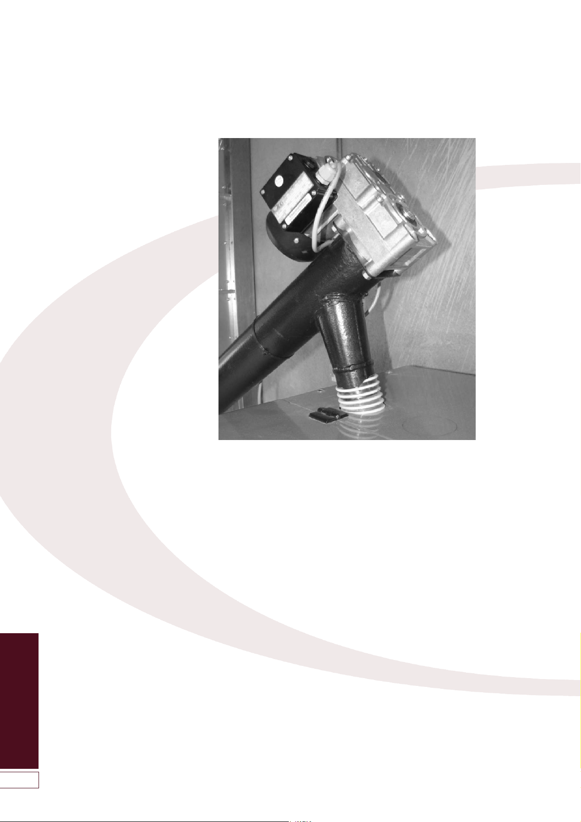
7.3.1 Fan Box & Flue Starter
The fan box supplied with the boiler
(packed in the accessories carton)
incorporates:
• Flue exhaust fan
• Draught stabiliser
• Flue starter connection (to fit Grant
‘Black’ flue system)
• Clean out hatch
The fan box is supplied with a neoprene
gasket for connection to the boiler. This
neoprene gasket is to accommodate
the low temperature wet flue system of
the Grant SPIRA boilers. Refer to
Section 4.15 for fitting details.
The lead for the flue fan (supplied
factory-fitted to the fan box) is
connected to the same 5-way plug as
the lead for the wash system solenoid
valve. Refer to Section 4.15 for
connection details.
When fitting the flue system to the flue
starter connection, on the fan box, the
lip seal supplied with the flue
component must be fitted to the inner
flue liner, and the locking band fitted to
secure the joint.
When installed, the draught stabiliser
must not be boxed in or obstructed
from operation in any way.
The clean out hatch allows access to
the inside of the fan box for inspection
and, where necessary, removal of any
ash that may have dropped down
inside the flue system. The clean-out
hatch MUST be correctly fitted during
normal boiler operation. See Section 10
-Servicing.
A condensate drain at the base of the
flue is not required as the flue system is
designed to allow the condensate to
run back into the boiler.
7.3.2 Flue System
The Grant ‘Black’ flue system is a fully
insulated stainless steel twin-wall flue finished with a Black Polyester Powder
paint finish. This insulated flue system
reduces the possibility of the
condensate freezing in the flue, and
also has a high corrosion resistance
suitable for solid fuel.
The 125mm (5in) ‘Black’ twin-wall flue
system is suitable for BOTH the SPIRA
6-26 & 9-36 models.
Masonry chimneys MUST be lined
using the 125mm stainless steel flexible
‘smoothbore’ liner – available as part of
the ‘Black’ system - due to the
condensate produced from the boiler.
6.3.3 Joining Components
All the ‘Black’ system twin-wall flue
components (with the exception of the
elbows) use a ‘twist lock’ jointing
system.
The ‘male collar’ end of the flue
component MUST always be
uppermost when fitted.
To join two components together:
First fit the lip seal supplied into the
groove (in the inner flue liner) at the
‘female collar’ end of the flue
component to be fitted.
All flue joints must have a lip seal
gasket fitted. The lip seal should be
fitted dry and the lubricating grease
(supplied with the component) applied
to the internal surface of the socket into
which it is to be fitted.
Loosen the locking band at the ‘female
collar’ end. Insert the ‘male collar’ into
the ‘female collar’ and twist through 1/6
of a turn to lock in place. Refer to
Figure 7-3.
!
NOTE
The Grant BLACK flue system is the
ONLY flue system suitable for use
with the Grant SPIRA Wood pellet
boilers. The use of other flue
systems will invalidate the product
warranty on the boiler.
Figure 7-2: Male and female flue connections
Male
collar
Insulation
Female
collar
Stainless
steel outer
case
Stainless
steel
inner liner
Capillary
break

Flue System and
Air Supply
26
Ensure that the two beaded ends of the
flue components are in contact with
each other all round. Position the
locking band so that it grips the beaded
edge of both components and fasten
using the spring clip. The locking bands
provided MUST be fitted at ALL flue
joints. Refer to Figure 7-4.
To temporarily assemble the flue system
components, to check component
lengths, alignment of connections, etc.
DO NOT fit the lip seals. However, for
FINAL assembly the lip seals provided
MUST be fitted at EVERY joint.
7.3.4 Adjustable Length
The Grant ‘Black’ flue system includes
an Adjustable flue extension. Refer to
Section 7.6. This allows any of the
straight flue extension components to
be extended in length by between
75mm to 250mm.
This adjustable extension must be used
in conjunction with any straight
extension (1000mm, 500mm or
333mm) to achieve the actual straight
length required.
To fit the adjustable extension, first
remove insulation from between the
inner and outer walls of the component,
as necessary. Fit the open end over the
‘male collar’ end of the fixed extension
and adjust to achieve the required
overall length. Secure the two
components together using the wide
locking band supplied.
7.3.5 Support Components
The weight of the flue system is
considerable. It must NOT be carried by
the fan box fitted to the appliance, but
requires independent support.
Support Plate
On internal systems, the weight can
often be supported where the flue
passes through an upstairs floor, using
the Support Plate with clamp band
(Grant ref. WP/SP). A four-sided square
opening, formed by timber stringers
between the joists, is required to
support the plate. Ensure that the
minimum distance of 60mm is achieved
between the flue outer surface and the
any combustibles (e.g. timber joists).
A Fire Stop plate (Grant ref. WP/FP) is
also required to be fixed to the ceiling
below.
When passing through a second
upstairs floor (in a 3-storey house)
either a second support plate can be
fitted or only two fire-stop plates (one
above and one below) need be fitted as
the flue is adequately supported at the
first upstairs floor level.
Intermediate Top Plate
Flue systems running up against either
an Internal or external wall surface can
be supported using the Intermediate
Top Plate (Grant Ref. WP/TP). This is
mounted on a pair of Wall Support Side
Plates (Grant Ref. WP/WS), which are
fastened to the wall, to provide support
at either the base, or part way up, a
vertical section of flue.
The ‘female collar’ (on the underside of
the plate) is fitted into the flue below
and the ‘male collar’ (on the upper side
of the plate) is a twist-lock connection
into the flue above. Both joints are
secured using the clamp bands
provided.
Wall and Roof Brackets
Both the Wall bracket (Grant ref.
WP/WB50) and the Adjustable Wall
Bracket (Grant ref. WP/WB300) are
NOT load bearing and are designed to
give lateral support only. Wall brackets
should be fitted with a maximum
spacing of 3m on straight runs of flue
and at any offset to ensure the system
is rigidly supported.
Similarly, the Roof Support Band (Grant
ref. WP/RS) is not load bearing and is
designed to give lateral support only.
Where the flue is free standing above
the roof and its height exceeds 1.5m
beyond the last support of the roof (e.g.
Roof Support Band) a Guy Wire
Bracket (Grant ref. WP/GB) MUST be
used and at every 1.5m thereafter.
Grant do not supply the guy wires or tie
rods to use with this bracket.
To allow for alignment, the female
collars of the elbows do NOT have the
twist lock flutes, but the locking band
MUST still be used to secure the two
flue components together.
Figure 7-3: Twist lock joint between
components
Figure 7-4: Fitting of locking band
7 Flue System and Air Supply
Locking band
All joints in the flue system must be
accessible for inspection. No joints
should be located within a wall, floor
or ceiling spaces or any other
inaccessible place.
!
WARNING
!
NOTE
The adjustable section is not loadbearing, therefore adequate support
of the flue system MUST be provided
immediately above the adjustable
extension.
 Loading...