

Grant Solo Compact, Solo CompactMAX, Solo Hideaway Installation And User Instructions Manual
Page 1

UK | DOC 0139 | Rev 1.0 | October 2018
Grant Solo
Fan Convectors
Installation and User Instructions
Page 2

Page 2
GRANT ENGINEERING (UK) LIMITED
Hopton House, Hopton Industrial Estate, Devizes, Wiltshire, SN10 2EU
Tel: +44 (0)1380 736920 Fax: +44 (0)1380 736991
Email: [email protected] www.grantuk.com
This manual is accurate at the date of printing but will be superseded and should be disregarded if specifications and/or appearances are changed in the interests of continued product improvement.
However, no responsibility of any kind for any injury, death, loss, damage or delay however caused resulting from the use of this manual can be accepted by Grant Engineering (UK) Limited, the
author or others involved in its publication.
All good sold are subject to our official Conditions of Sale, a copy of which may be obtained on application.
© Grant Engineering (UK) Limited. No part of this manual may be reproduced by any means without prior written consent.
IMPORTANT NOTE FOR INSTALLERS
These instructions are intended to guide installers on the
installation, commissioning and servicing of the Grant Solo fan
convectors. After installion, leave these instructions with the user.
User instructions to guide users in the operation of the fan
convectors are given in Section X of these instructions.
SPECIAL TEXT FORMATS
The following special text formats are used in these instructions
for the purposes listed below:
! WARNING !
Warning of possible human injury as a consequence of not
following the instructions in the warning.
! CAUTION !
Caution concerning likely damage to equipment or tools
as a consequence of not following the instructions in the
caution.
! NOTE !
Used for emphasis or information not directly concerned
with the surrounding text but of importance to the reader.
PRODUCT CODES AND SERIAL
NUMBERS COVERED
The serial numbers used on Grant Solo fan convectors consist
of a twelve or thirteen digit code with the rst two or three digits
being the product identier.
For example:
G3H2818000027
These instructions cover the following product codes and serial
numbers:
Product code Serial number identier
SC03 - Solo Compact G3
SC06MAX - Solo CompactMAX G6
SCHW - Solo Hideaway G3H
Page 3

1 INTRODUCTION 4
1.1 General 4
1.2 Operating principles 4
1.3 Control panel overview 5
2 TECHNICAL DATA 6
2.1 Fan convector technical data 6
2.2 Performance data 6
3 INSTALLATION 7
3.1 Introduction 7
3.2 Regulations 7
3.3 Location 7
3.4 System requirements 7
3.5 Pipework materials 8
3.6 Pipe connections 8
3.7 Installation procedure: 8
Solo Compact and Solo
CompactMAX models
3.8 Installation procedure: 9
Solo Hideaway model
4 ELECTRICAL 11
4.1 General 11
4.2 Electrical connections 11
Contents Page 3
5 COMMISSIONING 11
6 FAULT FINDING 12
6.1 Initial checks 12
6.2 Fault diagnosis ow chart 13
7 SPARES PARTS 14
7.1 Fan convector parts list 14
8 OPERATING INSTRUCTIONS 14
8.1 Mains ON/OFF switch 14
8.2 Control panel 15
9 CLEANING 15
10 DECLARATION OF CONFORMITY 16
11 HEALTH AND SAFETY INFORMATION 16
12 END OF LIFE INFORMATION 17
13 GUARANTEE 18
CONTENTS
Page 4

Section 1: IntroductionPage 4
1.1 GENERAL
The Grant Solo range consists of two wall-mounted fan
convectors, the Grant Solo Compact and Grant Solo
CompactMAX, and the Grant Solo Hideaway model designed to t
under kitchen units or in other similar locations.
For heating capacity details on all three models refer to Section 2
of these Instructions.
Grant Solo fan convectors are supplied with a simple electronic
control panel. Refer to Section 10 for further details and operating
instructions. Each fan convector is individually controlled to
provide a exible and responsive means of heating each space.
They are designed to be integrated into low temperature heating
systems using air source heat pumps, condensing oil, gas and
biomass boilers, etc.
Each Solo fan convector requires a 3A fused 230V 1ph 50Hz
electrical supply. Refer to Section 5 for further details.
A double pole mains ON/OFF switch is factory tted to all Grant
Solo units.
On the Solo Compact and CompactMAX models this is located
under the right-hand end of the front casing. On the Solo
Hideaway model this switch is located on the right-hand side of
the unit.
The steel chassis of the Solo Compact and Solo CompactMAX is
xed directly to the wall. No wall mounting brackets are required,
keeping the unit as close to the wall as possible.
With the Solo Hideaway unit, the steel chassis is xed directly to
the plinth or similar when tting under kitchen units or other xed
units.
Figure 1-1: Solo Compact and CompactMAX wall hung fan
convector
Figure 1-2: Solo Hideaway fan convector
1.2 OPERATING PRINCIPLES
The Grant Solo range of fan convectors use backward curved
impellers and they are designed to ensure zero convection and
therefore minimal heat emission when the fan is not running. This
eliminates the need for any radiator control valves.
The heat exchanger does not touch the outer case but is insulated
from it, providing a low casing surface temperature regardless of
the water ow temperature. The top grille prevents contact with
the heat exchanger.
With the electrical supply to the Solo fan convector switched
on; when the water temperature sensor (located in the heat
exchanger) detects that the water temperature entering the unit
exceeds 29°C the unit will start.
The air temperature is then sampled over a 60 second period by
the air temperature sensor located at the rear of the unit.
The user can then set the required room air temperature between
18 to 24°C via the control panel on the front of the unit. Refer to
Section 10 - Operating Instructions for further details on setting
the required air temperature.
The Grant Solo microprocessor control system predicts the air
temperature at occupant level as low-level temperatures are
always colder than at occupant level and would provide incorrect
data on which to determine the level of heat output required.
If the difference between the sampled air temperature and the air
temperature setting on the unit is greater than 1°C the heat output
of the unit is increased with the fan running on the ‘High’ setting.
When the air temperature rises and the difference between the
sampled air temperature and the air temperature setting on the
unit is less than 1°C the heat output is decreased with the fan
running on the ‘Low’ setting.
When the air temperature reaches the setpoint, the unit is
switched off and enters a ‘sleep’ period for 8 minutes. After this
the air temperature is then sampled over a 60 second period.
If there is no change and no heat output is required, the unit
enters an 8 minute ‘sleep’ period again before sampling the
air temperature for 60 seconds again, until a difference exists
between the sampled air temperature and the air temperature
setting on the unit.
The Grant Solo unit will then repeat the start-up sequence again.
1 INTRODUCTION
Control panel
Mains ON/OFF switch
located on underside of unit
Control panel
Mains ON/OFF switch located on
underside of unit (not shown)
Page 5

Section 1: Introduction Page 5
BOOST FUNCTION
The boost function is activated by pressing the Boost button
on the control panel fascia. Refer to Section 10 - Operating
Instructions.
The boost function overrides the normal temperature control and
runs the fan at higher ‘Boost’ level for a period of 20 minutes to
provide a greater heat output than the normal operation.
After this period has elapsed the Solo unit automatically returns
to the normal temperature control with the fan operating at either
‘Low’ or ‘High’ setting as dictated by the difference between the air
temperature and the air temperature setting on the unit.
1.3 CONTROL PANEL OVERVIEW
Grant Solo fan convectors are supplied with a simple control
panel. Refer to Figure 1-3 and Section 8.2 (control panel).
Temperature indicator lights
ON/OFF
button
Alarm light
Special function
light
Boost / cool button
Figure 1-3: Solo fan convector control panel overview
Page 6

2.1 FAN CONVECTOR TECHNICAL DATA
Table 2-1: Fan convector technical data
Units Solo Compact Solo CompactMAX Solo Hideaway
Height mm 410 410 120
Width mm 610 985 700
Depth mm 110 110 418
Water content litres 0.15 0.30 0.15
Weight (empty) kg 8.2 13.8 6.6
Weight (full) kg 8.35 14.1 6.75
Flow and return pipe size mm 15 15 15
Maximum water temperature °C 85
Maximum water pressure bar 10
Electrical supply ~230 1ph 50Hz 3A fused
Power input
Low speed W 8 13 8
High speed W 10 19 10
Boost W 20 36 20
Standby power W 4 4 4
Sound pressure level at 1 metre (ISO 3744)
Low speed dB(A) 18 18 18
High speed dB(A) 22 23 22
Boost dB(A) 38 39 38
2.2 PERFORMANCE DATA
Table 2-2: Heating capacity (BS EN ISO 16430) on high/low fan speed
Mean water
temperature*
Units
Solo Compact Solo CompactMAX Solo Hideaway
High Low High Low High Low
35°C W 314 247 604 470 314 247
40°C W 426 335 831 646 426 335
45°C W 542 426 1,071 832 542 426
50°C W 660 519 1,318 1,024 660 519
55°C W 780 613 1,570 1,220 780 613
60°C W 901 708 1,828 1,420 901 708
65°C W 1,023 803 2,090 1,623 1,023 803
70°C W 1,146 900 2,356 1,830 1,146 900
* Mean water temperature = (ow temperature + return temperature) ÷ 2
Section 2: Technical DataPage 6
2 TECHNICAL DATA
Page 7

Section 3: Installation Page 7
3.1 INTRODUCTION
Each Solo fan convector requires a 3A fused 230V 1ph 50Hz
electrical supply and is tted with a terminal block for easy and
quick electrical connection. Refer to Section 5 for further details.
Please ensure that Solo fan convectors are protected from dirt,
rubble, etc. and it is suggested to wait for all other building and
decorating works to be completed before nally xing in the
required location.
3.2 REGULATIONS
The Installation of a Grant Solo fan convector must be in
accordance with the following recommendations:
• Building Regulations for England and Wales or the Building
Standards for Scotland, as appropriate.
• Any local Byelaws which you must check with the local
authority for the area concerned.
• The Water Supply (Water Fittings) regulations 1999 or
the water Supply (Fittings) (Scotland) Bylaws 2014, as
appropriate.
• Applicable Control of Pollution Regulations.
The installation should also be in accordance with the latest
edition of the following British Standard Code of Practice (and any
relevant amendments):
• BS EN 12828 (Heating systems for buildings. Design for
water-based heating systems).
• BS EN 14336 (Heating systems in buildings. Installation and
commissioning of water-based heating systems).
• BS 7593 (Code of Practice for treatment of water in domestic
hot water central heating systems).
• BS 7671 (Requirements for Electrical installations, IET Wiring
Regulations).
• BS 7291 (Thermoplastic pipe and ttings systems for hot and
cold water for domestic purposes and heating installations in
buildings. General requirements.
• BS 7074-1 (Application, selection and installation of
expansion vessels and ancillary equipment for sealed water
systems. Code of practice for domestic heating and hot water
supply.
3.3 LOCATION
Solo Compact and CompactMAX fan convectors should be
positioned with the lower edge approximately 75-100mm above
the skirting level.
The Solo Hideaway fan convectors are tted into the plinth or
baseboard of xed units, e.g. kitchen units. Refer to Section 3.7
for dimension of the opening required. The lower edge of this
opening must be at least 12mm above the nished oor level.
The outlet from all Solo fan convectors must be unrestricted, e.g.
no shelves above the wall hung Solo Compact and CompactMAX
units.
Ensure that heating system ow/return pipework is not run along
the wall or skirting directly below either the Solo Compact or
Solo CompactMAX fan convectors. The warm air rising from the
pipework will affect the operation of the air temperature sensor
tted at the rear of the fan convector and may result in reduced
heat output from it.
3.4 SYSTEM REQUIREMENTS
Grant Solo fan convectors can be used on either open vented or
sealed central heating systems.
The pressure characteristics of the Grant Solo fan convectors
were designed to facilitate even ow sharing by ensuring that
the pressure drop at various ow rates considerably exceeds the
pipework friction loss.
Care must therefore be taken to ensure that adequate pumping
capacity exists to guarantee adequate ow through each fan
convector unit. A 6metre head pump is suggested.
A maximum of approximately six to eight Solo units on a circuit,
with 22mm ow and return pipework with 15mm radiator tails, is
recommended.
It is suggested that reverse return pipework be used where
possible. Refer to Figure 2-4.
Figure 3-1: Conventional ow/return piping
Figure 3-2: Reverse return piping
3 INSTALLATION
3 way valve
Hot water cylinder
EV
Flow
Return
3 way valve
Hot water cylinder
EV
Flow
Return
Page 8
Section 3: InstallationPage 8
OPERATION WITH RADIATORS
Grant Solo fan convectors are ultra-low water content heat
emitters and should ideally not share heating circuits with
conventional radiators, as this may result in a reduced ow
through the fan convectors.
If this cannot be avoided and the fan convectors must be added
to an existing radiator circuit the following requirements must be
met:
a) The ow and return pipework must be 22mm minimum.
Smaller pipework will result in poor or no heat output from the
fan convector(s).
b) When installed, rst shut off the conventional radiator(s) to
check that the fan convector(s) operate correctly.
Then, turn on the radiator(s) and adjust the lockshield valve
on each radiator and reduce the ow until the fan convector(s)
operate.
3.5 PIPEWORK MATERIALS
The Grant Solo fan convectors can be used with both copper
and plastic pipe. Where plastic pipe is used it must be of the
oxygen barrier type and be the correct class (to BS7291-1) for the
application concerned.
On sealed systems, if plastic pipe is to be used, the installer must
check with the plastic pipe manufacturer that the pipe to be used
is suitable for the temperatures and pressures concerned. Plastic
pipe must be Class S to BS7291-1.
Two exible hose connections will be required for installation of
the Grant Solo Hideaway fan convector. These are supplied with
the unit.
3.6 PIPE CONNECTIONS
SOLO COMPACT AND COMPACTMAX MODELS:
Remove the front cover to access the ow and return pipe
connections. Refer to Section 3.6 or 3.7, as required, for details
on removal of the front cover.
The ow and return connections are located at the left-hand side
of the unit.
The ow and return pipework can enter/exit the unit either
a) To the rear of the unit through the wall, or
b) To the bottom of the unit, through the opening in the lower
casing.
It is recommended that 15mm isolation valves (not supplied)
are tted to the ow and return connections before connecting
the ow and return pipework. These valves must be of the ‘full
bore’ type to ensure no added restriction to the ow and return
pipework.
SOLO HIDEAWAY:
The ow and return connections are located on the right-hand
side of the unit.
To allow the unit to be fully withdrawn from the plinth or base
board in which it is tted, without having to disconnect it from the
system, two exible hose connections (supplied) will be required
for installation of the Grant Solo Hideaway fan convector. These
are long enough to allow the fan convector to be completely
removed from the plinth/baseboard when they are connected.
These will be connected between the system ow and return
pipework, located at the rear of the xed kitchen unit, and the 15
mm full bore valves on the ow and return connections on the fan
convector.
3.7 INSTALLATION PROCEDURE:
SOLO COMPACT AND SOLO
COMPACTMAX MODELS
1. Carefully remove the Solo fan convector unit from the
packaging.
2. Lay the unit on a at surface (oor, table, etc.) with the front
cover facing upwards.
3. Unscrew and remove the three xing screws from along the
lower edge of the front cover.
4. Lift the lower front edge of the front cover and then slide it
forwards and off the unit.
5. Safely store the front cover for now where it will not be
damaged or scratched for re-tting after the Solo Compact or
CompactMAX fan convector has been installed.
6. Position the unit against the wall so that the lower edge is
approximately 75-100mm above the skirting level.
7. Use a spirit level on the top of the unit to ensure it is level
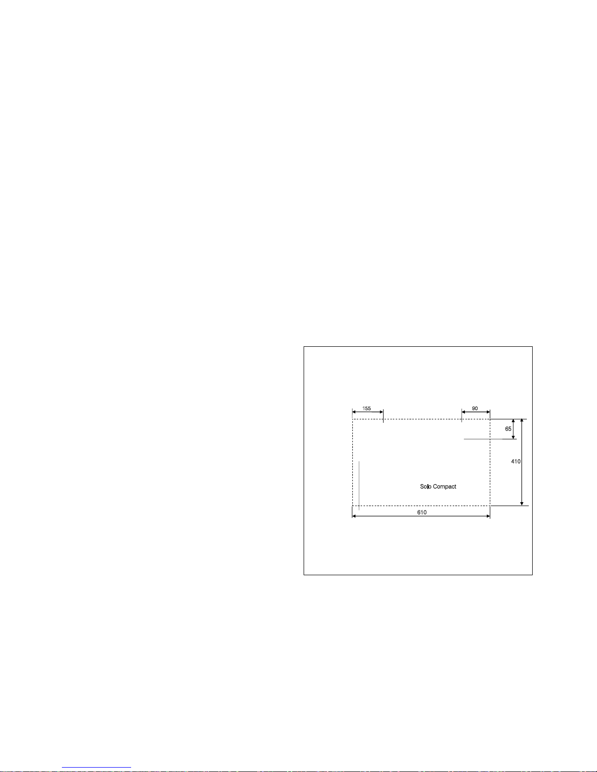
and mark the position of the three xing holes in the back
plate onto the wall. Refer to Figure 2-5 0r 2-6 for the xing
hole positions.
8. Remove the unit from the wall and drill the three holes to take
a suitable wall xings (not supplied).
9. Securely x the unit to the wall using three screws (not
supplied).
10. Remove the rubber bungs from the ow and return
connections on the fan convector and check that the bleed
screws on the ow connection are both closed.
It is recommended that 15mm isolation valves (not supplied) are
tted to the ow and return connections before connecting the
ow and return pipework.
These valves must be of the ‘full bore’ type to ensure no added
restriction to the ow and return pipework.
Solo Compact
410
610
Outline of front cover
65
90
155
Figure 3-3: Solo Compact xing holes (viewed from the front)
Page 9
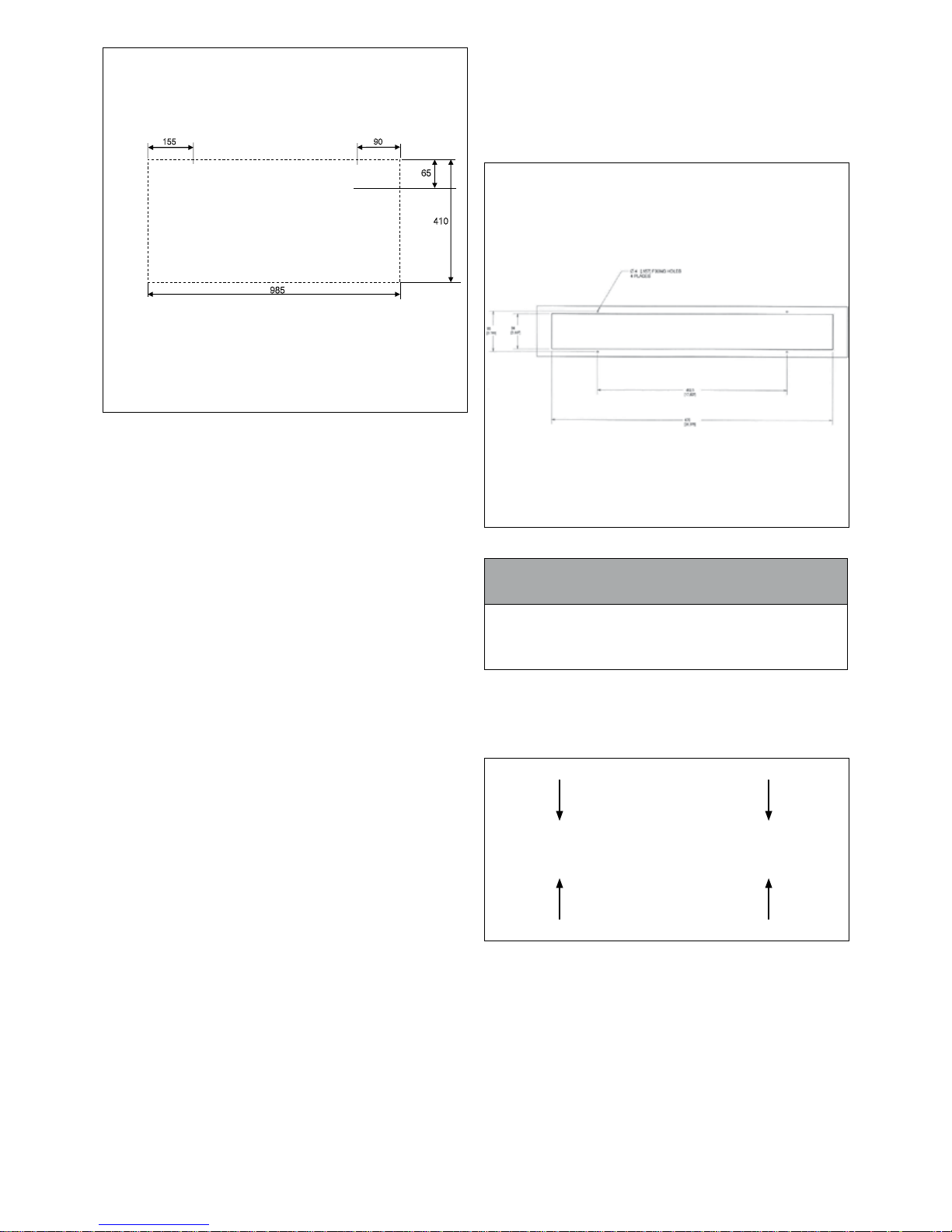
985
410
Outline of front cover
65
90
155
Figure 3-4: Solo CompactMAX xing holes (viewed from the
front)
11. Connect the heating system ow and return pipes to the
corresponding ow and return connections on the Solo fan
convector unit via the isolation valves.
12. Connect the electrical supply to the Solo fan convector unit.
Refer to Section 4 (Electrical).
13. When all the Solo fan convectors have been connected to
the system pipework, the system can be lled.
14. Once the system is lled, open the HIGHEST of the two
bleed screws on the ow pipe to vent the fan convector heat
exchanger. Repeat this with all other fan convectors on the
system.
15. Ret the front cover and secure along the lower front edge
using the three screws previously removed.
16. When all the installation of all the Solo fan convectors has
been completed they can be commissioned. Refer to Section
5 (Commissioning).
3.8 INSTALLATION PROCEDURE:
SOLO HIDEAWAY MODEL
Accurately mark and cut the opening required in the plinth or
panel into which the Grant Solo Hideaway unit is to be tted. The
bottom edge of the opening MUST be at least 12mm above the
nished oor level.
Refer to Figure 2-7 for the dimensions of the opening.
Figure 3-5: Solo Hideaway cut-out and xings holes
! NOTE !
If the height of the opening above oor level is greater than
12mm, it may be necessary to place packing under the two
rubber feet at the rear of the fan convector to support the
unit.
Carefully remove the Solo Hideaway fan convector unit from the
packaging and lay it on a at surface.
Unscrew and remove the four xing screws. Refer to Figure 2-8.
Keep these screws in a safe place as they will be required later to
re-t the grille.
Figure 3-6: Solo Hideaway grille xing screws
Carefully remove the grille and lay it at in front of the unit.
Disconnect the control panel ribbon connector from the plug.
Refer to Figure 2-9.
Section 3: Installation Page 9
Page 10

Figure 3-7: Solo Hideaway control panel ribbon connector and
plug
Disconnect the air temperature sensor lead at the small plug.
Refer to Figure 2-10.
Figure 3-8: Solo Hideaway air temperature sensor and plug
Once disconnected, safely store the front grille for now where
it will not be damaged or scratched for re-tting after the Solo
Hideaway fan convector has been installed.
Position the Solo Hideaway unit into the opening in the plinth/
baseboard. Mark the centres of the four xing holes. Refer to
Figure 2-5.
Withdraw the Solo Hideaway unit from the plinth/baseboard and
drill the four xing holes to suit the xing screws to be used (not
supplied).
Remove the rubber bungs from the ow and return connections
on the fan convector and check that the bleed screws on the ow
connection are both closed.
It is recommended that 15mm isolation valves (not supplied)
are tted to the ow and return connections before connecting
the ow and return pipework. These valves must be of the ‘full
bore’ type to ensure no added restriction to the ow and return
pipework.
Connect the heating system ow and return pipes to the
corresponding ow and return connections on the Solo fan
convector unit using the two exible hoses (supplied). These are
long enough to allow the fan convector to be completely removed
from the plinth/baseboard when they are connected.
Connect the electrical supply to the Solo fan convector unit. Refer
to Section 4 (Electrical).
! NOTE !
Do NOT t the Solo Hideaway unit into the opening until
the system has been lled and the fan convector(s) vented.
When all the Solo fan convectors have been connected to the
system pipework, the system can be lled.
Once the system is lled, open the HIGHEST of the two bleed
screws on the ow pipe to vent the fan convector heat exchanger.
Repeat this with all other fan convectors on the system.
Set the mains ON/OFF switch, on the right-hand side of the unit,
to ON.
Position the Solo Hideaway unit into the opening and carefully
push fully into place.
! NOTE !
Ensure that the space into which the Solo Hideaway is
being tted is clear of any debris, uff, dust, etc.
Whilst tting the fan convector into the opening ensure that the
exible hoses are not kinked or twisted.
Secure the Solo Hideaway unit to the plinth/baseboard using four
screws (not supplied) in the previously drilled holes.
Lay the grille face down in front of the Solo Hideaway unit.
Reconnect the control panel ribbon connector and the air
temperature sensor lead at the small plug.
Position the grille on the front of the Solo Hideaway unit and
secure using the four xing screws previously removed.
Carefully remove the protective covering from the grille.
When all the Solo fan convectors have been installed they can be
commissioned. Refer to Section 5 - Commissioning.
Section 3: InstallationPage 10
Page 11
Section 4: Electrical and Section 5: Commissioning Page 11
4.1 GENERAL
Grant Solo fan convectors require a ~230V 1ph 50Hz electrical
supply protected by a 3 Amp fuse.
A fused double pole switch, with contact separation of at least
3mm in both poles, should be used for connection to the mains
electrical supply, serving the boiler and heating system controls
only.
For the Solo Compact and Solo CompactMAX this switch can be
located on the wall next to the fan convector.
For the Solo Hideaway, this switch can be located in a convenient
position for the user to access when necessary, e.g. on the wall
above kitchen unit/worktop level or inside the kitchen unit.
For the UK, the electrical installation must be carried out by a
competent installer in accordance with the requirements of the
Electricity at work Regulations 1989 and BS7671:2018 – IET
Wiring Regulations 18th Edition.
If installed in the Republic of Ireland, the wiring installation must
comply with all ETCI rules. All the wiring and supplementary earth
bonding external to the boiler must be in accordance with the
above-mentioned wiring regulations.
Do NOT interrupt the electrical supply to the Grant Solo with any
external controls.
4.2 ELECTRICAL CONNECTIONS
Connect the electrical supply to the fan convector as follows:
SOLO COMPACT AND SOLO COMPACTMAX
Remove the front cover from the fan convector (if not already
removed).
To do this, unscrew and remove the three xing screws from
along the lower edge of the front cover.
Pull outwards the lower front edge of the front cover and then lift it
off the unit.
The electrical supply terminal block is located at the lower righthand side of the fan convector. Refer to Figure 4-1.
Pass the cable through the hole with grommet and the cable
restraint – both located at the right-hand end of the fan convector.
See Figure 4-1.
Connect the mains supply cable (from the fused double pole
switch) to the terminal block as follows:
• Terminal L: Live – Brown wire
• Terminal N: Neutral – Blue wire
• Terminal P
E: Earth – Green/yellow wire
Secure the cable in the cable restraint to prevent it being pulled
out of the terminal block.
Replace the front cover on the fan convector and secure with the
three screws along the lower edge.
Switch on the electrical supply to the fan convector at the fused
double pole switch.
SOLO HIDEAWAY
The Solo Hideaway is supplied with a pre-wired 1mm2 3-core
cable 1,300mm long for connection to the electrical supply.
This can be connected directly to a fused double pole switch
located under the kitchen unit.
Alternatively, a 3-pin 13A plug (tted with a 3A fuse) can be tted
to the cable for connection to a 3-pin socket under the kitchen
unit and this socket is fed from a fused double pole switch located
either within a kitchen unit or above the worktop level, as required.
Switch on the electrical supply to the fan convector at the fused
double pole switch.
4 ELECTRICAL
Ensure that the system is lled and vented and that each Solo fan
convector has also been vented. Refer to either Section 3.6 or 3.7
as required.
Switch on the mains electrical supply to the fan convector at the
fused isolator.
Switch the mains ON/OFF switch to ON.
On the Solo Compact and CompactMAX models, the mains
switch is located under the right-hand end of the front casing.
Refer to Figure 8-1.
On the Solo Hideaway model, the mains switch is located on the
right-hand side of the unit and should have been set to the ON
position before being nally tted in to the plinth/baseboard. Refer
to Figure 8-2.
Switch the boiler or heat pump on and set the heating system
controls to call for heat.
Operate the heating system to raise the ow temperature
REFERRING TO SECTION 8 – OPERATING
INSTRUCTIONS
Check the operation of the Solo fan convector(s) as follows:
Press and hold the ON/OFF button on the Solo fan convector
control panel to switch the unit on.
The Alarm/Boost light will ash until the water ow temperature
reaches 29°C.
When the ow temperature reaches at 29°C the Alarm/Boost light
will stop ashing and one of the temperature Indicator lights will
be lit – either ashing or constant.
Using the ON/OFF button, set the air temperature to each one of
the four settings in turn to check their operation and then nally
set the air temperature to the required setting.
! NOTE !
It is NOT possible to adjust the temperature setting if the
water ow temperature is at less than 29°C.
Press the Boost/Cool button to check the boost function operation.
Press the Boost/Cool button again to switch the boost function off.
Set the heating system controls to the user’s requirements.
5 COMMISSIONING
Page 12
Section 6: Fault FindingPage 12
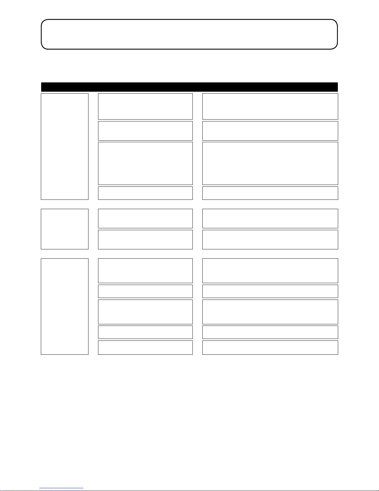
6.1 INITIAL CHECKS
If your Grant Solo fan convector appears not to be operating correctly, please rst carry out the following simple checks before seeking
further assistance.
Symptoms Check Actions
No heat output from
fan convector
Are there any lights on the control panel? ►
If NO:
Check mains ON/OFF switch is set to ON
Check power supply to unit is switched ON at fused isolator switch
Check fuse in power supply fused isolator
Is the Alarm/Boost light ashing?
(refer to Section 8.2)
►
If YES:
Heating system water temperature is less than 29°C (refer to
Section 8.2).
Is the boiler or heat pump operating? ►
If NO:
Check the boiler/heat pump controls are correctly set for it to
operate
If the boiler/heat pump is faulty, contact your installer/service
engineer
If YES:
Wait for the system water temperature to reach at least 29°C.
Is the heating system circulating pump
operating?
► Check and contact your installer to investigate if there is a problem
Low room
temperature
Is the required air temperature correctly set on
the control panel?
(refer to Section 8.2)
►
Set required air temperature using the ON/OFF button on the
control panel.
Is the required temperature setting indicator
light ashing?
(refer to Section 8.2)
►
Set point temperature has not yet been reached. Wait until indicator
light stops ashing
Low heat output from
fan convector
Is the water ow through the fan convector
too low?
►
Check for low water ow
A simple test for low ow is if there is a noticeable temperature
difference to the touch between the ow and return pipes when the
unit is operating
Are the isolating valves on the ow and return
connections open?
► Check and open valves if necessary
Are the ow and return connections reversed? ►
Check - the ow and return connections are indicated on the fan
connector.
The ow pipe should be hotter to the touch than the return pipe
when the unit is operating
Has the fan convector been completely bled
of air?
►
Check by bleeding any remaining air - as described in either Sections 3.7 or 3.8, as appropriate for the model of fan convector.
Are the exible hoses twisted or kinked
(Solo Hideaway model only)?
►
Remove unit from plinth and check. Rectify as necessary.
(Refer to Section 3.7)
6 FAULT FINDING
Page 13
Section 6: Fault Finding Page 13
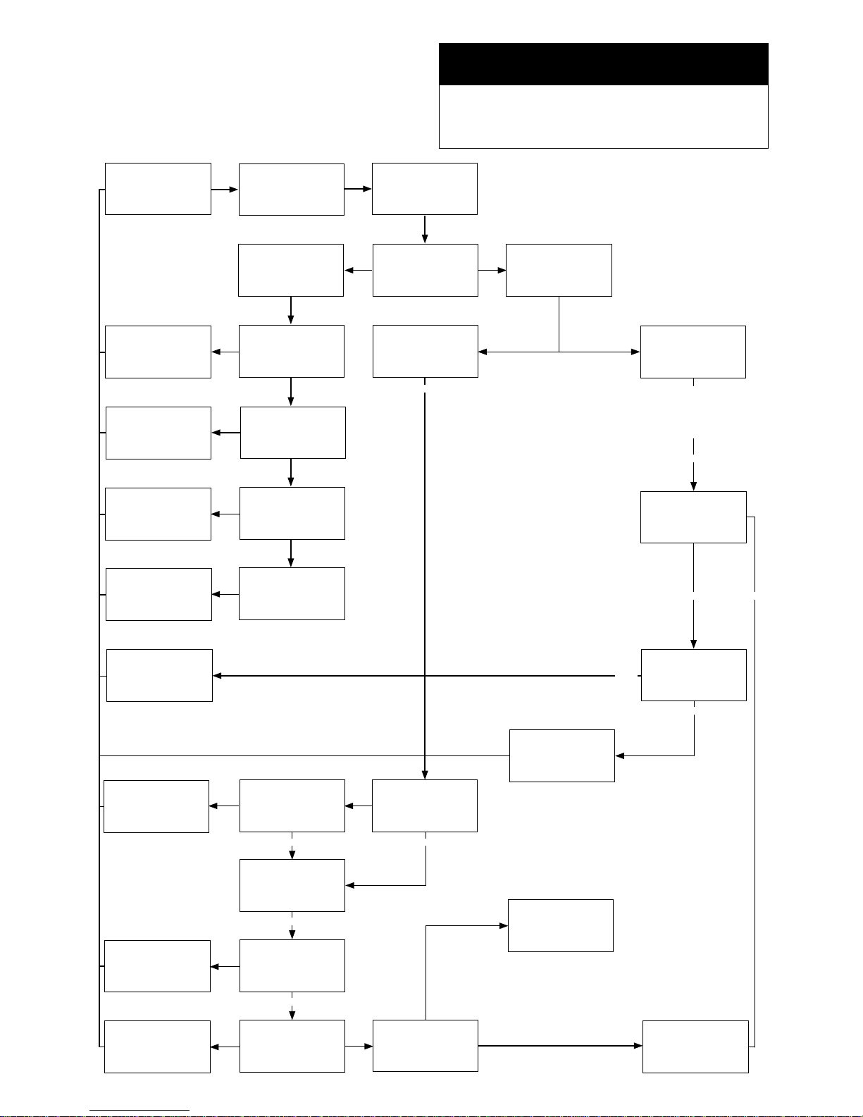
6.2 FAULT DIAGNOSIS FLOW CHART
The following owchart can be used to determine and rectify a
fault in the operation of a Grant Solo fan convector.
Please rst carry out the simple checks, as detailed in Section
6.1, before using the ow chart below.
! WARNING !
Exposure to live electrical connections.
The following fault-nding procedures should only be
conducted by a suitably qualied competent person using
the correct test equipment.
START
Check electricity supply
is turned on at the
fused isolator.
Turn unit off and on
using the mains ON/
OFF switch
Electrical problem
230V AC at 3 way
terminal block
Are there any lights
illuminated on the
control panel?
Other problem
Fix issue with mains
power supply
230V AC after mains
ON/OFF switch
Replace mains ON/
switch (SP0068)
Power at grey and
white wires at PCB
~10V AC
Replace transformer
(SP0012)
Any lights illuminated
on the control panel
Replace power and
control PCB (SP0129)
and user interface PCB
(SP0128)
Boost light ashing
20°C indicator light
(2 bars) ashing?
Check fans are running
heat is being emitted
Check power on fan
output (blue wire) on
PCB ~50V AC
Replace transformer
(SP0012)
Check hot water supply
to Solo is above 29°C
Is the heat source
functioning correctly
Fix issue with heating
source
Check that the system
is balanced
Inlet pipe to the radiator
is above 29°C
Balance radiators on
the system to ensure
ow to the Solo
Air and water
temperature sensor
connected?
Re-connect sensor.
Replace temperature
sensor if necessary.
(SP0350)
Check fans are running
and heat is being
emitted
Contact your installer /
service engineer
PROBLEM
RESOLVED
Replace fan (SP28-
24) and capacitor
(2μF - SP0229 / 4μF -
SP0237)
NO YES
YES
NO
NO
YES
YES
YES
NO
NO
YES
NO YES
YES
NO
NONO
YESYES
YES
YES
YES
NO
NO
The air temperature sensor
can be disconnected at this
point to stimulate cold room
temperatures and force the
20°C indicator light (2 bars) to
ash and fans to run
Page 14
Section 7: Spare Parts and Section 8: Operating InstructionsPage 14
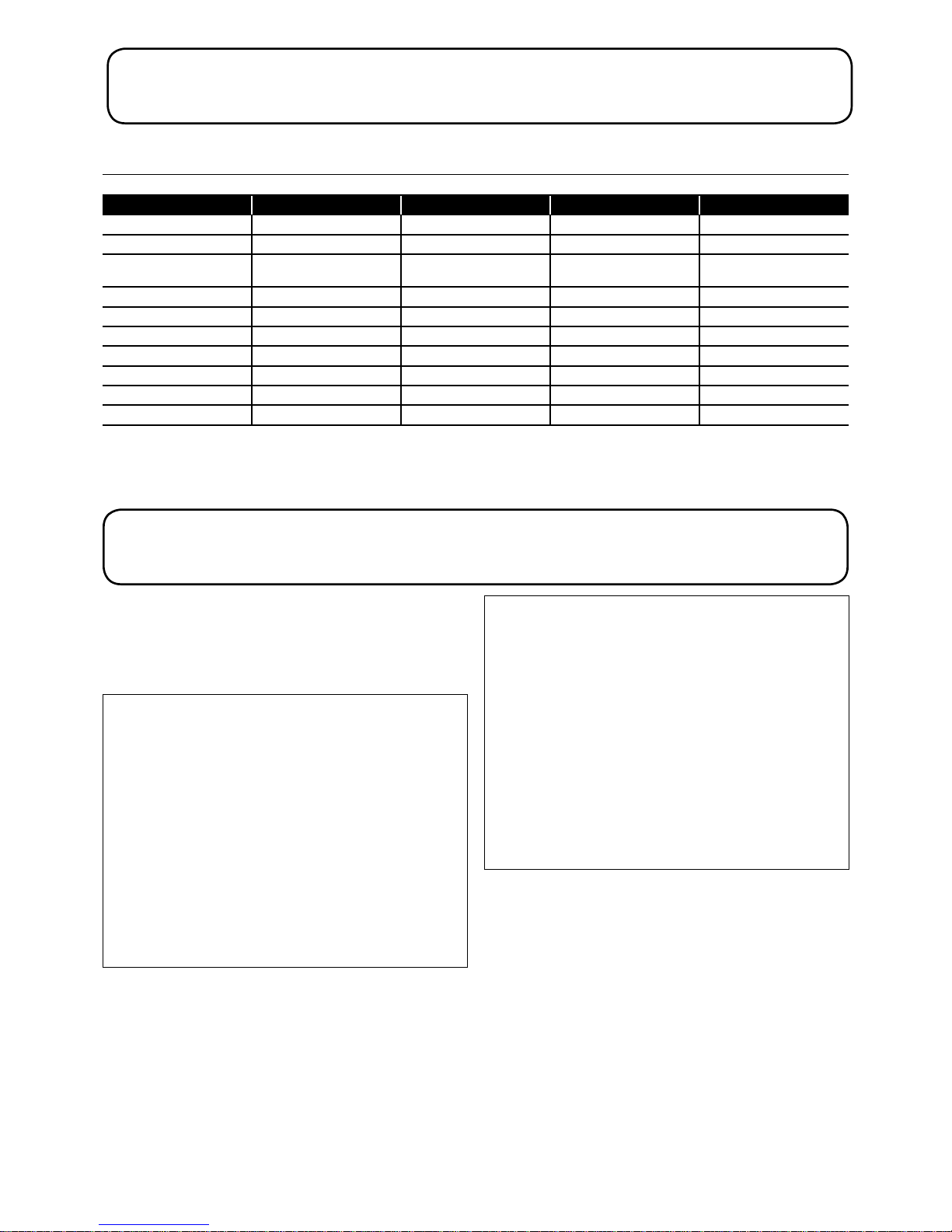
7.1 FAN CONVECTOR PARTS LIST
Table 7-1: Fan convector parts list
Description Grant UK product code Solo Compact Solo CompactMAX Solo Hideaway
User interface PCB SP0128 • • •
Power and control PCB SP0129 • • •
Plug-in microprocessor
board
SP0133 • • •
Mains ON/OFF switch SP0068 • • •
Fan SP28-24 • • •
Transformer SP0012 • • •
Temperature sensor SP0350 • • •
Capacitor 2μF SP0229 • •
Capacitor 4μF SP0237 •
Flexible hose - 900 mm SP-MB90 •
7 SPARE PARTS
8.1 MAINS ON/OFF SWITCH
Grant Solo units have a factory-tted double pole mains ON/OFF
switch.
SOLO COMPACT AND COMPACTMAX MODELS:
This switch is located under the right-hand end of the front casing.
Refer to Figure 10-1.
Figure 8-1: Solo Compact and CompactMAX mains ON/OFF
switch (underside of unit)
SOLO HIDEAWAY MODEL:
This switch is located on the right-hand side of the unit. It should
have been set to the ON position before being nally tted in to
the plinth/baseboard.
8 OPERATING INSTRUCTIONS
Figure 8-2: Solo Hideaway mains ON/OFF switch (right-hand
side of unit)
For the unit to operate, ensure that this switch is set to ON and
the power supply to the Solo fan convector is on, i.e. the switch on
the fused spur serving the unit is set to ON.
Page 15

Section 8: Operating Instructions and Section 9: Cleaning Page 15
8.2 CONTROL PANEL
Grant Solo fan convectors are supplied with a simple control
panel. Refer to Figure 1-3.
This allows each Solo unit to be individually set to suit the room or
area in which it is installed.
The functions of the buttons and indicator lights are as follows:
ON/OFF BUTTON
When the ON/OFF button is pressed for at least 1 second it will
start the operation of the Grant Solo unit – provided that the water
ow temperature is at least 29°C AND the room air temperature
is low enough (i.e. below the air temperature setting of the Solo
unit). See section on ‘Temperature indicator lights’ below.
To stop the unit operating, press the ON/OFF button for at least 1
second.
TEMPERATURE INDICATOR LIGHTS
There are four temperature indicator lights that display the air
temperature setting of the Solo unit, and whether that temperature
setting has been achieved or not.
These indicate increasing temperature settings from the lowest on
the left to the highest on the right, as follows:
• 18°C – indicator light with single bar
• 20°C – indicator light with two bars
• 22°C – indicator light with three bars
• 24°C – indicator light with four bars
TO SET THE REQUIRED AIR TEMPERATURE
Press the ON/OFF button momentarily – the lowest (single bar)
indicator light will ash slowly indicating that the air temperature
setting is 18°C.
TO INCREASE THE SETTING
Press the ON/OFF button again momentarily – the next (two
bars) indicator light will now ash slowly indicating that the air
temperature setting is now 20°C.
Press the ON/OFF button again momentarily to increase the
setting further (if required) – the next (three bars) indicator light
will now ash slowly indicating that the air temperature setting is
now 22°C.
Press the ON/OFF button again momentarily (if required) and the
right hand (four bars) indicator light will now ash slowly indicating
that the air temperature setting is now at the maximum (24°C).
Pressing the ON/OFF button again momentarily will return the
air temperature setting to the minimum (18°C) and the left hand
(single bar) indicator light will now ash slowly.
The selected indicator light will continue to ash slowly whilst the
temperature is being raised. When the air temperature reaches
the setpoint, the indicator light will stop ashing and become
continuous. The Grant Solo unit will then stop heating until
needed again.
! NOTE !
It is NOT possible to adjust the temperature setting if the
water ow temperature is at less than 29°C.
ALARM LIGHT
The Alarm light will ash if the water ow temperature is less than
29°C.
BOOST/COOL BUTTON
Press this button momentarily whilst the Solo unit is operating and
the normal Solo temperature control will be overridden for a period
of 20 minutes to provide a higher output than available in normal
operation.
The temperature indicator light will go off and the Alarm/Boost
light will come on to indicate the Solo unit is operating in the Boost
mode.
To stop the Boost function
Press the Boost button momentarily at any time during the 20
minute boost period.
After 20 minutes have elapsed, the Solo unit will automatically
revert to the normal temperature control. The Alarm/Boost light will
go off and the temperature indicator light will revert to the original
setting.
Momentarily pressing the Boost button again will re-start the boost
function for another 20 minutes.
SUMMER COOLING FUNCTION
In the summer Solo fan convectors can be used to provide air
movement to give passive cooling.
To use this function, press BOTH the ON/OFF and Boost buttons
at the same time for more than 1 second.
The water temperature control will be ignored and the fan will run
at the highest (boost) level for maximum air ow until the Solo unit
is switched off. The Alarm/Boost light will come on in this mode.
To switch off the summer cooling function, press BOTH the ON/
OFF and Boost buttons at the same time for more than 1 second.
! NOTE !
The Summer cooling function will NOT automatically
switch off after a xed period (as with the Boost function)
but will remain on until BOTH the ON/OFF and Boost
buttons are presses at the same time.
SPECIAL FUNCTION LIGHT
This light is not used and will not be lit during the operation of
the fan convector. This does NOT indicate a fault with the fan
convector.
Whilst it is not necessary for the Grant Solo fan convectors to be
regularly serviced, a limited amount of cleaning is required from
time to time.
Only use a moist cloth to clean the outer surfaces of the Solo fan
convectors. Do NOT use any abrasive cleaners, cleaning liquids
or aerosols.
9 CLEANING
The warm air outlet grille on the top of the Solo Compact and Solo
CompactMAX and the front grille of the Solo Hideaway can be
vacuumed clean.
The air inlet lters on the Solo Hideaway (located either side of
the warm air outlet grille) are not removeable or replaceable. They
can be vacuum clean from the front.
Page 16
Section 10: Declaration of Conformity and Section 11: Health and Safety InformationPage 16
EC DECLARATION OF CONFORMITY
We: Grant Engineering (UK) Limited
Hopton House
Hopton Industrial Estate
Devizes
SN10 2EU
Declare that:
Equipment: Solo Fan Convector Radiators
Model name/number: Solo Compact, Solo CompactMAX and Solo Hideaway
In accordance with the following Directives:
Low Voltage Directive: 2014/35/EU
EMC Directive: 2014/30/EU
Radiator and Convector Standards:
EN 442-2 1997
EN 16430-2 2014
EMC Standards:
EN 55014-1 2002
EN 55014-2 2003
EN 61000-3-2 2006
EN 61000-3-3 1995, +A1:2001, +A2:2001
EN 61000-4-2 2009
EN 61000-4-3 2006, +A1:2007, +A2:2010
EN 61000-4-4 2004, +A1:2010
EN 61000-4-5 2006
EN 61000-4-6 2009
EN 61000-4-11 2004
EN 62233 2008
I hereby declare that the equipment named above has been tested and found to comply with the relevant sections of the above
referenced specications. The unit complies with all essential requirements of the Directives.
Responsible Person: Neil Sawers
Position: Technical Manager
Signature:
Date: 5th October 2018
10 DECLARATION OF CONFORMITY
Under the Consumer Protection Act 1987 and Section 6 of
the Health and Safety at Work Act 1974, we are required to
provide information on substances hazardous to health (COSHH
Regulations 1988).
Adhesives, sealants and paints used in the manufacture of the
product are cured and present no known hazards when used in
the manner for which they are intended.
11 HEALTH AND SAFETY INFORMATION
! WARNING !
Isolate the fan convector from the electrical supply before
removing any covers.
Page 17
Section 12: End of Life Information Page 17
GENERAL
Grant Solo fan convectors incorporate components manufactured from a variety of different materials.
The majority of these materials can be recycled whilst the smaller remainder cannot.
Materials that cannot be recycled must be disposed of according to local regulations using appropriate waste collection and/or disposal
services.
DISASSEMBLY
There is little risk to those involved in the disassembly of this product. Please refer to and follow the Health and Safety Information given
in these instructions.
For guidance on the disassembly of the fan convector refer to the information given in the Servicing section of these instructions.
RECYCLING
Many of the materials used in Grant fan convectors can be recycled, these are listed in the table below:
COMPONENT MATERIAL
Chassis and casing Mild steel (galvanised)
Heat exchanger Copper tubes, Aluminium ns
Front casing panel (wall hung units) Polycarbonate
Connection pipework Copper
Foam insulation Semi closed cell polyester
Electrical wiring Copper/plastic
Printed Circuit boards Copper/plastic
Transformer
Fans WEEE electrical recycling (Disassemble)
DISPOSAL
All materials other than those listed above must be disposed of responsibly as general waste.
Neil Sawers
Technical Manager
12 END OF LIFE INFORMATION
Page 18

You are now the proud owner of a Grant Solo fan convector from
Grant Engineering (UK) Limited which has been designed to give
years of reliable, trouble free operation.
Grant Engineering (UK) Limited guarantees the manufacture
of the fan convector including all electrical and mechanical
components for a period of twelve months from the date of
installation
4
, provided that the fan convector has been installed
and operated in full accordance with the installation and user
instructions issued.
This will be extended to a total period of ve years if the fan
convector is registered with Grant Engineering (UK) Limited
within thirty days of installation. See main Terms and
Conditions below.
Registering the product with Grant Engineering (UK) Limited
Please register your Grant Solo fan convector with Grant
Engineering UK Limited within thirty days of installation. To
do so visit www.grantuk.com and follow the links to the ‘Register
a Product’, where you can register your fan convector for a
further four years guarantee (giving ve years from the date of
installation
4
). This does not affect your statutory rights1.
If a fault or defect occurs within the manufacturer’s
guarantee period
If your fan convector should fail within the guarantee period, you
must contact Grant Engineering (UK) Limited who will arrange
for the repair under the terms of the guarantee, providing that the
fan convector has been correctly installed and commissioned by
a competent person and the fault is not due to tampering, debris,
system water contamination, misuse, trapped air or the failure of
any external components not supplied by Grant Engineering (UK)
Limited, e.g. motorised valves, etc.
This ve-year guarantee only applies if the fan convector is
registered with Grant Engineering (UK) Limited within thirty
days of installation
4
and is installed and operated in full
accordance with the installation and user instructions.
In the rst instance
Contact your installer to ensure that the fault does not lie with the
system components or any incorrect setting of the fan convector
or system controls that falls outside of the manufacturer’s
guarantee otherwise a service charge could result. Grant
Engineering (UK) Limited will not be liable for any charges arising
from this process.
If a fault covered by the manufacturer’s guarantee is found
Ask your installer to contact Grant Engineering (UK) Limited
Service Department on +44 (0)1380 736920 who will arrange for
a competent service engineer to rectify the fault.
Remember - before you contact Grant Engineering (UK)
Limited
• Ensure the fan convector has been installed and
commissioned by a competent person in accordance with the
installation and user instructions.
• Ensure there is an electrical supply the fan convector.
• Ensure the problem is not being caused by the heating
system or its controls.
Section 13: GuaranteePage 18
13 GUARANTEE
Free of charge repairs
During the ve year guarantee period no charge for parts or
labour will be made provided that the fan convector has been
installed and commissioned correctly in accordance with the
manufacturer’s installation and user instructions and it was
registered with Grant Engineering (UK) Limited within thirty days
of installation
3
.
Proof of purchase must be made available to Grant Engineering
(UK) Limited on request.
Chargeable repairs
A charge may be made (if necessary following testing of parts)
if the breakdown is due to any fault(s) caused by the plumbing
or heating system, e.g. contamination of parts due to system
contamination, sludge, scale, debris or trapped air. Refer to
‘Extent of manufacturer’s guarantee’.
Extent of manufacturer’s guarantee
The manufacturer’s guarantee does NOT cover the following:
• If the fan convector has been installed for over ve years.
• If the fan convector has not been installed and commissioned
by a competent person in accordance with the installation
and user instructions.
• Instances where the serial number has been removed or
made illegible.
• Fault(s) due to accidental damage, tampering, unauthorised
adjustment, neglect, misuse or operating the fan convector
contrary to the manufacturer’s installation and user
instructions.
• Damage due to external causes such as bad weather
conditions (ood, storms, lightning, frost, snow, or ice), re,
explosion, accident or theft.
• Fault(s) due to incorrectly sized expansion vessel(s),
incorrect vessel charge pressure or inadequate expansion on
the system.
• Fault(s) caused by external electrics and external
components not supplied by Grant Engineering (UK) Limited.
• Heating system servicing, de-scaling or ushing.
• Checking and replenishing system pressure.
• Electrical cables and plugs, external controls not supplied by
Grant Engineering (UK) Limited.
• Heating system components, such as radiators, pipes,
ttings, pumps and valves not supplied by Grant Engineering
(UK) Limited.
• Use of spare parts not authorised by Grant Engineering (UK)
Limited.
Page 19

Section 13: Guarantee Page 19
Terms of manufacturer’s guarantee
• The Company shall mean Grant Engineering (UK) Limited.
• The fan convector must be installed by a competent person
and in full accordance with the relevant Codes of Practice,
Regulations and Legislation in force at the time of installation.
• The fan convector is guaranteed for ve years from the
date of installation
4
, providing that the fan convector was
registered with the Company within thirty days of installation.
Any work undertaken must be authorised by the Company
and carried out by a competent service engineer.
• The fan convector is operated correctly, in accordance with
the Installation and user instructions.
• Grant Engineering (UK) Limited strongly recommends that
a Grant Mag-One in-line magnetic lter/s (or equivalent
5
)
is tted in the heating system pipework. This should be
installed and regularly serviced in accordance with the lter
manufacturer’s instructions. We reserve the right to ask for
proof of installation – failure to provide this may result in the
guarantee becoming invalid.
• Proof is provided that the system has been ushed or
chemically cleaned where appropriate (refer to BS 7593)
and that the required quantity of a suitable corrosion inhibitor
added.
• Proof of annual heating system servicing (including the
checking of any expansion vessels and pressure relief
valves) must be provided if and when requested by the
Company.
• This guarantee does not cover breakdowns caused by
incorrect installation, neglect, misuse, accident or failure
to operate the fan convector in accordance with the
manufacturer’s installation and servicing instructions.
• The fan convector is registered with the Company within
thirty days of installation. Failure to do so does not affect your
statutory rights
1
.
• The balance of the guarantee is transferable. Grant
Engineering (UK) Limited must be informed of the new
owner’s details.
• The Company will endeavour to provide prompt service in
the unlikely event of a problem occurring but cannot be held
responsible for any consequential losses.
• This guarantee applies to Grant Engineering (UK) Limited fan
convectors purchased and installed on the UK mainland, Isle
of Wight, Channel Islands and Scottish Isles only
2
. Provision
of in-guarantee cover elsewhere in the UK is subject to
agreement with the Company.
• All claims under this guarantee must be made to the
Company prior to any work being undertaken. Invoices for
call out/repair work by any third party will not be accepted
unless previously authorised by the Company.
• Proof of purchase and date of installation, commissioning
and service documents must be provided on request.
• If a replacement fan convector is supplied under the
guarantee (due to a manufacturing fault) the product
guarantee continues from the installation date of the original
fan convector and not from the installation date of the
replacement.
• Breakdown/failure due to system water contamination will not
be covered by this guarantee.
• The replacement of a fan convector under this guarantee
does not include any consequential costs, such as the
removal or replacement of kitchen units, etc.
• The fan convector must not be sited in a location where it
may be subjected to frost.
Foot notes
1. Your statutory rights entitle you to a one-year guarantee
period only.
2. The UK mainland consists of England, Scotland and Wales
only. Please note that for the purposes of this denition,
Northern Ireland is not considered part of the UK mainland.
3. We recommend that your heating system is serviced every
twelve months (even when the guarantee has expired) to
prolong the lifespan and ensure it is operating safely and
efciently.
4. The guarantee period will commence from the date of
installation, unless the installation date is more than six
months from the date of purchase, in which case the
guarantee period will commence six months from the date of
purchase.
5. As measured by gauss. The MagOne magnetic lter has a
gauss measurement of 12,000.
Page 20

GRANT ENGINEERING (UK) LIMITED
Hopton House, Hopton Industrial Estate, Devizes, Wiltshire, SN10 2EU
Tel: +44 (0)1380 736920 Fax: +44 (0)1380 736991
Email: [email protected] www.grantuk.com
 Loading...