

Page 1

UK - DOC 0107 Rev 1.0 - November 2015
Grant Solar
SD3X Solar Controller (East/West Systems)
Product code: GS222020X
Installation and Servicing Instructions
Page 2

A. - Safety instructions 4
A.1. - EC declaration of conformity 4
A.2. - General instructions 4
A.3. - Explanation of symbols 4
A.4. - Changes to the unit 5
A.5. - Warranty and liability 5
B. - Description of controller 6
B.1. - Specications 6
B.2. - Temperature resistance table
for Pt1000 sensors 7
B.3. - About the controller 7
B.4. - Scope of supply 7
B.5. - Disposal and pollutants 7
C. - Installation 8
C.1. - Electrical connection 8
C.2. - Wall instalion 9
C.3. - Installing the temperature
sensors 11
D. - Terminal connection 12
D.1. - Terminal connection
diagram 12
D.2. - Hydraulic variants / systems 13
E. - Operation 17
E.1. - Display and input 17
E.2. - Commissioning help 18
E.3. - Free commissioning 18
E.4. - Menu sequence and menu
structure 19
1. - Measurement values 20
2. - Statistics 20
2.1. - Operating hours 20
2.2. - Heat output 20
2.3. - Graphic overview 20
2.4. - Message log 20
2.5. - Reset/clear 20
3. - Operating modes 21
3.1. - Automatic 21
3.2. - Manual 21
3.3. - Off 21
4. - Settings 22
4.1. - Tmin S (X) 22
4.2. - Tmin S5 22
4.3. - Priority S (X) 22
4.4. - ∆ T Solar S (X) 22
4.5. - Tmax S (X) 22
4.6. - Priority S3 22
4.7. - ∆ T Solar S3 23
4.8. - Tmax S3 23
4.9. - Priority S4 23
4.10. - ∆ T Solar S4 23
4.11. - Tmax S4 23
4.12. - Tmax S3 23
4.13. - Tmax SB 23
4.15. - T-priority 23
4.14. - Tmax SB WT 23
4.16. - Loading time 23
4.17. - Increase 24
5. - Protections / Protective
functions 24
5.1. - System protection 24
5.2. - Collector protection 24
5.4. - Recooling 25
5.5. - Frost Protection 25
5.6. - Seizing protection 25
5.7. - Collector alarm 25
6. - Special functions 26
6.1. - Program selection 26
6.2. - Pump menu 26
6.2.1. - Type of pump 26
6.2.2. - Pump 26
6.3. - Speed control R1 / R2 27
6.3.1. - Modes 27
6.3.2. - Purging time 27
6.3.3. - Sweep time 27
6.3.4. - max. speed 28
6.3.5. - min. speed 28
6.3.6. - Setpoint 28
6.6. - Speed control R1 / R2 28
6.4. - Speed control R1 / R2 28
6.6.1. - Solar bypass 29
6.6.2. - Thermostat 30
6.6.3. - Thermostat 2 31
6.6.4. - Cooling 32
6.6.5. - Return ow increase 33
6.6.6. - Collector eld cooling 34
6.6.7. - Anti Legionella 35
6.6.8. - Heat transfer 36
6.6.9. - Difference 37
6.6.10. - Solid fuel boiler 38
6.6.11. - Error message 38
6.6.12. - Pressure monitor 39
6.6.13. - Booster pump 39
6.6.14. - Parallel operation R (X) 40
6.6.15. - Always on 40
6.6.16. - Heating circuit 40
6.7. - Speed control R1 / R2 40
6.8. - Speed control R1 / R2 40
6.9. - Heat quantity 41
6.9.1. - Constant ow 41
6.9.2. - VFS (X) 42
6.10. - Pressure monitor 42
6.10.1. - Pressure monitor 42
6.11. - Sensor calibration 43
6.12. - Commissioning 43
6.13. - Factory settings 43
6.14. - Start aid function 43
6.15. - Time and date 44
6.16. - Daylight saving time 44
6.17. - Sleep mode 44
6.18. - Temperature unit 44
6.19. - Network 44
6.19.1. - Access Control 44
6.19.2. - Ethernet 44
7. - Menu lock 45
8. - Service values 45
9. - Languages 45
Z.1. Malfunctions with error
messages 46
Z.2 Replacing the fuse 47
Z.3 Maintenance 48
J. - Appendix 49
J.19.1. - Pump 49
J.19.2. - Output Signal 49
J.19.3. - PWM off 49
J.19.4. - PWM on 49
J.19.5. - PWM Max 49
J.17.3 - 0-10V off 49
J.17.4 - 0-10V on 49
J.17.5 - 0-10V Max 49
J.19.6. - Speed when „On“ 49
J.19.7. - Show signal 49
Table of content
Page 3

3
Version 1
3 mechanical relays (2 on/off, 1 changeover contact)
1 PWM / 0-10V for high ef cency pumps
5 PT1000 temperature sensor inputs
Version 2
2 mechanical relays (1 on/off, 1 change-over contact)
1 electronic relay
for speed control of standard pumps
1 PWM / 0-10V for high ef cency pumps
5 PT1000 temperature sensor inputs
Version 3
3 mechanical relays (2 on/off, 1 changeover contact)
2 PWM / 0-10V for high ef cency pumps
6 PT1000 temperature sensor inputs
2 VFS / RPS direct sensor inputs
Version 4
1 mechanical relay (change-over contact)
2 electronical relays
for speed control of standard pumps
2 PWM / 0-10V for high ef cency pumps
6 temperature sensor inputs
2 VFS / RPS direct sensor inputs
This manual applies to the following hardware versions:
When you are unsure which version you have, check the type label on the side of the controller.
If the version is not readable here, open the controller’s “Service values” menu. The version is
shown in the fi rst line of the service values.
Page 4

4
Safety instructions
By af xing the CE mark to the unit the manufacturer declares that the LTDC conforms to the following relevant
safety regulations:
- EC low voltage directive 2006/95/EC
- EC electromagnetic compatibility directive 2004/108/EC
Conformity has been veri ed and the corresponding documentation and the EC declaration of conformity are kept
on le by the manufacturer.
A.1. - EC declaration of conformity
These installation and operating instructions contain basic instructions and important information
regarding safety, installation, commissioning, maintenance and the optimal use of the unit. Therefore these
instructions must be read completely and understood by the installation technician/specialist and by the
system user before installation, commissioning and operation of the unit.
The valid accident prevention regulations, VDE regulations, the regulations of the local power utility,
the applicable DIN-EN standards and the installation and operating instruction of the additional system
components must also be observed. The controller does not under any circumstances replace any safety
devices to be provided by the customer!
Installation, electrical connection, commissioning and maintenance of the unit may only be carried out by
specialists who possess the appropriate training.
For the user: Make sure that the specialist gives you detailed information on the function and operation of
the controller. Always keep these instructions in the vicinity of the controller.
A.2. - General instructions
Danger
Caution
A.3. - Explanation of symbols
Failure to observe these instructions can result in danger to life from electric voltage.
Danger
Failure to observe these instructions can result in serious damage to health such as
scalding, or even life-threatening injuries.
Caution
Failure to observe these instructions can result in destruction of the unit or the system, or
damage to the environment.
Information which is especially important for the function and optimal use of the unit and
the system.
Page 5

5
A.4. - Changes to the unit
• Changes, additions to or conversion of the unit are not permiddled without the written permission from
the manufacturer
• It is likewise forbidden to install additional components that have not been tested together with the unit
• If it becomes clear that safe operation of the unit is no longer possible, for example because of
damage to the housing, then turn the controller off immediately
• Any parts of the unit or accessories that are not in perfect condition must be exchanged immediately
• Use only original spare parts and accessories from the manufacturer.
• Markings made on the unit at the factory must not be altered, removed or made illegible
• Only the settings actually described in these instructions may be made on the controller
Changes to the unit can compromise the safety and function of the unit or the entire system.
Danger
Description of controller
The controller has been manufactured and tested with regard to high quality and safety requirements. The
unit is subject to the statutory guarantee period of two years from the date of sale.
The warranty and liability shall not include, however, any injury to persons or material damage that is
attributable to one or more of the following causes:
- Failure to observe these installation and operating instructions
- Improper installation, commissioning, maintenance and operation
- Improperly executed repairs
- Unauthorised structural changes to the unit
- Installation of additional components that have not been tested together with the unit
- Any damage resulting from continued use of the unit despite an obvious defect
- Failure to use original spare parts and accessories
- Use of the device for other than its intended purpose
- Operation above or below the limit values listed in the speci cations
- Force majeure
A.5. - Warranty and liability
Page 6

6
Description of controller
Electrical specifications:
Mains voltage 100 - 240VAC
Mains frequency 50 - 60Hz
Power consumption 0,5W - 2,5W
Internal fuse T2A / 250V slow blow
Protection category IP40
Protection class II
Overvoltage Category II
Degree of Pollution Category II
Ve r s .1 Vers. 2 Vers.3 Vers.4
mechanical relay 460VA for AC1 / 460W for AC3 3 (R1-R3) 2 (R2-R3) 3 (R1-R3) 1 (R3)
electronic relay min.5W...max.120W for AC3 - 1 (R1) - 2(R1-R2)
0-10V output, tolerance 10%, 10 k Ω load or
PWM output freq. 1 kHz, level 10 V
1 1 2 2
PT1000 sensor input measuring range -40°C to 300°C 5 5 6 6
VFS / RPS inputs
0°C-100°C (-25°C /120°C short term)
- 2 2
1 l/min - 12 l/min (VFS1-12)
2 l/min - 40 l/min (VFS2-40)
5 l/min - 100 l/min (VFS5-100)
10 l/min - 200 l/min (VFS10-200)
0- 0,6 bar
0-1 bar
0-1,6 bar
0-2,5 bar
0-4 bar
0- 6 bar
0-10 bar
Network connections
CAN Bus
Permissible cable length of sensors and appliances:
Collector and outdoor sensor <30m
other PT1000 sensors <10m
VFS/RPS Sensoren <3m
CAN <3m
PWM / 0...10V <3m
electronic relay <3m
mechanichal relay <10m
Real Time Clock RTC with 24 hour power reserve
Permissible ambient conditions:
Ambient temperature
for controller operation 0°C...40°C
for transport/storage 0°C...60°C
Air humidity
for controller operation max. 85% rel. humidity at 25°C
for transport/storage no moisture condensation permiddled
Other specifications and dimensions
Housing design 3-part, ABS plastic
Installation methods Wall installation, optionally panel installation
Overall dimensions 163mm x 110mm x 52mm
Aperture installation
dimensions 157mm x 106mm x 31mm
Display Fully graphical display, 128 x 64 dots
Light diode Multicolor red/green
Operation 4 entry keys
B.1. - Specifications
Page 7

7
Description of controller
B.2. - Temperature resistance table for Pt1000 sensors
°C 0 10 20 30 40 50 60 70 80 90 100
Ω 1000 1039 1077 1116 1155 1194 1232 1270 1308 1347 1385
The Temperature Difference Controller LTDC facilitates ef cient use and function control of your solar or
heating system. The device is impressive most of all for its functionality and simple, almost self-explanatory
operation. For each step in the input process the individual entry keys are assigned to appropriate functions
and explained. The controller menu contains headwords for the measured values and settings, as well as
help texts or clearly-structured graphics.
The LTDC can be used as a solar controller for the various system variants illustrated and explained under
„D.2. - Hydraulic variants / systems“ on page 13.
Important characteristics of the LTDC :
- Depiction of graphics and texts in a lighted display
- Simple viewing of the current measurement values
- Analysis and monitoring of the system by means of statistical graphics,etc.
- Individual con guration of special functions
- Extensive setting menus with explanations
- Menu block can be activated to prevent unintentional setting changes
- Resetting to previously selected values or factory settings
- A wide range of additional functions are available.
The controller is available in 4 different versions. See page 3.
B.3. - About the controller
- TDC
- 3 screws 3,5x35mm and 3 plugs 6mm for wall installation
- 12 strain relief clips with 24 screws, replacement fuse 1x T2A / 250V
- Installation and instructions manual LTDC
Optionally contained depending on design/order:
- PT 1000 temperature sensors and immersion sleeves
Additionally available:
- Pt1000 temperature sensor, immersion sleeves, overvoltage protection,
- Data Logger with Ethernet connection
B.4. - Scope of supply
B.5. - Disposal and pollutants
The unit conforms to the European RoHS directive 2002/95/EC for the restriction of the use of certain
hazardous substances in electrical and electronic equipment.
Caution
The unit must not under any circumstances be disposed of with ordinary household refuse.
Dispose of the unit only at appropriate collection points or ship it back to the seller or
manufacturer.
Page 8

8
Installation
Controller and VFS sensor have to have the same ground potential. The VFS sensor uses a
functional earth connector (PELV). The PE-connector of the controller has to be connected
to the pipe system near the sensor.
Caution
C.1. - Electrical connection
Danger
Before working on the unit, switch off the power supply and secure it against being
switched on again! Check for the absence of power!
Electrical connections may only be made by a specialist and in compliance with the
applicable regulations.
Do not use the controller if the housing shows visible damage.
Caution
Low-voltage cables such as temperature sensor cables must be routed separately from
mains voltage cables. Feed temperature sensor cables only into the left-hand side of the
unit, and mains voltage cables only into the right-hand side.
Caution
The customer must provide an all-pole disconnecting device, e.g. a heating
emergency switch.
Caution
The cables being connected to the unit must not be stripped by more than 55mm, and the
cable jacket must reach into the housing just to the other side of the strain relief.
Page 9

9
Installation
Install the controller only in dry areas and under the ambient conditions described under B.1
“Speci cations”.
1. Unscrew cover screw completely
2. Carefully pull upper part of housing from lower
part.
3. Set upper part of housing aside, being sure not to
touch the electronics when doing so.
4. Hold the lower part of the housing up to the
selected position and mark the 3 mounting holes.
Make sure that the wall surface is as even as possible
so that the housing does not become distorted when
it is screwed on.
5. Using a drill and size 6 bit, drill 3 holes at the points
marked on the wall and push in the plugs.
6. Insert the upper screw and screw it in slightly.
7. Fit the upper part of the housing and insert the
other two screws.
8. Align the housing and tighten the three screws.
Achtung
C.2. - Wall instalion
Controller must be inaccessible
from the rear.
Caution
C.2.1.
C.2.2.
Page 10

10
1. Select necessary
program/hydraulics
(s. „D.2. - Hydraulic
variants / systems“ on
page 13)
2. Strip cables by
55mmmax., insert, t
the strain relief devices,
strip the last 8-9mm of
the wires (Fig. „C.2.3.“)
3. Open the terminals
using a suitable
screwdriver (Fig.
„C.2.4.“) and make
electrical connections
on the controller
4. Re t terminal
connection cover and
fasten screw.
5. Switch on mains voltage
and place controller in
operation.
C.2.3.
C.2.4.
Installation
Instructions for clamps:
1. Insert screw driver into the upper
hole. Push the lock clamp inside
down.
Keep the screw driver in this position.
2. Insert cable into the lower opening.
3. Remove screw driver. The clamp will
lock the cable.
Page 11

11
The temperature sensor cables must be routed separately from mains voltage cables,
and must not, for example, be routed in the same cable duct!
Caution
Caution
Caution
The controller operates with Pt1000 temperature sensors which are accurate to the degree, thus ensuring
optimal control of system functions.
Caution
Position the sensor precisely in the area to be measured!
Only use immersion, pipe-mounted or at-mounted sensor suitable for the speci c area
of application with the appropriate permissible temperature range.
Sensor cables for S1 and S5 can be extended to a maximum of 30m using a cable with a
cross-section of at least 0.75mm². Sensor cables for S2 to S4 and S6 can be extended to
a maximum of 10m using a cable with a cross-section of at least 0.75mm². Make sure that
there is no contact resistance!
Connect the VFS sensors with the matching jacks.
To prevent damage to the Direct Sensors it is highly recommended to install them in to
the return.
When installing the Vortex Flow Sensors (VFS), observe the correct ow direction!
C.3. - Installing the temperature sensors
Installation
Page 12

12
Installation
max. 12V
Caution
mains side
100 -240VAC
Danger
D.1. - Terminal connection diagram
On the circuit board:
LTDC Version V3+V4:
VFS1 Grundfos Direct Sensor
VFS2 Grundfos Direct Sensor
CAN1 CAN Bus
CAN2 CAN Bus
S6
VFS2 VFS1
CAN CAN
V1
V2
+
S5
S4 S3 S2 S1
-
PELV
R3I
R3 R2 R1 L N
N
-
Low voltage max. 12VAC/DC
Terminal: Connection for:
S1 T emperature sensor 1
S2 T emperature sensor 2
S3 T emperature sensor 3
S4 Temperature sensor 4
S5 T emperature sensor 5
V1 0-10V / PWM signal output
e.g. for control of High Ef ciency
pumps
LTDC Version V3+V4:
V2 0-10V / PWM signal output
e.g. for control of High Ef ciency
pumps
S6 Temperature sensor 6
+ 12V power supply
Connection of sensor earth to the grey lower
terminal block.
The power supply of HE pumps with 0-10V
/ PWM pumps can be connected to the
corresponding relay (V1 -> R1, R2 -> V2), since
the relays are switched on and off with the
signal.
Mains voltage 100-240VAC 50-60Hz
Terminal: Connection for:
R1 Relay 1
R2 Relay 2
R3 Relay 3 (normally open)
R3I Relay 3 (normally closed)
L Netz Außenleiter L
N Netz Neutralleiter N
The neutral conductors are connected to the
lower blue terminals
The PE protective conductor must be
connected to the PE metal terminal block!
Page 13

13
InstallationInstallation
D.2. - Hydraulic variants / systems
Solar with storage Solar with swimming pool
Solid fuel boiler with storage
Solar with heat exchanger (sensor in secondary
circuit) and pool
Solar with thermostat (auxiliary heating) Solar with two-zone storage
Storage transfer
Universal DeltaT
Solar with heating circuit
Thermostat
Shutoff valve
Heating circuit
S1
S1
S1
S2
S2
S2
R1( V1)
R1( V1)
R1( V1)
1
2
3
S1
S1
S1
S2
S2
S2
R1( V1)
R3
R3
4
5
6
ΔT
ΔT
S1
S1
S2
S2
S4
R1
R3
R2(V2)
R1( V1)
7
8
9
S1
S2
R3
S1
S1
S2
S2
S3
S3
S4
S3
R3
R3
R1( V1)
R1( V1)
R1( V1)
12
11
10
Caution
The following illustrations should be viewed only as schematic diagrams showing the respective
hydraulic systems, and do not claim to be complete. The controller does not replace safety
devices under any circumstances. Depending on the speci c application, additional system
components and safety components may be mandatory, such as check valves, non-return
valves, safety temperature liwithers, scalding protectors, etc., and must therefore be provided.
Page 14

14
InstallationInstallation
Hydraulic variants / systems
Solar with swimming pool and heat exchanger
Solar with heat exchanger
Solar with bypass
Solar with 2 collector surfaces and switching
valve
Solar with 2 collector surfaces and 2 pumps
Solar with 2 storages and 2 pumps
Solar with 2 storages and switching valve
Solar with thermostat and switching valve
Solar with cooling 1 (collector cooling)
Solar with storage transfer
Solar with storage and solid-fuel boiler
Solar with cooling 2 (collector cooling)
❄
S1
S1
S1
S1
S1
S1
S1
S1
S1
S1
S1
S5
S5
S2
S2
S2
S2
S2
S4
S3
S3
S2
S2
S2
S2
S2
S2
R2(V2)
S3
R3
S3
S3
S3
S4
R1( V1)
R1( V1)
R1( V1)
R1( V1)
R3
R1( V1)
R1( V1)
R1( V1)
R1( V1)
R1( V1)
R2(V2)
R2(V2)
R3
R3
R3
R2
R1( V1)
R1( V1)
S1
S2
S4
R1( V1)
R2(V2)
13
14
15
16
17
18
19
20 21
22
23
24
R2(V2)
R2(V2)
Page 15

15
InstallationInstallation
Hydraulic variants / systems
Solar with heat exchanger 2 zones
Solar with heat exchanger 2 storages
Solar with 2 collector surfaces, 2 storages and
2 valves
Solar with 2 collector surfaces, 2 storages and
2 pumps
Solar with swimming pool, storage, heat
exchanger and valve
Solar with swimming pool, storage, heat
exchanger and valve
Solar with 3 storages and 3 pumps
Solar with storage transfer and thermostat
2x Solar
Solar with heating circuit and thermostat
Solar with storage and solid-fuel boiler and S4
Solar with cooling 3 (collector cooling)
S1
S1
S2
S3
S2
S3
S4
R1( V1)
R2(V2)
R1( V1)
R2(V2)
R3
S1
S1
S2
S2
S3
S3
S4
S5
R1( V1)
R1( V1)
R2(V2)
R2(V2)
S4
S4
S2
S2
S3
S3
R2(V2)
R2(V2)
R3
R3
R1( V1)
R1( V1)
S1
S1
S1
S1
S5
S5
S1
S1
S2
S2
S2
S2
S3
S3
S3
S3
S4
S4
S4
R3
R3
R2(V2)
R2
(V2)
R1( V1)
R1( V1)
R1
(V1)
S1
S1
S2
S2
R3
R2
S3
S3
S4
R1( V1)
R1( V1)
R2
R3
R1( V1)
R2(V2)
R3
R3
R3
25
26
27
30
29
28
31
32
33
36
35
34
Page 16

16
Installation Installation
Hydraulic variants / systems
Solid-fuel
boiler
Collector
Sensor
Radiator
Pump
Valve
3-way valve
R2 on
Heat
exchanger
Fan
Storage
Auxiliary
heating
Flow
heater
Swimming pool
Solar with 3 storages and 3 valves Solar with heat exchanger +
Solar with heat exchanger and 2 zones storage
Solar with heat exchanger and 2 storages
Solar with 2 collector surfaces, heat exchanger
storage and 3 pumps
Solar with 2 collector surfaces, heat exchanger
storage, valve and 2 pumps
S1
S1
S2
S2
S3
S6
S4
S5
II
S4
R1( V1)
R1( V1)
R2(V2)
R3
R2
S6
S4
S5
S2
S3
R2(V2)
R3
R1( V1)
S1
S6
S4
S5
S2
S3
R2(V2)
R3
R1( V1)
S1
S1
S4
S5
S2
R3
R2(V2)
R1( V1)
S1
S4
S5
S2
R3
R1( V1)
R2(V2)
II
II
37
38
39
40
41
42
Page 17
17
Operation
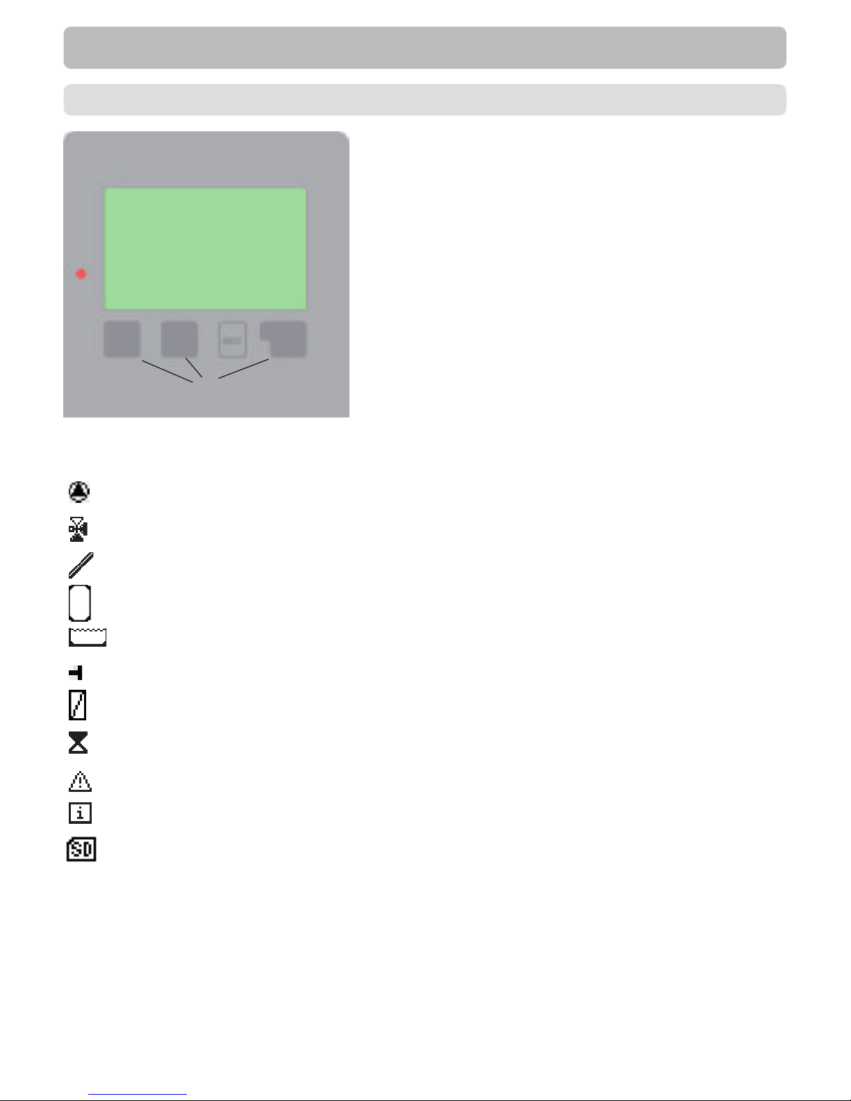
Examples of display symbols:
Pump (rotates in operation)
Valve (direction of ow in black)
Collector
Storage
Pool
Temperature sensor
Heat exchanger
Load pause (see Load time)
Warning / error message
New information available
Logging is active
More symbols can be found in the
chapter „Special functions“
(1)
(2)
(3)
(4)
The display (1), with its extensive text and graphics mode,
is almost self-explanatory, allowing easy operation of the
controller.
To change from the overview to the settings menu, press the
„esc“ key.
The green status LED (2) lights up when a relay is active, the
red LED blinks when an error occurs.
Inputs are made with 4 buttons (3+4), which functions change
context sensitive.
The „esc“ key (3) is always used to cancel or exit a menu.
If applicable there will be a request for conrmation as to
whether the changes which have been made should be
saved.
The function of each of the other three keys (4) is shown in
the display line directly above the keys; the right-hand key is
generally has a conrmation and selection function.
Examples of key functions:
+/- = enlarge/shrink values
▼/▲ = scroll menu down/up
yes/no = approve/reject
Info = additional information
Back = to previous screen
ok = conrm selection
Conrm = conrm setting
E.1. - Display and input
Page 18
18
Operation
E.2. - Commissioning help
takes you back step by step to the selection mode, thus cancelling the commissioning help. Finally, menu
„3.2. - Manual“ on page 21 should be used to test the switch outputs with the consumers connected, and
to check the sensor values for plausibility. Then switch on automatic mode.
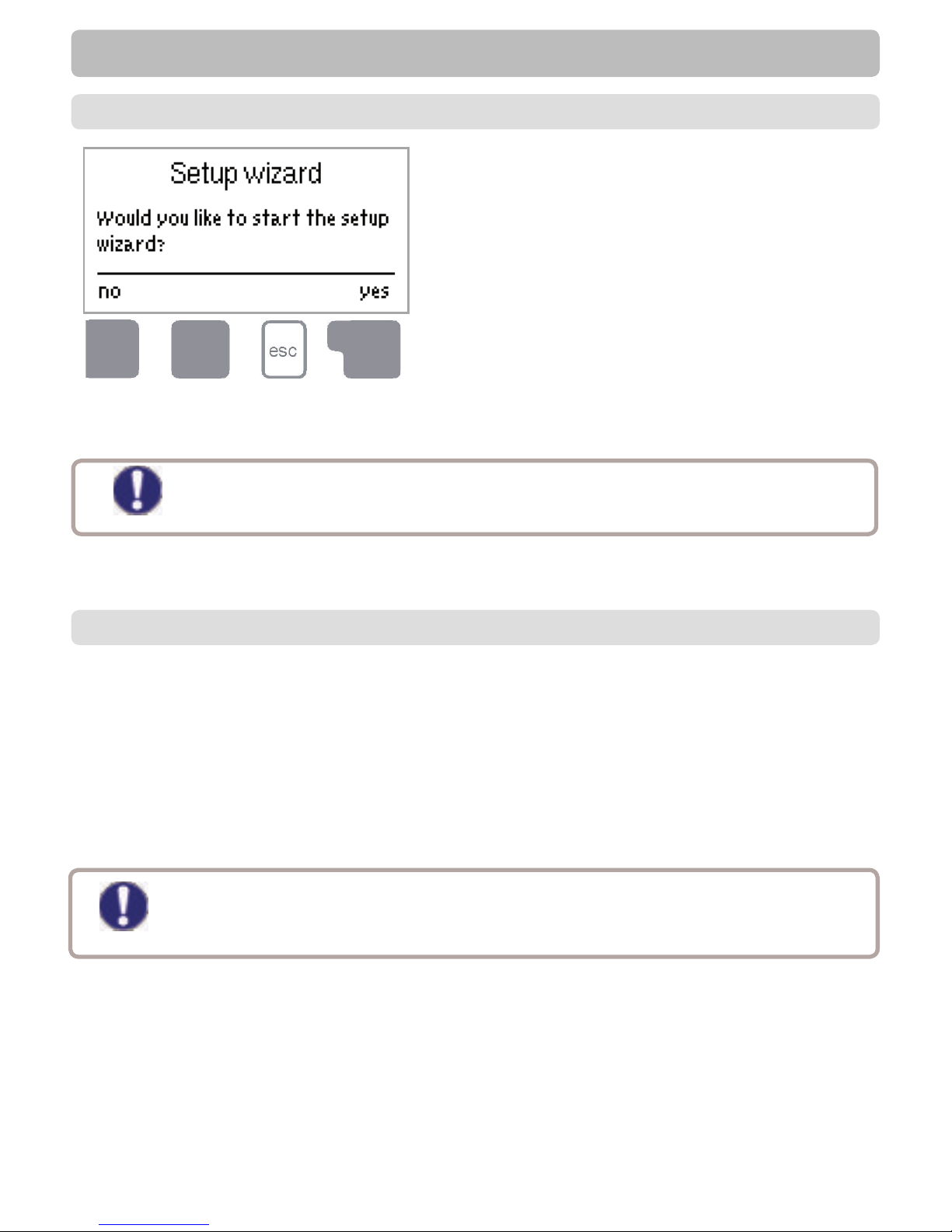
The rst time the controller is turned on and after the
language and time are set, a query appears as to
whether you want to parametrise the controller using the
commissioning help or not. The commissioning help can
also be terminated or called up again at any time in the
special functions menu. The commissioning help guides
you through the necessary basic settings in the correct
order, and provides brief descriptions of each parameter
in the display.
Pressing the “esc” key takes you back to the previous
value so you can look at the selected setting again or
adjust it if desired. Pressing the “esc“ more than once
Caution
Observe the explanations for the the individual parameters on the following pages, and
check whether further settings are necessary for your application.
E.3. - Free commissioning
If you decide not to use the commissioning help, you should make the necessary settings in the following
sequence:
- Menu 9. Language, page 45
- Menu 6.23 Time and Date, page 44
- Menu 6.1 Programm selection, page 26
- Menu 4. Settings, all values, page 22
- Menu 5. Protective functions, if necessary, page 24
- Menu 6. Special functions, if necessary, page 26
Finally, menu „3.2. - Manual“ on page 21 should be used to test the switch outputs with the consumers
connected, and to check the sensor values for plausibility. Then switch on automatic mode.
Caution
Observe the explanations for the the individual parameters on the following pages, and
check whether further settings are necessary for your application.
Page 19
19
Operation
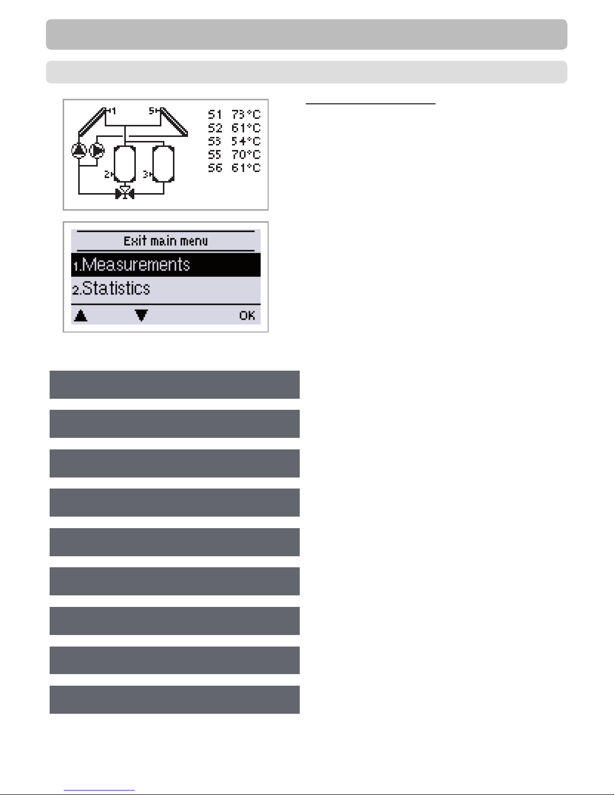
The graphics or overview mode appears when no key
has been press for 2 minutes, or when the main menu is
exited by pressing “esc“.
The up and down buttons are used to scroll through the
list of sensors and relays .
You can enter the Main menu by pressing the „esc“ key.
The following menus are available:
Current temperature values with explanations
Function control of the system with operating hours,
etc
Automatic mode, manual mode or switch unit off
Set parameters needed for normal operation
E.4. - Menu sequence and menu structure
Solar and frost protection, recooling, anti-seizing
protection
Program selection, sensor calibration, clock,
additional sensor, etc.
Against unintentional setting changes at critical
points
For diagnosis in the event of an error
Language selection
1. Measurements
2. Statistics
3. Operating mode
4. Settings
5. Protections
6. Special functions
7. Menu lock
8. Service Data
9. Language
Page 20
20
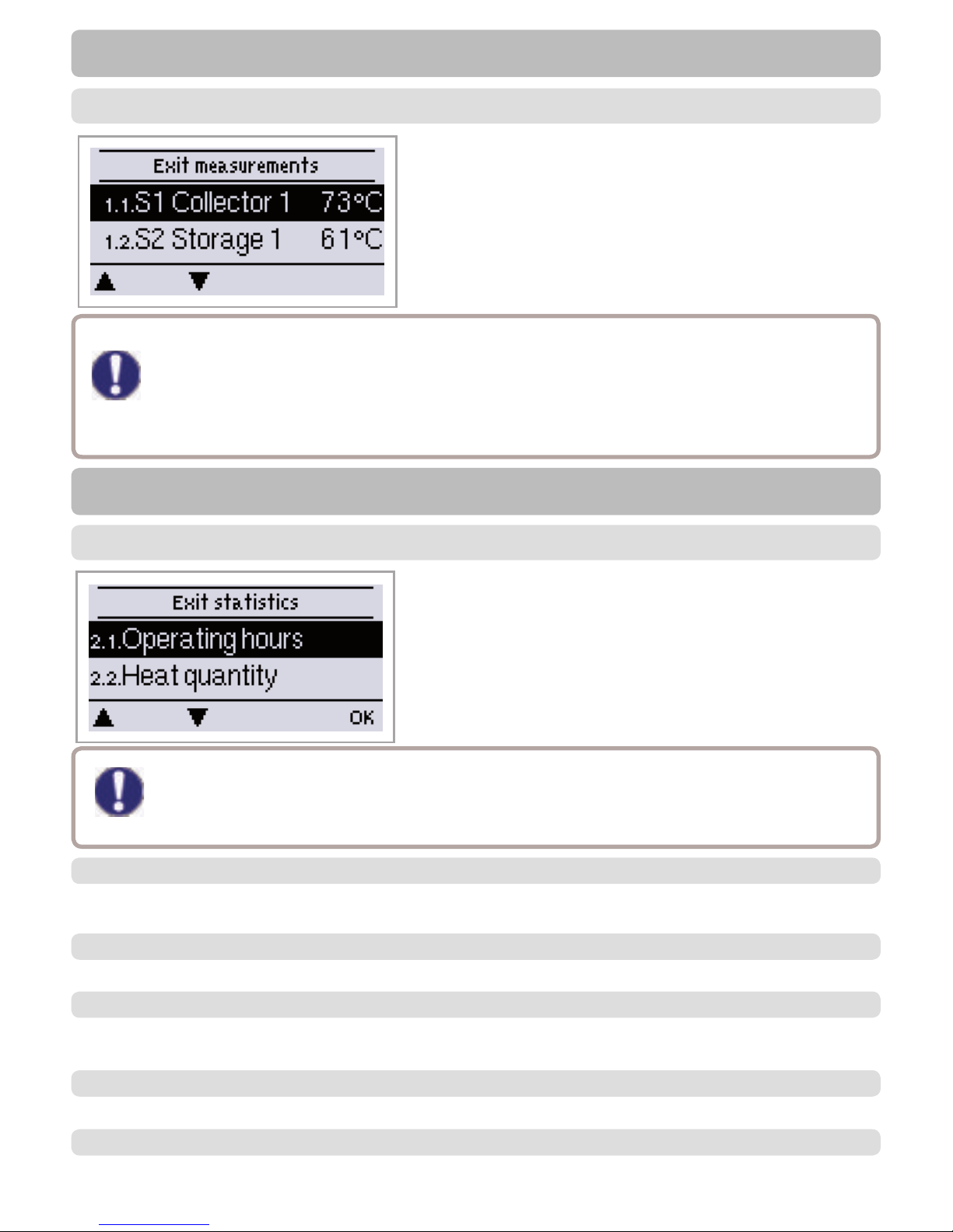
The menu “1. Measurement values” serves to display the
currently measured temperatures.
The menu is closed by pressing “esc” or selecting “Exit
measurement values”.
Selecting “Overview” or “esc” exits the Info mode.
Measurement values
1. - Measurement values
Caution
If “--” appears on the display instead of the measurement value, then there may be a defective
or incorrect temperature sensor. If the cables are too long or the sensors are not placed
optimally, the result may be small deviations in the measurement values. In this case the display
values can be compensated for by making entries on the controller. Follow the instructions
under „6.7. - Sensor calibration“ on page 43. What measurement values are displayed
depends on the selected program, the connected sensors and the speci c device design.
2. - Statistics
The menu “2. Statistics” is used for function control and long-
term monitoring of the system.
The menu is closed by pressing “esc” or selecting “Exit
statistics”.
Statistics
Caution
For analysis of the system data it is essential for the time to be set accurately on the controller.
Please note that the clock does not continue to run if the mains voltage is interrupted, and must
therefore be reset. Improper operation or an incorrect time may result in data being deleted,
recorded incorrectly or overwritten. The manufacturer accepts no liability for the recorded data!
2.1. - Operating hours
Display of operating hours of the solar pump connected to the controller; various time ranges (day-year) are
available.
2.2. - Heat output
Display of the heat output of the system. See also „6.5. - Heat quantity“ on page 41
2.3. - Graphic overview
This provides a clearly-organised display of the data listed under 2.1-2.2 as a bar graph. Various time
ranges are available for comparison. The two left-hand keys can be used to page through the data.
2.4. - Message log
Display of the last 20 events occurring in the system with indication of date and time.
Resetting and deleting the individual analyses. The function “All statistics” clears all analyses but not the
error messages.
2.5. - Reset/clear
Page 21
21
Operating modes
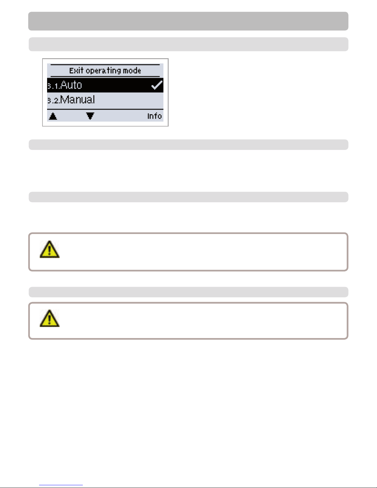
In menu “3. Operating modes” the controller can either
be placed in automatic mode, switched off, or placed in a
manual operating mode.
The menu is closed by pressing “esc” or selecting “Exit
operating modes”.
Automatic mode is the normal operating mode of the controller. Only automatic mode provides proper
controller function taking into account the current temperatures and the parameters that have been set!
After an interruption of the mains voltage the controller automatically returns to the last operating mode
selected!
3.1. - Automatic
3.2. - Manual
The relay and thus the connected consumer are switched on and off by pressing a key, with no regard to
the current temperatures and the parameters which have been set. The measured temperatures are also
shown to provide an overview and function control.
Danger
When operating mode “Manual” is activated, the current temperatures and the selected
parameters are no longer considered. There is a danger of scalding or serious damage to
the system. The operating mode “Manual” may only be used by specialists for brief function
tests or during commissioning!
3.3. - Off
When the operating mode “Off” is activated, all controller functions are switched off. This
can lead, for example, to overheating on the solar collector or other system components.
The measured temperatures are sstill displayed to provide an overview.
Caution
3. - Operating modes
Page 22
22
The following pages contain generally valid descriptions for the settings. Enumerations
may vary .
Caution
4. - Settings
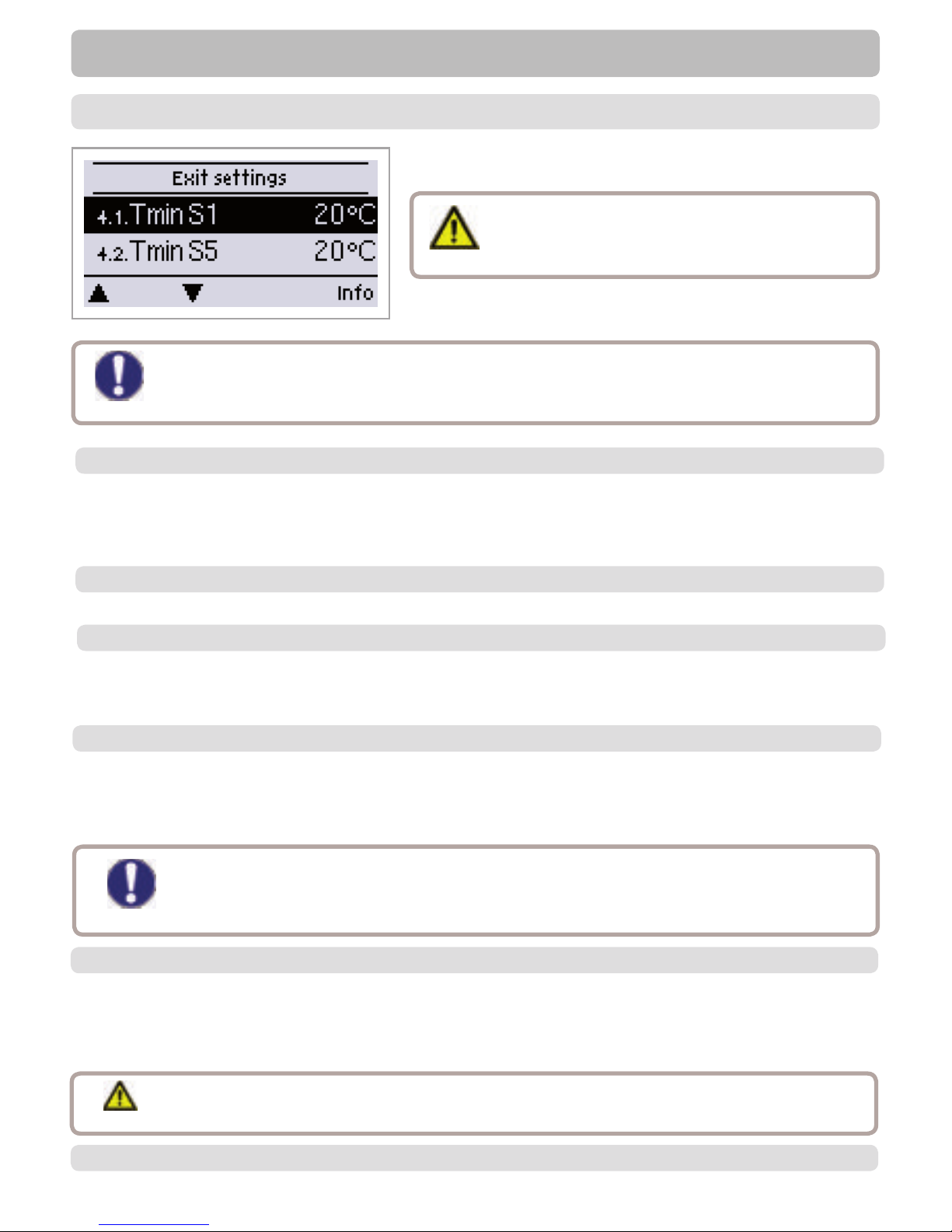
The necessary basic settings required for the control function
are made in menu “4. Settings”.
Caution
This does not under any circumstances replace
the safety facilities to be provided by the
customer!
The menu is closed by pressing “esc” or selecting “Exit
settings”.
Settings
4.1. - Tmin S (X)
Enable/start temperature at sensor X:
If this value is exceeded at the applicable sensor X and the other conditions are also met, then the
controller switches on the associated pump and/or valve. If the temperature at the sensor drops below this
value by 5°C, then the pump and/or the valve are switched off again.
4.2. - Tmin S5
4.4. - ∆ T Solar S (X)
If the set temperature difference is too small, this may result in ineffective operation,
depending on the system and sensor positions.Special switching conditions apply for speed
control (see „6.3. - Speed control R1 / R2“)!
Caution
Switch-on/switch-off temperature difference for sensor X :
If this temperature difference between the reference sensors is exceeded and the other conditions are also
met, then the controller switches the applicable relay on. When the temperature drops to ΔT Off, then the
relay is switched off.
Priority of Storages X
This determines the order, in which the storages are charged. If the same priority is set for 2 storages, the
charging is not switched over until charging the active storage is not possible anymore.
S. „4.1. - Tmin S (X)“
4.3. - Priority S (X)
4.5. - Tmax S (X)
4.6. - Priority S3
See „4.3. - Priority S (X)“
Switch-off temperature at sensor X
If this value is exceeded at the applicable sensor X, the controller switches the associated pump and/or
valve off. If the temperature falls below this value again and the other conditions are also met, then the
controller switches the pump and/or valve on again.
Temperature values that are set too high can lead to scalding or damage to the system.
Scalding protection must be provided by the customer!
Danger
Page 23
23
Settings
4.7. - ∆ T Solar S3
4.8. - Tmax S3
4.9. - Priority S4
4.10. - ∆ T Solar S4
4.11. - Tmax S4
4.12. - Tmax S3
See „4.5. - Tmax S (X)“
See „4.5. - Tmax S (X)“
See „4.5. - Tmax S (X)“
See „4.4. - ∆ T Solar S (X)“
See „4.4. - ∆ T Solar S (X)“
See „4.4. - Priority S (X)“
4.13. - Tmax SB
4.14. - Tmax SB WT
Danger
Switch-off temperature at heat exchanger sensor
If this value is exceeded at the applicable sensor, the controller switches the associated pump and/or valve
off. If the temperature falls below this value again and the other conditions are also met, then the controller
switches the pump and/or valve on again.
Temperature values that are set too high can lead to scalding or damage to the system.
Scalding protection must be provided by the customer!
Switch-off temperature at pool sensor. If this value is exceeded at the applicable sensor, the controller
switches the associated pump and/or valve off. If the temperature falls below this value again and the other
conditions are also met, then the controller switches the pump and/or valve on again.
Danger
Temperature values that are set too high can lead to scalding or damage to the system.
Scalding protection must be provided by the customer!
Temperature threshold for absolute priority
In systems with multiple storage tanks, charging of the lower-priority storage tank will never take place until
this set temperature setpoint at the storage tank sensor of the highest-priority storage tank is exceeded.
4.15. - T-priority
Interruption of charging into the lower priority storage tank
The charging of the lower-priority storage tank is interrupted after the settable time in order to check
whether the collector has reached a temperature level that allows charging in the higher-priority storage
tank. If so, the priority storage tank is charged. If not, the increase is measured (see „4.18. - Increase“), to
check if charging of the priority storage tank will be possible shortly.
4.16. - Loading time
Page 24
24
Settings
Extension of the charging pause due to temperature increase in the collector
For precise setting of the charging priorities for systems with multiple storage tanks, the necessary
temperature increase of the collector at which the interruption of the charging into the lower-priority storage
tank is extended by one minute is set here. The interruption is extended because the temperature increase
of the collector is expected to enable charging in the higher-priority storage tank soon.
As soon as ∆T conditions are met, the priority storage tank is charged. If the rise in temperature falls below
the set value, then the charging of the lower-priority storage tank is enabled again.
4.17. - Increase
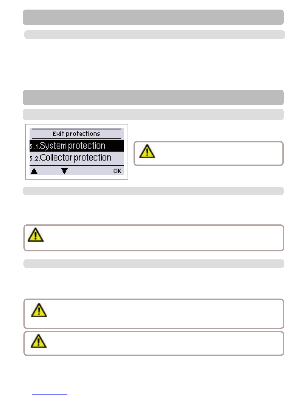
Menu „5. - Protections / Protective functions“ can be used to
activate and set various protective functions.
The menu is closed by pressing “esc” or selecting “Exit”.
Protections
5. - Protections / Protective functions
Caution
This does not under any circumstances replace the
safety facilities to be provided by the customer!
5.1. - System protection
Highest Priority Protection
System protection prevents overheating of system components by automatic shutdown of the solar pump.
If “SProt Ton” is exceeded for 1 minute at the collector, the pump is switched off and stays off. The pump is
activated again when the temperature drops below “SProt TOff”.
Caution
When system protection is on, the temperature in the idle collector will be very high, thus
the pressure in the system will rise and can damage your system. Pay close attention to the
instructions of the system manufacturer.
5.2. - Collector protection
Collector protection prevents overheating of the collector. The pump is switched on to transfer heat from
the collector to the storage tank. If “CP Ton” is exceeded at the collector sensor, the pump is switched on
until the temperature reaches “CP Toff” or the temperature “CP Tmax storage” is exceeded in the storage
or pool.
Danger
Danger
When collector protection is active, and both storage and pool are present, the storage is
heated up to „CP Storage S(x) Max“ beyond Tmax S2 (see „4.2. - Tmax S (X)“ on page 22)
which can result in scalding and system damage. When only a pool is used, the pool is not
used for collector protection.
System protection has a higher priority than collector protection. Even when the switch on
conditions for collector protection are present, the solar pump will be switched off when SP T on
is reached.
Page 25
25
Protective functions
In hydraulic systems with solar when the recooling function is activated excess energy from the storage tank is fed
back into the collector. This only takes place if the temperature in the storage tank is higher than the value “Recool
Tsetpoint” and the collector is at least 20°C cooler than the storage tank and before the storage tank temperature has
dropped below the value “Recool Tsetpoint”. In systems with two storage tanks the setting applies to both storage
tanks.
Recooling - Settings range: On, Off / Default setting: Off
Recooling Tref - Settings range: 0°C to 99°C / Default setting: 70°C
5.3. - Recooling
Caution
Energy is lost via the collector when Recooling is active! Recooling should only be active
in periods with very little demand for heat e.g. during longer absence / holidays.
Caution
This function causes energy to be lost via the collector! It is normally not activated for solar
systems with antifreeze.
Observe the operating instructions for the other system components!
A two-stage frost protection function can be activated. In stage 1 the controller switches the pump on for 1
minute every hour if the collector temperature drops below the set value “Frost stage 1”.
If the collector temperature drops further to the set value “Frost stage 2” the controller switches the pump on
continuously.
If the collector temperature then exceeds the value “Frost stage 2” by 2°C, then the pump switches off
again.
Frost protection setting range: on, off/default setting: off
Frost stage 1 setting range: from -25°C to 10°C or off/default setting: 7°C
Frost stage 2 setting range: from -25°C to 8°C/default setting: 5°C
5.4. - Frost Protection
If the seizing protection is activated, the controller switches the relay in question and the connected
consumer on every day at 12:00 (setting “daily”) or weekly on Sundays at 12:00 (setting “weekly”) for 5
seconds in order to prevent the pump and/or the valve from sticking after an extended stationary period.
Setting range R1: daily, weekly, off/default setting: Off
Setting range R2: daily, weekly, off/default setting: Off
Setting range R3: daily, weekly, off/default setting: Off
5.5. - Seizing protection
5.6. - Collector alarm
If this temperature is exceeded at the collector sensor when the solar pump is on a warning or error
message is triggered. A warning message is shown in the display.
Collector alarm - Settings range: On / Off / Default setting: Off
Collector Tmax - Settings range: 60 °C to 299 °C / Default setting: 115 °C
Delay settings range: 1 - 60 minutes / Default: 1 minute
Page 26
26
Special functions
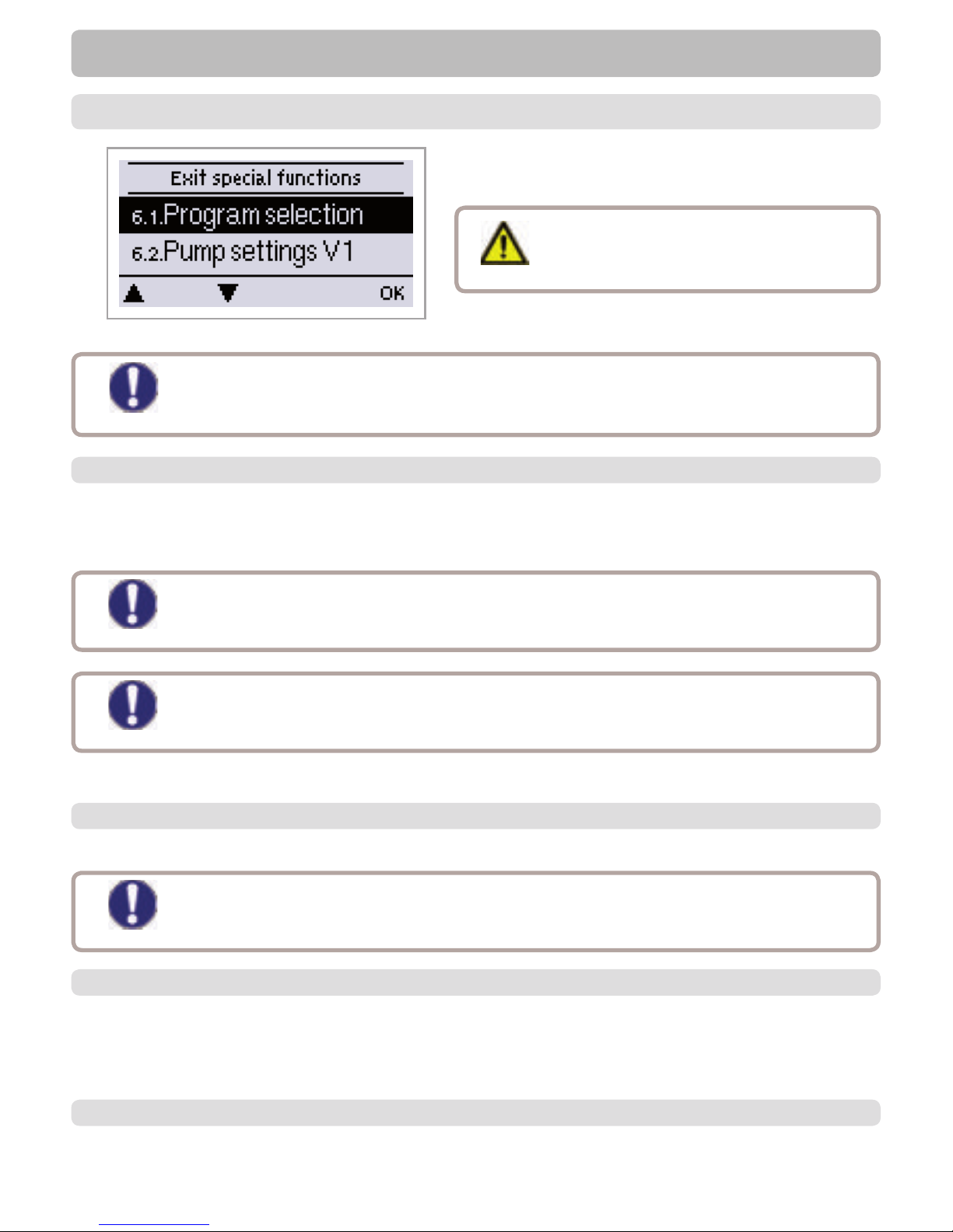
Menu “7. Special functions” is used to set basic items
and expanded functions.
The menu is closed by pressing “esc” or selecting “Exit
special functions”.
6. - Special functions
Caution
Other than the time all settings may only
be made by a specialist.
The suitable hydraulic variant for the speci c application is selected and set here (see „D.2. - Hydraulic
variants / systems“ on page 13). The associated diagram is displayed.
Settings range: 1-37 / Default setting: 1
6.1. - Program selection
Caution
Caution
Caution
Normally the program selection is made only once during initial commissioning by the
specialist. Incorrect program selection can lead to unpredictable errors.
The power supply of HE pumps with 0-10V / PWM pumps can be connected to the
corresponding relay (V1 -> R1, R2 -> V2), since the relays are switched on and off with the
signal.
If the program is changed, the settings revert to factory settings.
The enumeration of the menus may vary from system to system.
Caution
This menu contains the settings for 0-10V or PWM pump.
6.2. - Pump menu
6.2.1. - Type of pump
The type of speed controlled pump must be entered here.
Standard: Speed control for standard pumps.
0-10V: Speed control of e.g. High ef cency pumps by 0-10V signal.
PWM: Speed control of e.g. High ef cency pumps by PWM signal.
6.2.2. - Pump
In this menu, precon gured pro les for various pumps can be selected. Please note that individual settings
are still possible even when a pro le has been selected.
For manual settings, see „J. - Appendix“ on page 49
Page 27
27
Special functions
With speed control the LTDC makes it possible to vary the speed of connected pumps.
6.3. - Speed control R1 / R2
6.3.1. - Modes
The following speed modes are available here:
Off: There is no speed control. The connected pump is only switched on or off with full speed.
Mode M1: After the purging time the controller switches to the set max. speed. If the temperature
difference ∆T between the reference sensors (collector and storage tank) is less than the set value, then
the speed is decreased by one stage after the control time elapses. If the temperature difference between
the reference sensors is greater than the set value, then the speed is increased by one stage after the
control time elapses. If the controller has adjusted the speed of the pump down to the smallest stage and
the ∆T between the reference sensors is ∆T off, the pump is switched off.
Mode M2: After the purging time the controller switches to the set min. speed. If the temperature
difference ∆T between the reference sensors (collector and storage tank) is greater than the set value,
then the speed is increased by one stage after the control time elapses. If the temperature difference ∆T
between the reference sensors is below the set value, then the speed is decreased by one stage after the
control time elapses. If the controller has adjusted the speed of the pump down to the smallest stage and
the ∆T between the reference sensors is T∆off, the pump is switched off.
Mode M3: After the purging time the controller switches to the set min. speed. If the temperature at the
reference sensor (collector) is greater than the setpoint to be set subsequently, then the speed is increased
by one stage after the control time expires. If the temperature at the reference sensor (collector) is less
than the setpoint to be set subsequently, then the speed is decreased by one stage after the control time
expires.
Mode M4:
When the primary storage is loaded, speed control works as in M3.
When the secondary storage is loaded, speed control works as in M2.
Settings range: M1,M2,M3, M4, Off / Default: Off
This function should only be activated by a specialist. Depending on the pump and pump
stage used, the minimum speed should not be set too low, because otherwise the pump or
the system may be damaged. The information provided by the relevant manufacturer must
also be observed! If in doubt, the min. speed and the pump stage should generally be set to
high rather than too low.
Caution
6.3.2. - Purging time
During this time period, the pump is running with full speed (100%) to ensure trouble-free startup. After this
time has passed, the pump is set to speed control and is set to max. speed or min speed, depending on the
speed control variant „6.3.1. - Modes“ on page 27 chosen.
Settings range: 5 to 600 seconds / Default setting: 8 seconds
6.3.3. - Sweep time
Sweep time determines the inertia of the speed control to prevent strong uctuations in temperature.
Sweep time is the timespan for a complete change from minimum to maximum pump speed.
Settings range: 1 to 15 minutes / Default setting: 4 minutes
Page 28
28
Special functions
Caution
Caution
The indicated percentages are guide values that may vary to a greater or lesser extent
depending on the system, pump and pump stage.
The indicated percentages are guide values that may vary to a greater or lesser extent
depending on the system, pump and pump stage.. 100% is the maximum possible voltage/
frequency of the controller.
6.3.4. - max. speed
6.3.5. - min. speed
6.3.6. - Setpoint
The maximum speed of the pump is speci ed here. During the setting the pump runs at the speci ed speed
and the ow rate can be determined.
Settings range: 70% to 100% / Default setting: 100%
The minimum speed of the pump at relay R1 is speci ed here. During the setting the pump runs at the
speci ed speed and the ow rate can be determined.
Settings range: (Speed from „J.14.6. - Speed when „On““ on page 49) to max. speed -5% / Default
setting: 30%
This value is the control setpoint for Mode 3 (see „6.3.1. - Modes“ on page 27). If the value at the
collector sensor drops below this, the speed is reduced. If it rises above this, the speed is increased.
Settings range: 0° to 90°C / Default setting: 60°C
Page 29
29
Relay functions
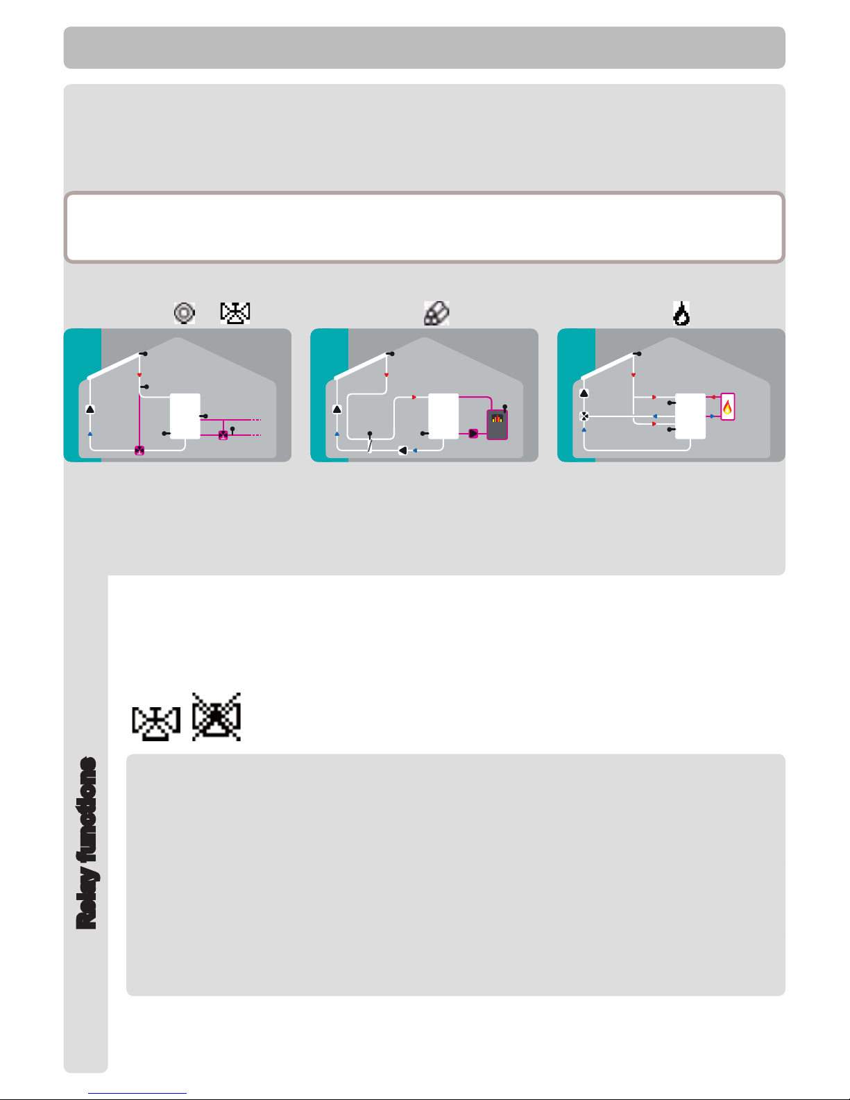
The enumeration does not correspond to the controllers menu enumeration.
6.6.1. - Solar bypass
Use the relay to switch a bypass valve or a bypass pump
This can direct the ow pass the storage, when the ow temperature at the bypass sensor is lower
than the storage that has to be charged.
Settings range: On; Off
6.6.1.1. - Variant
6.6.1.2. - Bypass (sensor)
This menu determines wether a pump or valve is used to direct the ow through the bypass.
Settings range: Pump, Valve / Default setting: Valve
The ow sensor for the bypass function is selected in this menu. Do not install in the return ow.
Settings range: S1-S8, VFS1, VFS2 / Default setting: none
Special functions
Examples:
System 1 +
+
System 14 + System 11 +
Solar with storage
with additional functions Solar
Bypass
and Return Flow Increasee
Solar with heat exchanger
with additional function Solid Fuel
Boiler
Solar with 2 zone storage and
switching valve
with additional function Thermostat
6.6. - Relay functions
The here explained additional functions can be assigned to unused relays. Every additional function can
only be used once. Pay special attention to the technical data of the relays
(„B.1. - Specications“ on page 6).
Page 30
30
6.6.2. - Thermostat
Thermostat is used for time- and temperature controlled additional heating.
Settings range: On, Off, Inverted
6.6.2.1. - TH Set
Taget temperature at thermostat sensor 1. Below this temperature, additional heating is switched
on, till TH set + hysteresis is reached.
Settings range: 0-100°C / Default setting: 50
6.6.2.2. - TH hysteresis
Hysteresis of setpoint temperature.
Settings range: -20 to +20K / Default setting: 10K
Temperature values which are set too high can lead to scalding or damage to the
system. Scalding protection must be provided by the customer!
Danger!
Caution
In Energy savings mode, different settings may apply, see e.g. T eco.
6.6.2.3. - Thermostat sensor 1
T set is measured with thermostat sensor 1.
When thermostat sensor 2 is connected, the relay switches on when T set is undershot at
thermostat Sensor 1, and switches off when T set + hysteresis at thermostat sensor 2 is
exceeded.
Settings range: S1-S8, VFS1-2, active storage / Default setting: none
6.6.2.4. - Thermostat sensor 2
Optional switch off sensor
When T set + hysteresis is exceeded at the optional thermostat sensor 2, the relay is switched off.
Settings range: S1-S8, VFS1-2, active storage / Default setting: none
6.6.2.5. - T eco
For Energy saving mode
When Energy saving mode is active: During solar charge T eco is used instead of TH set. When
the temperature drops below T eco at thermostat sensor 1, the relay is switched on and heats up
to T eco + hysteresis.
Settings range: 0-100°C / Default setting: 40°C
Special functions
Relay functions
For Energy saving mode
Loading this storage activates the Energy saving mode
When this storage is charge by solar, additional heating is only switched on when the temperature
is below T eco.
Settings range: (Storage sensors) / Default setting: fi rst storage
6.6.2.6. - Storage
Page 31
31
Special functions
Relay functions
Thermostat is used for time- and temperature controlled additional heating.
See Thermostat 1
6.6.2.7. - Energy saving mode
Energy saving mode switches the heating on when T eco is undershot und heats up to T eco +
hysteresis when solar charge is active.
Settings range: On, Off / Default setting: Off
6.6.2.8. - Periods
Thermostat activity times
Set the desired periods of time when the thermostat should be active. 3 periods can be set per
day, settings can also be copied to other days. Outside the set times the thermostat is switched
off.
Setting range: from 00:00 to 23:59 /default setting: 06:00 to 22:00
6.6.3. - Thermostat 2
Page 32
32
Special functions
Relay functions
6.6.4. - Cooling
This is used to cool down e.g. storages to a setpoint temperature by radiating heat.
Settings range: S1-S8, VFS1-2, active Storage / Default setting: None
6.6.4.1. - Co T set
Target temperature at thermostat sensor 1. Cooling is on above this temperature till Co T set +
hysteresis is reached.
Settings range: 0-100°C / Default setting: 50°C
6.6.4.2. - Co hysteresis
If the temperature at th drops below Co T set + hysteresis, the relay is switched off.
Settings range: 0-100 / Default setting: 40
6.6.4.3. - Cooling (sensor)
Reference sensor of the cooling function.
Settings range: (Storage sensor) / Default setting: First storage
6.6.4.4. - Periods
Cooling activity times
Set the desired periods of time when the cooling should be active. 3 periods can be set per day,
settings can also be copied to other days. Outside the set times the cooling function is switched
off.
Setting range: from 00:00 to 23:59 /default setting: 06:00 to 22:00
Page 33
33
6.6.5. - Return flow increase
This function is used to raise the temperature of e.g. the return ow by the storage.
Settings range: On, Off
6.6.5.1. - RF Tmax
Maximum temperature at the return ow sensor. If this temperature is exceeded, the relay is
switched off.
Settings range: 0-80°C / Default setting: 70°C
6.6.5.2. - ∆T return flow
Switch-on temperature difference:
When this difference is exceeded between return ow sensor and storage sensor, the relay is
switched on.
Settings range: 5-20 K / Default setting: 8 K
Switch-off temperature difference:
When this difference is exceeded between return ow sensor and storage sensor, the relay is
switched off.
Settings range: 2-19 K (limited by ∆T Storage RF On) / Default setting: 4 K
6.6.5.3. - Return flow (sensor)
Determines the sensor for return ow increase.
Settings range: S1-S8, VFS1-2, active Storage / Default setting: none
6.6.5.4. - Storage (sensor)
Determines the storage sensor
Settings range: S1-S8, VFS1-2, active Storage / Default setting: none
Special functions
Relay functions
Page 34
34
Special functions
6.6.6. - Collector fi eld cooling
This function controls an external coolig unit to cool down the collector.
Settings range: On, Off
6.6.6.1. - Tmax fi eld
If this temperature is exceeded at the reference sensor, the relay is switched on.
Settings range: 100 °C to 180 °C / Default: 120 °C
6.6.6.2. - Hys min
When the temperature falls below Tmax eld +Hys min, the relay is switched off.
Settings range: -20 to -2°C / Default: -5
6.6.6.3. - Hys max
To protect the cooling unit itself from damage, the relay is switched off as soon as the temperature
at the reference sensor reaches Tmax eld + Hys max
Settings range: 2 to 60 °C / Default: 20
6.6.6.4. - Field cooling sensor
Reference sensor of the collector eld cooling function.
Settings range: S1-S8, VFS1-2, active storage, RC / Default: none
This function does not activate the solar pump to cool the collector. Therefore,
please refer to the collector protection.
Caution
Relay functions
Page 35
35
6.6.7. - Anti Legionella
6.6.7.1. - AL T set
6.6.7.2. - AL residence time
This function is used to heat up the system during selected periods to eliminate legionella bacteria.
Settings range: S1-S8, VFS1-2, Active storage/ Default setting: none
This temperature has to be detected for the time set in AL residence time at the AL sensors for a
successful heat up.
Settings range: 60-99 °C / Default setting: 70°C
This determines the time span for which the AL T set temperature must be detected for a
successfull AL heat up.
Settings range: 1-120 min / Default setting: 60 min
Special functions
Caution
The anti-Legionella function is switched off at delivery.
Whenever heating-up has been carried out with the anti-Legionella function switched
on, an information message with the date appears on the display.
During the anti-Legionella function the storage tank is heated up over the set value
“Tmax S(X)”, which can lead to scalding and damage to the system.
Danger
This anti-Legionella function does not provide complete protection against
Legionella, because the controller is dependent on suf cient energy being fed
in, and it is not possible to monitor the temperatures in the entire range of the
storage tanks and the connected piping system. To provide complete protection
against Legionella bacteria, it must be ensured that the temperature is raised to the
necessary temperature, and at the same time there must be water circulation in the
storage tank and piping system by means of other additional energy sources and
external control units.
Caution
6.6.7.3. - Last AL heat
6.6.7.4. - AL sensor 1
This displays the date and time of the last successful heat up.
No settings
This temperature is used to measure the AL temperature.
Settings range: S1-S8, VFS1-2, Active storage/ Default setting: none
6.6.7.5. - AL Sensor 2
Optional AL sensor
When a second sensor is connected, both sensors must reach and hold the setpoint temperature
for the residence time for a successful heat up.
Settings range: S1-S8, VFS1-2, Active storage/ Default setting: none
6.6.7.6. - AL-times
During this periods the AL heat up is attempted.
Setting range: from 00:00 to 23:59 / default setting: 06:00 to 22:00
Relay functions
Page 36
36
6.6.8. - Heat transfer
This is used to transfer energy from one storage to another with a pump.
Settings range: S1-S8, VFS1-2, Active storage/ Default setting: none
6.6.8.1. - ∆ T Heat transfer
Temperature difference for heat transfer function.
When the temperature difference between HT Source and HT Drain reaches ∆T Heat Transfer
On, the relay is switched on. As sson as the difference drops to ∆T Heat Transfer Off, the relay is
switched off again.
On: Settings range: 5-20 K/ Default setting: 8 K
Off: Settings range: 2 K to ∆T Ein / Default setting: 4 K
Special functions
6.6.8.2. - Setpoint
Setpointtemperature of the target storage
When this temperature is detected in the target storage, heat transfer is switched off.
Settings range: 0-90 °C / Default setting: 60°C
6.6.8.3. - HT Tmin
Minimum temperature in source storage to enable the heat transfer
Settings range: 0-90 °C / Default setting: 30°C
6.6.8.4. - HT Source (sensor)
This menu determines the sensor, that is placed in the source storage.
Settings range: S1-S8, VFS1-2, Active storage/ Default setting: none
6.6.8.5. - HT Drain (Target sensor)
This determines the sensor placed in the storage that is receiving energy from the source storage.
Settings range: S1-S8, VFS1-2, Active storage/ Default setting: none
Relay functions
Page 37
37
Special functions
6.6.9. - Difference
6.6.9.1. - ∆ T difference
6.6.9.2. - DF source (sensor)
The relay is switched on when a specic temperature difference (∆ T) is reached.
Settings range: On, Off
Switch on - difference:
When this temperature difference is reached, the relay is switched on.
Settings range: 5-20° C / Default setting: 8° C
Switch off - difference:
When this temperature difference is reached, the relay is switched off.
Settings range: 2-19° C / Default setting: 4° C (the upper limit is the switch on - difference)
Heat source sensor for Difference function
This determines the sensor for the heat source.
Settings range: S1-S8, VFS1-2, Active storage/ Default setting: none
6.6.9.3. - Diff Tmin
Minimum temperature at source sensor to enable the difference relay
When the temperature at the source sensor is below this level, the difference function is disabled.
Settings range: 0 to 90°C / Default setting: 20°C
6.6.9.4. - DF Drain (sensor)
6.6.9.5. - DF Tmax
Drain sensor / Target sensor for difference function
This determines the sensor for the target storage.
Settings range: S1-S8, VFS1-2, Active storage/ Default setting: none
Maximum temperature at target sensor to enable difference function
If the temperature at the target sensor exceeds this value, difference function is disabled.
Settings range: 0 to 99°C / Default setting: 60°C
Relay functions
Page 38
38
6.6.10. - Solid fuel boiler
The relay is used to control an additional solid fuel boiler.
Settings range: On, Off
Special functions
Relay functions
6.6.10.1. - SF Tmin
Minimum temperature in the solid fuel boiler to switch on the pump. If the temperature at the boiler
sensor is below this temperature, the relay is disabled.
Settings range: 0 ° C to 100° C / Default setting: 70° C
6.6.10.2. - ∆ T Solid fuel
Switch on and Switch off condition for the temperature difference between boiler and storage.
Switch on difference ∆ T SF
Settings range: 5 to 20 K / Default setting: 8
Switch off temperature difference ∆ T SF
Settings range: 0 K to Switch ∆ T SF / Default setting: 7
6.6.10.3. - SF Tmax
Maximum temperature in the storage. If this is exceeded, the relay is switched off.
Settings range: Off to 100°C / Default setting: 70° C
This determines the sensor, that is used as boiler sensor.
Settings range: S1-S8, VFS1-2, Active storage/ Default setting: none
6.6.10.4. - Boiler sensor
This determines the sensor, that is used as storage sensor.
Settings range: S1-S8, VFS1-2, Active storage/ Default setting: none
6.6.10.5. - Storage sensor
6.6.11. - Error message
The relay is switched on, when one or more protective funtion is active or a message is shown.
This function can be inverted, so that the relay is alway on and switches off when a protective
function or a message is shown.
Settings range: On, Inverted, Off / Default setting: Off
Collector protection
System protection
Frost protection
Recooling
Antilegionella protection
Message
Collector alarm
Page 39
39
6.6.12. - Pressure monitor
6.6.12.1. - Pressure monitor
The relay is switched on when the pressure drops below set minimum or exceeds the set
maximum pressure.
Settings range: On, Off / Default setting: Off
This menu is used to congure the system pressure montoring via direct sensor. As soon as the
set limits are exceeded, the relay is switched on.
6.6.12.2. - RPS1 / RPS2
Type of pressure sensor
This menu is used to determine the type of pressure sensor used.
Please note: If e.g. VFS1 is connected, RPS1 option is not shown.
Settings range: Off; 0-0,6 bar; 0-1 bar; 0-1,6 bar; 0-2,5 bar; 0-4 bar; 0-6 bar; 0-10 bar
Default setting: Off
6.6.12.3. - Pmin
Minimum pressure. If this value is undershot, an error message is displayed and the relay is
switched on.
Settings range: Off; 0,0 to 1,6 bar
Default setting:
6.6.12.4. - Pmax
Maximum pressure. If this value is exceeded, an error message is displayed and the relay is
switched on.
Settings range: Off; 0,0 to 10 bar
Default setting: 1,6 bar
Special functions
Relay functions
6.6.13. - Booster pump
6.6.13.1. - Filling time
Additional pump that lls the system at the start of every solar charge.
Settings range: S1-S8, VFS1-2, Active storage/ Default setting: none
Time the pump is switched on
This setting determines the length of time the pump is switched on at the start of a solar charge.
Settings range: 0-120 seconds / Default setting: 30 seconds
Page 40
40
6.6.15. - Always on
Relay is always switched on.
6.6.16. - Heating circuit
Heat circuit pump is controlled with a xed hysteresis of (+/-1° for setpoint temperature).
30 seconds Switch on and Switch off delay is xed setting to prevent unnecessary switching of the
pump.
RC21 room controller can be used as room temperature sensor.
Settings range: On, Off
6.6.16.1. - Room set day
Room reference temperature in day mode. If this temperature is exceeded at the room
temperature sensor at the set times, the relay is switched off.
Settings range: 10 to 30° C
6.6.16.2. - Room set night
Room reference temperature in night mode. If this temperature is exceeded at the room
temperature sensor at the set times, the relay is switched off.
Settings range: 10 to 30° C
Special functions
Relay functions
6.6.16.3. - Room sensor
This menu determines the sensor for the room temperature.
Settings range: S2 to S7, RC
6.6.16.4. - Periods
Set the desired periods of time when the heat circuit day mode should be active. 3 periods can be
set per day, settings can also be copied to other days. Outside the set times the heating function is
working in night mode.
Setting range: from 00:00 to 23:59 /default setting: 06:00 to 22:00
6.6.14. - Parallel operation R (X)
The relay is switched on at the same time as the set relay R1 or R2.
Settings range: On, Off, Inverted
6.6.14.1. - Delay
This menu determines how long after the start of R1 or R2 the parallel relay is switched on.
Settings range: 0-120 seconds / Default setting: 30 seconds
6.6.14.2. - Followup time
This menu determines how long after the switch off of R1 or R2 the parallel relay is switched off.
Settings range: 0-120 seconds / Default setting: 30 seconds
Page 41
41
Special functions
6.9. - Heat quantity
6.9.1. - Constant fl ow
When the heat meter mode „Flow rate“ is selected, an approximated heat quantity is calculated using the
values the user has to enter. These are type of glycol/AntiFreeze, glycol portion and ow rate. These values
are put into correlation with the temperature data of collector sensor and storage sensor. If necessary a
correction value for ΔT can be set: Since for the heat meter the collector and the storage temperature are
used, a difference to the ow respectively return ow temperature can be compensated by changing Offset
ΔT accordingly.
Example:
Displayed collector temp. 40°C, measured ow temperature 39°C, displayed storage temperature 30°C,
measured return temperature 31°C = results in a correction value of -20% (displayed ΔT 10K, real ΔT 8K =
-20% correction)
Caution
The heat quantity measured in the mode “Flow rate” is a calculated approximation for
function control of the system.
6.9.1.1. - Flow sensor (X)
This determines the sensor that is used to measure the ow temperature.
Settings range: S1-S8, VFS1-2, active collector, active storage/ Default setting: S1
6.9.1.2. - Return sensor
This determines the sensor that is used to measure the return temperature.
Settings range: S1-S8, VFS1-2, Aktiver Collector, Active storage/ Default setting: S2
6.9.1.3. - Anti freeze type
Set the type of anti freeze used. If none is used, please set to 0.
Settings range: Ethylen, Propylen / Default setting: Propylen
6.9.1.4. - Glycole percentage
The amount of anti freeze agent in the system.
Settings range: 0-100% / Default setting: 45%
6.9.1.5. - Flow rate (X)
Flow rate that is used to calculate the heat quantity
This determines the ow rate in litres per minute that is used for the calcualtion of the heat quantity.
Settings range: 0-100 l/min / Default setting: 5 l/min
6.9.1.6. - Offset ∆ T
Correction value for temperature difference
Since for the heat meter the collector and the storage temperature are used, a difference to the ow
respectively return ow temperature can be compensated by changing Offset ΔT accordingly.
Example:
Displayed collector temp. 40°C, measured ow temperature 39°C, displayed storage temperature 30°C,
measured return temperature 31°C = results in a correction value of -20% (displayed ΔT 10K, real ΔT 8K =
-20% correction)
Settings range: -50 to +50% / Default setting: 0%
Page 42
42
Special functions
6.9.2. - VFS (X)
Select a VFS sensor for ow measurement.
6.9.2.1. - VFS Typ
The VFS type is set here.
Settings range: Off; 1-12; 1-20; 2-40; 5-100; 10-200; 20-400 / Default setting: Off
6.9.2.2. - VFS - Position
This setting determines the position of the VFS sensor.
Settings range: ow, return / Default setting: return
6.9.2.3. - Reference sensor
The reference sensor used for the heat metering is set here.
Settings range: S1-S8, VFS1-2, active collector, active storage/ Default setting: S6
Caution
To prevent damage to the Vortex Flow Sensor it is strongly recommended to install it into the
return ow. If it is necessary to install in the ow, it is imperative not to exceed the maximum
temperatures of the sensor! (0° C to 100°C and -25°C to 120°C short term)
6.10. - Pressure monitor
6.10.1. - Pressure monitor
6.10.1.1. - RPS1 / RPS2
6.10.1.2. - Pmin
6.10.1.3. - Pmax
A message is shown when the pressure drops below set minimum or exceeds the set maximum pressure.
No relay is switched, for that see „6.4.12. - Pressure monitor“ on page 39.
Maximum pressure.
If this value is exceeded, an error message is displayed and the relay is switched on.
Settings range: Off; 0,0 to 10 bar
Default setting: Maximumvalue of the sensor
Minimum pressure.
If this value is undershot, an error message is displayed and the relay is switched on.
Settings range: Off; 0,0 to 1.6 bar
Default setting: 0,0
Type of pressure sensor
This menu is used to determine the type of pressure sensor used.
Please note: If e.g. VFS1 is connected, RPS1 option is not shown.
Settings range: Off; 0-0.6 bar; 0-1 bar; 0-1.6 bar; 0-2.5 bar; 0-4 bar; 0-6 bar; 0-10 bar
Default setting: Off
A message is shown and the LED ashes when the pressure deviates from the set minimum or maximum
value.
Settings range: On, Off / Default setting: Off
Page 43
43
6.11. - Sensor calibration
Caution
Caution
Settings sind nur in Sonderfällen bei Erstinbetriebnahme durch den Fachmann nötig.
Falsche Messwerte können zu Fehlfunktionen führen.
Starting the commissioning help guides you in the correct order through the basic settings necessary for
commissioning, and provides brief descriptions of each parameter in the display.
Pressing the “esc” key takes you back to the previous value so you can look at the selected setting again
or adjust it if desired. Pressing the “esc” more than once takes you back to the selection mode, thus
cancelling the commissioning help.
6.12. - Commissioning
May only be started by a specialist during commissioning! Observe the explanations for
the the individual parameters in these instructions, and check whether further settings are
necessary for your application.
Deviations in the temperature values displayed, for example due to cables which are to long or sensors
which are not positioned optimally, can be compensated for manually here. The settings can be made for
each individual sensor in steps of 0.8°C (temperature) resp. 0.2% of the measuring range of the VFS / RPS
sensor ( ow rate / pressure) per step.
Offset Sensor Settings range: -100 ... +100 / Default setting: 0
Caution
All of the settings that have been made can be reset, thus returning the controller to its delivery state.
6.13. - Factory settings
The entire parametrisation, analyses, etc. of the controller will be lost irrevocably. The
controller must then be commissioned once again.
Special functions
With some solar systems, especially with vacuum tube collectors, it may occur that the measurement value
acquisition at the collector sensor occurs too slowly or too inaccurately because the sensor is often not at
the hottest location. When the start help is activated the following sequence is carried out:
If the temperature at the collector sensor increases by the value speci ed under “Increase” within one
minute, then the solar pump is switched on for the set “Purging time” so that the medium to be measured
can be moved to the collector sensor. If this still does not result in a normal switch-on condition, then the
start help function is subject to a 5-minute lockout time.
Start help setting range: on, off/default setting: off
Purging time setting range: 2 ... 30 sec./default setting: 5 sec.
Increase setting range: 1 °C. . ..10°C/default se tting: 3°C/min .
6.14. - Start aid function
Caution
This function should only be activated by a specialist if problems arise with acquisition of
measurement values. In particular follow the instructions from the collector manufacturer.
Page 44
44
Caution
This menu is used to set the current time and date.
When this function is active, the controller’s clock changes automatically to and from DST (DST, Daylight
Savings Time).
6.15. - Time and date
6.16. - Daylight saving time
For analysis of the system data it is essential for the time to be set accurately on the
controller. Please note that the clock does not continue to run if the mains voltage is
interrupted, and must therefore be reset.
When active, the displays backlight is switched off after 2 minutes of inactivity.
6.17. - Sleep mode
Caution
If a message is waiting, the backlight is not switched off.
This menu is used to select the temperature unit that is displayed.
6.18. - Temperature unit
Special functions
6.19. - Network
6.19.1. - Access Control
6.19.2. - Ethernet
In this menu, the settings of the Ethernet connection of the data logger are set.
Activate oder deactivate the ethernetfunction.
6.19.2.1. - Ethernet
6.19.2.2. - MAC Adress
6.19.2.3. - Auto-Confi guration (DHCP)
6.19.2.4. - IP-Adress
6.19.2.5. - Subnetz
6.19.2.6. - Gateway
6.19.2.7. - DNS-Server
In this menu, the settings of the ethernet connection of the data logger can be set.
Displays the individual MAC address of the data logger.
In this menu, the IP of the gateway for the data logger can be set.
In this menu, the IP address of the data logger can be set.
In this menu you can add or remove four users who should have access to the data logger. ITo add a user in
the list, select <add user>. The list show you the last 5 users that tried to connect to the data logger. Select a
user with OK to give it to grant access. To revoke access again choose one of the 4 users from your list and
choose <remove user>.
If activated, the datalogger requests IP adresses and network parameters from a DHCP server.
In this menu the subnet mask of the data logger can be set.
In this menu, the IP address of the DNS server can be set.
Page 45
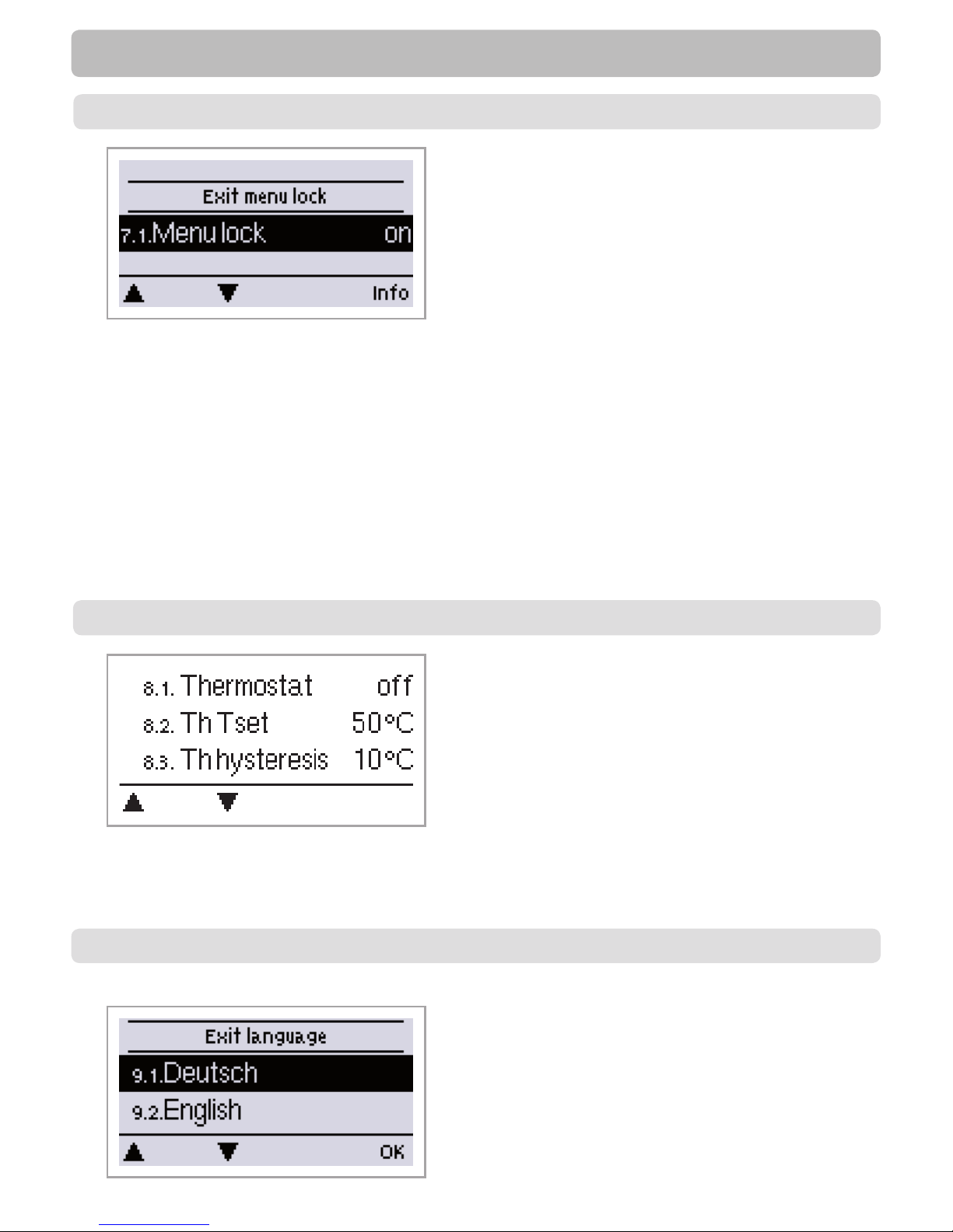
45
The menus listed below remain completely accessible despite the menu lock being activated, and can be
used to make adjustments if necessary:
1. Measurement values
2. Statistics
6.23. Time&date
7. Menu lock
8. Service values
To lock the other menus, select “Menu lock on”.
To enable the menus again, select “Menu lock off”.
Setting range: on, off/default setting: off
Menu lock, Service values, languages
Menu “7. Menu lock” can be used to secure the
controller against unintentional changing of the
set values.
The menu is closed by pressing “esc” or selecting
“Exit menu lock”.
7. - Menu lock
The menu „8. - Ser vice values“ can be used for remote
diagnosis by a specialist or the manufacturer in the event of
an error, etc.
8. - Service values
9. - Languages
Menu “9. Language” can be used to select the
language for the menu guidance. This is queried
automatically during initial commissioning.
The choice of languages may differ, however,
depending on the device design.
Page 46
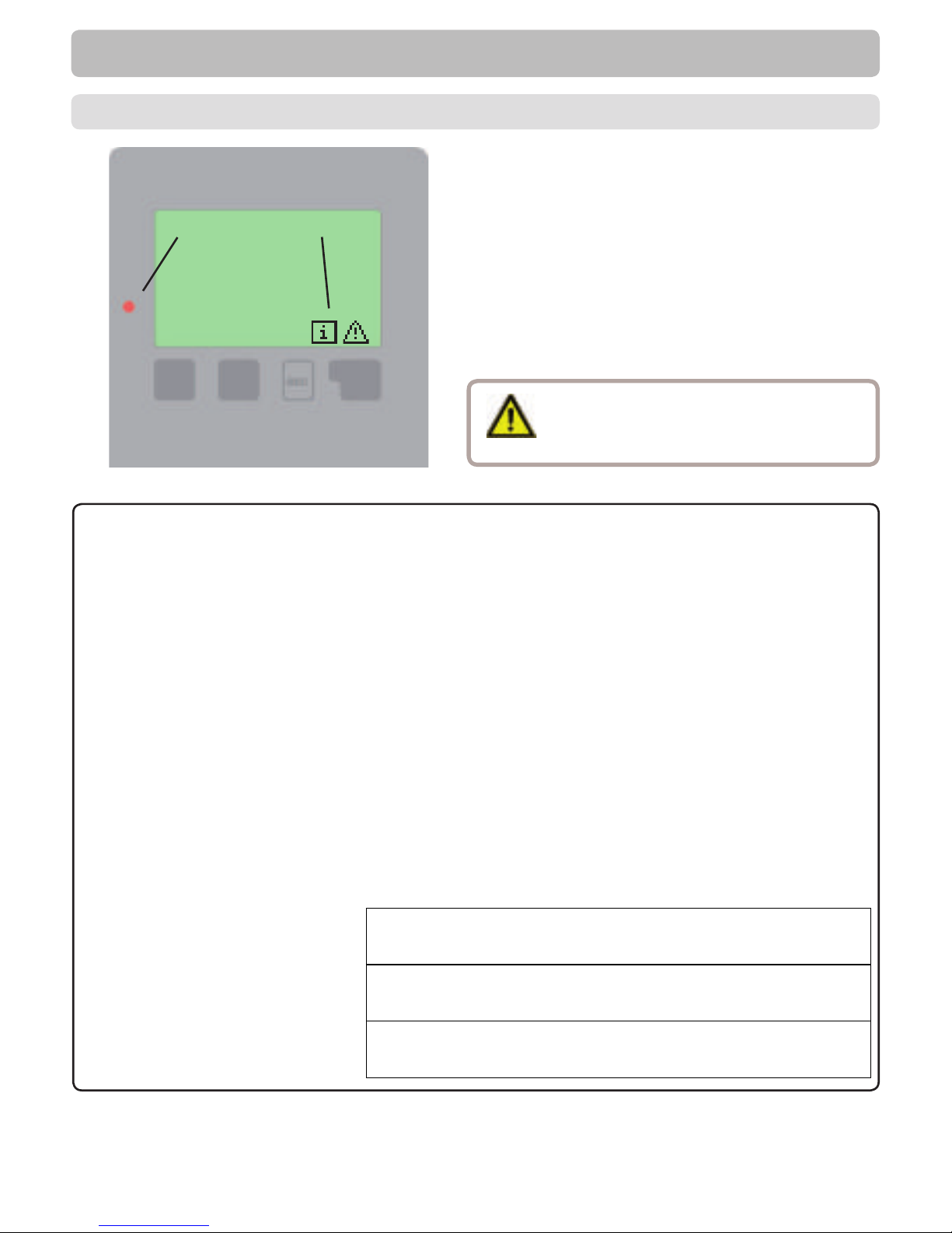
46
Led blinks + warning symbol)
Z.1. Malfunctions with error messages
Malfunctions
If the controller detects a malfunction, the red light
ashes and the warning symbol also appears in the
display. If the error is no longer present, the warning
symbol changes to an info symbol and the red light no
longer ashes.
To obtain more detailed information on the error, press
the key under the warning or info symbol.
Possible error messages: Notes for the specialist:
Sensor x defective Means that either the sensor, the sensor input at the controller or
the connecting cable is/was defective.
(Re sis ta nc e ta bl e se e „B.2. - Temperature resistance table for Pt10 00
sensors“ on page 7)
Collector alarm Means that the collector has fallen/fell below the temperature set
under menu „5.6. - Collector alarm“ on page 25
Restart Means that the controller was restarted, for example due to a
power failure. Check the date&time!
Time & Date This message appears automatically after a mains failure
because the time&date have to be checked, and reset if
necessary.
No ow Is displayed when ∆T between storage and collector is 50° or higher
for 5 minutes without interruption.
Frequent on / off A relay was switched on and off more than 5 times within 5 minutes.
AL failed Is displayed when AL ref-5°C was not measured for the set Al
residence time at the AL sensor.
Danger
Do not try to deal with this yourself.
Consult a specialist in the event of an error!
Page 47
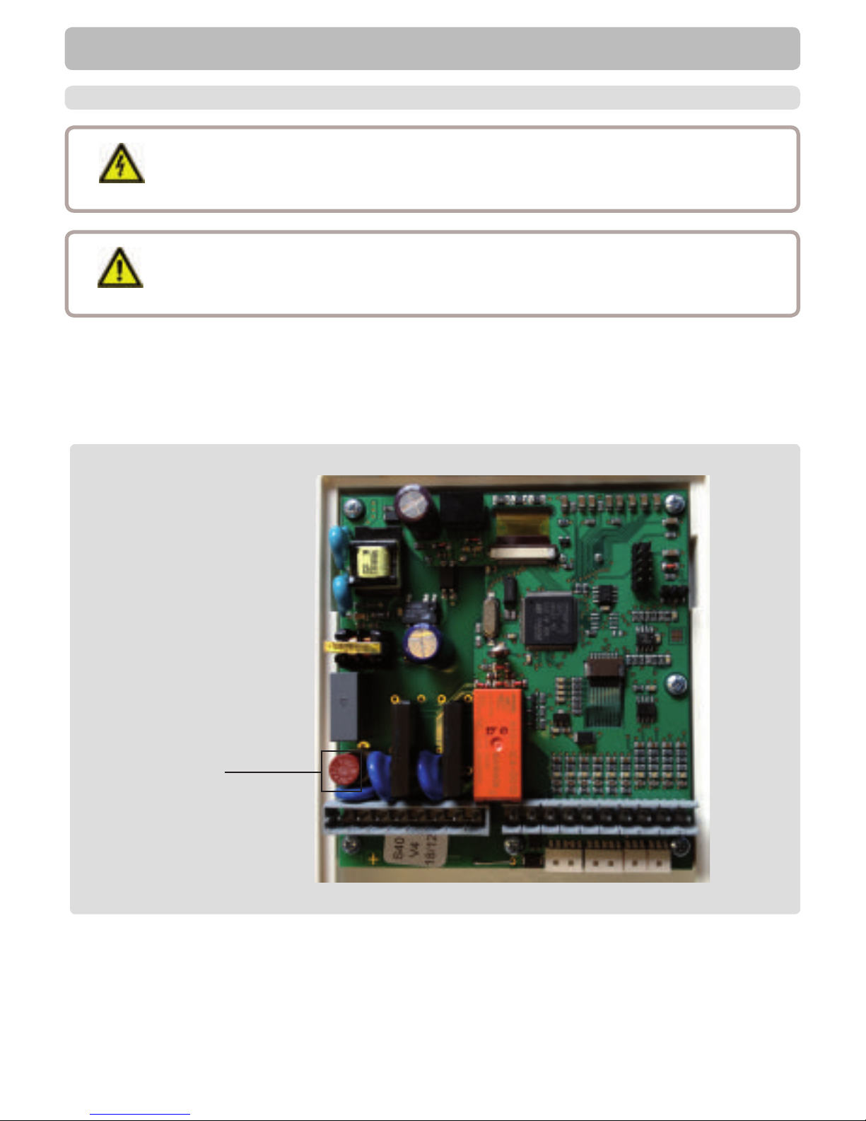
47
Malfunctions
If the mains voltage is switched on and the controller still does not function or display anything, then the
internal device fuse may be defective. In that case, open the device as described under C, remove the old
fuse and check it. Exchange the defective fuse for a new one, locate the external source of the error (e.g.
pump) and exchange it. Then rst recommission the controller and check the function of the switch outputs
in manual mode as described under „3.2. - Manual“ on page 21
Danger
Danger
Repairs and maintenance may only be performed by a specialist. Before working on the unit,
switch off the power supply and secure it against being switched on again! Check for the
absence of power!
Only use the supplied spare fuse or fuses of the same design with the following
speci cations: T2A / 250V .
Z.2 Replacing the fuse
Z.2.1
Fuse
Page 48
48
Maintenance
Performing maintenance:
- Check the date and time (see „6.11. - Time and date“ on page 44)
- Assess/check plausibility of analyses (see „2. - Statistics“ on page 20)
- Check the error memory (see „2.4. - Message log“ on page 20)
- Verify/check plausibility of the current measurement values (see „1. - Measurement values“ on page 20)
- Check the switch outputs/consumers in manual mode (see „3.2. - Manual“ on page 21)
- Possibly optimise the parameter settings
Z.3 Maintenance
Caution
In the course of the general annual maintenance of your heating system you should
also have the functions of the controller checked by a specialist and have the settings
optimised if necessary.
Page 49
49
J. - Appendix
Manual pump settings (see „6.2. - Pump menu“ on page 26)
Appendix Manual pump settings
J.19.1. - Pump
In this menu, precon gured pro les for various pumps can be selected. Please note that individual settings
are still possible even when a pro le has been selected.
J.19.2. - Output Signal
This menu determines the type of pump used: Solar pumps perform at their highest power when the signal
is also maxed, heating pump on the other hand are set to highest power wenn the control signal is at the
lowest. Solar = normal, heating = Inverted.
Settings range: Normal, Inverted / Default setting: Normal
J.19.3. - PWM off
This signal is put out when the pump is switched off (Pumps that can detect cable break need a minimum
signal).
Settings range: (Solar:) 0 to 50% / Default setting: 0% - (Heating:) 50% to 100% / Default setting: 100%
J.19.4. - PWM on
This signal is needed to turn the pump on at minimum speed.
Settings range: (Solar:) 0 to 50% / Default setting: 10% - (Heating:) 50% to 100% / Default setting: 90%
J.19.5. - PWM Max
This determines the the output signal for the highest speed of the pump, that is used e.g. during purging or
manual operation.
Settings range: (Solar:) 50 to 100% / Default setting: 100% - (Heating:) 0% to 50% / Default setting: 0%
J.17.3 - 0-10V off
This voltage is put out when the pump is turned off (Pumps that can detect cable break need a minimum
voltage).
Settings range: (Solar:) 0,0 to 5,0 V / Default setting: 1,0 V - (Heating:) 5,0 to 0,0 V / Default setting: 4 ,0 V
J.17.4 - 0-10V on
This voltage is needed to turn the pump on at minimum speed.
Settings range: (Solar:) 0,0 to 5,0 V / Default setting: 1,0 V - (Heating:) 5,0 to 10,0 V / Default setting: 9,0 V
J.17.5 - 0-10V Max
This determines the output voltage for the highest speed of the pump, that is used e.g. during purging or
manual operation
Settings range: (Solar:) 5,0 to 10,0 V / Default setting: 10,0 V - (Heating:) 0,0 to 5,0 V / Default setting: 0,0
V
J.19.6. - Speed when „On“
This menu determines the calculated and displayed speed of the pump. If e.g. 30% is set here and the
signal set in „PWM on/0-10V on“ is put out, 30% speed is displayed. When the signal set in „PWM max/010V max“ is put out, 100% speed is displayed. Everything in between is calculated accordingly.
Settings range: 10 to 90 % / Default setting: 30 %
J.19.7. - Show signal
Displays the set signal in text and a graphical diagram.
Caution
This function has no in uence on the regulation, but changes only the speed displayed.
Page 50
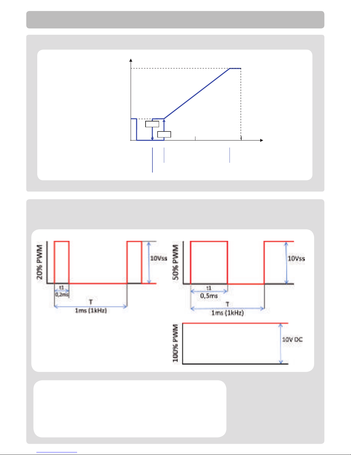
50
J.2.3a Example for pump settings
Max rpm
Speed
5-20% Stop
0-5% Cable break detection
25% Start
25-90% Area of control
Min rpm
PWM-Signal (%)
0 20% 25% 50% 100%
Stop
5%
PWM off 5% - 20%
PWM on >=25% PWM max <= 90%
90%
J.2.3b Technical data
PWM and 0-10V
PWM: 20% to 100%, 1kHz
Designed for a load of
10K Ohm
Technical data PWM:
Technical data 0-10V:
0-10V: 2V to 10V
(20% to 100%)
Designed for a load of
10K Ohm.
10V = 100% Speed
5V = 50% Speed
2V = 20% Speed
0V = Off
Appendix Manual pump settings
Page 51

51
Instead of setting the ow rate for the system using a ow rate limiter, it is better to adjust
the ow rate using the switch on the pump and by means of the “max. speed” setting on the
controller (see. „6.3.4. - max. speed“ on page 28). This saves electricity!
The service values (see „8. - Service values“ on page 45) include not only current
measurement values and operating states, but also all of the settings for the controller. Write
down the service values at least once after commissioning has been successfully completed.
In the event of uncertainty as to the control response or malfunctions the service values are
a proven and successful method for remote diagnosis. Write down the service values (see „8.
- Service values“ on page 45.) at the time that the suspected malfunction occurs. Send the
service value table with a brief description of the error to the specialist or manufacturer.
In the programs with pool the charging of the pool, e.g. for winter operation, can be switched
off using a simple function. To do this, simply press and hold the “esc” key down for several
seconds on the diagram/overview screen. A message appears on the display as soon as the
pool is switched off or when the pool is switched on again.
To protect against loss of data, record any analyses and data that are particularly important to
you (see 2.) at regular intervals.
Useful notes/tips and tricks
Page 52

GRANT ENGINEERING (UK) LTD
Hopton House, Hopton Industrial Estate, Devizes, Wiltshire. SN10 2EU
Telephone: +44 (0)1380 736920 Fax: +44 (0)1380 736991
Email: [email protected] Website: www.grantuk.com
 Loading...