

Page 1
Low temperature
circulator
LTC4
Operating Manual
Page 2

Grant Instruments, based near Cambridge, England is a world leader in the
manufacture and design of equipment for sample preparation, scientific analysis, data
acquisition and data analysis providing solutions to the global scientific and industrial
markets.
Standards Compliance and Quality
Grants’ brand and reputation are based around quality, reliability and accuracy. We
ensure our products stringently meet all necessary international safety standards.
We pay particular attention to the safety testing of products and remain at the forefront of
the product safety standard for laboratory equipment IEC 61010-1. The company is
committed to operating its safety test laboratory in accordance with the requirements of
ISO 17025.
Grant operates a Quality Management System that complies with the requirements of BS
EN ISO 9001:2008.
Beyond compliance to the standard, Grant is committed to continually improving in
everything we do; with particular emphasis on understanding what matters to our
customers and suppliers, and designing our systems and work to meet their needs.
If you have any feedback on Grant’s products or services we would like to hear from you.
Please send all feedback to:
Quality Manager
Grant Instruments (Cambridge) Ltd
Shepreth
Cambridgeshire
SG8 6GB
UK
Tel: +44 (0) 1763 260 811
Fax: +44 (0) 1763 262 410
E-mail: feedback@grantinstruments.com
Page 3

Contents
Contents 2
1.0 Use of products 4
2.0 How to use this operating manual 4
3.0 Safety information 4
3.1 Safety compliance 4
3.2 Safety symbols 4
3.3 Safety warnings 5
4.0 Operating instructions 6
4.1 Unpacking instructions 6
4.2 Fitting the controller to the Refrigeration unit 6
4.3 Recommended liquids 6
4.4 Installation 8
4.5 Electrical supply 8
5.0 Operating procedures 9
5.1 Operation 9
5.1.1 Liquid level 9
5.1.2 Operation above 60°C 9
5.1.3 Setting the over-temperature thermostat 9
5.1.4 Using the control unit pump 10
5.1.5 Using the switch over relay ouput 10
5.1.6 Emptying the LTC4 11
5.1.7 Setting up and switching on 11
5.2 Using the LTC4 12
5.2.1 Product description, control unit 12
5.2.2 Product description, user interface and controls 12
5.2.3 Product desciption, rear panel connections 13
5.2.4 Communications ports 13
5.2.5 Switched relay port 13
5.2.6 External probe input 13
5.2.7 Product description, refrigeration unit front panel (grille removed) 14
5.2.8 Product description, refrigeration, rear panels 15
5.2.9 Display. Explanation of home screen icons. 15
5.2.10 Setting the control temperature 15
5.2.11 Running a bath preset 16
5.2.12 Running a countdown timer 16
5.2.13 Running a program 17
5.2.14 Activating standby mode 17
5.2.15 Accessing the settings menu 18
5.3 Viewing, editing and saving settings 19
5.3.1 Configuring a preset 19
5.3.2 Selecting a liquid type 20
5.3.3 Selecting a temperature probe type 21
5.3.4 Configuring high and low temperature alarms 22
5.3.5 Setting the buzzer volume level 25
5.3.6 Selecting a language 25
5.3.7 Relay test and configuration 26
5.4 Completing a calibration 27
5.4.1 Restoring factory calibration settings 29
6.0 Technical specifications 30
6.1 Operating conditions 30
6.2 Electrical details 30
6.3 Specification 30
7.0 Technical Tips 31
LTC4 31115 V1
Operating Manual Page 2
www.grantinstruments.com
Page 4

7.1 Which water should you use in your LTC4 tank? 31
7.2 How to prevent rust in LTC4 tanks 31
7.3 How to prevent algae and bacteria? 32
8.0 Warranty information 32
9.0 Maintenance and service 32
9.1 Routine maintenance 32
9.2 Cleaning 32
9.3 Fuses 33
9.5 Routine safety tests 33
9.6 Service 34
10.0 Optional accessories 34
10.1 Alternative pump 34
11.0 Troubleshooting 35
12.0 Contact Grant Instruments 38
13.0 Compliance 38
Notes 39
31115 V1 LTC4
Page 3 Operating Manual
www.grantinstruments.com
Page 5

1.0 Use of products
Caution: Surfaces and heat transfer liquid can be hot during and after use.
Read this manual before using the bath.
Important safety warning.
The following products are covered by this operating manual:
LTC4 & LTC4L
The products listed above low temperature circulators designed for indoor laboratory use
by a professional user.
The LTC4 consists of a TX150 immersion thermostat combined with an R4 refrigeration
unit, with insulated hoses and clips to allow circulation of temperature control fluids to
external equipment.
2.0 How to use this operating manual
This operating manual will allow you to unpack, set-up and operate the R unit correctly
and safely. Important safety information, symbols and warnings are listed below and
should be read carefully. Section 4 gives information about how to unpack and install the
product correctly. Section 5 gives provides operating information for the LTC4. Product
technical specifications and tips are provided in sections 6 and 7. The warranty for this
product is for THREE YEARS and is detailed in section 8 and should be registered by
completing the on-line registration form at www.grantinstruments.com.
If there is a technical matter that this operating manual does not address, or any other
question concerning this product, please contact Grant Instruments or your local
distributor, who will be able to provide any additional information.
3.0 Safety information
3.1 Safety compliance
The LTC4 meets the requirements of international safety standard IEC 61010: Safety
requirements for electrical equipment for measurement, control, and laboratory use.
3.2 Safety symbols
The symbols below are marked on the equipment and throughout this manual to indicate:
LTC4 31115 V1
Operating Manual Page 4
www.grantinstruments.com
Page 6

3.3 Safety warnings
Read the whole of these instructions. Safety may be impaired if they are not
followed.
Only use liquids specified in these operating instructions, within the specified
temperature range. If the alarm lamp is illuminated the liquid temperature may
be above its recommended maximum. Do not inhale the vapours given off as
they may be toxic. Liquids should be safely discarded and replaced.
Do not use the R series unit with flammable heat transfer liquids.
Do not use the R series unit to heat any sample material that could cause a fire
or any other kind of hazard.
Do not use the equipment in an area where there are aggressive or explosive
chemical mixtures.
If a potentially hazardous liquid is spilt onto or inside the equipment, disconnect
it from the power supply and have it checked by a competent person.
Before moving, disconnect from the mains power supply
It is the user’s responsibility to carry out appropriate decontamination if
hazardous material is spilt on the equipment.
If the alarm lamp is illuminated do not touch the liquid or the tank base, they
may be very hot. Refill carefully, a hot heater can cause a spattering of very hot
water droplets and scalding steam.
Do not touch surfaces which become hot during high temperature operation.
31115 V1 LTC4
Page 5 Operating Manual
www.grantinstruments.com
Page 7
4.0 Operating instructions
The LTC weighs 39.5kg . Take necessary precautions when moving and lifting.
2
1
4.1 Unpacking instructions
Standard equipment includes:
LTC4 low temperature circulator
Pump connector kit
4 x Jubilee clips
6m of insulated hose
Mains cord
Operating manual
Remove packing materials carefully and retain them for future shipment or storage of the
equipment.
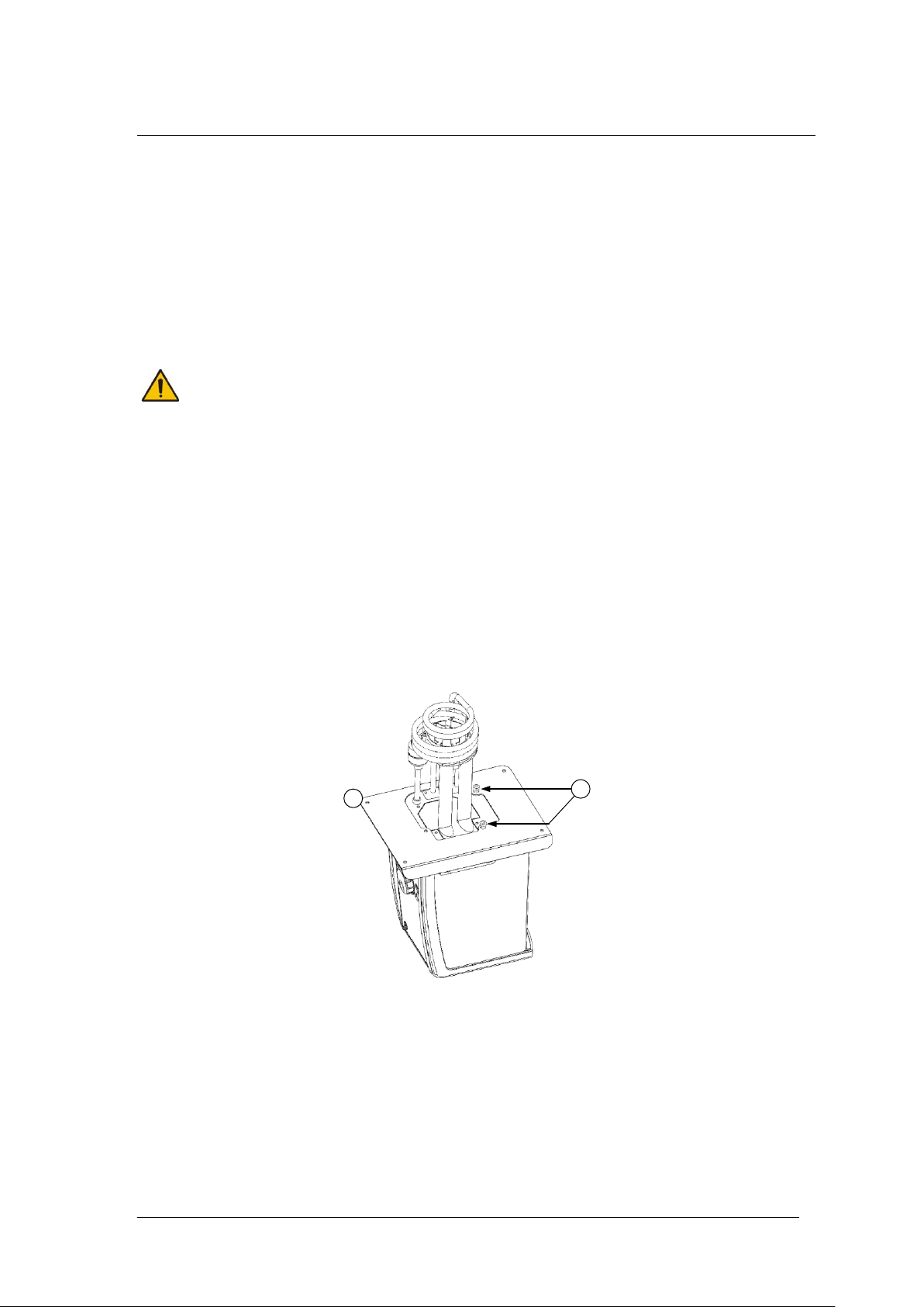
4.2 Fitting the controller to the Refrigeration unit
The TX150 unit can be fitted in two orientations on the LTC4 unit facing over the tank
opening or outwards
1. Remove the bridge plate from the LTC4 unit tank by unscrewing the four black thumb
screws.
2. Fit the Optima unit through the hole in the bridge plate and align using the locating
threads. Secure using the retaining nuts. Hand tighten only.
3. Re-attach the bridge plate onto the R unit, using the retained black thumb screws.
4.3 Recommended liquids
The following table lists the recommended liquids for different temperature ranges.
Always ensure the liquid used is safe and suitable for your working temperature. If using
non-recommended heat transfer liquids, it is the responsibility of the user to conduct an
assessment to ensure the intended fluid is compatible with the LTC4. If in doubt please
contact the Grant technical support team.
LTC4 31115 V1
Operating Manual Page 6
www.grantinstruments.com
Page 8

To ensure protection the overtemperature cut-out must be set appropriately for
the heat transfer liquid selected (see table below).
If using non-recommended heat transfer liquids it is important to set the overtemperature cut-out to a value no higher than 25°C below the fire point of the
liquid.
Use fume extraction when using silicone fluids at elevated temperatures
Temp range
Recommended liquid
Comments
-50°C to 50°C
Silicone oil – low
viscosity
Bayer silicone M3. Follow the manufacturer’s
instructions. For safe disposal consult your
local regulations.
-30°C to 30°C
50% water, 50%
antifreeze (inhibited
ethylene glycol)
WARNING: Ethylene glycol is toxic – follow the
manufacturer’s instructions.
For safe disposal consult your local
regulations.
Use a lid to reduce the dilution of the mixture
caused by condensing water vapour from the
air, and to maintain the cool down rate.
0°C to 30°C
80% water, 20%
antifreeze (inhibited
ethylene glycol)
5°C to 99.9°C
Water*
Water can be used but care should be taken
above 60°C as hot vapour can be dangerous.
Use a lid or polypropylene spheres above
60°C to ensure good performance & reduce
evaporation.
At temperatures approaching 99°C the
temperature performance will be affected due
to localised boiling.
The units should not be used to boil water.
70°C to 120°C
Silicone fluid
Viscosity ~20cs
Flash point ≥230°C
Fire Point ≥280°C
Dow Corning DC200/20 silicone fluid is a
suitable liquid – follow the manufacturer’s
instructions.
For safe disposal consult your local
regulations.
* See section 7.1 for further details
31115 V1 LTC4
Page 7 Operating Manual
www.grantinstruments.com
Page 9

4.4 Installation
Place the unit a level, non-combustible surface. Ensure that the mains plug and
the switch at the rear of the unit are easily accessible.
If the equipment has been transported or stored in cold or humid conditions,
condensation may form inside it. If that could have happened, allow time (at
least 2 hours at room temperature) for the condensation to evaporate before
using the equipment.
Do not block or restrict ventilation slots.
Do not connect to a power supply or switch on before filling the tank.
Drain before moving the unit. Before draining allow the liquid to cool below
50˚C.
Do not touch the condenser fins, they are sharp and may cause injury.
Connect the LTC4 to a grounded (earthed) electrical power supply with voltage
and frequency within the range specified on the serial number plate.
The LTC4 must only be connected to the mains using the mains cord supplied
or one with an identical rating (see section 9.4)
Ensure the mains switch and isolating device (power supply connector) are
easily accessible during use.
After transportation, let the unit stand in its intended working position for six hours. This
is to allow the oil to drain to the bottom of the compressor. This is normal procedure for
refrigeration compressors. Allow at least 100mm clearance from obstructions on all
sides so that there is free air flow through the unit, from the front to the back (this also
has the advantage that air is not blowing directly out of the sides onto instruments next to
the LTC4).
4.5 Electrical supply
LTC4 31115 V1
Operating Manual Page 8
www.grantinstruments.com
Page 10

5.0 Operating procedures
Take care when lifting and removing the lid as it may be hot. Steam and hot
vapours can cause scalding.
5.1 Operation
5.1.1 Liquid level
Fill the tank to an appropriate level with a liquid suitable for your working temperature;
see section 4.3 for liquid options. Allow for thermal expansion and contraction of the
liquid during operation and for any liquid in external circulation paths. If using liquids that
can evaporate then periodic checking and refilling should be completed. The low level
float switch will alarm if the liquid level drops below the minimum required level and the
unit will switch off the heater and stop temperature control.
5.1.2 Operation above 60°C
A lid or polypropylene spheres must be used above 60°C to maintain temperature control
and to ensure that the bath fluid temperature reaches the set point. They will save
energy by preventing excessive evaporation and reduce the frequency that the bath
needs to be refilled.
5.1.3 Setting the over-temperature thermostat
An over-temperature cut-out dial with a temperature scale is located at the top right of the
unit. The over-temperature probe independently monitors the bath temperature and
switches the heater off if it goes above the cut-out threshold.
Coarse setting of the over-temperature thermostat
Rotate the temperature cut-out dial in line with the marked scale to the desired setting.
This should be higher than the set temperature to avoid operating the cut-out before the
set temperature has been reached.
If the alarm is triggered the sounder can be silenced by pressing either the F or S button
once. To continue to use the TX150/TXF200, let the bath liquid cool by at least 5°C,
either naturally or by replacing the liquid, switch the unit off, wait 10 seconds and switch it
on again to clear the alarm. To avoid nuisance tripping the trip point needs to be set at
least 5°C above the desired control temperature.
Alternative setting of the over-temperature thermostat
Rotate the temperature cut-out dial to maximum (or at least a value above the level
required) and configure the set temperature to the cut-out level required. Leave the bath
to reach the set temperature and stabilise for at least 5 minutes. Turn the cut-out dial
slowly anticlockwise until an over-temperature fault is displayed on screen and the alarm
sounds continuously. This gives an over-temperature trip point at the set temperature.
The audible alarm can be cancelled by pressing either the F or S button once.
To continue to use the TX150/TXF200, let the bath liquid cool by at least 5°C, either
naturally or by replacing the liquid, switch the unit off, wait 10 seconds and switch it on
again to clear the alarm. To avoid nuisance tripping the trip point needs to be set at least
5°C above the desired control temperature.
31115 V1 LTC4
Page 9 Operating Manual
www.grantinstruments.com
Page 11
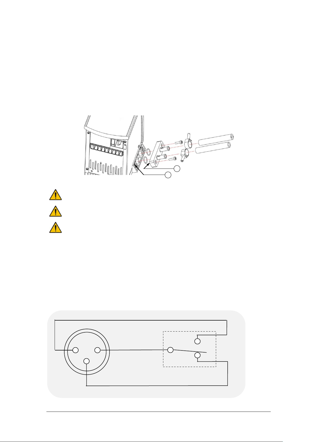
5.1.4 Using the control unit pump
Always use pump connectors and hoses that are suitable for the operating
temperature and liquid used. Check the pipe connections are secure.
Never disconnect any pipes or hoses while they contain very hot or very cold
liquids or while the LTC4 unit is pumping.
Never use silicone oil with silicone tubing.
3 2 1
Normally Closed
Normally Open
Common
Rear
Panel
connector
Relay
B
A
The LTC4 allows liquid to be pumped around a closed external system (not open to the
atmosphere). It cannot be used for circulation through an external open tank. The pump
is fitted with a blanking plate as standard. Fit a pump connector plate as shown below.
Ensure o-rings are located in the grooves, use silicone grease to hold the o-rings in
place. Note: the blanking/connector plates have a locating hole (see A below) to assist
correct alignment onto the pump moulding. It is important to verify the hole is aligned with
the corresponding locating pin (see B below) on the pump moulding. Failure to do so will
result in a leaking connection. Retain the blanking plate for refitting when the pump is no
longer required.
Pumping heat transfer liquid around an external system can lead to hazards that are
outside the control of Grant Instruments. It is essential that the user conducts a risk
assessment of the entire equipment installation to ensure that correctly rated materials
have been used throughout and that the system can be used safely.
5.1.5 Using the switch over relay ouput
An internal relay provides switch over contacts that can be used to control external
equipment. The pin connections on the rear panel 3 pin circular connector are:
LTC4 31115 V1
Operating Manual Page 10
www.grantinstruments.com
Page 12

For the connecting cable use a mating XLR style connector such as the NC3FXX
The relay is rated 24Vac or dc at 2A; to prevent injury or equipment damage,
do not connect to greater voltages or attempt to switch greater currents.
Voltages as low as 22Vac can be hazardous in locations where wetting of the
skin can occur. When making up cable to connect your equipment to the relay
connector, on the TX150/TXF200, make sure that the insulation system used is
adequate to provide protection against the voltages output by your equipment
for switching by the relay.
Always use the correct size cable with correct class of insulation for the voltage
being switched. If in doubt contact the technical support team at Grant.
Allow the liquid temperature to fall below 50˚C before emptying.
Ensure all hoses are connected securely. Liquid will begin pumping
immediately once LTC4 is switched on.
manufactured by Neutrik AG
The switch over contacts are rated at 24V AC or DC 2A maximum.
5.1.6 Emptying the LTC4
The R unit tank should be emptied to a safe level prior to moving. A drain tap is included
on R2, R3, R4 & R5 units to allow convenient emptying. See section 5.2.3 for full details.
5.1.7 Setting up and switching on
Follow instructions in section 5.1.3 to attach the pump connector plate and insulated
hose. Before filling and switching on, attach the open end of the hose to the application,
taking care to note the inlet and outlet.
Add the appropriate working liquid to the bath to at least the minimum recommended fill
level such that the float level switch is fully raised.
The control unit is connected directly to the mains supply with the IEC cable supplied
with the unit (230V units only).
Connect the refridgeration unit directly to the mains using the IEC cable provided).
Switch on the LTC4 control unit using the power switch on the rear. The motor will start
immediately and the buzzer will sound while the unit starts up. Switch on the
refrigeration unit using the power switch on the front of the unit. The LTC4 will start to
control at the set temperature
31115 V1 LTC4
Page 11 Operating Manual
www.grantinstruments.com
Page 13
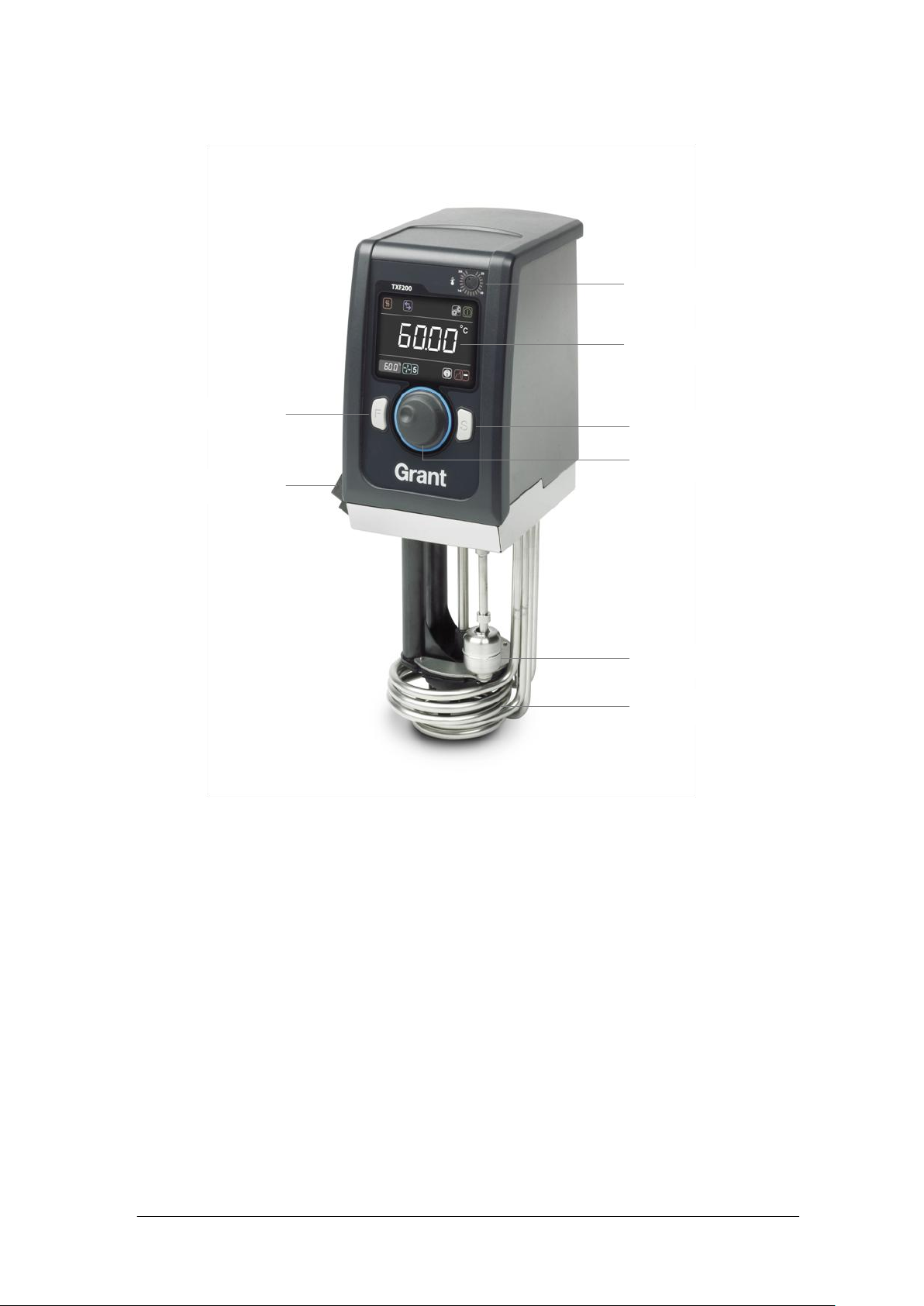
5.2 Using the LTC4
Over-temperature dial
Full colour display
Select button
Main dial
Float switch
Heater coils
Pump outlet plate
Function button
5.2.1 Product description, control unit
5.2.2 Product description, user interface and controls
The TX150 features a full colour graphic display, a main dial and two buttons F and S.
All functions (setting temperature, pump speed, countdown timer, presets, programs
settings and standby mode) can be configured from the home screen. Navigation around
the home screen is achieved by rotating the main dial which moves a white curser to
highlight function icons. Pressing the S button whilst the icon is highlighted will change
the colour of the curser to red, make the icon active and allow changes to be made, or in
the case of the settings icon, further menus to be displayed.
The primary function of the F button is to exit functions and menus. If F is pressed when
in the home screen whilst the cursor is white the settings menu is displayed
LTC4 31115 V1
Operating Manual Page 12
www.grantinstruments.com
Page 14
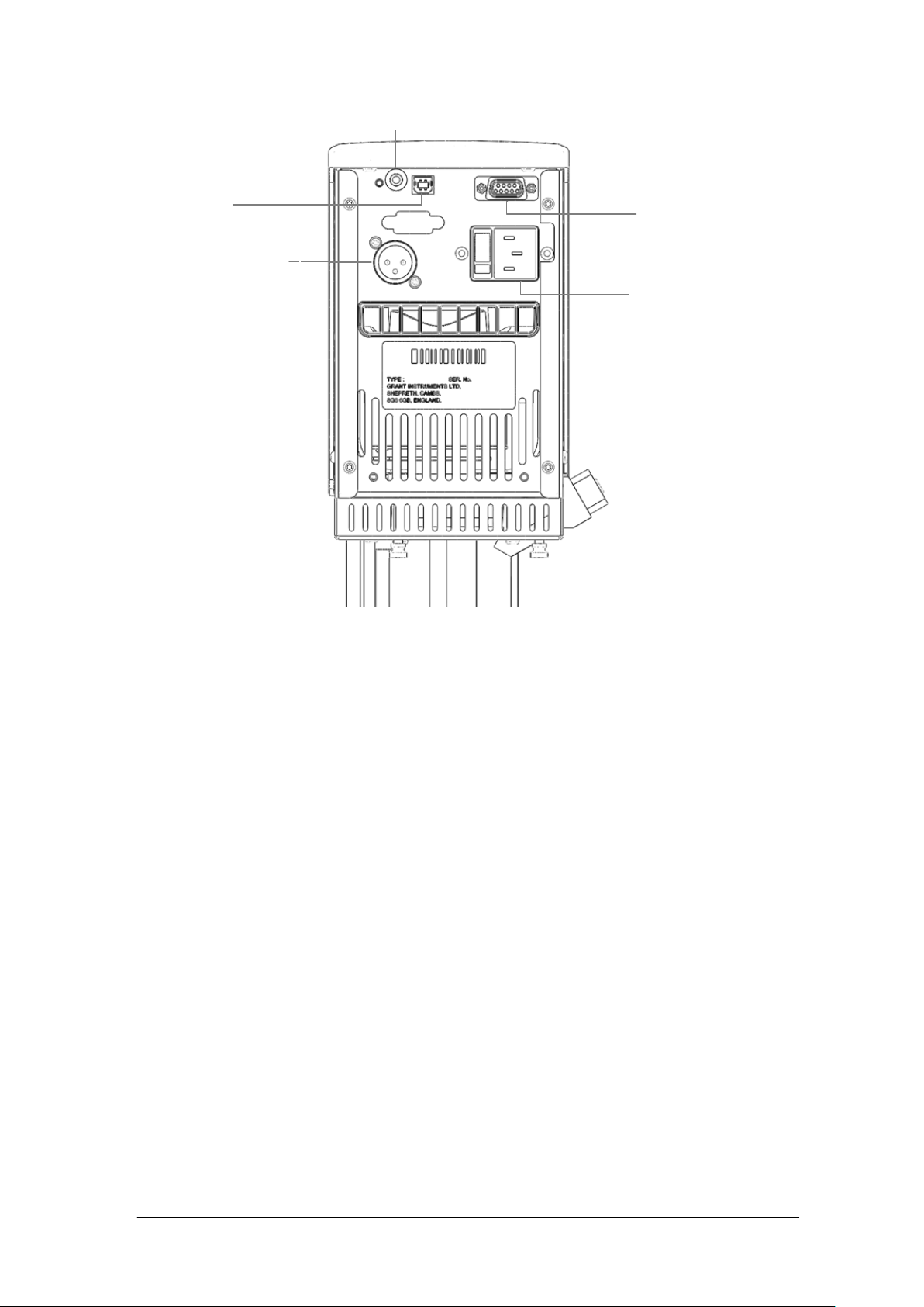
5.2.3 Product desciption, rear panel connections
RS232 communcations
port
Mains power input
USB port
Switched relay port
External probe input
5.2.4 Communications ports
The TX150 and TXF200 provide a RS232 and a USB data port for communication with a
PC running Grant Labwise™ software. Labwise™ provides the abilty to remotely
configure, control, monitor programs as well as log program temperature data.
Only use a RS232 cable supplied by Grant instruments.
The USB cable is a Type A to Type B style
5.2.5 Switched relay port
An internal relay provides switch over contacts that can be used to control external
equipment. See Section 5.1.5 for details of the relay contacts and connector type.
5.2.6 External probe input
For connecting an external PT1000 thermocouple temperature probe available from
Grant instruments
31115 V1 LTC4
Page 13 Operating Manual
www.grantinstruments.com
Page 15

5.2.7 Product description, refrigeration unit front panel (grille removed)
Power switch
Over temperature protection reset
Freezing protection, 5˚C switch
Drain port
Drain insert
Condenser fins
The over temperature protection reset: protects the unit from overheating by the over
temperature cut-out. This will be actuated when the working fluid is raised above
between 110°C and 120°C. The unit can be reset by waiting for the liquid to cool below
100°C, then unscrewing the black cap and pushing in the revealed button.
The freezing protection switch uses a low temperature thermostat to ensure the working
fluid never drops below 5°C. With the switch in the depressed/in position the cooling will
be switched off by a low temperature protecting thermostat. If water is used in the bath
this will prevent it from freezing. In the out/off position the thermostat is bypassed
allowing the unit to run at temperatures below 5°C.
The drain port and insert allow convenient emptying of the refrigeration bath. To drain
the unit first remove the drain insert from the holder and connect a suitable length of
hosing with a bore of 12.7mm (½’') to the drain insert. Have the non connected end of
tubing in a receptacle, suitable for the liquid to be drained. Push the drain insert into the
drain port and let the liquid drain. To release the drain insert push down the grey button
on the drain body and extract the drain insert. Liquid to be drained should not be below
10°C or above 50°C.
LTC4 31115 V1
Operating Manual Page 14
www.grantinstruments.com
Page 16

5.2.8 Product description, refrigeration, rear panels
1. Rotate the dial until the set temperature icon is
highlighted, press the S button.
2. Rotate the dial to set the desired temperature.
If no key is pressed for 10 seconds or if F is
pressed, the set temperature icon is no longer
active and will remain at its original value.
3. Press S to store the requested value.
If the temperature selected is higher than the
:
.
°c
.
°c
:
.
°c
Settings
Standby
Actual temperature
External probe
Program
Preset
Countdown timer
Communication
Relay
Heater on
indicator (high
power)
Set temperature
Pump speed
(TXF200 only)
.
°c
Communications lead
fuse & socket
Power supply for
accessory pumps
Mains inlet
220-240V unit
Communications lead
fuse & socket
Power supply for
accessory pumps
Mains inlet
110-120V unit
Main fuses
5.2.9 Display. Explanation of home screen icons.
5.2.10 Setting the control temperature
31115 V1 LTC4
Page 15 Operating Manual
www.grantinstruments.com
Page 17

current liquid temperature the heater will switch
on and the heater icon will be displayed.
5.2.11 Running a bath preset
1. Rotate the dial until the preset icon is
highlighted, press the S button.
2. Rotate the dial to select the desired preset 1, 2
or 3, press S to run the preset.
The preset will automatically start as soon as S
is pressed.
If no key is pressed for 10 seconds or if F is
pressed the preset icon is no longer active and
will remain at its original value.
1. Rotate the dial until the countdown timer icon is
highlighted, press the S button.
The countdown timer will display the last
countdown time set.
If no key is pressed for 10 seconds or if F is
pressed the countdown timer setting is no longer
active and will remain at its original value.
2. Rotate the dial to set the desired countdown
time, press S to store.
The countdown timer will begin counting down
from the set time. At the end of the countdown
timer period a buzzer will sound. This can be
cancelled by pressing F or S.
:
.
°c
.
°c
:
.
°c
.
°c
Each TX150/TXF200 contains three presets which can be configured to different set
temperatures and in the case of the TXF200 the pump speed can additionally be
configured. This allows the bath to be conveniently run at frequently used temperatures
and pump speeds. See section 5.3.1 for information on preset configuration.
Preset temperatures and set temperatures are limited to the model type and the liquid
selection. The TX150 settable range is between -50°C and 150°C increasing to between
-50°C and 200°C for the TXF200
5.2.12 Running a countdown timer
The countdown timer on the TX150/TXF200 can be set in the range of 1 minute to 99
hours. The countdown timer will sound a buzzer at the end of a countdown period. See
section 5.3.2 for information on configuring countdown timer expiry actions.
To cancel an active countdown timer:
1. Rotate the dial until the countdown timer icon is highlighted, press the S button.
2. Press the F button to cancel the countdown timer.
The countdown timer is stopped.
LTC4 31115 V1
Operating Manual Page 16
www.grantinstruments.com
Page 18

5.2.13 Running a program
1. Rotate the dial until the program icon is
highlighted, press the S button.
If no key is pressed for 10 seconds or if F is
pressed, the program icon is no longer active and
will remain at its original value.
2. Rotate the dial until program 1 is displayed. By
default the TX150 will display program “–“
indicating that no program is selected. Press S to
select the program.
The selected program will start. The display will
show the target temperature of the first segment
and the countdown timer will indicate the duration
of the program remaining. Whilst a program is
running only the Standby icon can be selected.
At the end of a program the buzzer will sound, this
can be cancelled by pressing F or S.
:
.
°c
.
°c
The TX150 has the capability to run automatic temperature profiles called programs.
The TX150 has the capacity to store 1 program containing 30 individual temperature/time
segments.The TXF150 can only be configured and edited using Grant Labwise™
software When a program is running icon access is limited to the standby and program
functions
To stop a program
1. Rotate the dial until the program icon is highlighted, press the S button.
If no key is pressed for 10 seconds or if F is pressed, the program icon is no longer
active and will remain at its original value and the program will continue to run.
2. Rotate the dial until the “–“ is displayed, press S to select
The program will stop. The display will remain at the set temperature reached when
the program was stopped, the countdown timer will stop at the remaining time and
the pump speed will display the last speed set.
5.2.14 Activating standby mode
In standby mode the TX150 is still powered, however key functions (heating, pump,
countdown timer and programs) are switched off. In standby mode access is limited to
the settings menu, enabling the functions such as alarms and programs to be configured
while the unit is not operating.
Note. When entering standby mode the pump will remain on for 5 minutes to allow
internal cooling to continue.
If a countdown timer has been set or a program is running before activating standby
mode they will be terminated.
31115 V1 LTC4
Page 17 Operating Manual
www.grantinstruments.com
Page 19

1. Rotate the dial until the standby icon is
highlighted, press the S button.
The temperature and countdown timer values
are no longer displayed.
2. To resume operation, rotate the dial until the
standby icon is highlighted, press the S button.
The display returns to the home screen and the
TX150 resumes operation at the last
temperature and pump speed set.
1. Rotate the dial until the settings icon is
highlighted, press the S button.
The settings menu is displayed, with presets
highlighted at the top of the list.
Shortcut to settings menu. Pressing F whilst in
the home screen when the cursor is white will
automatically display the settings menu
2. Rotate the dial to scroll up and down the list, until
the desired setting is highlighted, press the S
button to select. The desired settings menu is
displayed.
Pressing F returns to the home screen without
making changes.
.
°c
Presets
Settings
Liquid
Probe
Alarms
:
.
°c
.
°c
:
.
°c
.
°c
:
.
°c
.
°c
5.2.15 Accessing the settings menu
The settings menu provides access to the following settings screens:
preset selection and definition, program selection and definition, liquid type, probe
(internal or external), alarms, buzzer level and language. Section 5.3 provides detailed
information on viewing, editing and saving settings.
LTC4 31115 V1
Operating Manual Page 18
www.grantinstruments.com
Page 20

5.3 Viewing, editing and saving settings
1. Rotate the dial until the settings icon is highlighted,
press the S button.
Pressing F returns to the home screen without
making changes.
2. Rotate the dial to scroll up and down the list, until
preset is highlighted, press the S to select.
Pressing F returns to the settings screen without
making changes.
3. Rotate the dial to display preset icon 1, 2 or 3,
press S to select.
4. Temperature is highlighted, press the S button.
Rotate the dial to define the temperature. Press S
to set.
Pressing F restores the original preset temperature
with temperature highlighted.
Pressing F restores the original preset pump speed
with pump speed highlighted.
To save the temperature and pump speed
configuration, rotate the dial to highlight save and
press S
The display returns to the settings menu screen.
Repeat procedure to configure presets 2 and 3
5. Press F to return to the home screen.
.
°c
Temperature
Preset
Save
°c
.
.
°c
Presets
Settings
Liquid
Probe
Alarms
.
°c
Presets
Settings
Liquid
Probe
Alarms
:
.
°c
.
°c
5.3.1 Configuring a preset
31115 V1 LTC4
Page 19 Operating Manual
www.grantinstruments.com
Page 21

5.3.2 Selecting a liquid type
Liquid
Set temperature range
Water
0°C to 100°C
Water-Glycol
*-30°C to 50°C
Low Temp Oil
-50°C to 50°C
High Temp Oil
†
70°C to 150°C (TXF150)
¥
70°C to 200°C (TXF200)
1. Rotate the dial until the settings icon is
highlighted, press the S button.
2. Rotate the dial to scroll up and down the list until
liquid is highlighted, press S to select.
Liquid options are displayed.
3. Rotate the dial to scroll through the liquid options,
press S to save the selection.
The display returns to the settings screen.
4. Press F to return to the home screen.
.
°c
Presets
Settings
Liquid
Probe
Alarms
Water
.
°c
Presets
Settings
Liquid
Probe
Alarms
:
.
°c
.
°c
The liquid type determines the limits of the set temperature range.
Selection of the liquid types below changes the settable temperature range as follows:
* Water-Glycol (50% water, 50% antifreeze (inhibited ethylene glycol)
†
High Temp Oil (silicone fluid with the following characteristics: viscosity 20 centistokes,
flash point ≥230°C, fire point ≥280°C).
¥
High Temp Oil (silicone fluid with the following characteristics: viscosity 50 centistokes,
flash point ≥285°C, fire point ≥340°C). See section 4.3 for full description of
recommended bath liquids.
LTC4 31115 V1
Operating Manual Page 20
www.grantinstruments.com
Page 22

5.3.3 Selecting a temperature probe type
1. Rotate the dial until the settings icon is
highlighted, press the S button.
2. Rotate the dial to scroll up and down the list until
probe is highlighted, press S to select.
Probe options are displayed
3. Rotate the dial to scroll through the probe types
(external or internal), press S to save the
selection
The display returns to the settings screen.
The external probe icon will be displayed on the
home screen
4. Press F to return to the home screen.
.
°c
Probe
Settings
Alarms
Buzzer
Language
Internal
.
°c
Probe
Settings
Alarms
Buzzer
Language
:
.
°c
.
°c
The bath temperature can be controlled using an internal or external temperature probe.
31115 V1 LTC4
Page 21 Operating Manual
www.grantinstruments.com
Page 23

5.3.4 Configuring high and low temperature alarms
Liquid temp
Time
5
10
15
Temp
Alarm
Value -20˚C
Set temp -10˚C
Low temperature fixed alarm.
Liquid temp
Set
temperature
Deviation
5°C
Temp
Time
5
10
15
High temperature deviation alarm.
Alarm value
There are three functions in the alarm menu.
1. A high alarm function, which causes an alarm condition when the bath
temperature goes higher than the alarm value. The alarm value can be set as a
fixed temperature above the set temperature or a deviation offset value above the
set temperature. Below is an example of a high temperature deviation alarm,
where the deviation value has been set to 5˚C.
2. A low alarm function, when the bath temperature goes lower than the alarm
value. The alarm value can be set as a fixed temperature below the set
temperature or a deviation offset value below the set temperature. Below is an
example of a low temperature fixed alarm, where the fixed temperature value has
been set to -20˚C.
3. A hold-off time can be entered, which is a user adjustable time of between 0 and
LTC4 31115 V1
Operating Manual Page 22
21mins for which the alarms remain muted after either button has been pressed
to acknowledge an alarm condition. If the bath returns to the value such that the
alarm level is not exceeded the alarm will cancel. However, if the temperature
remains outside the alarm level the alarm condition will re-occur after this hold-off
time.
www.grantinstruments.com
Page 24

1. Rotate the dial until the settings icon is highlighted,
press the S button.
2. Rotate the dial to scroll up and down the list until
alarms are highlighted, press S to select.
3. High alarm mode is highlighted, press S to
select.
4. Rotate the dial to select fixed temp, deviation or
disabled. Press S to select.
The high alarm screen is displayed
.
°c
High Alarm mode
Alarm Settings
Low Alarm mode
Save
Fixed Temp
Disabled
Holdoff mm:ss
.
°c
Probe
Settings
Alarms
Buzzer
Language
:
.
°c
.
°c
Liquid temp
Set point
temp
Temp
Time
5
10
15
Hold off time.
Alarm value
0
Hold off period 8 mins
Alarm acknowledged
2
Each alarm can be programmed to latch, activate an audible buzzer and a relay. Alarms
are cancelled by pressing the F or S button or if an alarm condition has been removed.
31115 V1 LTC4
Page 23 Operating Manual
www.grantinstruments.com
Page 25

5. Temperature is highlighted, press S to select.
6. Rotate the dial to define the temperature value,
press S to set.
7. Rotate the dial to highlight latching, press S to
select.
8. Rotating the dial will display on/off, press S to
select.
When latching is on, a temperature alarm
continues unless acknowledged by the user even
if the temperature comes back in range
9. Rotate the dial to highlight relay, press S to select.
10. Rotating the dial will display on/off, press S to
select.
11. Rotate the dial to select buzzer, press S to select.
12. Rotating the dial will display on/off, press S to
select.
13. Rotate the dial to save, press S. The display
returns to the alarm settings screen. The
procedure can be repeated to configure a
deviation alarm and for the low alarm function.
14. Rotate the dial to highlight holdoff, press S to
select.
15. Rotate the dial to select a holdoff time (over a
range of 5 to 600 seconds), press S to select.
Rotate the dial to save, press S to save all
settings.
The display will return to the settings menu
16. Press F to return to the home screen
.
°c
High Alarm mode
Alarm Settings
Low Alarm mode
Save
Fixed Temp
Disabled
Holdoff (s)
.
°c
Temperature
Latching
High Alarm
Off
°c
.
On
Relay
Buzzer
On
Save
LTC4 31115 V1
Operating Manual Page 24
www.grantinstruments.com
Page 26

5.3.5 Setting the buzzer volume level
1. Rotate the dial until the settings icon is
highlighted, press the S button.
2. Rotate the dial to scroll up and down the list until
buzzer is highlighted, press S to select.
Volume options are displayed.
3. Rotate the dial to scroll through the volume levels
(low, medium and high and off), press S to save
the selection.
The display returns to the settings screen.
4. Press F to return to the home screen.
1. Rotate the dial until the settings icon is
highlighted, press the S button.
:
.
°c
.
°c
.
°c
Probe
Settings
Alarms
Buzzer
Language
Low
.
°c
Probe
Settings
Alarms
Buzzer
Language
:
.
°c
.
°c
Three buzzer volume levels are available, low, medium and high and off.
5.3.6 Selecting a language
Five language options are available, English, French, German, Italian and Spanish.
31115 V1 LTC4
Page 25 Operating Manual
www.grantinstruments.com
Page 27

2. Rotate the dial to scroll up and down the list until
language is highlighted, press S to select.
Language options are displayed.
3. Rotate the dial to scroll through the language
options (English, French, German, Italian and
Spanish) press S to save the selection.
The display returns to the settings screen.
4. Press F to return to the home screen.
1. Rotate the dial until the settings icon is
highlighted, press the S button.
2. Rotate the dial to scroll up and down the list until
relay is highlighted, press S to select.
Relay options are displayed
.
°c
Alarms
Settings
Buzzer
Language
Relay
:
.
°c
.
°c
.
°c
Probe
Settings
Alarms
Buzzer
Language
English
.
°c
Probe
Settings
Alarms
Buzzer
Language
5.3.7 Relay test and configuration
The TX150 and TXF200 can be configured to switch a relay in the program function.
This function can be tested manually outside the program function by following the
instructions below.
LTC4 31115 V1
Operating Manual Page 26
www.grantinstruments.com
Page 28

3. Rotate the dial to toggle between on/off, press S
to save the selection.
The display returns to the settings screen.
4. Press F to return to the home screen.
User recorded
Temperature
Measured
Temperature
t3
t4
t2
t1
T4
T3
T2
T1
.
°c
Alarms
Settings
Buzzer
Language
Relay
On
5.4 Completing a calibration
The TX150 allows up to five temperature points to be calibrated. The calibration menu
can be accessed by simultaneously pressing the F and S buttons for 3 seconds
The calibration temperatures are constrained by the temperature limits of the liquid type
setting. Calibration should be carried out using a traceable reference thermometer with
an accuracy of at least 0.1°C. This thermometer should be held securely in the centre of
the bath or vessel.
Two factory defined calibration points (20˚C and 70˚C) already exist and are displayed in
the calibrate probe menu, these may be recalibrated if required and up to a further three
calibration points added. Calibration points should be chosen to be at critical
experimental temperatures where accuracy is important or at the extremes of the working
range of used temperatures.
The TX150 calculates the temperature at any point using calculated values that pass
through each calibration point. This ensures precision at all critical experimental
temperatures throughout the range in use. In the example below, 4 calibration points
have been used.
31115 V1 LTC4
Page 27 Operating Manual
www.grantinstruments.com
Page 29

Calibration points must be a minimum of 5˚C apart and there must be at least 20˚C
1. Press the F and S buttons simultaneously for 3
seconds.
The calibrate probe menu displays the factory
defined calibration points and the current
temperature of the bath in the top right corner of
the screen.
2. Rotate the dial to highlight add point, press S to
select.
The calibrate point menu is displayed. If an
external probe has been selected the external
probe icon will be displayed in the top left corner.
Otherwise the settings icon will be displayed when
calibrating the internal probe.
3. Rotate the dial to highlight measured
temperature. Press S to select
4. Rotate the dial until the temperature being shown
on the calibrated thermometer is displayed on
screen. Press S to save the value.
5. Rotate the dial to highlight save, press S to select.
The display returns to the calibrate probe screen.
6. Press F to return to the home screen
Further calibration points can be added by
repeating steps 2 to 5.
Calibration points can be deleted by selecting
delete in the calibrate point screen.
.
°c
Measured Temperature
Calibrate Point
°c
.
Save
Delete
.
°c
Point 19.86 c
Calibrate Probe
Point 70.04 c
Add Point
Restore Factory
between the highest and lowest points. Any points added that do not match these criteria
will not be accepted by the unit.
Once set, calibration points can be changed or deleted but a minimum of 2 points must
remain.
Prior to calibration, ensure the probe type to be calibrated is selected, (internal or
external); the bath is set to the desired temperature and has been stable at the
temperature for at least 5 minutes.
LTC4 31115 V1
Operating Manual Page 28
www.grantinstruments.com
Page 30

5.4.1 Restoring factory calibration settings
1. Press the F and S buttons simultaneously for 3
seconds.
2. Rotate the dial to highlight restore factory, press
S to select.
Yes/No are displayed.
3. Rotate the dial to toggle to yes, press S to select.
Factory calibration values are restored.
4. Press F to return to the home screen
.
°c
Point 19.86 c
Calibrate Probe
Point 70.04 c
Add Point
Restore Factory
Yes
If the thermometer value is entered before the bath temperature is completely stable the
calibration could be poor and liquid temperature readings will be incorrect. If the
TX150/TXF200 is not in accordance with the thermometer following calibration then it
may not have been successful and the unit should be reset, using the restore factory
settings function.
31115 V1 LTC4
Page 29 Operating Manual
www.grantinstruments.com
Page 31

6.0 Technical specifications
Ambient temperature range
5 to 40°C
Altitude above sea level
Up to 2,000m (6,500ft)
Operating environment
Indoor use only
Maximum relative humidity
80% RH up to 31°C decreasing to 50% RH at 40°C
Specification
LTC4
LTC4L
Typical cooling power at an
ambient of 20°C
@ 20°C
900W
@ 0°C
500W
@ -10°C
300W
@ -20°C
180W
@ -30˚C
40W
Heater power
1.8kW
1.5kW
Stability (DIN 12876)
±0.1°C
Uniformity (DIN 12876)
±0.1°C
Settable temperature range
-50°C to 150°C
Working temperature range
-30°C to 100°
Refrigerant charge R134a
500gm
Tank capacity
20L
Top opening
230/305mm
Liquid depth min/max
80/140mm
Drain
Yes
Max pump head pressure
310mBar
Max pump flow rate
18l/min
Switchable refrigeration
Yes
Safety 100°C limit
Cut-out
Safety freezing protection
5°C thermostat & switch
Safety (high pressure)
27 Bar
Max current consumption
9A Tx150,
3.7A R unit
12.5A-TX150,
6.8 R unit
6.1 Operating conditions
6.2 Electrical details
Mains supply: 230V @ 50Hz or 120V @ 60Hz
Pollution degree: 2
Installation category: II
Mains supply voltage fluctuations are not to exceed ±10% of the nominal supply voltage.
6.3 Specification
LTC4 31115 V1
Operating Manual Page 30
www.grantinstruments.com
Page 32

7.0 Technical Tips
7.1 Which water should you use in your LTC4 tank?
For the long-term reliability of the equipment it is important to use oxygenated water that
is free from ions and minerals that can cause corrosion of stainless steel. We
recommend the use of distilled water and de-ionised water from modern ion exchange
systems that do not use salt back flushing to regenerate the ion-exchange cartridges.
Stainless steel is protected from corrosion by a layer of chromium oxide. If the layer is
damaged, oxygen present in water can reform the oxide layer. If the water is still or deoxygenated, and the oxide layer is damaged, ions can corrode the stainless steel tank. If
a water bath has been unused for some time, or water boiled, we recommend changing
to fresh distilled water or correct de-ionised water.
Water normally contains calcium or magnesium ions. De-ionised water has most ions
removed as indicated by its conductivity level; the purer the water the lower the
conductivity. It is important to use only de-ionised water from an ion exchange system
with replaceable cartridges. Do not use de-ionised water generated from an ionexchange system that incorporates a salt back-flush system to regenerate the ionexchange resin as this can leave sodium ions that are very corrosive to stainless steel.
7.2 How to prevent rust in LTC4 tanks
Most Grant tanks, as well as immersed parts, are made from type 304 stainless steel, an
extremely versatile general purpose grade of stainless steel. It is the excellent forming
characteristic that has made this grade dominant in the manufacture of laboratory and
industrial water baths, as well as domestic sinks and saucepans. Type 304 stainless
steel is highly suitable for applications where hygiene is important; it exhibits good heat
resistance and excellent resistance to corrosion.
However, despite resistance to general surface corrosion, stainless steel is susceptible to
specific types of corrosion, in particular pitting (small pin hole style corrosion) and stress
corrosion cracking. It can also undergo general corrosion in specific environments, such
as one containing hydrochloric or sulphuric acids.
Stainless steel is protected by its high content of alloying elements, primarily chromium
and nickel. Chromium is the most important with respect to corrosion resistance,
although the nickel assists in allowing the chromium to do its job. The chromium forms an
oxide layer on the surface of the steel, which inhibits further oxidation. This layer adheres
extremely well to the metal substrate, but it is essential that it remains intact, and must be
protected from various forms of damage.
If the surface chromium oxide layer becomes damaged, oxygen present in water can
partially reform the oxide layer, so it is advisable to ensure that water is always fresh and
well oxygenated. Baths that will be out of use for an extended period should be emptied,
and all moisture should be wiped from the bottom of the tank.
In some cases a brown layer may appear on the surface of a stainless steel tank. In most
of these cases this is not rust, but it may be a surface deposit of minerals from the local
water supply, or ferrous particles or salts that have fallen into the tank. These surface
deposits can usually be removed by using a household cleaner such as Duraglit or Silvo
metal polish.
31115 V1 LTC4
Page 31 Operating Manual
www.grantinstruments.com
Page 33

7.3 How to prevent algae and bacteria?
Water baths provide the ideal environment for the growth of micro-organisms. If left
uncontrolled the growth of these organisms can result in a range of serious problems and
health risks from pathogenic bacteria.
The growth of algae on the surface of parts will cause biofouling which can reduce
performance.
Micro-organisms that produce acidic metabolic by-products can cause bio-corrosion by
depolarisation of metal surfaces.
There are a number of biocides available on the market.
8.0 Warranty information
When used in laboratory conditions according to this manual, this product is guaranteed
for THREE YEARS against faulty materials or workmanship.
Extended warranty for years four and five can be purchased by contacting our sales
department at labsales@grantinstruments.com.
9.0 Maintenance and service
9.1 Routine maintenance
The over-temperature cut-out on the control unit should be checked periodically by
turning the over-temperature dial with a screwdriver anticlockwise until the alarm lamp
comes on. The control unit will also sound a buzzer and “Cut” will be shown on the
display. The over-temperature dial should then be turned to the maximum setting without
the alarm cancelling. The control unit should be powered off and back on to confirm that
the cut-out can be reset correctly. If the alarm lamp fails to light when the value indicated
on the over-temperature dial is more than 10°C below the current temperature as
indicated by the main display, then the unit should be checked by a competent person.
The float liquid level protection should also be checked periodically by lowering the level
of liquid in the bath and noting that the unit cuts out with the top turn of the heater still
immersed in the liquid.
When hoses are fitted to the pump they should be inspected periodically and replaced as
necessary to avoid hose failure.
No other routine maintenance is required.
9.2 Cleaning
Regular maintenance of the LTC4 unit is important to allow the unit to perform to its
specification and is required for warranty validity.
The removable grille of the refrigeration unit enables easy access to the condenser for
cleaning. Cooling power will be reduced if the fins become clogged with dust. The
condenser fins (see section 5.2.3) should be examined monthly and, if necessary, use a
vacuum cleaner nozzle and soft brush to remove the dust.
LTC4 31115 V1
Operating Manual Page 32
www.grantinstruments.com
Page 34

De-scaling products may be toxic and manufacturer’s instructions should
always be followed
R unit
Fuse rating
R4
5AT
R4L
10AT
Clean the outside of the equipment with a damp cloth, using water only. Do not use
chemical cleaning agents. Before using any other cleaning or decontamination method,
check with Grant Instruments or your local representative to make sure that the proposed
method will not damage the equipment. Scale on immersed parts can be removed using
chemical de-scaling products designed for use on equipment that has metal parts.
9.3 Fuses
The control unit fuses are internal and should not need to be replaced. Please contact
the Grant Instruments service department if the unit has a fuse fault.
The refrigeration unit has externally accessible fuses that can be changed by a qualified
technician. Disconnect the unit from the power supply socket. Remove the IEC power
plug from the rear of the unit. Press down the fuse drawer catch and pull out. Check
fuses and if necessary replace. Push the fuse drawer back in until fully engaged and
replace the IEC plug.
Replacement fuses must be 1.25” x 0.25” anti surge ceramic type with the rating defined
in the following table:
Fuse replacement should only be carried out by a competent person.
9.4 Replacing the mains cord
Any replacement mains cords used for the control unit or refrigeration unit must meet the
same specification as the one originally supplied to maintain the safety of the unit.
All 230V mains cables must have the following markings; <HAR>, HO5VV-F 3Gx1mm2
70°C for the R unit and <HAR>, HO5VV-F 3Gx1mm2 90°C for the TX150 and be rated to
carry 10A. The mains plug and IEC connector must carry approvals from a European
certification body (e.g. BSI, VDE or equivalent).
The LTC4L (120V) refrigeration units have fixed mains cords which should not be
replaced.
9.5 Routine safety tests
If routine tests are to be made, we recommend a test of the integrity of the protective
earth conductor and an insulation test at 500V DC. Routine flash tests are not
recommended for any electrical equipment, because repeated high voltage tests degrade
insulation materials.
31115 V1 LTC4
Page 33 Operating Manual
www.grantinstruments.com
Page 35

9.6 Service
Pump Product
Description
VTP1
Max head pressure: 1000mBar
Max flow rate: 9 L/min
VTP2
Max head pressure: 1700mBar
Max flow rate 12 L/min
17928
Pump lid for LTC4
If service is required, switch off the unit and contact Grant Instruments or your local
representative for repairs.
Please note, all returned units must be accompanied by a Return Materials Authorisation
(RMA) number, obtainable by contacting the Grant service department (details below).
Service Department
Grant Instruments (Cambridge) Ltd
Shepreth
Cambridgeshire
SG8 6GB
UK
Tel: +44 (0) 1763 260 811
Fax: +44 (0) 1763 262 410
E-mail: labservice@grantinstruments.com
10.0 Optional accessories
10.1 Alternative pump
A pump comes as standard on the TX150 unit. If greater head (pressure) is required
you can choose from two accessory pumps and the appropriate pump lid. Add L to
pump part numbers for 120V (60Hz) versions. See the Grant website at
www.grantinstruments.com for full technical specifications.
A full listing of product accessories and options is available in the Grant Scientific
Reference Catalogue (a copy of which is available upon request) and on the Grant
website at www.grantinstruments.com.
LTC4 31115 V1
Operating Manual Page 34
www.grantinstruments.com
Page 36

Symptom
Possible cause
Action required
Unit fails to cool
Compressor
overheated causing
internal overtemperature
thermostat to operate
Wait for compressor to cool, when thermostat
will reset and compressor will switch on again.
Unit failing to
cool below 5°C
Freezing protection
switch is on and is
preventing further
cooling
Switch off freezing protection (see section
5.2.7).
Unit not cooling
at higher
temperatures
Over temperature
protection switch has
tripped
Refrigeration unit may have temperatures in
excess of 100°C. Leave the unit to cool and
reset (see section 5.2.7)
Cooling
performance
reduced
Condenser fins
clogged
Carry out routine cleaning (see section 9.2)
Temp continues
to rise when not
expected
Set temp is higher
than liquid temp
Check that the bath set temperature is correct
(see section 5.2.10).
Set temperature
too restricted
Liquid type set does
not allow required set
point
Change to different liquid type (see section
5.3.2).
Temperature
does not rise
when expected
Set temp is lower
than liquid temp
Check that the bath set temperature is correct
(see section 5.2.10).
Display shows
“High
Temperature
Alarm”
High temperature
warning alarm has
tripped
Check that the bath set temperature is correct
(see section 5.2.10).
Check that high temperature alarm is correct
(section 5.3.4).
Check that the liquid level in the bath is
adequate (see section 5.1.1 for minimum fill
levels).
11.0 Troubleshooting
31115 V1 LTC4
Page 35 Operating Manual
www.grantinstruments.com
Page 37

Symptom
Possible cause
Action required
Display shows
“Low
Temperature
Alarm”
Low temperature
warning alarm has
tripped
Check that the bath set temperature is correct
(see section 5.2.10).
Check that low temperature alarm is correct
(section 5.3.4).
Check that the liquid level in the bath is
adequate
Unit showing
erratic
temperatures
Calibration values not
set correctly
Restore the factory calibration settings (see
section 5.4.1) then re-calibrate if required (see
section 5.4).
New calibration
point is not
saved
Incorrect calibration
value
The temperature calibration point is less than
20°C from an existing calibration point – choose
a higher temperature (see section 5.4).
The measured liquid temperature is more than
5°C away from selected calibration
temperature.
Only the
Standby icon
can be
highlighted
Unit is in standby
mode
Highlight and Select the Standby icon and
Press “S” to exit Standby mode.
Icons can be
highlighted but
not selected
Program running
Wait until program has finished or stop program
Select a program
number but icon
changes to “–“
Program not setup
Set-up and download a program using Grant
Labwise software
Stirrer motor not
rotating
Unit is in Standby
Mode
Stirring propeller or
pump impeller is
obstructed
Faulty motor
Highlight the Standby Icon on the control
screen and press S button to return to normal
operation
Clear obstruction.
Have a competent person check the motor or
contact Grant.
Display shows
“Over
temperature
Alarm”.
Over-temperature
cut-out has operated
Check the set temperature is correct and that
the over-temperature cut-out temperature is set
at least 5°C above the set temperature (see
section 5.2.6 for setting instructions).
If the over-temperature cut-out temperature is
correctly set but the unit still shows a “Over
temperature Alarm” then the unit has an internal
fault and must be repaired before it is used
again.
LTC4 31115 V1
Operating Manual Page 36
www.grantinstruments.com
Page 38

Symptom
Possible cause
Action required
Display shows
“Low liquid
Alarm”
Liquid level has
dropped below
minimum level
Check that the liquid level in the bath is
adequate
Display shows
“Internal
temperature
probe Fault”
Faulty temperature
probe
Have a competent person check the probe for
an open or short circuit fault or contact Grant.
Display shows
“Internal/External
Temp Diff Too
Big”
There is a
temperature
difference of more
than 5 degrees
between the internal
and external probe
Check the external probe is properly connected
at the rear panel.
Check the external probe is correctly positioned
in the bath liquid and circulation is not
restricted.
If the external probe is not required, select the
internal probe using the Settings menu
Display shows
“OverheatingPower reduced ”
Heating water at or
near to boiling
without lid
Heating very large
volumes of liquid with
large thermal losses
Add a lid to reduce thermal losses and leave
unit running with the “Overheating” warning
present. If the alarm has not cleared within 1
hour contact Grant.
Add measures to reduce thermal losses and
leave unit running with the “Overheating”
warning present. If the alarm has not cleared
within 1 hour contact Grant.
Display shows
“Service required
01”
Faulty fuse(s), relay
or heater element
Have a competent person check the product or
contact Grant.
Display shows
“Service required
02”
Pump or propellor is
obstructed
Faulty motor
Remove obstruction.
Have a competent person check the product or
contact Grant
Display shows
“Cross-check
Failure”
PCB fault
Have a competent person check the product or
contact Grant.
For any other errors or service requests, please contact Grant Instruments service
department.
31115 V1 LTC4
Page 37 Operating Manual
www.grantinstruments.com
Page 39

12.0 Contact Grant Instruments
At Grant we are continuously trying to improve the performance we offer our customers.
If you have any feedback on Grant’s products or services we would like to hear from you.
Please send all feedback to:
Quality Manager
Grant Instruments (Cambridge) Ltd
Shepreth
Cambridgeshire
SG8 6GB
UK
Tel: +44 (0) 1763 260 811
Fax: +44 (0) 1763 262 410
E-mail: feedback@grantinstruments.com
13.0 Compliance
WEEE directive
Grant Instruments complies fully with the Waste Electrical & Electronic Equipment
(WEEE) regulations 2006. We are a member of the B2B compliance scheme (Scheme
Approval Number WEE/MP3338PT/SCH), which handle our WEEE obligations on our
behalf. Grant Instruments have been issued with a unique registration number by the
Environmental Agency, this reference number is WEE/GA0048TZ.
For information regarding WEEE collections in the UK please contact our B2B
Compliance Scheme directly on 01691 676 124.
For other countries please contact your equipment supplier.
For General WEEE information please visit: www.b2bcompliance.org.uk
RoHS directive
All the products covered by this manual comply with the requirements of the RoHS
Directive (Directive 2002/95/EC).
Electrical safety and electromagnetic compatibility
All the products covered by this manual comply with the requirements of the Low Voltage
Directive (2006/95/EC) for electrical safety and the EMC directive (2004/108/EC) for
electromagnetic compatibility. See the Declaration of Conformity on the inside back
page.
LTC4 31115 V1
Operating Manual Page 38
www.grantinstruments.com
Page 40

Notes
31115 V1 LTC4
Page 39 Operating Manual
www.grantinstruments.com
Page 41

LTC4 31115 V1
Operating Manual Page 40
www.grantinstruments.com
Page 42

31115 V1 LTC4
Page 41 Operating Manual
www.grantinstruments.com
Page 43

LTC4 31115 V1
Operating Manual Page 42
www.grantinstruments.com
Page 44

Grant Instruments
(Cambridge) Ltd
Shepreth
Cambridgeshire
SG8 6GB
UK
Tel: +44 (0) 1763 260811
Fax: +44 (0) 1763 262410
Email: labsales@grantinstruments.com
www.grantinstruments.com
Printed in England – LTC4/31115/V1 /DMN B96 /Sept 2012
 Loading...