

Page 1
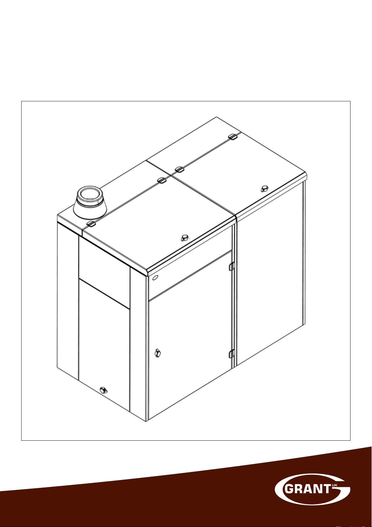
Grant External Vecta
4-16kW Condensing Wood Pellet Boiler and Side
Pellet Store
Installation and Servicing Instructions
UK | DOC 0104 | Rev 1.1 | March 2017
Page 2

Important Note for Installers
This manual is intended to guide Installers who have completed the
Grant Wood Pellet Boiler Installer training course on the installation,
commissioning and servicing of the Grant Vecta Condensing Wood
Pellet Boiler.
A separate manual is available to guide users in the operation of the
boiler.
Special Text Formats
The following special text formats are used in this manual for the
purposes listed below:
!
Warning of possible human injury as a consequence of not
following the instructions in the warning.
!
Caution concerning likely damage to equipment or tools as a
consequence of not following the instructions in the caution.
!
Used for emphasis or information not directly concerned with
the surrounding tex t but of importance to the reader.
WARNING
CAUTION
NOTE
GRANT ENGINEERING (UK) LIMITED
Hopton House, Hopton Industrial Estate, Devizes, Wiltshire, SN10 2EU
Tel: +44 (0)1380 736920 Fax: +44 (0)1380 736991
Email: [email protected] www.grantuk.com
This manual is accurate at the date of printing but will be superseded and should be disregarded if specifications and/or appearances
are changed in the interests of continued product improvement. However, no responsibility of any kind for any injury, death, loss, damage
or delay however caused resulting from the use of this manual can be accepted by Grant Engineering (UK) Limited, the author or others
involved in its publication.
All goods sold are subject to our official Conditions of Sale, a copy of which may be obtained on application.
© Grant Engineering (UK) Limited 2017. No part of this manual may be reproduced by any means without prior written consent.
Page 3

Contents
1 Introduction 4
1.1 How the Condensing Wood Pellet Boiler Operates 5
1.2 Boiler Description 5
1.3 Access 5
1.4 Flue System 5
1.5 Boiler Components 6
1.6 Logo Indicator 7
1.7 Boiler Cleaning and Servicing 7
2 Technical Data 8
2.1 Technical Specifications 8
2.2 Burner Settings 9
2.3 Flue Gas Analysis 9
2.4 Clearances and Dimensions 9
3 Pellet Specification 11
3.1 Pellet Specification 11
3.2 Biomass Suppliers List 11
4 Installation Information 12
4.1 Boiler Location 12
4.2 Regulations 12
4.3 Heating System 12
4.4 Pipework Materials 13
4.5 Connections 13
4.6 Wash System 14
4.7 Before you Commission 14
4.8 Completion 14
4.9 ‘Meter Ready’ Installations 14
5 Condensate Disposal 16
5.1 General Requirements 16
5.2 Connections 16
5.3 Pipework 16
5.4 External Pipework 16
5.5 Condensate Trap 17
5.6 Inspection and Cleaning of Trap 17
6 Sealed Systems 18
6.1 Sealed System Requirements 18
6.2 Filling the Sealed System 19
6.3 Venting the Pump 19
6.4 Pressure Relief (Safety) Valve Operation 19
7 Flue System and Air Supply 20
7.1 Air Supply 20
7.2 Flue Terminal Position and Clearances 20
7.3 Flue System Specification 21
7.4 Flue System Assembly 22
7.5 Flue Testing 23
7.6 Flue Notice Plate 23
7.7 Typical Flue Systems 24
7.8 Flue System Component Dimensions 27
7.9 Flue System Components 28
8 Electrical 30
8.1 General Requirements 30
8.2 Boiler Electrical Connections 30
8.3 Remote Grant Logo Indicator Connections 31
8.4 Connecting the Power Supply 31
8.5 Heating System Controls 31
8.6 Frost Protection 31
8.7 S-plan 32
8.8 Y-plan 32
8.9 Boiler Wiring Diagram 33
9 Boiler Operation 34
9.1 General 34
9.2 Modulation 34
9.3 Automatic Cleaning 35
9.4 Boiler Control Panel 36
9.5 Boiler Setpoint Temperature 37
9.6 Service Menu (including Parameter Menu) 37
9.7 Parameter Menu 38
9.8 Boiler Operating Sequence 40
9.9 Boiler Operation Flow Chart 41
10 Side Pellet Store 42
10.1 General 42
10.2 Operation 42
10.3 Installation 43
10.4 Electrical Connections 46
10.5 Commissioning the Side Store 47
11 Commissioning 48
11.1 Equipment Required 48
11.2 Preliminary Inspection 48
11.3 Boiler 48
11.4 Hopper Lid Cut-out Switch 51
11.5 Control Settings 51
11.6 Priming the Pellet Feed Auger 51
11.7 Lighting the Boiler 51
11.8 Combustion Chamber Draught 52
11.9 Flue Gas Analysis 52
11.10 Customer Handover 52
11.11 Commissioning Report Form 52
11.12 Commissioning Check List 53
12 Servicing 54
12.1 General 54
12.2 Checks Before Servicing 54
12.3 Heating System 54
12.4 Flue System 55
12.5 Combustion Ventilation 55
12.6 Boiler 55
12.7 Burner 58
12.8 Ignition Element 59
12.9 Condensate Disposal System 60
12.10 Boiler Settings 60
12.11 Hopper Lid Cut-out Switch 60
12.12 Combustion Checks 60
13 Fault Finding 61
13.1 Fault Codes 61
13.2 Fault Details 62
14 Spare Parts 64
15 The Clean Air Act 1993 and 66
Smoke Control Areas
16 Declaration of Conformity 67
17 Health and Safety Information 68
18 Disposal and Recycling 69
19 Guarantee 70
Contents Page 3
Page 4
1 Introduction
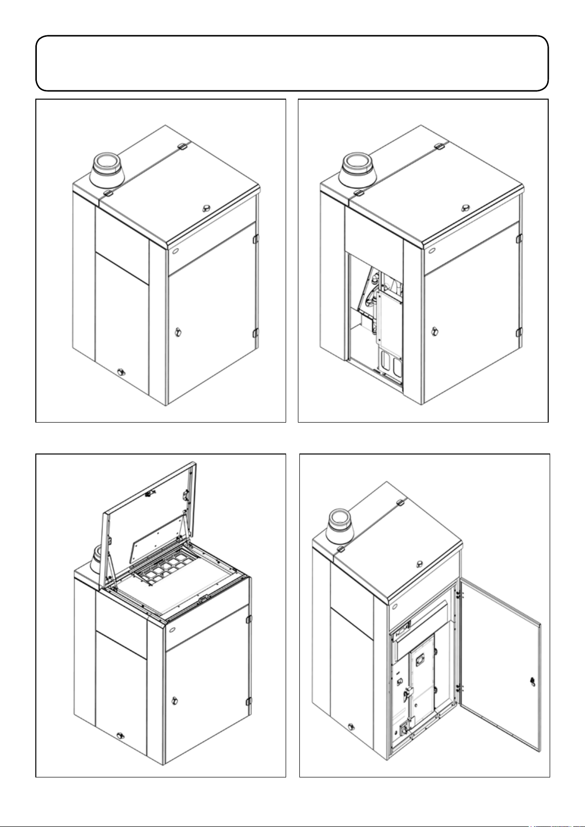
Figure 1-1: Front/left side view of boiler
Figure 1-2: Front/left side view of boiler - side access panel removed
Figure 1-3: Front/left side view of boiler - top hooper lid open
Figure 1-4: Front/left side view of boiler - hinged door open
Section 1: IntroductionPage 4
Page 5

1.1 How the Condensing Wood Pellet Boiler Operates
During the combustion process, hydrogen and oxygen combine to
produce heat and water vapour. The water vapour produced is in the
form of superheated steam in the heat exchanger. This superheated
steam contains sensible heat (available heat) and latent (heat locked
up in the flue gas). A conventional boiler cannot recover any of the
latent heat and this energy is lost to the atmosphere through the flue.
The Grant External Vecta contains a unique extra (secondary)
condensing heat exchanger which has been designed to capture
some of this lost heat energy that would otherwise be lost, so it
maintains extremely high efficiencies.
It does this by cooling the flue gases to their dew point (below 55°C)
thus extracting more sensible heat.
The boiler has been independently tested to BS EN 303-5:2012
and BS EN 12809:2001+A1:2004 and will achieve the following net
efficiencies when both the boiler and system are correctly set:
Operating Condition Full load efficiency Par t load efficiency
Condensing 101.5% 97.5%
To ensure maximum efficiency from the Grant External Vecta boiler,
the boiler return temperature should be 55°C or less (but NOT less
than 40°C) at maximum operating temperature. This will enable
the latent heat to be condensed out of the flue gases. The boiler is
capable of a maximum flow temperature of 80°C.
To achieve the required return temperature (55°C or less), it is
recommended that the heating system is designed and balanced
to operate with a temperature differential of 20°C between flow
and return. The use of modulating circulating pumps (now widely
available) and effective control systems should be considered.
The Grant External Vecta condensing wood pellet boiler will still
operate at extremely high efficiencies even when not in condensing
mode and are therefore suitable for fitting to an existing heating
system without alteration to the radiator sizes.
1.3 Access
The External Vecta wood pellet boiler enclosure is fitted with the
following means of access:
• A hinged door (with lockable door catch*) at the front - for
access to the boiler for routine cleaning (emptying the ash pan)
and access to boiler/burner controls.
• A hinged top hopper lid (with lockable door catch*) - to allow
pellets to be tipped into the hopper by the user and for access to
the top of the boiler for commissioning and servicing.
• A removable side access panel (with lockable door catch*) on
the left hand side - to allow access to the electrical wiring/PCB
enclosure, photocell ignition heater element, etc., and also the
water and condensate connections.
* These door catches can be fitted with a small padlock (not supplied)
if required.
To unlock and open any of the above, unlock/remove the padlock (if
fitted). Rotate the knob of the catch clockwise to unlatch and open the
front door, top hopper lid or side access panel.
Close and lock the door, lid or panel using the reverse of the above
procedure.
1.4 Flue System
The Grant External Vecta wood pellet boiler must be connected to a
conventional flue system.
!
The ONLY flue suitable for use with the Grant Vecta wood pellet
boilers is the Grant ‘Biomass’ conventional flue system. This
is a 125mm (5”) diameter twin wall insulated, powder coated
stainless steel flue system. Refer to Section 7 for details.
NOTE
1.2 Boiler Description
Grant External Vecta wood Pellet boilers have an insulated
weatherproof enclosure made of galvanised steel with a powder
coated finish, and are designed for external installation, either against
a wall or free standing some distance away from the proper ty, as
required.
The boiler is suitable for use on a sealed or open vented central
heating system. When commissioned and set correctly, the Grant
External Vecta wood pellet boiler will operate automatically, using a
typical heating control system.
The boilers are not designed specifically for operation on a system
with a buffer tank/ thermal store, however when used on such a
system there is no effect on the boiler performance.
Refer to Section 4 for boiler installation.
Section 1: Introduction Page 5
Page 6
1.5 Boiler Components
1.5.1 Burner
The Grant External Vecta boiler uses a drop feed t ype burner with
modulated heat output. The burner output is determined by varying
the feed and pause time of the pellet feed auger supplying pellets to
the burner. Refer to Section 9 for details of burner operation.
The burner is supplied factory-fitted in the boiler and is equipped with
a self-cleaning device to prevent a build-up of ash and clinker in the
burner brazier.
The boiler is supplied with the control parameters factory set to
default settings.
During commissioning these control parameters should be checked
to ensure they are correct. Refer to Section 11.5 for details.
1.5.2 Heat exchangers
The Grant External Vecta 4-16 condensing boiler is supplied with
a combined primary and secondary heat exchanger. Both heat
exchangers are equipped with a self-cleaning system.
1.5.3 Boiler controls
!
After the burner has been switched off (either manually by the
ON/STANDBY switch on the control panel, or automatically by
the boiler control system, or the heating system controls) the
burner needs to burn-down the remaining pellets in the brazier.
Do not open the front combustion chamber access door until
the burner display reads ‘Standby’.
The Setpoint temperature of the boiler is user adjustable via the boiler
control panel - refer to Section 9.4 for details.
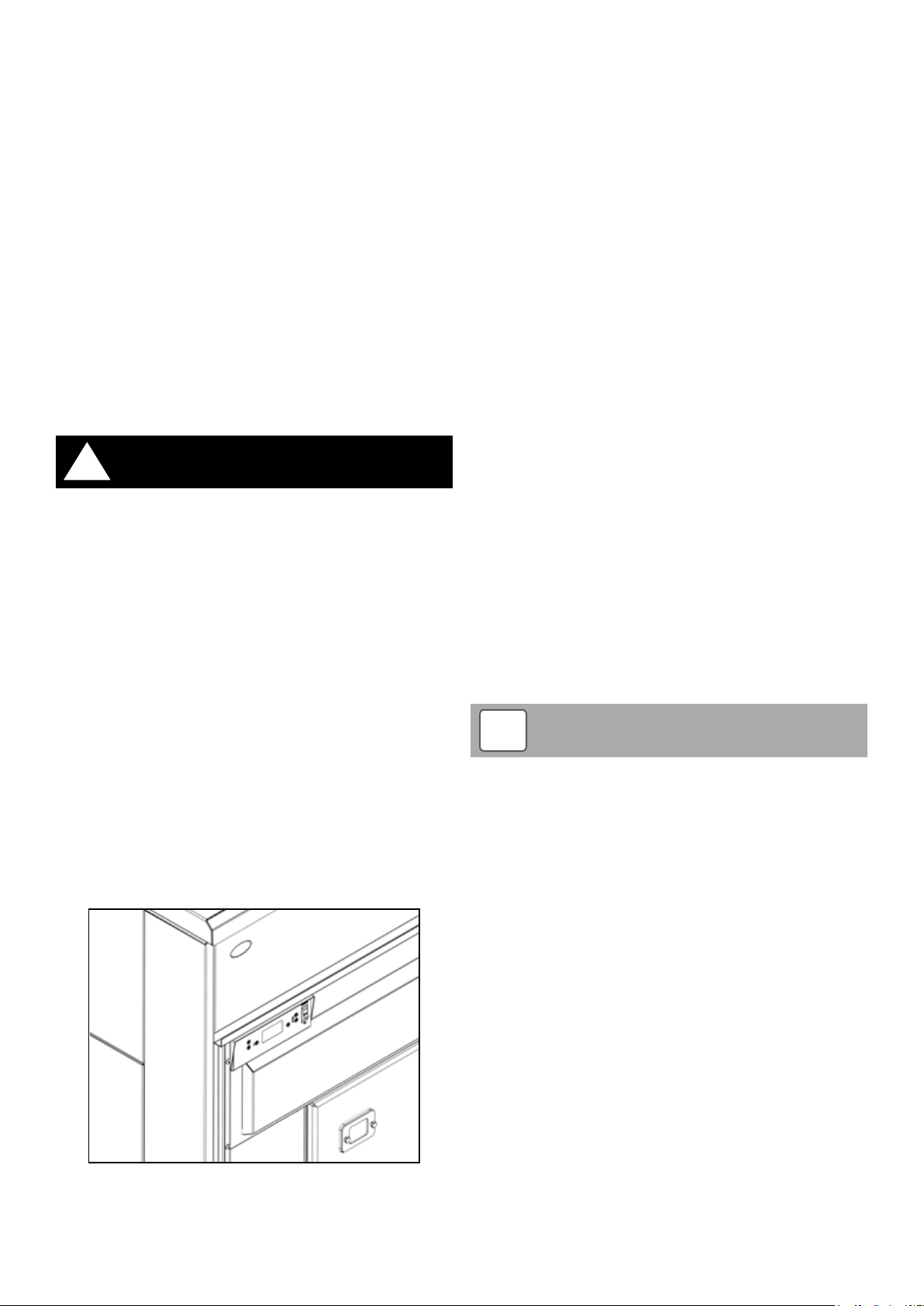
The boiler control panel is located at the upper left corner of the boiler
(behind the hinged front door of the boiler). Refer to Figure 1-5. To
unlock/open the front door of the boiler, first unlock and remove the
padlock (if fitted). Rotate the knob of the catch clockwise to unlatch
and open the front door.
This control panel includes the following items (refer to Section 9.4 for
further details of the control panel functions):
• ‘ON/STANDBY’ switch – to switch the burner off when required,
by interrupting the switched live supply to the burner. This switch
does not isolate the electrical supply to the burner.
• LCD screen – to display the boiler operating condition and (when
necessary) a fault code
• Boiler control setting buttons – Refer to Section 9 for boiler
control system operation and setting.
WARNING
overheat thermostat bulb is situated in the top front left corner of the
boiler, along with the boiler control thermistor sensor. Refer to Section
11.3 for the location of the bulb and sensor.
This overheat thermostat allows the boilers to be used on a sealed
central heating system and will automatically switch off the boiler if the
pre-set temperature of 100°C is exceeded.
1.5.4 Boiler Pellet Hopper
The Grant External Vecta boiler has an integral pellet hopper with a
capacity of 80kg. This is accessed by lifting the hinged hopper lid on
the top of the boiler so that pellets can be tipped into the hopper by
the user.
The hopper is fitted with a contents switch. This detects when the
level of pellets in the hopper falls to a pre-set minimum value. At this
point the LCD screen will flash and display the ‘Fuel Low Warning’
message. The Grant logo indicator will also flash slowly to indicate the
pellet level has fallen to the pre-set minimum. Refer to Section 1.5.
As soon as this happens the hopper should be topped up with more
pellets. This will automatically cancel the flashing Grant logo and
the flashing ‘Fuel Low Warning’ message on the control panel LCD
screen.
If the pellet hopper is not topped up at this point, the boiler
will continue to operate for a short period before the burner is
automatically stopped. The Grant logo will continue to flash slowly,
with the flashing ‘Low Fuel Warning’ message on the control panel
LCD screen, to indicate the lack of pellets in the boiler.
If this happens, simply top up the hopper with more pellets. A
minimum of 20kg of pellets will operate the contents switch and
automatically re-start the burner (as long as there is a demand for the
boiler to run).
To top up the hopper, first set the ‘ON/STANDBY’ switch to ‘STANDBY’
and wait for the boiler to stop. Then open the hinged hopper lid (on
the top of the boiler) and tip in the required amount of pellets. Then
close the hopper lid and reset the ‘ON/STANDBY’ switch to ‘ON’.
Whilst topping up with pellets, ensure that no foreign debris enters the
hopper.
!
The hinged hopper lid is fitted with a safety cut-out switch and
MUST BE CLOSED for the boiler to operate. If the lid is opened
for longer than 5 seconds, whilst the boiler is operating, the
burner will be automatically stopped. Closing the hopper
lid resets the cut-out switch and the boiler will restart. Refer
to Section 11.4 for details of the hopper lid cut-out switch
operation.
NOTE
Figure 1-5: Boiler control panel
The boiler also includes an overheat thermostat – located at the
bottom left corner of the boiler (inside the front door) with the reset
button under the removable plastic cap. Refer to Figure 11-3. The
1.5.5 Frost Protection
The Grant External Vecta wood pellet boiler is supplied with a factoryfitted frost protection thermostat. This is pre-set to operate when the
air temperature falls to 2°C.
This frost thermostat is located inside the PCB enclosure and wired to
the boiler terminal block. For details of the frost thermostat electrical
connections, refer to Section 8.6.
Section 1: IntroductionPage 6
Page 7

1.5.6 Side Pellet Store
An optional separate 140kg capacity pellet store is available to
increase the pellet storage for the External Vecta boiler. This side
pellet store is the same external design as the External Vecta boiler
and is designed to be located at the right hand side of the boiler only.
It incorporates an auger to automatically transfer pellets from the side
pellet store to the boiler pellet store when activated by the contents
switch. Refer to Section 10 for full details of the installation and
operation of the side pellet store.
!
This side pellet store CANNOT be installed on the lef t hand
side of the External Vecta boiler.
NOTE
1.6 Logo Indicator
The illuminated Grant logo indicator, supplied with the boiler, should
be mounted on a standard electrical back box (either recessed or
surface mounted) in a convenient and visible position within the
property. Refer to Section 8 for electrical connection details.
The Logo Indicator has been designed to assist the user by clearly
indicating the following boiler conditions:
Logo illuminated (low brightness):
Indicates the following:
• The electrical power supply is connected to the boiler and it is
switched on
• There is no demand from the heating system controls for the
boiler to operate
AND/OR
• The ON/STANDBY switch on the boiler control panel is set to OFF
This does not indicate that the boiler is operating or that the burner is
firing. Refer to Section 9.
Logo illuminated (high brightness):
Indicates the following:
• The electrical power supply is connected to the boiler and it is
switched on
• There is a demand from the heating system controls for the boiler
to operate
AND
• The ON/STANDBY switch on the boiler control panel is set to ON
This does not necessarily indicate that the boiler is operating or that
the burner is firing. Refer to Section 9.
1.7 Boiler Cleaning and Servicing
The Grant External Vecta wood pellet boiler is equipped with an
automatic cleaning system for the burner brazier and both heat
exchangers.
The ash pan (located inside the combustion chamber) MUST be
periodically emptied by the user. This simple task must be carried out
when indicated by the Grant logo Indicator flashing (fast flash). Refer
to Section 1.6.
The boiler is fitted with a hinged front door with a lockable door catch.
This door must be opened to gain access to the ash pan for the
periodic cleaning of the boiler. Refer to Section 12.6.5.
To open the door, first unlock and remove the padlock (if fitted).
Rotate the knob of the catch clockwise to unlatch and fully open the
front door.
A multi-purpose tool is supplied with the boiler for ser vicing and
cleaning. This is used for the following functions:
• As the door catch handle – required to open the combustion
chamber door
• As the ash pan carrying handle*
• To open the brazier catch
• To remove the brazier front plate, the brazier base plate and the
brazier cotter pin
The multi-purpose tool is hung on a hook located on the panel to the
left of the combustion chamber door. Always replace the tool back on
this hook af ter use to ensure it is available when next required.
*An ash pan carrying handle is also supplied with the boiler. This must
be used in conjunction with the multi-purpose tool, to suppor t the
opposite end of the ash pan, when removing it from the boiler. Refer to
Section 12.6.5. The ash pan, once removed can only be replaced one
way. If replaced incorrectly the combustion door cannot be closed.
!
Whilst removing the ash from the boiler, care must be taken to
avoid contact with hot surfaces. Always wait for the boiler to cool
down before opening the combustion chamber door and removing
the ash pan.
The boiler MUST be serviced either ANNUALLY or when the
‘Service’ message is displayed on the control panel LCD
screen, whichever comes FIRST.
Servicing should only be carried out by a Grant Trained Installer and
details of each service should be recorded in the Service Log in the
back of the User Guide.
CAUTION
Logo flashing (slow flash):
Indicates a low pellet level – when the minimum level of pellets in the
pellet hopper has been reached. Top up the pellet hopper in the boiler
without delay. Refer to Sections 1.4.4 and 3.
If a side pellet store is installed, also top up this store at the same
time. Refer to Section 10.
Logo flashing (fast flash):
Indicates ash pan needs empt ying – empty ash pan without delay.
Refer to Section 1.7.
Section 1: Introduction Page 7
Page 8

2 Technical Data
2.1 Technical Specifications
Units 4-16
Maximum heat output
Minimum heat output
Flow connection mm 22
Return connection mm 22
Mains water connection mm 15
Water content litres 35
Minimum flow rate litres/hour 690
Waterside resistance ∆T=10°C mbar 27
Waterside resistance ∆T=20°C mbar 9
Maximum mains inlet water pressure kPa 800 (8 bar)
Minimum mains inlet water pressure kPa 100 (1 bar)
Condensate connection - 1¼ BSP (female)
Combustion chamber draught requirement mbar 0.75 to 1.25
Maximum static head metres 28
Minimum circulating head metres 1
Boiler temperature set point range °C 55 to 75
Boiler temperature cut out point °C 80
Minimum return temperature °C 40
Water system overheat cut-out temperature °C 100
Electrical supply - ~230V 1ph 50 Hz 5A fused
Maximum operating pressure - sealed system bar 2.0
Maximum operating pressure - open system bar 2.0
Maximum operating pressure - pressure relief valve bar 2.5
Flue length - minimum metres 1.4
Flue length - maximum metres 12.0
Ignition element rating Watts 283
Efficiency - full load (condensing)* % 101.5
Efficiency - par t load (condensing)* % 97.5
Combustion gas temperature - maximum output °C 56
Combustion gas temperature - minimum output °C 47
Combustion gas mass flow rate - maximum output m³/h 66
Combustion gas mass flow rate - minimum output m³/h 26.35
Safety charge pipe thermostat cut-out temperature °C 90
Total boiler starting current Amps 2.5
Total boiler running current Amps 0.45
Weight of boiler - including water content and full pellet hopper kg 380
Weight of boiler - excluding water content and empty pellet hopper kg 265
Integral pellet hopper capacity kg 80
Weight of side store (optional) - full pellet hopper kg 220
Weight of side store (optional) - empty pellet hopper kg 80
Side pellet store hopper capacity (optional) kg 140
* Refer to Section 1.1
kW
Btu/h
kW
Btu/h
16.2
55,300
4.5
15,300
Section 2: Technical DataPage 8
Page 9
2.2 Burner Settings
868
MAX flame MIN flame
Model
4-16 1.7 sec 3.0 sec
Notes
*Heat input is based on a calorific value of 4.81 kWh/kg.
Heat input and output data given above is approximate only.
All burner settings must be checked as part of commissioning and ser vicing. Refer to Section 9.6 for full details of the burner settings and how to access, check
and, where necessary, how to adjust them.
Burner setting
TIME
LOAD
MAX
TIME
PAUSE
MAX
Heat
output
kW
(Btu/h)
16.2
(55,300)
Heat input
kW
(Btu/h)
17.2
(58,700)
Full
eff.
101.5 3.53
Input
kg/hr*
Draught CO
mbar
(in.wg)
0.75 - 1.25
(0.30 - 0.5)
2
%
8-12 14.0 sec
Burner setting Heat output
TIME PAUSE
MIN
kW
(Btu/h)
4.5
(15,400)
2.3 Flue Gas Analysis
As part of both the commissioning and servicing procedures, the CO2
content of the flue gases must be checked.
There is no combustion test point on the boiler. A test point (and flue
inspection hatch) is provided in the Inspection Pipe (product code:
WPBOM/IP) that MUST be fitted to the boiler flue outlet.
To gain access to this test point, the circular outer cover must be
removed. To do this, turn the knob in the centre of the outer cover
approximately one turn anticlockwise and pull the cover away from
the inspection pipe. The combustion test point is located immediately
below the flue inspection hatch. Refer to Figure 11-11.
Unscrew and remove the test point screw to insert the combustion
analyser probe.
Replace the outer cover using the reverse procedure, turning the knob
approximately one turn clockwise to secure the cover in place.
!
Always replace the test point screw and outer access cover
following combustion testing. Do not overtighten test point
screw.
Use only a calibrated flue gas analyser with a ‘Wood Pellet’ fuel
setting. Setting the fuel to any thing other than wood pellets will
give an incorrect reading.
To ensure correct combustion, the burner settings given in the
table (in Section 2.2) must NOT be changed unless instructed
to do so by Grant UK.
NOTE
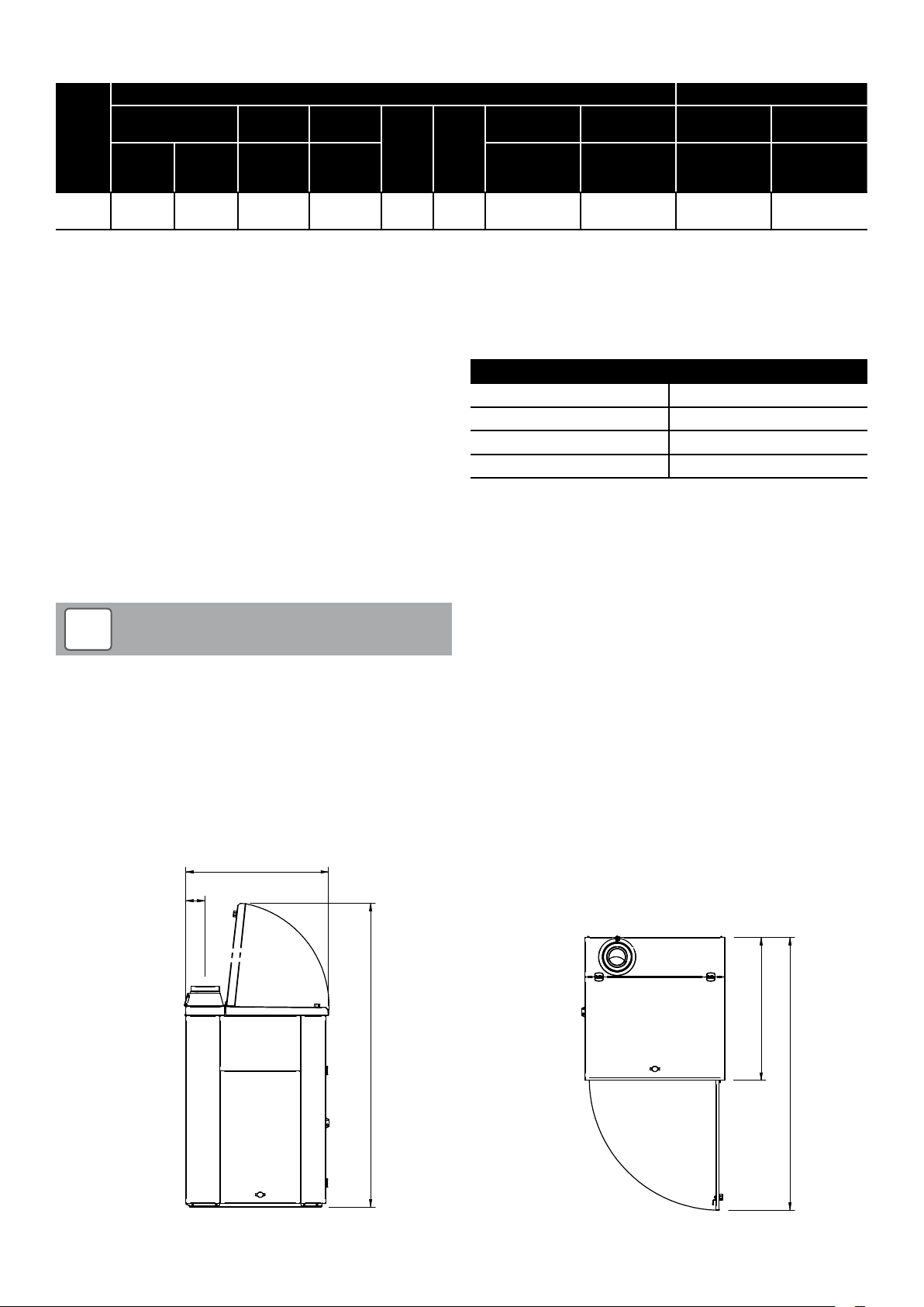
2.4 Clearances and Dimensions
2.4.1 Clearances
Clearances
Right hand side 150 mm
Left hand side 400 mm
Front 850 mm
Rear 30 mm
2.4.2 Dimensions
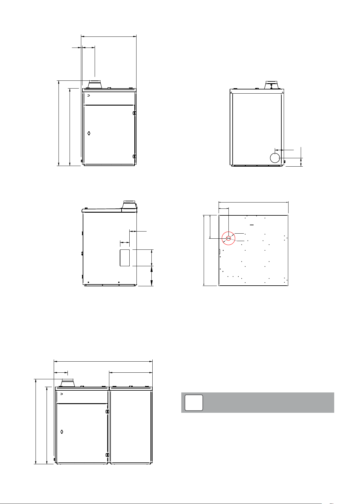
Refer to Figures 2-1 to 2-7.
868
119
868
1843
1657
Figure 2-1: Boiler dimensions - left side view
Figure 2-2: Boiler dimensions - top view
Section 2: Technical Data Page 9
Page 10
868
870
119
1843
868870
LEFT SIDE
VIEW
1843
1657
868
TOP
VIEW
868870
141
132
1216
FRONT
VIEW
LEFT SIDE
VIEW
20
1340
196 119
1843
TOP
VIEW
868
119
20
196
1340
1216
141
Figure 2-3: Boiler dimensions - front view Figure 2-4: Boiler dimensions - rear view
793
112
132
Figure 2-5: Boiler dimensions - right side view
1552
216 682
150
114
265
804
O
150
O
50
260312
Figure 2-6: Boiler dimensions - top view of base
!
NOTE
1341
1216
Figure 2-7: Boiler and side store dimensions - front view
When the side store lid is open, it is the same height as the
boiler lid open, i.e. 1,843 mm.
Section 2: Technical DataPage 10
Page 11
3 Pellet Specification
3.1 Pellet Specification
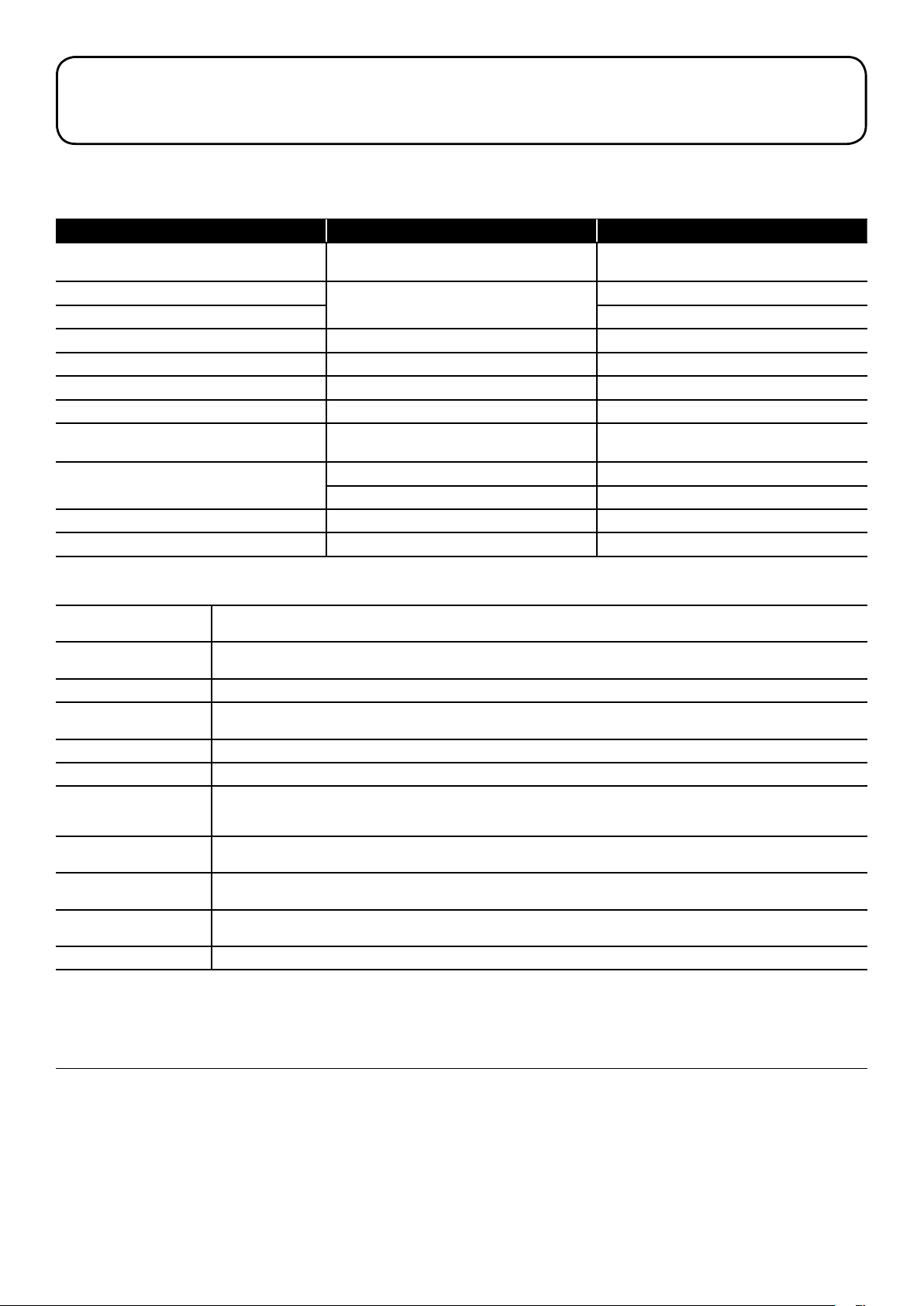
Grant Vecta boilers are designed to ONLY run on EN Plus Grade A1 wood pellets that comply with BS EN ISO 17225-2:2014 and meet the
following criteria. Failure to use approved pellets will invalidate the product guarantee.
Proper ty class Unit Limits as per BS EN ISO 17225-2
Origin and source
Diameter (D)
Length (L) 6 ± 1
mm
Moisture (M) w-% ≤ 10
Ash (A) w-% dry ≤ 0.7
Mechanical durability (DU) w-% ≥ 97.5
b
Fines (F)
Additivies
c
Net calorific value (Q)
Bulk density (BD)
d
w-% ≤ 1.0
w-%
MJ/kg or ≥ 16.5
kWh/kg ≥ 4.6
3
kg/m
Chlorine (Cl) w-% dry ≤ 0.02
1.13 Stemwood
1.2.1 Chemically treated wood residues
3.15 < L ≤ 40
≤ 2
Type and amount to be stated
≥ 600
a
The following terms are commonly used when describing the properties of wood pellets:
Additives
Ash
Average length To provide a predictable flow of fuel into the burner, the recommended length of a pellet is between 3.15 and 40mm.
Bulk density
Chlorine High levels of chlorine in the flue gases emissions can give rise to corrosion.
Diameter The most common diameter is 6mm with some 8mm also available. This boiler is designed for 6mm only.
Fines
Mechanical durability
Moisture content
Net calorific valve
Nitrogen and sulphur High levels of Nitrogen and Sulphur in the flue gases emissions can give rise to corrosion.
Footnotes
a
Negligible levels of glue, grease and other timber production additives used in sawmills during production of timber and timber product from virgin wood are
acceptable, if all chemical parameters of the pellets are clearly within the limits and/or concentrations are too small to be concerned with.
b
At factory gate in bulk transport (at time of loading) and in small (up to 20kg) and big bags (at time of packing) or when delivering to end-user.
c
Type of additives to aid production, deliver y or combustion.
d
It is recommended actual value of bulk density to be stated.
Additives are used to improve the stability of the pellets. If manufactured correctly, and of a suf ficiently low moisture content,
quality pellets will require no additives.
Ash represents the non-combustible content of the pellet. Higher ash content reduces the calorific value of the pellet and requires
the appliance to be cleaned more frequently.
Bulk density is the ratio bet ween the weight of the pellet and the amount of space they take up. A good quality pellet will have a
density of 650 kg/m
3
.
Pellets are made from compressed wood. As pellets rub together they can break down slightly, producing dust or fines. Too
many fines indicate a poor qualit y pellet and can impede pellet flow in addition to causing dust problems when delivering and
storing the pellets.
This is a measure of how stable the pellet is and how likely it is to produce fines from normal handling.
A high durability percentage is an indicator of a go od quality pellet.
Moisture affects the calorific value of the pellet. Low moisture content guarante es constant and predictable combustion
efficiency. Higher moisture contents can result in pellet breakdown.
This is the useful energy contained in a kilogram of fuel. This value is affected by the amount of non-combustible materials (ash)
and the moisture content of the pellet. Typical values range from 4.8 kWh/kg to 5.2 kWh/kg.
3.2 Biomass Suppliers List
The Biomass Suppliers List (BSL) is a list of suppliers of wood fuel who have been accredited as demonstrating that their fuel meets the
sustainability criteria required under the RHI.
Recipients of the Domestic RHI will be obliged to source their fuel from suppliers on the BSL unless they are supplying themselves.
To find an approved supplier in your area go to w ww.biomass-suppliers-list.service.gov.uk/find-a-fuel
Section 3: Pellet Specification Page 11
Page 12

4 Installation Information
4.1 Boiler Location
The Grant External Vecta wood pellet boiler must be installed
externally, either against the building or ‘free standing’ some distance
away from the building. Refer to Section 7.7.
If the ‘free standing’ option is chosen, then the boiler flue system must
be at least 2,300mm away from any buildings or structure that are
higher than the flue outlet. Refer to Section 7.7.
If this distance cannot be achieved, then the External Vecta boiler will
have to be located with the back of the enclosure close to or against
the building and the flue system extended such that the terminal is
above the eaves of the roof. Refer to Section 7.7.
The Grant External Vecta boiler must be positioned such that
sufficient clearance is provided for maintenance, servicing and filling
the pellet hopper. In the par ticular, the following minimum clearances
are required around the External Vecta:
• Front: 850mm (to open the hinged front door to commission or
service the boiler)
• Left hand side: 400mm (to access the PCB, water and
condensate connections)
• Right hand side: 150mm (to access pellet hopper for filling with
pellets)
• Rear: 30mm
The Grant External Vecta boiler must stand on a solid, level, noncombustible surface capable of supporting both the weight of the
boiler when full of water and the pellet hopper is full of pellets. Refer to
Section 2 for weights.
Grant recommends a prepared concrete standing (at least 150mm
thick) with a smooth finish on the top ex tending beyond the enclosure
base at least 100mm all around. Refer to Section 2.4 for boiler
dimensions.
4.2 Regulations
Installation of a Grant Vecta wood pellet boiler must be in accordance
with the following:
• National Building Regulations and any local Byelaws.
• Model Byelaws and the Water Supply Regulations.
The installation should also be in accordance with the latest edition of
the following standards and codes of Practice:
• BS 715:2005 Metal flue pipes, fittings, terminals and accessories.
• BS EN 12828:2003. Heating systems in buildings. Design for
water-based heating systems
• BS EN 12831:2003. Heating systems in buildings. Method for
calculation of the design heat load.
• BS EN 14336: 2004. Heating systems in buildings. Installation
and commissioning of water based heating systems.
• BS 7593:2006 Code of Practice for treatment of water in heating
systems.
• BS 7671:2008 Requirements for electrical installations, IET wiring
regulations.
• ONORM M7137 standard should be used as a guideline for DIY
bulk storage units.
4.3 Heating System
!
Before star ting any work on the boiler or fuel supply please
read the Health & Safet y information given in Section 17.
To achieve the ma ximum efficiency possible from the Grant Vecta
condensing wood pellet boiler, the heating system should be
designed to the following parameters:
Radiators
• Flow temperature 70°C
• Return temperature 50°C
• Differential 20°C
Size the radiators using a mean water temperature of 60°C.
Design system controls with programmable room thermostats, or
use weather compensating controls, to maintain return temperatures
below 55°C.
!
The boiler should not be allowed to operate with a return
temperature of less than 40°C when the system is up to
operating temperature.
The use of a pipe thermostat is recommended to control the return
water temperature when using weather compensating controls.
Underfloor Heating
•Flowtemperature50°C
•Returntemperature40°C
•Differential10°C
In underfloor systems it is essential that the return temperature must
be maintained at or above 40°C to prevent internal corrosion of the
boiler water ‘primary’ jacket.
Open Vented Systems
!
The presence of ‘pumping over’ in an open vented heating
system connected to the Grant Vecta boiler will invalidate the
product guarantee.
Open vented systems must be correctly designed and installed.
The open safety vent pipe must be positioned to prevent ‘pumping
over’ (i.e. the discharge of water from the open safety vent pipe into
the feed and expansion cistern under the pressure created by the
circulator).
For detailed information on the correct design of open vented heating
systems, and the correct location of the open safety vent pipe, refer to
the CIBSE Domestic Heating Design Guide.
WARNING
NOTE
NOTE
!
Failure to install and commission the appliance correctly will
invalidate the boiler guarantee.
NOTE
Section 4: Installation InformationPage 12
Page 13
4.4 Pipework Materials
The Grant Vecta boiler is compatible with both copper and plastic
pipe. Where plastic pipe is used it must be of the oxygen barrier
type and be the correct class (to BS 7291-1:2010) for the application
concerned.
On either sealed or open-vented systems; where plastic pipe is
used a minimum of ONE metre of copper pipe (or as per pipe
manufacturers instructions) MUST be connected between both the
boiler flow and return connections and the plastic pipe.
!
Do not connect plastic pipe directly to the boiler.
Grant does not accept any responsibility for any damage, however
caused, to plastic piping or fittings.
Sealed Systems
If plastic pipe is to be used, the installer must check with the plastic
pipe manufacturer that the pipe to be used is suitable for the
temperature and pressures concerned.
Plastic pipe must be Class S to BS 7291-1:2010.
NOTE
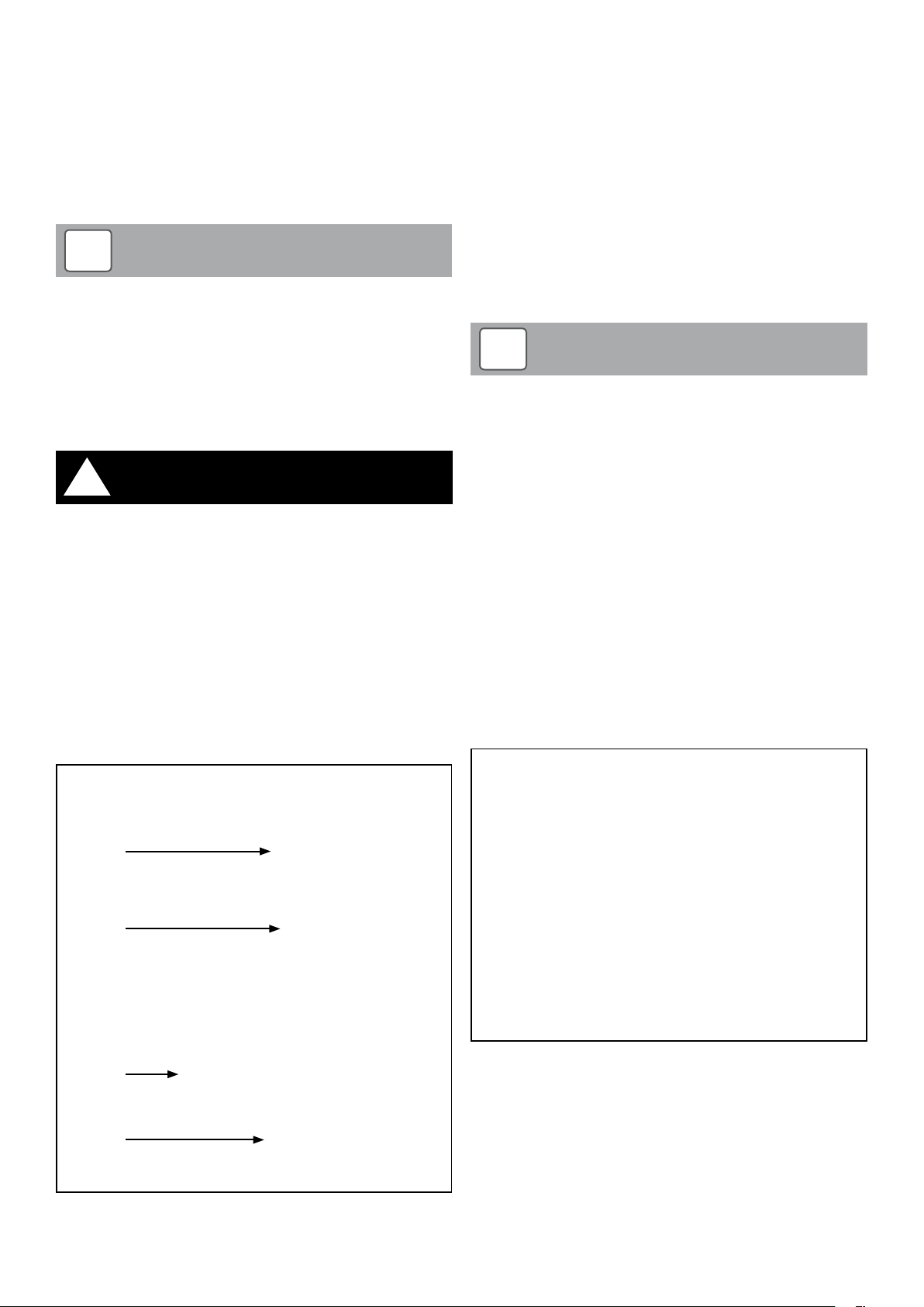
The flow and return connections are located on the left hand side of
the boiler. Refer to Figure 4-1. Both connections are supplied fitted
with 22mm Tectite elbow connectors.
Two 150mm diameter pre-cut ‘knock-out’ openings are provided for
flow and return pipes and also the condensate disposal pipe. Refer to
Figure 4-1:
• One is located in the lower left corner of the boiler back panel
• The other is located in the base of the boiler
The flow and return pipes can pass downwards and then to the rear
of the boiler, through the opening in the boiler back panel and then
through the wall and into the building.
Alternatively, if required, the flow and return pipes can pass
downwards and through the opening in the base of the boiler to pass
underground and into the house.
!
It is NOT possible to have the flow and return pipes (or
condensate pipe) passing through either the right or lef t hand
side of the boiler casing.
NOTE
!
The system MUST incorporate a low level pressure switch
to shut off power to the boiler if the system pressure drops
below 0.2 bar. A suitable low pressure switch kit is available to
purchase from Grant (product code: MPCBS63).
Underfloor Pipework
Plastic pipe may be used on underfloor floor systems where the
plastic pipe is fitted after the thermostatic mixing valve. Copper tube
must be used for at least the first metre of flow and return primary
pipework between the boiler and the underfloor mixing/blending
valves.
WARNING
4.5 Connections
4.5.1 Flow and return connections
Flow
Return
4.5.2 Condensate Connection
The boiler is supplied with the condensate trap factory-fitted. Refer
to Section 5.5. This trap is located inside the boiler casing and is
accessed by removing the side access panel on the left hand side of
the boiler. Refer to Section 1.3 for details.
Refer to Section 5 for details on the condensate disposal pipework.
4.5.3 Drain Cock
A drain cock is factory fitted to enable the draining of the boiler. This is
located at the rear of the water jacket and accessed by removing the
side access panel on the left hand side of the boiler. Refer to Figure
4-2.
To enable draining of the system, a suitable drain cock must be fitted
at the lowest point of the heating system.
Rear
opening
Base
opening
Figure 4-1: Location of flow and return connections and openings in
rear panel and base
Figure 4-2: Location of drain cock (left hand side and rear panel
removed for clarity)
Section 4: Installation Information Page 13
Page 14

4.6 Wash System
The Grant Vecta condensing boiler is supplied with an automatic
cleaning system to wash any ash build up from the tubes of the
condensing (secondary) heat exchanger.
This factory fitted wash system consists of two spray jets, mounted
on the heat exchanger access cover, connected by a manifold pipe
located on the upper side of the cover. Refer to Figure 4-3.
Figure 4-3: Location of wash system in top of boiler
This is fed with mains cold water via a solenoid valve located in the
left side of the boiler. This is connected to the manifold by a flexible
hose and isolating valve (with integral check valve). Refer to Figure
4-3.
Connect the mains water supply for the wash down system to the
15mm compression connection located at the bottom rear corner of
the left side panel.
Connect the mains water supply for the wash system to the 15mm
compression connection on the water solenoid valve. This is located
at the side of the primary heat exchanger on the left hand side of the
boiler and accessed by removing the access panel on the left hand
boiler side panel.
The appliance must not be connected to the mains water supply via a
flexible hose.
!
A minimum inlet water pressure of 100 kPa (1 bar) is required
to maintain an adequate supply for cleaning purposes. The
maximum inlet water pressure is 800 kPa (8 bar).
In hard water areas an anti-scale device should be fitted on the
cold water supply to the wash system to prevent scale build-up
in the manifold pipe and jets.
NOTE
4.7 Before you Commission
To avoid the danger of dir t and foreign matter entering the boiler the
complete heating system should be thoroughly flushed out – both
before the boiler is connected and then again after the system has
been heated and is still hot. This is especially impor tant where the
boiler is to be installed on an older system.
For optimum performance after installation, the boiler and the
associated heating system must be flushed in accordance with the
guidelines given in BS 7593:1992 ‘Treatment of water in domestic
hot water central heating systems’. This must involve the use of a
proprietary cleaner, such as Sentinel X300 (new systems), Sentinel
X400 (existing systems), or Fernox Restorer.
After cleaning, it is vitally important that all traces of the cleaner are
thoroughly flushed from the system.
For long term protection against corrosion and scale, after cleaning/
flushing a suitable inhibitor should be added to the system water,
such as Sentinel X100 or Fernox MB-1, in accordance with the
manufacturers’ instructions.
Failure to follow the above will invalidate the guarantee.
In order to provide further protection should there be a power failure
in cold weather, a combined anti-freeze and corrosion inhibitor
can be used such as Sentinel X500 or Fernox Alphi-11. Follow the
manufacturers’ instructions supplied to achieve the level of anti-freeze
protection required.
For details of the Sentinel Products visit www.sentinel-solutions.net
and for Fernox products visit www.fernox.com.
A Grant Mag-One in-line magnetic filter/s (or equivalent*)
must be fitted in the heating system pipework. This must be
installed and regularly ser viced in accordance with the filter
manufacturers’ instructions.
* As measured by gauss. The Mag-One magnetic filter has a gauss
measurement of 12000
4.8 Completion
Please ensure that the Grant Vecta Commissioning form (supplied
with the boiler) is completed in full and that it is signed by the
householder/user.
Leave the white copy with the user, retain the pink copy for your own
records, and return the yellow copy to Grant to register the installation
of the boiler.
Ensure that the user guide (supplied with the boiler) is handed over to
the householder along with this Installation and Servicing manual.
4.9 ‘Meter Ready’ Installations
Grant Vecta wood pellet boiler installations that are receiving a
Domestic Renewable Heat Incentive (RHI) payment will not usually
require a heat meter to be fitted.
However, all such domestic RHI installations must be ‘meter ready’ in
accordance with MCS requirements. Refer to the MCS Domestic RHI
Metering Guidance Document for full details.
Section 4: Installation InformationPage 14
Page 15

Figure 4-4: Water connection to wash system (via flexible hose from solenoid valve)
Section 4: Installation Information Page 15
Page 16

5 Condensate Disposal
5.1 General Requirements
When in condensing mode the Grant Vecta condensing wood
pellet boilers produce condensate from the water vapour in the flue
gases. This condensate is slightly acidic with a pH value of around
6. Provision must be made for the safe and effective disposal of this
condensate.
Condensate can be disposed using one of the following methods:
• into a soil stack – either directly or via an existing waste system
• into an gulley
All condensate disposal pipes must be fitted with a trap whether
they are connected internally or externally to a domestic waste
system/soil stack or run externally to a gully or hopper.
Every Grant Vecta boiler is supplied with a trap and this MUST
be used. Refer to Section 5.5 for trap details.
MCS Product Certification Scheme Requirements for Biomass (MCS
008) state that:
“Because of the volume of wash-down/condensate discharge, it is
NOT recommended to discharge into a purpose-made soakaway.”
5.2 Connections
Connections into a rainwater hopper, external drain or gulley should
be terminated inside the hopper/drain/ gulley below the grid level but
above the water level.
Condensate disposal pipes can be connected directly into waste/soil
systems connected to septic tanks, providing a neutraliser has been
installed.
Condensate must not be discharged into ‘grey water’ systems that
re-use water used in the home (not including water from toilets).
It should be noted that connection of a condensate pipe to the drain
may be subject to local Building Control.
!
When using a condensate pump and holding tank, the Boiler
control set ting for ‘Clean Boiler’ (time between boiler cleaning
operations) must not be set less than 480 minutes. Changing
this setting could result in a more frequent wash down of the
boiler which could exceed the capabilities of the tank and
condensate pump.
The ‘Max Cleaning Time’’ (maximum time boiler cleaning is in
operation) is factory set at 60 seconds.
Refer to Section 9 for further details on boiler control settings.
WARNING
5.4 External Pipework
Ideally, external pipework, or pipework in unheated areas, should be
avoided. If unavoidable, external pipework should be kept as short
as possible (less than 3 metres) and 38mm (1½”) waste pipe used to
minimise the risk of ice blocking the pipe in freezing conditions.
The number of bends, fitting and joints on external pipes should be
kept to a minimum to reduce the risk of trapping condensate.
5.3 Pipework
Condensate disposal pipework must be plastic. Copper or steel
pipe is not suitable and must NOT be used.
All condensate disposal pipes connected to a Grant Vecta boiler must
have a minimum ‘nominal’ diameter of 32mm (1 ¼”) plastic pipe.
Condensate disposal pipes should be kept as short as possible and
the number of bends kept to a minimum.
Pipes should be adequately fixed to prevent sagging, i.e. at no more
than 0.5 metre intervals.
Condensate disposal pipes must be fitted with a fall (away from the
boiler) of at least 2.5° (≈45mm fall per metre run).
!
Where it is not possible for the pipe to fall towards the point of
discharge – either into a waste system or to a gulley, it will be
necessary to use a condensate pump.
When using a condensate pump with a Grant Vecta boiler, a
condensate holding tank of at least 40 litres is required. This is
to ensure that when the boiler cleaning cycle has operated the
holding tank can collect the total volume of the water used in the
wash system and the condensate pump can then discharge the
waste water effectively.
A boiler interlock should be fitted to shut off the boiler in the
event of a malfunction of the condensate pump. This must be
located indoors.
NOTE
Section 5: Condensate DisposalPage 16
Page 17

5.5 Condensate Trap
The boiler is supplied with a factory-fitted condensate trap. This trap is
located inside the boiler casing and is accessed by removing the side
access panel on the left hand side of the boiler.
!
Only this trap must be used with the Vecta boiler. No alternative
trap should be used as it will not give the required depth of
water seal. The trap is designed to be fitted as supplied, i.e.
inside the boiler casing on the left hand side only.
Two 150mm diameter pre-cut ‘knock-out’ openings are provided in the
boiler enclosure for the condensate disposal pipe (and also the flow
and return pipes). Refer to Figure 4-1.
• One is located in the lower left corner of the boiler back panel (as
viewed from the front)
• The other is located in the base of the boiler
The condensate disposal pipe can pass downwards from the trap
outlet and then to the rear of the boiler, through the opening in
the boiler back panel. It can then run either to an external gulley
or external soil pipe or it could pass through the wall and into the
building to connect to an internal waste system or soil pipe.
Alternatively, if required, the condensate disposal pipe can pass
downwards from the trap outlet, through the opening in the base of
the boiler, and run underground and into soil pipe or waste system.
If the waste system for the property concerned is connected to a
septic tank an in-line Condensate Neutraliser should be fitted in the
condensate disposal pipe.
To connect the disposal pipe to the trap
To gain access to the condense trap:
• Unlock/ remove the padlock (if fitted) to the door catch on the
side access panel
• Rotate the door catch knob to unlatch and remove the side
access panel.
Carefully press out the required pre-cut hole in either:
• The lower left corner of the boiler back panel
• The base of the boiler (directly below the condensate trap)
Adjust the outlet position of the trap to suit the required route of the
disposal pipe.
Pass the 32mm (1¼”) plastic waste pipe through the opening in the
enclosure (either the back panel or base, as required).
Fit the end into the trap outlet and tighten the connector to secure the
pipe in place.
NOTE
Figure 5-1: Condensate trap
5.6 Inspection and Cleaning of Trap
The boiler condensate trap must be checked at regular intervals (e.g.
on every service) and cleaned as necessary to ensure it is clear.
With the trap removed, also check the condensate outlet of the heat
exchanger. Ensure it clear and remove any debris as necessar y.
!
Failure to regularly check and clean the condensate trap may
result in damage to the boiler and this will not be covered by
the product guarantee.
CAUTION
!
All condensate pipework must be adequately protected against
freezing.
Section 5: Condensate Disposal Page 17
CAUTION
Page 18
6 Sealed Systems
2
1
3
4
5 6
7
9
10
11
Static head of system
8
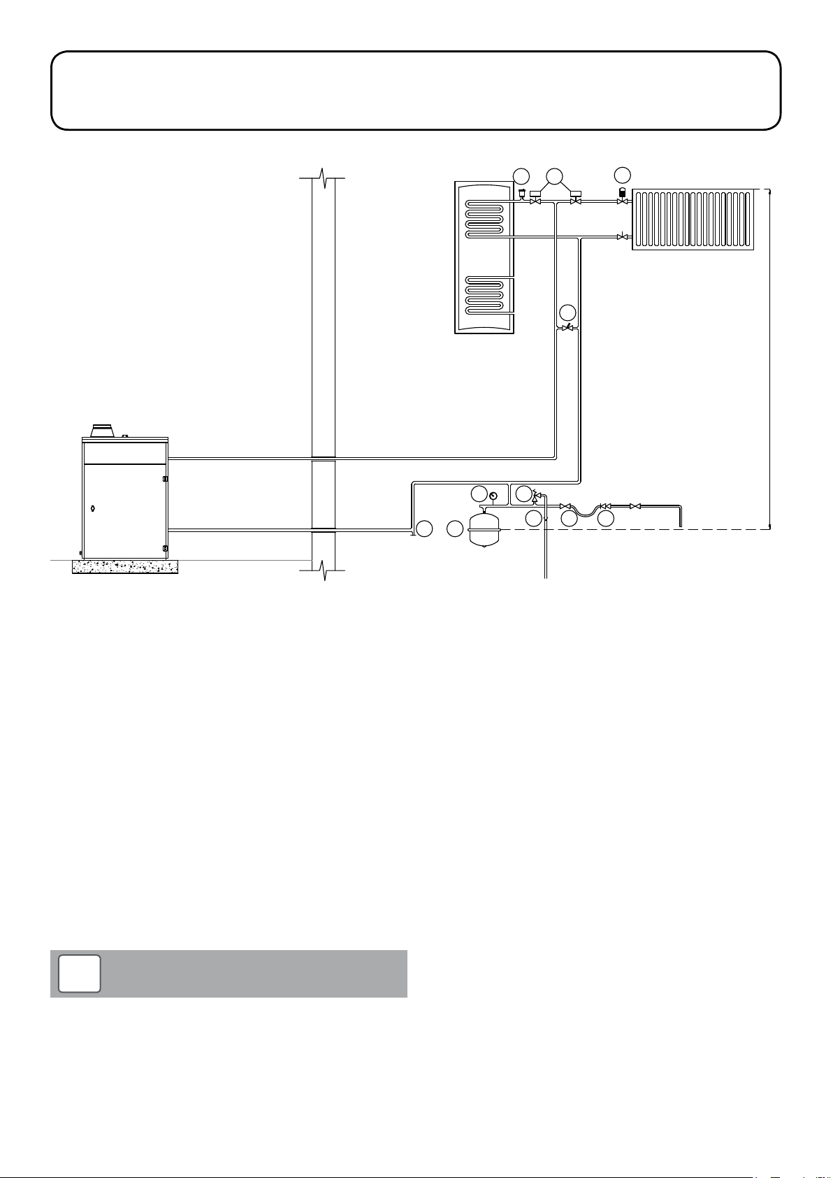
6.1 Sealed System Requirements
1. Expansion vessel
2. Pressure gauge
3. Pressure relief valve
4. Tundish
5. Removable filling loop
6. Double check valve
7. Automatic air vent
8. HW/HTG zone valves
9. Thermostatic radiator valve
10. Automatic bypass
11. Drain point
Figure 6-1: Sealed heating system components
All Grant Vecta boilers are suitable for use with sealed systems
complying with the requirements of BS EN 12828:2003, BS EN
12831:2003 ad BS EN 14336:2004.
The system must be provided with the following items:
• Diaphragm expansion vessel complying with BS EN 13831:2007
• Pressure gauge
• Pressure relief (safety) valve
• Approved method for filling the system
6.1.1 Expansion vessel
The expansion vessel can be fitted in either the return or flow pipework
in any of the recommended positions as shown in Figure 6-1. To
reduce the operating temperature of the expansion vessel, position it
below the pipe to which it is connected.
The expansion vessel may be positioned away from the system,
providing the connecting pipe is not less than 13 mm diameter. If the
expansion vessel is connected via a flexible hose, care must be taken
to ensure that the hose is not twisted.
!
Ensure that the expansion vessel used is of suf ficient size for
the system volume.
Refer to BS 7074:1:1989 or The Domestic Heating Design Guide
for sizing the required vessel.
NOTE
6.1.2 Pressure Gauge
The pressure gauge must have an operating range of 0 to 4 bar.
It must be located in an accessible place next to the filling loop for the
system.
6.1.3 Safety Valve
The safety valve (provided with the boiler) is set to operate at 2.5bar. It
should be fitted in the flow pipework near to the boiler.
The pipework between the safety valve and boiler must be
unrestricted, i.e. no valves. The safety valve should be connected to a
discharge pipe which will allow the discharge to be seen, but cannot
cause injury to persons or damage to property.
6.1.4 Filling Loop
Provision should be made to replace water lost from the system. This
can be done manually (where allowed by the local water undertaking)
using an approved filling loop arrangement incorporating a double
check valve assembly.
The filling loop must be isolated and disconnected af ter filling the
system.
6.1.5 Heating System
The maximum ‘setpoint’ temperature for the central heating water is
75°C. Refer to Section 1.1.
An automatic air vent should be fitted to the highest point of the
system.
If thermostatic radiator valves are fitted to all radiators, a system bypass must be fitted. The by-pass must be an automatic type.
All fittings used in the system must be able to withstand pressures
Section 6: Sealed SystemsPage 18
Page 19
up to 3 bar. Radiator valves must comply with the requirements of BS
2767:1991.
One or more drain taps (to BS 2879) must be used to allow the
system to be completely drained.
11. Close the fill point and double check valves either side of the
filling loop and disconnect the loop.
12. Check the system for water soundness, rectifying where
necessary.
6.2 Filling the Sealed System
Filling of the system must be carried out in a manner approved by the
local Water Undertaking.
!
Only ever fill or add water to the system when it is cold and the
boiler is off. Do not overfill.
The procedure for filling the sealed system is as follows:
1. Check the air charge pressure in the expansion vessel BEFORE
filling the system.
The expansion vessel charge pressure should always be slightly
greater than the maximum static head of the system, in bar, at
the level of the vessel (1 bar = 10.2 metres of water). Refer to
Figure 6-1.
The charge pressure must not be less than the actual static head
at the point of connection.
!
The air charge pressure may be checked using a tyre pressure
gauge on the expansion vessel Schraeder valve. The vessel
may be re-pressurised, when necessary, using a suitable
pump. When checking the air pressure, the water in the heating
system must be cold and the system pressure reduced to zero.
WARNING
NOTE
6.3 Venting the Pump
For those heating circulating pumps fitted with a vent plug, it is
important that the pump is properly vented to avoid an air lock and
also prevent it running dry and damaging the bearings.
Unscrew and remove the plug from the centre of the pump motor.
Using a suitable screwdriver, rotate the pump spindle about one turn.
Replace the plug in the motor. Do not over tighten.
!
Some heating circulating pumps are not fitted with a
vent plug so it is not possible to vent these pumps in the
manner described above. Refer to pump manufacturers own
instructions for further details.
NOTE
6.4 Pressure Relief (Safety) Valve Operation
Check the operation of the pressure relief (safety) valve as follows:
1. Turning the head of the valve anticlock wise until it clicks. The
click is the safety valve head lifting off its seat allowing water to
escape from the system.
2. Check that the water is escaping from the system.
3. Top-up the system pressure, as necessary.
Check that the small cap (or screw) on all automatic air vents is
open at least one turn. The cap (or screw) remains in this position
from now on.
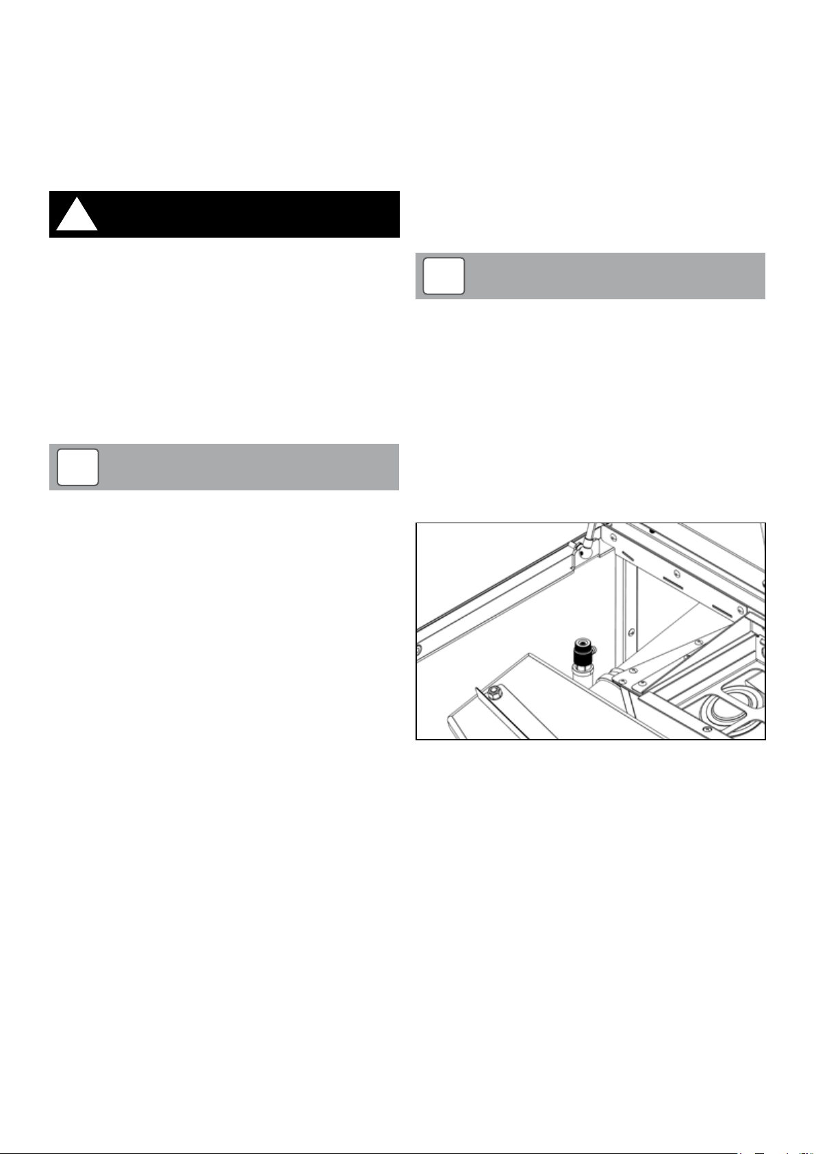
2. Open the hinged hopper lid. Undo the t wo screws (one on the
right and one on the left) and remove the access cover from the
top of the boiler.
Pull out the air vent tube so that it will discharge any water
outside the boiler and have a small container available to catch
this water. Open the manual air vent located under the access
cover. Refer to Figure 6-2.
3. Ensure that the flexible filling loop is connected and that the
double check shut off valve connecting it to the water supply is
closed. A valve is open when the operating lever is in line with the
valve, and closed when it is at right angles to it.
4. Open the fill point valve.
5. Gradually open the double check valve from the water supply
until water is heard to flow.
6. When the needle of the pressure gauge is between 0.5 and 1.0
bar, close the valve.
7. Vent each radiator in turn, starting with the lowest one in the
system, to remove air.
8. Continue to fill the system until the pressure gauge indicates
between 0.5 and 1.0 bar. Close the fill point valve. The system fill
pressure (cold) should be 0.2 - 0.3 bar greater than the vessel
charge pressure – giving typical system fill pressures of approx
0.5 bar for a bungalow and 1.0 bar for a two storey house.
Refer to the Domestic Heating Design Guide for further
information if required.
9. Repeat steps 7 and 8 as required until system is full of water at
the correct pressure and vented.
10. Water may be released from the system by manually operating
the safety valve until the system design pressure is obtained
Figure 6-2: Location of manual air vent (wash system removed for
clarity)
Section 6: Sealed Systems Page 19
Page 20
7 Flue System and Air Supply
7.1 Air Supply
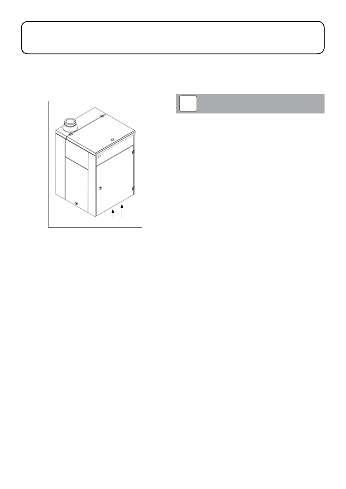
The Grant External Vecta wood pellet boiler draws air for combustion
from the surrounding atmosphere. The combustion air inlet to the
boiler is provided by the gap along the bottom edge of the hinged
front door. This opening must not be blocked off or obstructed in any
way. Refer to Figure 7-1.
Boiler air inlet
Figure 7-1: Boiler air inlet
7.2 Flue Terminal Position and Clearances
The Grant External Vecta wood pellet boilers have high operating
efficiencies and low flue gas temperatures. Only the Grant ‘Biomass’
insulated twin-wall flue system can be used with the Grant External
Vecta boiler.
!
The flue installation must be in accordance with the
requirements of The Building Regulations Approved Document
J – Section 2: Appliances burning solid fuel.
The following points MUST be taken into consideration with regard to
the design and installation of the flue system:
• The flue system must include the Inspection Pipe (product code:
WPBOM/IP) , which should be fitted directly to the flue outlet of
the boiler. This incorporates both a combustion test point and a
flue inspection hatch. Refer to Section 7.4.5.
• Grant recommends that the flue is vertical for a minimum
distance of 600mm (measured from the top of the boiler) before
any elbow. However, this is not essential for the operation of the
boiler.
• There must NOT be any change of direction greater than 45°
from the vertical, e.g. two 45° elbows must NOT be used
together to form a 90° elbow.
• The flue system must NOT include any horizontal sections of flue.
• Grant recommends that an adjustable flue extension be fitted in
the flue system as close to the boiler as possible, to enable the
flue system to be disconnected from the boiler flue connection,
as and when required, for future boiler maintenance.
• The weight of the flue system must NOT be carried by the
boiler, but must be supported using the various support options
available in the Grant ‘Biomass’ flue system. Refer to Section
7.4.4.
• The minimum distance between the outer surface of any part of
the flue system and any combustible material is 60mm. Refer to
Section 7.3 for flue system designation. A minimum clearance of
25mm around the flue is required for the fitting/removal of locking
bands.
• The flue terminal should be located in a downdraught free area,
i.e. above the roof, where it can discharge freely and not present
a fire hazard whatever the wind conditions. The flue outlet
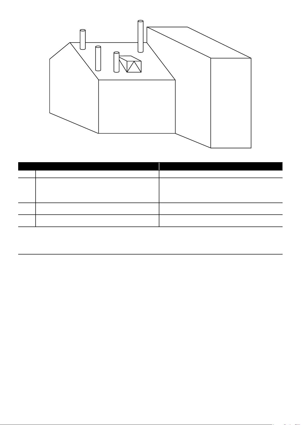
positions shown in Figure 7-2 (from Approved Document J) can
meet this requirement.
• The heights and separation distances shown in Figure 7-2 may
have to be increased in particular cases, e.g. where high wind
exposure, surrounding tall buildings, or adjacent trees can cause
adverse wind effects.
• No other appliance can be connected to the boiler flue.
• Any condensate in the flue can run back into the boiler. A
condensate drain at the base of the flue system is not required
as the flue system is designed to allow the condensate to run
back into the boiler.
NOTE
Section 7: Flue System and Air SupplyPage 20
Page 21
Adjacent
A
D
building
B
C
Regulated building
Figure 7-2: Flue terminal positions
Point where flue passes through weather surface (Notes 1, 2) Clearances to flue outlet
A At or within 600mm of the ridge At least 600mm above the ridge
At least 2300mm horizontally from the nearest point on the weather
surface and:
B Elsewhere on a roof (whether pitched or flat)
Below (on a pitched roof) or within 2300mm horizontally to an openable
C
rooflight, dormer window or other opening (Note 3)
Within 2300mm of an adjoining or adjacent building, whether or not
D
beyond the boundary (Note 3)
Notes
1. The weather surface is the building ex ternal surface, such as its roof, tiles or ex ternal walls.
2. A flat roof has a pitch less than 10°.
3. The clearance given for A or B, as appropriate, will also apply.
4. A ver tical flue fixed to an outside wall should be treated as equivalent to an inside flue emerging at the nearest edge of the roof.
a) at least 1000mm above the highest point of intersection of the chimney
and the weather surface; or
b) at least as high as the ridge.
At least 1000mm above the top of the opening.
At least 600mm above any part of the adjacent building within 2300mm.
The above clearances are as specified in Building Regulations Approved Document J. Also refer to Approved Document J of
either the England and Wales Building Regulations for further requirements on the installation of flue systems for solid fuel
appliances.
7.3 Flue System Specification
The Grant ‘Biomass’ 125mm (5in) flue system is a fully insulated stainless steel t win-wall flue finished with either a Black or White Polyester
Powder paint finish. This insulated flue system reduces the possibility of the condensate freezing in the flue, and also has a high corrosion
resistance suitable for solid fuel.
The CE designation of this flue system (to EN1856-1) is:
T450 N1 W V2 L50 050 G 60
Where:
• T450 (Temperature rating) - 450°C maximum temperature for continuous operation
• N1 (Pressure rating) - Negative pressure
• W (Condensate resistance) - Able to contain condensate within the flue
• V2 (Corrosion resistance) - Resistant to attack from products of combustion from natural wood
• L50 (Liner material) - 316L stainless steel
• 050 (Material thickness) - 0.5mm
• G (Soot fire resistance) - Tested at 1000°C for 30mins
• 60 (Distance to combustibles) - 60mm minimum clearance is required from combustibles
Masonry chimneys MUST be lined using the 125mm stainless steel flexible ‘smoothbore’ liner – available as part of the Grant ‘Biomass’ flue
system. Refer to Section 7.4.9.
Section 7: Flue System and Air Supply Page 21
Page 22
7.4 Flue System Assembly
Male collar
7.4.1 Boiler Flue Connection
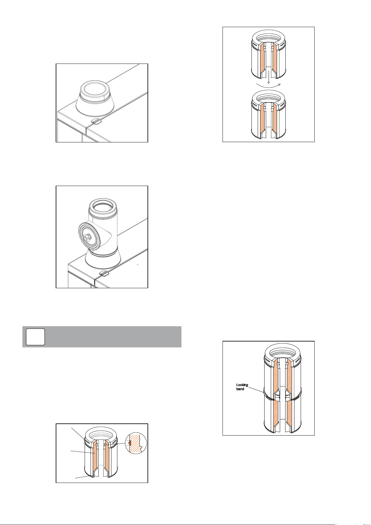
The Grant External Vecta boiler is supplied with a flue outlet located
on the top of the boiler in the rear left corner and is designed to fit the
Grant ‘Biomass’ flue system. Refer to Figure 7-3.
Figure 7-3: Boiler flue connection
The flue system must include the Grant Inspection Pipe (Grant Ref.
WPBOM/IP), which should be fitted to the outlet of the boiler. This
incorporates both a combustion test point and a flue inspection hatch.
Refer to Figure 7-4 and also Section 7.4.5.
Figure 7-4: Inspection pipe
When fitting the flue to the boiler flue outlet, the lip seal supplied with
the flue component must be fitted into the groove around the inside
surface of the flue, and the locking band fitted to secure the joint.
!
NOTE
Figure 7-6: Twist lock joint between components
To join two components together:
All flue joints must have a lip seal gasket fitted. This seal is supplied
with the flue component.
To temporarily assemble the flue system components, to check
component lengths, alignment of connections, etc. DO NOT fit the lip
seals. However, for FINAL assembly the lip seals provided MUST be
fitted at EVERY joint.
First fit the lip seal supplied into the groove (in the inner flue liner) at
the ‘male collar’ end of the flue component. Refer to Figure 7-5. The
lip seal should be fitted ‘dry’, i.e. with no lubricating grease applied at
this stage. The lubricating grease (also supplied with the component)
should be applied to the seal after it is fitted but before fitting the two
flue components together.
Loosen the locking band at the ‘female collar’ end. Insert the ‘male
collar’ into the ‘female collar’ and twist through 1/6 of a turn to lock in
place. Refer to Figure 7-6.
Ensure that the two beaded ends of the flue components are in
contact with each other all round. Position the locking band and so
that it grips the beaded edge of both components and fasten using
the spring clip. The locking bands provided MUST be fitted at ALL flue
joints. Refer to Figure 7-7.
To allow for alignment, the female collars of the elbows do NOT have
the twist lock flutes, but the locking band MUST still be used to secure
the two flue components together.
The Inspection Pipe should be positioned such that the cover
plate faces to the left, not towards the right or front of the
boiler.
7.4.2 Joining Components
All the ‘Biomass’ system twin-wall flue components (with the
exception of the elbows) use a ‘twist lock’ jointing system. The ‘male
collar’ end of the flue component MUST always be uppermost when
fitted.
Insulation
Female collar
Figure 7-5: Male and female flue connections
Viton gasket
seal detail
Locking
band
Figure 7-7: Fitting of locking band
Section 7: Flue System and Air SupplyPage 22
Page 23

7.4.5 Flue Inspection Pipe (product code: WPBOM/IP)
!
All joints in the flue system must be accessible for inspection.
No joints should be located within a wall, floor or ceiling spaces
or any other inaccessible place.
7.4.3 Adjustable Length
The Grant ‘Biomass’ flue system includes an Adjustable flue
extension. Refer to Section 7.9. This allows any of the straight flue
extension components to be extended in length by between 00mm to
230mm (this does not apply to the 200mm extension). This adjustable
extension must be used in conjunction with any straight extension
(1000mm, 500mm, 333mm or 200mm) to achieve the actual straight
length required.
To fit the adjustable ex tension, first remove insulation from between
the inner and outer walls of the component, as necessary. Fit the
open end over the ‘male collar’ end of the fixed extension and adjust
to achieve the required overall length. Secure the two components
together using the wide locking band supplied.
!
The adjustable section is NOT loadbearing, therefore adequate
support of the flue system MUST be provided immediately
above the adjustable extension.
7.4.4 Support Components
The weight of the flue system is considerable. It must NOT be carried
by the flue connection on the appliance, but requires independent
support using one or more of the various flue support options
available in the Grant ‘Biomass’ flue system.
Intermediate Top Plate (product code: WPB/TP)
Flue systems running up against an external wall surface can be
supported using the Intermediate Top Plate. This is mounted on either
a pair of Wall Support Side Plates (product code: WPB/WS or WPB/
WS) or a pair of Cantilever brackets (product code: WPB/CANT),
which are fastened to the wall, to provide support at either the base,
or part way up a vertical section of flue.
The ‘female collar’ (on the underside of the plate) is fitted into the flue
below and the ‘male collar’ (on the upper side of the plate) is a twistlock connection into the flue above. Both joints are secured using the
clamp bands provided.
Wall Brackets (product codes: WPB/WB60 and WPB/WB300)
Both the Wall bracket and the Adjustable Wall Bracket (Grant Ref.
WPB/WB60 and WPB/WB300) are NOT load-bearing but are designed
to give lateral support only. Wall brackets should be fitted with a
maximum spacing of 3m on straight runs of flue and at any offset to
ensure the system is rigidly supported.
WARNING
NOTE
!
Failure to maintain a clean flue can result in the emission of
flue gases into the dwelling or damage from fire in the flue.
Refer to Section 11.4.
The Building Regulations Approved Document J requires a flue
system to have the means to be inspected and cleaned as required.
To meet this requirement, a Flue Inspection Pipe incorporating an
inspection hatch and combustion test point is available as part of the
Grant ‘Biomass’ flue system. This must be fitted directly to the boiler
flue connector with the inspection hatch facing to the LEFT.
7.4.6 Elbows
Two elbows are available - 30° (product code: WPB/30) and 45°
(product code: WPB/45). To allow for alignment, the female collars of
these elbows do NOT have the twist lock flutes, but the locking band
MUST still be used to secure the two flue components together.
There should be no more than 2 elbows – of maximum angle 45°
from the vertical – fitted between the inspection hatch of the flue
Inspection pipe (at the boiler) and the terminal. This can be increased
to a maximum of four elbows (maximum 45°) bet ween the boiler and
terminal if there is a second flue Inspection Pipe fitted between the
second and third elbows. Any Inspection hatch must be accessible for
checking and cleaning purposes.
Roof Cowl (product code: WPB/RC)
The Rain Cap type terminal is fitted either directly to the Intermediate
Top Plate on the top of the flue or, if necessar y (i.e. to achieve the
required distance between the terminal and the roof surface), to a
length of flue that is, in turn, connected to the Intermediate Top Plate.
Fit the Terminal to either the Intermediate Top Plate or flue extension
and twist through 1/6 of a turn to lock in place. Ensure that the
locking band (supplied with the terminal) is correctly fitted to secure
the terminal in place. Refer to Section 7.4.2 for further details on
connecting the flue components.
WARNING
7.5 Flue Testing
Once installed, the flue system should be tested in accordance with
the requirements of The Building Regulations Approved Document J,
Appendix E, Section E13 – Smoke Test I.
7.6 Flue Notice Plate
The Building Regulations Approved Document J requires a notice
plate that conveys essential information regarding the flue installed
to be permanently displayed. A suitable self-adhesive notice plate
is supplied with the Grant ‘Biomass’ flue system and this must be
completed by the installer and displayed in an unobtrusive but
obvious position within the building concerned, e.g. on the inside of
the boiler door.
Structural Locking Band (product code: WPB/LBEX T)
A height of up to 3m above the last support at the roof can be
achieved, without the need for guy wires, by using an ex tended
Structural locking band at the joint immediately below, and at every
joint above, the last flue support.
Section 7: Flue System and Air Supply Page 23
Page 24
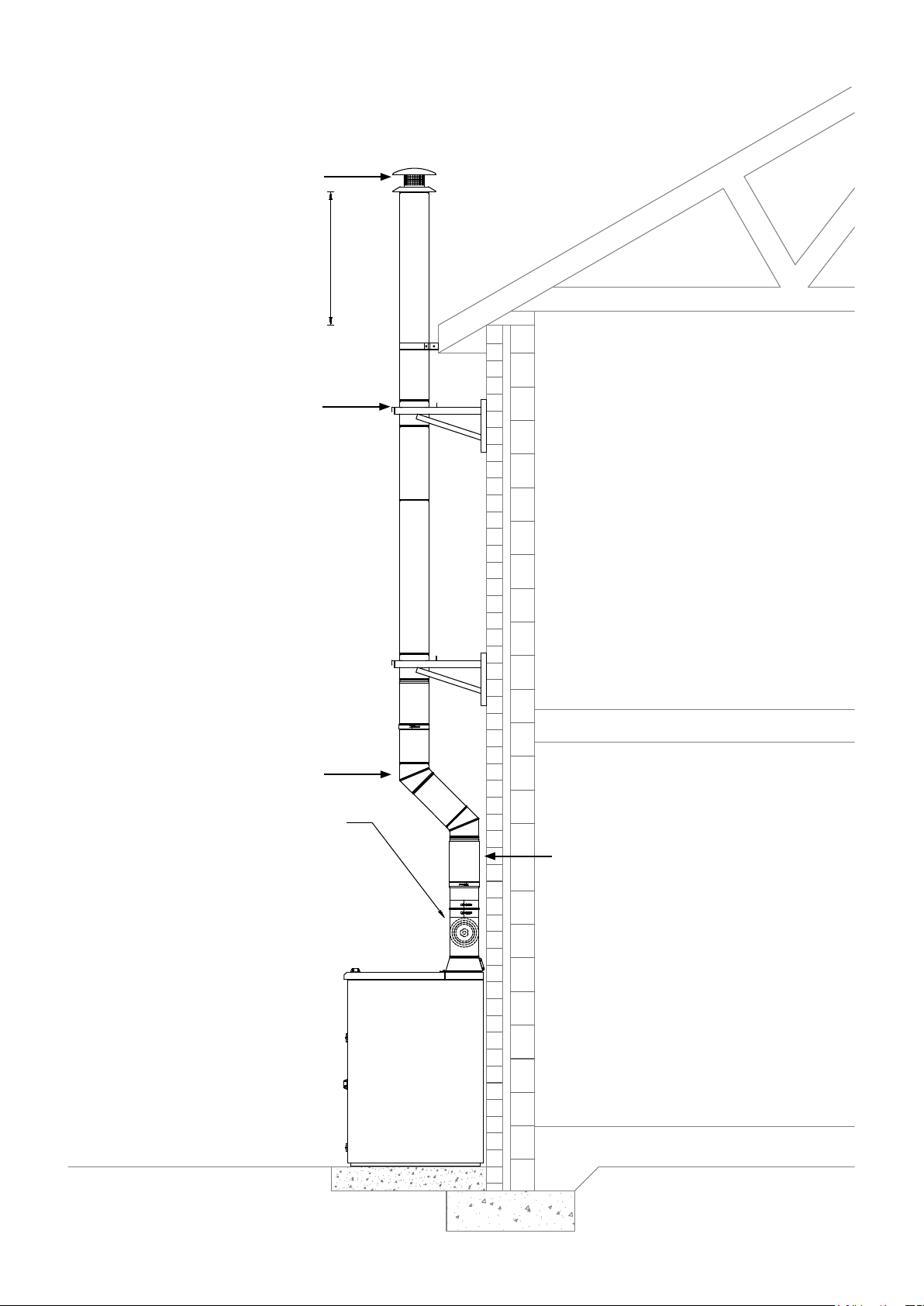
7.7 Typical Flue Systems
Rain cap
600
Minimum
Cantilever
45° bend
Inspection pipe facing left
(when viewed from front of
boiler) for ease of access.
Adjustable extension
Section 7: Flue System and Air SupplyPage 24
Page 25
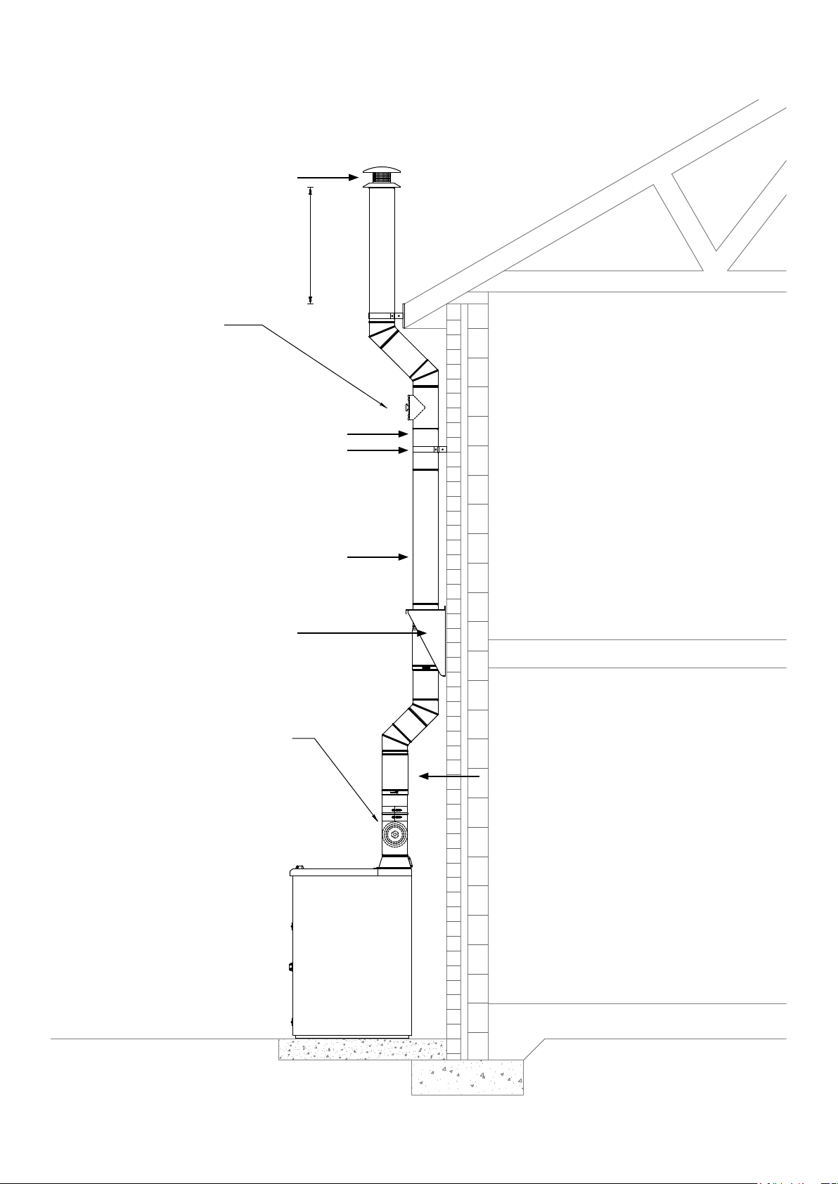
Minimum
Additional access
before second offset
Rain cap
600
Adjustable extension
Wall bracket
Extension
Wall support side plate
Inspection pipe facing left
(when viewed from front of
boiler) for ease of access.
Adjustable extension
Section 7: Flue System and Air Supply Page 25
Page 26
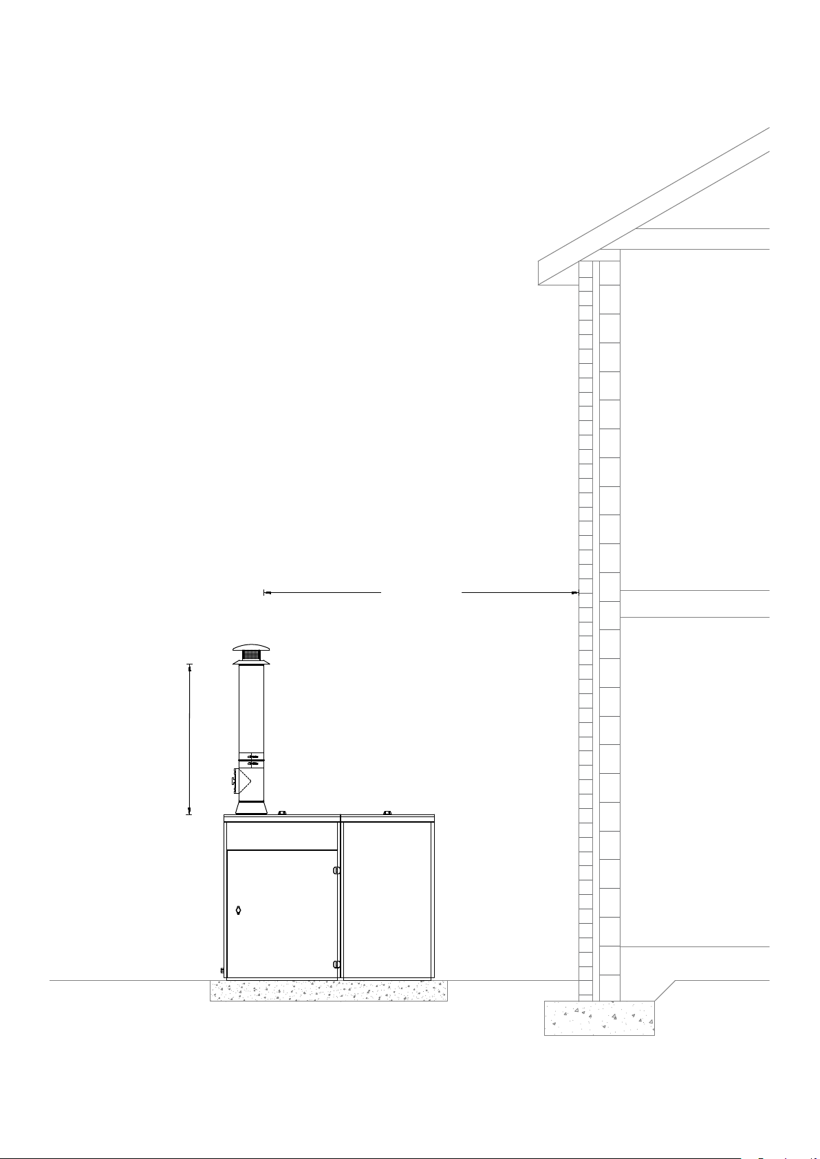
1400
Minimum
2300
Minimum
Section 7: Flue System and Air SupplyPage 26
Page 27
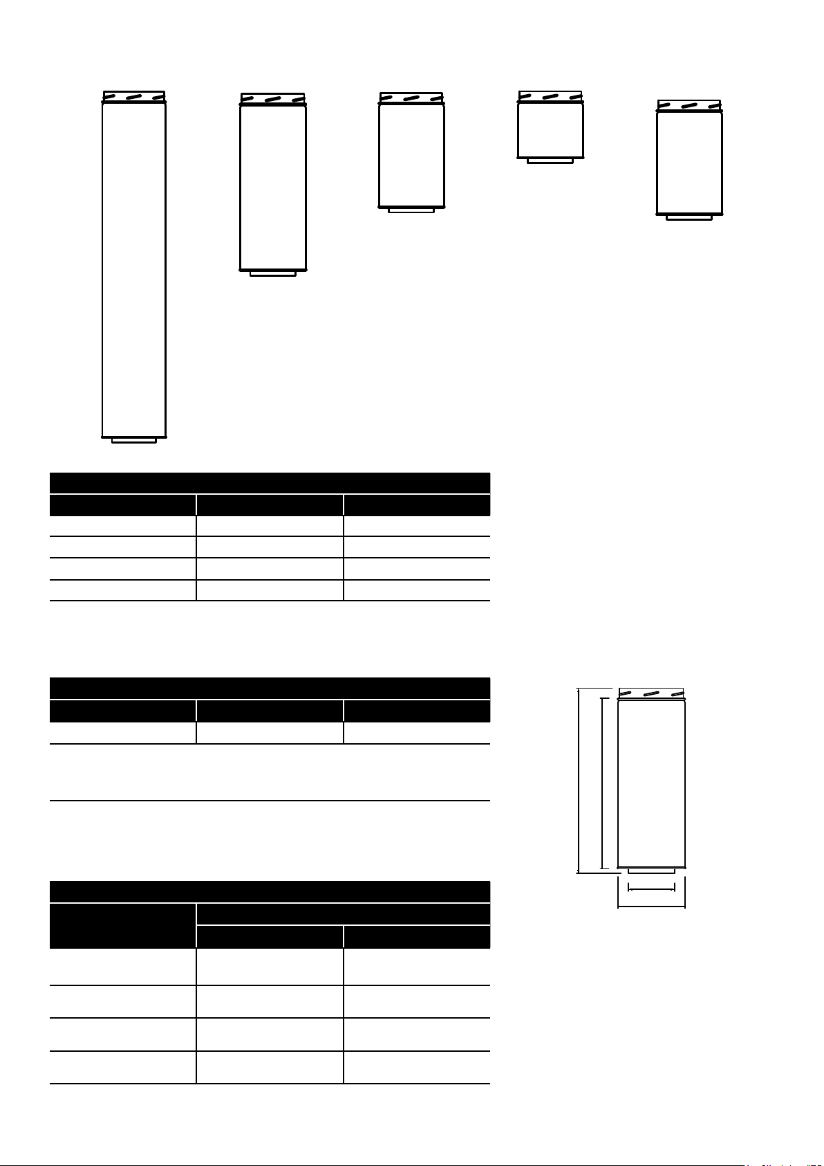
7.8 Flue System Component Dimensions
Ø125
Ø180
Ø125
Ø180
Nominal length
200mm
333mm
500mm
1000mm
Straight pipe lengths (mm)
Product code Nominal length Ef fective length
WPB/EXT200 200 160
WPB/EXT333 333 293
WPB/EXT500 500 460
WPB/EXT1000 1000 960
Adjustable
75 - 250mm
Complete with locking band.
Telescopes over pipe below.
Minimum engagement should be half the diameter.
This component is NOT load-bearing.
WPB/ADJ250 and
WPB/ADJ250 and
WPB/ADJ250 and
WPB/ADJ250 and
Adjustable pipe length (mm)
Product code Nominal length Ef fective length
WPB/ADJ250 75- 250 mm 50 - 230mm
Straight and adjustable pipe lengths (mm)
Product code
WPB/EXT200
WPB/EXT333
WPB/EXT500
WPB/EXT1000
Minimum Ma ximum
350 440
393 573
560 740
1060 1240
Effective length
Effective length
Ø125
Ø180
Section 7: Flue System and Air Supply Page 27
Page 28
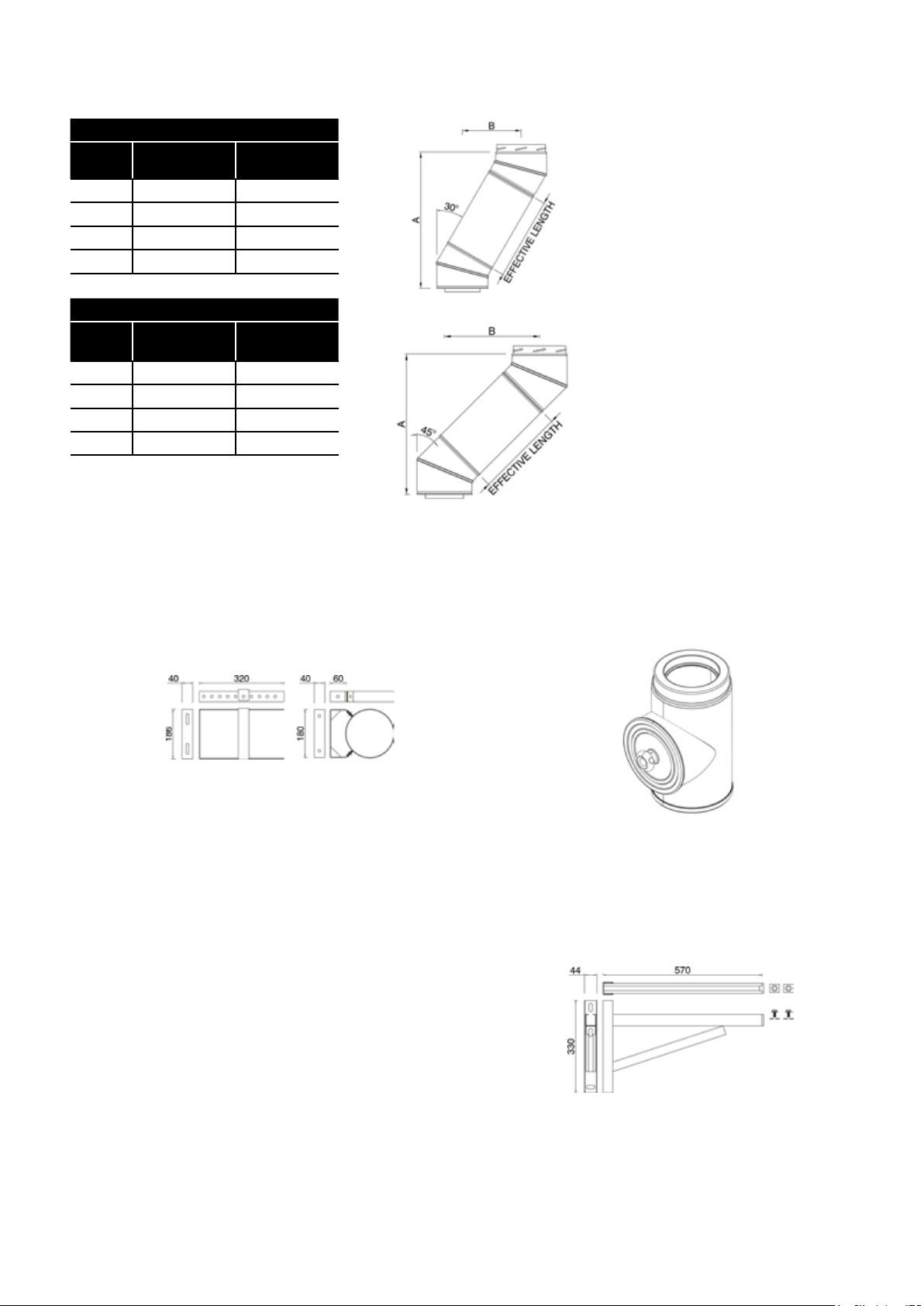
Double 30° bend and straight pipe length (mm)
Effective
length
960 A / B 1061 / 542
460 A / B 628 / 292
293 A / B 483 / 208
160 A / B 368 / 142
Double 45° bend and straight pipe length (mm)
Effective
length
960 A / B 933 / 784
460 A / B 580 / 431
293 A / B 462 / 313
160 A / B 367 / 218
Dimension Length
Dimension Length
7.9 Flue System Components
WPB/WB300 - Wall bracket (50 - 300mm)
WPBOM/IP - Inspection pipe
WPB/WB60 - Wall bracket (60mm)
WPB/CANT - Cantilever (570mm)
Section 7: Flue System and Air SupplyPage 28
Page 29
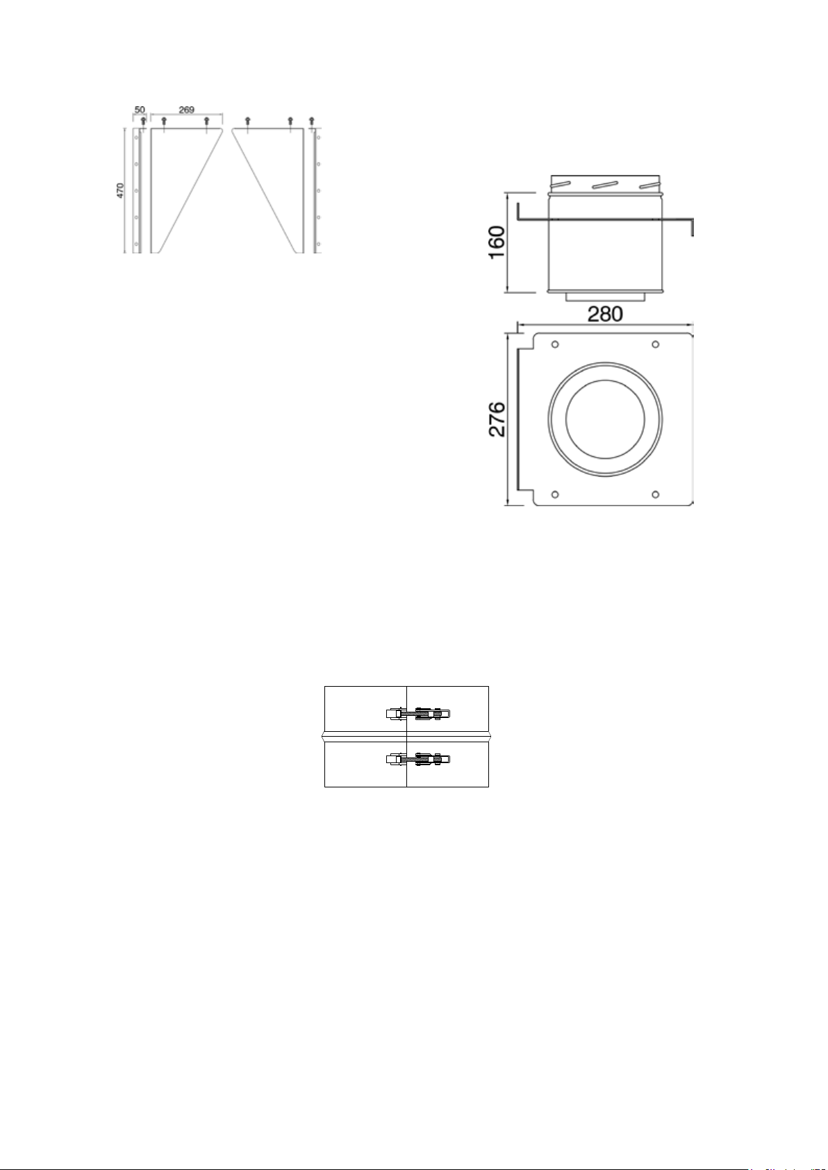
WPB/WS - Wall support side plate
WPB/RC - Rain cap
WPB/TP - Intermediate top plate
WPB/LBEXT - Structural locking band
Section 7: Flue System and Air Supply Page 29
Page 30
8 Electrical
8.1 General Requirements
The Grant External Vecta wood pellet boiler requires a ~230V 1ph 50
Hz electrical supply. The unit must be connected to a mains power
supply that is protected by a 5A fuse.
!
As a stationary appliance not fitted with a means for
disconnection from the supply mains having a contact
separation in all poles that provide full disconnection under
overvoltage category III, means for disconnection must be
incorporated in the fixed wiring in accordance with the wiring
rules.
A fused double pole switch, with contact separation of at least 3mm
in both poles, should be used for connection to the mains electrical
supply, serving the boiler and heating system controls only.
For the UK, the electrical installation must be carried out by a
competent installer in accordance with the requirements of the
Electricity at Work Regulations 1989 and BS7671:2008 – IET Wiring
Regulations 17th Edition (including all amendments).
All the wiring and supplementary earth bonding external to the boiler
must be in accordance with the above mentioned wiring regulations.
Any heating system controls, e.g. room thermostat, frost thermostat,
etc. connected to this boiler must be suitable for use on mains
voltage.
The boiler requires a permanent mains supply and switched live (for
the heating and hot water control) to operate the boiler. For details of
heating and hot water system controls refer to Sections 8.5 and 8.6.
Do NOT interrupt the permanent supply to the hopper/boiler with any
external controls.
WARNING
8.2 Boiler Electrical Connections
All the electrical connections (permanent mains supply and switched
live from the heating control system) to the boiler are made via the
terminal block in the lower left corner of boiler. Refer to Figures 8-7
and 8-10.
To access the terminal block, the terminal block cover must be
removed using the following procedure:
1. Open the front door of the boiler. First unlock and remove the
padlock (if fitted), rotate the knob of the catch clockwise to
unlatch and fully open the door.
2. Switch the electrical isolator to OFF. Refer to Figure 11-4.
3. Fit the multi-purpose tool (provided with the boiler) into the slot in
the door catch. Refer to Figure 11-5.
4. Lift the tool handle to release the door catch and fully open the
combustion chamber door of the boiler. Refer to Figure 11-6.
5. Undo the seven screws and remove the grey left hand cover
panel from the boiler
6. Remove the side access panel from the left side of the boiler.
Unlock/remove padlock (if fitted). Rotate the knob of the catch
clockwise to unlatch and remove the access panel
Figure 8-1: Boiler terminal block location (cover removed)
7. Slacken and remove the four screws securing the PCB housing.
Refer to Figure 8-2.
Figure 8-2: PCB housing screws
8. Carefully swing the PCB housing out from the side of the boiler
casing. Refer to Figure 8-3.
Figure 8-3: PCB housing pivoted
9. It will be necessary at this point to remove the photocell from
the mount on the left side of the boiler heat exchanger. Refer to
Figure 8-4.
Figure 8-4: Removing the photocell
Section 8: ElectricalPage 30
Page 31
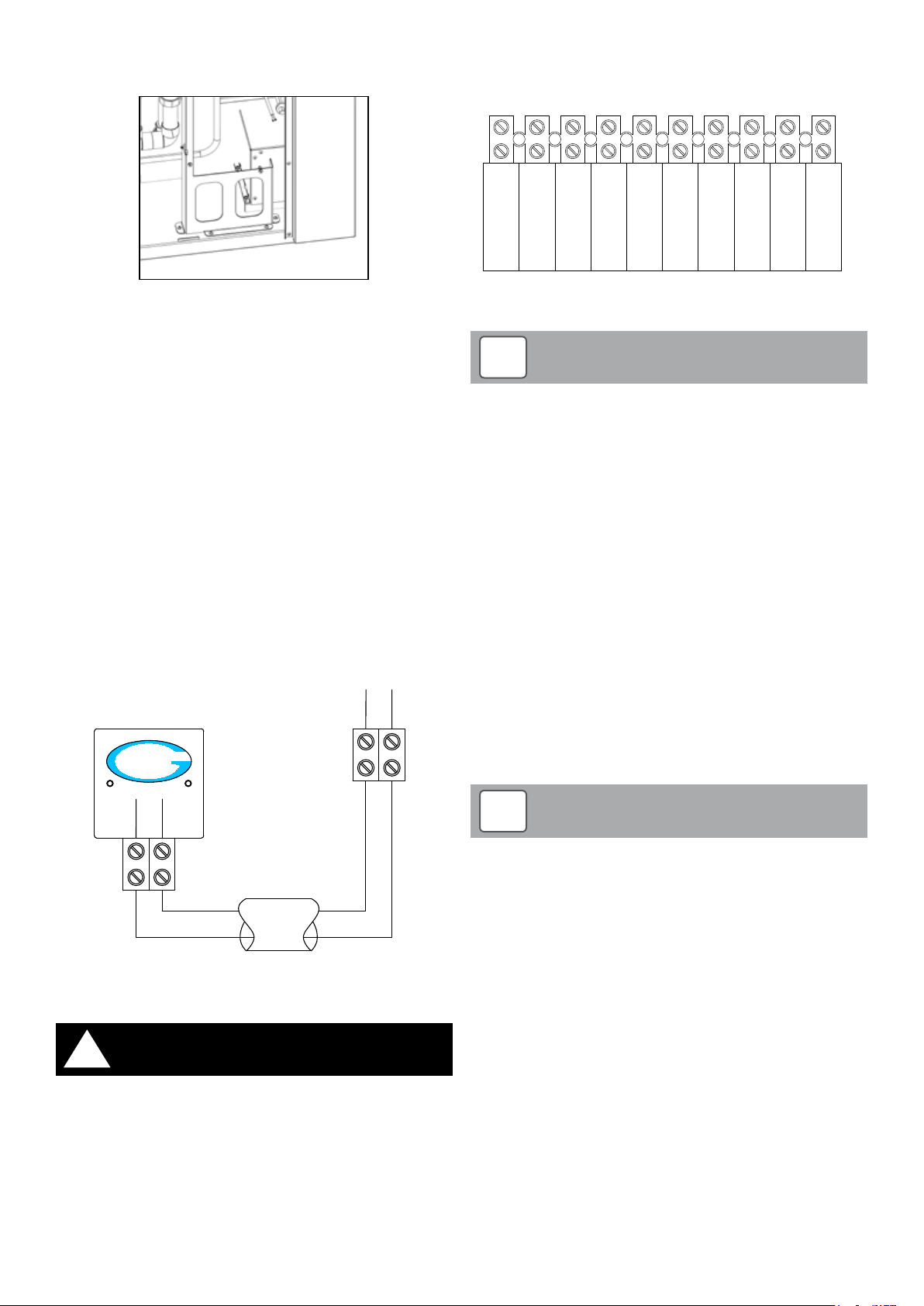
10. Locate the two terminal block cover fixing screws. Refer to Figure
2
3
LIVE
1
8-5.
Connect the mains supply to the boiler terminal block from left to
right, as per Figure 8-7.
Figure 8-5: Terminal block cover fixing screws
11. Unscrew both screws and remove the cover from the boiler.
12. After making the electrical connections the terminal block cover
must be re-fitted using the reverse of this procedure.
8.3 Remote Grant Logo Indicator Connections
The Grant logo indicator, supplied with the boiler, should be mounted
on a standard electrical back box (either recessed or surface
mounted) in a convenient and visible position within the house.
Using a suitable length of 0.75mm² 2-core PVC flex, connect the
remote Logo indicator to the corresponding terminal block in the
boiler. This terminal block is located to the lef t of the main boiler
terminal block, at the front lower left corner of the boiler (behind the
inner access cover). Refer to Figure 8-6 for electrical connection
details.
When connecting the Remote Grant Logo Indicator, ensure that the
terminal with the red wire on the boiler terminal block is connected to
the terminal with the red wire on the logo indicator terminal block.
Likewise, ensure that the terminals with the black wire on both the
boiler and logo indicator terminal blocks are connected together.
Black
Red
GRANT
VECTA
SWITCHED
LIVE
PERMANENT
LIVE
NEUTRAL
Figure 8-7: Boiler terminal block
!
If the 4-core flex bet ween the heating controls aand the boiler
terminal block is damaged at anytime, it must be replaced by
a comptent engineer in accordance with the requirements of
the Electricity at Work Regulations 1989 and BS7671:2008 – IET
Wiring Regulations 17th Edition (including all amendments).
NOTE
EARTH
SIDE STORE
SIDE STORE
NEUTRAL
EARTH
SIDE STORE
8.5 Heating System Controls
The boiler can be used in conjunction with typical heating control
system, e.g. ‘S-Plan’ or ‘Y-Plan’ type controls. Refer to Figures 8-9 and
8-10 for typical control system wiring diagrams.
8.6 Frost Protection
The Grant External Vecta wood pellet boiler is supplied with a factoryfitted frost protection thermostat. This is pre-set to operate when the
air temperature falls to 2°C.
This frost thermostat is located inside the PCB enclosure and is
connected between the Terminal 2 and Terminal 3 on the boiler
terminal block.
For details of the frost thermostat electrical connections refer to
Figures 8-8 and 8-9.
Red
Black
Figure 8-6: Connection diagram for Remote Grant Logo Indicator
8.4 Connecting the Power Supply
!
Before making any connections to the heating systems controls
ensure that the electrical supply is isolated at the fused spur
serving the controls and boiler, that the fuse has been removed
and the isolator is locked off.
Use a suitable length of 4-core flex, at least 1.5mm2 PVC between the
heating controls wiring centre or junction box and the terminal block in
the boiler. Ensure that the flex passes through and is secured by the
cable clamp next to the terminal block.
WARNING
!
In order for the frost protection thermostat to operate, ensure
that a link is fitted between terminal 1 and the permanent live
terminal on the boiler terminal block.
Grant recommends the use of a pipe thermostat (not supplied) in
conjunction with the frost thermostat to avoid unnecessary and
wasteful overheating of the property. This pipe thermostat should be
located on the boiler return pipe and set to operate at 25°C.
To connect a pipe thermostat:
• Remove the factory fitted link between terminals 1 and 2 on the
boiler terminal block.
• Connect the pipe thermostat between terminals 1 and 2 on the
boiler terminal block.
Refer to the Figures 8-8 and 8-9 for details of the frost thermostat and
pipe thermostat electrical connections.
For total system protection against freezing, particularly during
extended periods without electrical power, Grant recommends the
use of a combined heating system antifreeze and corrosion inhibitor,
used in accordance with the manufacturer’s instructions.
NOTE
Section 8: Electrical Page 31
Page 32
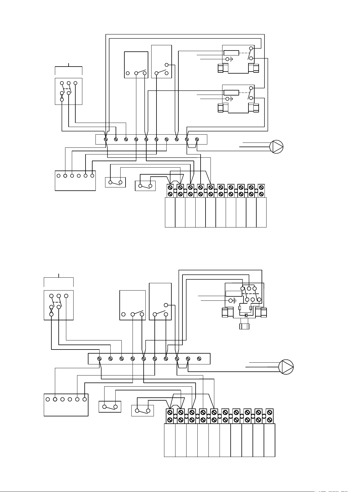
8.7 S-plan type system connection diagram
2-Port Zone Valve
Motor
Room
Stat
2 1 3
N
Grant 2-Channel
Wall Mounted
Programmer ESKIT
240V
50HZ
L N E
5A
2-Port Zone Valve
Motor
1 2 3 4 5 6 7 8 9 10
HTG
HW
L 1 2
3 4
Wiring
Centre
Grey
Grey
Orange
Orange
Brown
Blue
Green/Yellow
Green/Yellow
Brown
Blue
Brown
Blue
Green/Yellow
OFF OFF ON ON
HW HT HW HT
Cylinder
Stat
1
C
2
Blue
Green/Yellow
Brown
Pump
E
N
L
Vecta terminal block
Pipe Stat
(if fitted)
2
3
SWITCHED
LIVE
PERMANENT
LIVE
NEUTRAL
EARTH
SIDE STORE
NEUTRAL
SIDE STORE
EARTH
SIDE STORE
LIVE
1
Link
Frost Stat
(factory
fitted)
Link
Link*
Figure 8-8: Heating system controls - S-plan type system connection diagram
8.8 Y-plan type system connection diagram
Figure 8-9: Heating system controls - Y-plan type system connection diagram
240V
50HZ
L N E
5A
Blue
Brown
N
L 1 2 3 4
OFF OFF ON ON
HW HT HW HT
Grant 2-Channel
Wall Mounted
Programmer ESKIT
Green/Yellow
Orange
Grey
White
Cylinder
Stat
1
C
2
Room
Stat
2 1 3
1 2 3 4 5 6 7 8 9 10
Link
Frost Stat
(factory
fitted)
Pipe Stat
(if fitted)
Link*
1
Link
3
2
Vecta terminal block
Blue
Green/Yellow
SWITCHED
LIVE
Motor
13k2W270k
0.25W
3-Port Mid Position
Zone Valve
Wiring
Centre
Brown
PERMANENT
LIVE
NEUTRAL
EARTH
Green/Yellow
Blue
SIDE STORE
SIDE STORE
NEUTRAL
* If a pipe stat is
fitted, please remove
the factory fitted link
between terminals 1
and 2
E
N
L
* If a pipe stat
is fitted, please
remove the factor y
fitted link between
SIDE STORE
EARTH
LIVE
terminals 1 and 2
Pump
Section 8: ElectricalPage 32
Page 33

8.9 Boiler Wiring Diagram
NOTE
!
Earth and some Neutral connections
have been excluded for clarit y.
All switches are shown in the closed
position.
Figure 8-10: Boiler wiring diagram
Section 8: Electrical Page 33
Page 34
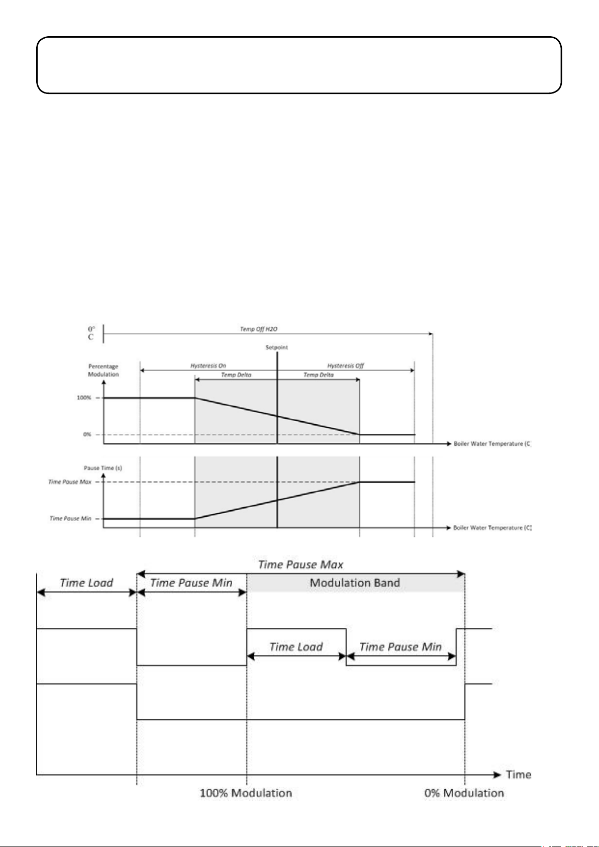
9 Boiler Operation
9.1 General
The control system automatically regulates all aspects of the boiler
operation including:
• Burner start up and shut sequences
• Output modulation
• Combustion
It also controls the automatic cleaning sequences for both the burner
and heat exchanger(s) and indicates when a service is required. The
automatic cleaning of the burner brazier and heat exchanger(s) is
activated after the pellet feed auger running time has exceeded the
period pre-set in the burner control settings. Refer to Section 9.3.
The boiler control panel (located on the front panel of the boiler)
features a display screen and six control buttons. These buttons are
used to access and adjust the boiler control parameters. Refer to
Section 9.4.
The control system also has a diagnostic feature, where a fault code
will be displayed on the control panel LCD. Refer to Section 12 – Fault
Finding.
9.2 Modulation
Adjustable boiler control parameter numbers are shown in square
brackets. Refer to Parameter Menu in Section 9.7.
The boiler has a ‘setpoint’ temperature. This is the target flow
temperature from the boiler. The default ‘setpoint’ temperature is
75°C, but this can be adjusted by the installer if required. The boiler
temperature is monitored by a thermistor located in the water jacket
of the boiler and this is used by the control system to control the
modulation of the boiler output.
When a demand from the heating system controls is detected and the
ON/STANDBY switch is set to ON, the circulating pump runs and the
boiler control checks that the boiler water temperature is cool enough
for the boiler/burner to start. The boiler water temperature must be at
least the ‘Hysteresis On’ temperature value below the ‘Set Point’ (i.e.
boiler temperature < ‘Set Point’ – ‘Hysteresis On’).
If not, the circulating pump continues to run and the boiler water
temperature checked until the conditions to start the boiler/burner are
met.
Figure 9-1: Boiler modulation
Figure 9-2: Pellet auger modulation
Section 9: Boiler OperationPage 34
Page 35

The boiler water temperature is continually monitored during boiler
operation. If it exceeds ‘Hysteresis On’ temperature plus ‘Set Point’
temperature (i.e. boiler temperature > ‘Set Point’ + ‘Hysteresis On’),
OR the ‘Temp Off H2O’ value, the boiler/burner will stop operating.
The boiler water temperature will now have to drop to below the ‘Set
Point’ – ‘Hysteresis On’ temperature before the boiler/burner will
operate again.
There is a pre-set ‘Temp Delta’ value (5°C). This gives the temperature
band above and below the ‘Set Point’ temperature – within which the
boiler output will be modulated. Refer to Figure 9-1.
When the boiler temperature is below the ‘Set Point’ temperature
minus ‘Temp Delta’ value, the modulation of the burner is set to
maximum.
When the boiler temperature is above the ‘Set Point’ temperature plus
‘Temp Delta’ value, the modulation of the burner is set to minimum.
When the boiler temperature is within the modulation band,
the modulation level is varied in direct proportion to the boiler
temperature, i.e. boiler output varies linearly from maximum at the
bottom of the modulation band (boiler temperature = ‘Set Point’ –
‘Temp Delta’) to minimum at the top of the modulation band (boiler
temperature = ‘Set Point’ + ‘Temp Delta’). Refer to Figure 9-1.
Pellets are delivered to the burner by switching the pellet feed auger
on and off. The auger ‘On’ period is defined by the pre-set ‘Time
Load’ parameter (1.7s).
The burner is modulated by varying the ‘pause’ time between the preset parameters ‘Pause Max Power’ [7] at ma ximum output and ‘Pause
Min Power’ [6] at minimum output. Refer to Figure 9-2.
The fan speed is automatically controlled to maintain the required air
supply for the output of the boiler as the burner modulates, i.e. if the
output decreases the air supply (and fan speed) will be automatically
reduced, if the output increases the air supply (and fan speed) will be
automatically increased.
This control of the air supply is achieved using the Lambda sensor,
located at the top of the primary heat exchanger. This measures
the oxygen level in the combustion gases and, via the boiler control
system, automatically adjusts the fan speed to achieve the required
level of oxygen for the output level of the burner at that time. Thus, as
the output changes so will the fan speed and air supply rate.
As this system is monitoring the oxygen level and adjusting the
air supply rate accordingly it will automatically compensate for the
gradual increase of ash blockage in the boiler over time, ensuring
that the combustion remains at the optimum throughout the period
between boiler services.
9.3 Automatic Cleaning
Adjustable boiler control parameter numbers are shown in square
brackets. Refer to Parameter Menu in Section 9.7.
The control system is programmed to carry out a self-cleaning
function on the burner brazier, heat exchanger and secondary
(condensing) heat exchanger at pre-set intervals.
This self-cleaning operation is automatically performed:
• on power-up, i.e. when the power to the boiler is connected (this
includes the cleaning of the condensing heat exchanger)
• after the pellet feed auger running time exceeds the pre-set
‘Clean Boiler’ parameter (480 mins).
The control system will inform the user when a service is required by
displaying a ‘Service’ message on the boiler control panel LCD when
the auger run time exceeds the pre-set ‘Hours ser vice’ period [14].
Once the service is completed, the service engineer can reset the
auger run time hours to zero so that the control will indicate when the
next service is required (after the ‘Hours Service’ value is exceeded).
Refer to Section 12 – Servicing.
If a fault occurs with the operation of the boiler, the control panel LCD
will display a fault code to assist in the diagnosis and rectification.
Refer to Section 13 – Fault Finding.
Section 9: Boiler Operation Page 35
Page 36
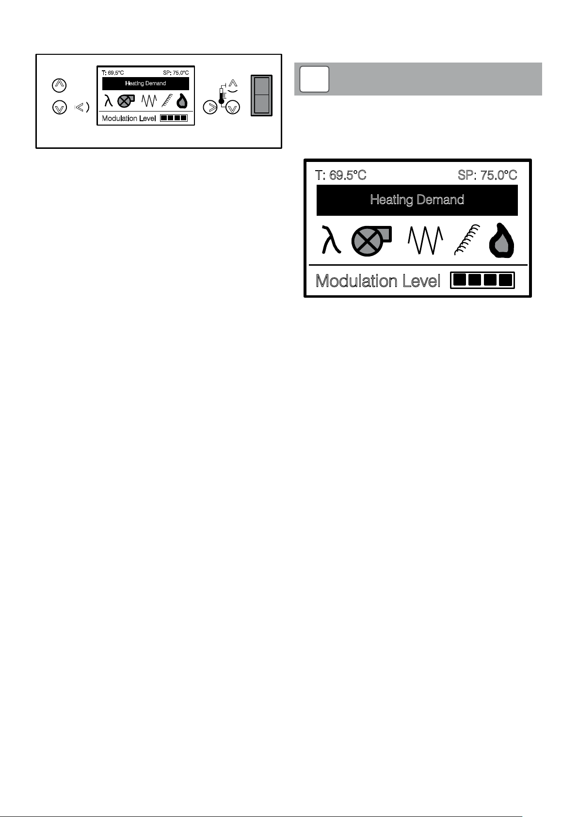
9.4 Boiler Control Panel
T: 69.5°C
SP: 75.0°C
Modulation Level
Heating Demand
STANDBY
ON
V
V
V
V
V
V
2
1
3
5
4
6
i
T: 69.5°C
SP: 75.0°C
Heating Demand
• Parameter Menu – to check/adjust the boiler control parameters
(Refer to Section 9.7) – this is accessed from the Service Menu.
Figure 9-3: Boiler control panel
The boiler control panel is located at the top front of the boiler (behind
the control panel cover) and includes the following:
• LCD screen: this displays the boiler operating condition and
(when necessary) a ‘Service’, ‘Fault’ or ‘Fuel Low Warning’
message for the user.
• Boiler control setting buttons: for boiler control system operation
and setting
• ‘ON/STANDBY’ switch: to switch the burner off when required,
by interrupting the switched live supply to the burner. This switch
does NOT isolate the electrical supply to the burner.
9.4.1 Function of buttons
The six control buttons perform different tasks depending on which
mode the control is in, as follows:
Button No.1
In ‘Service Menu’ mode – to scroll up
In ‘Parameter Menu’ mode – to both enter parameter menu password
and to scroll up
Button No.2
In ‘Service Menu’ mode – to scroll down In ‘Parameter Menu’ mode –
to scroll down
Button No.3
In ‘Service Menu’ mode – to exit function In ‘Parameter Menu’ mode –
to exit parameter
In ‘Home screen’ mode (when Fault Message is displayed) – to reset
control
Button No.4
In ‘Home screen’ mode – to enter boiler set point temperature
adjustment
In ‘Service Menu’ mode – to select function
In ‘Parameter Menu’ mode – to enter parameter
Button No.5
In ‘Home screen’ mode – to decrease boiler set point temperature
In ‘Parameter Menu’ mode – to decrease parameter value
Button No.6
In ‘Home screen’ mode – to increase boiler set point temperature
In ‘Parameter Menu’ mode – to increase parameter value
!
Access to the Service Menu (and thus the Parameter Menu) is
password protected.
9.4.3 ‘Home Screen’ Display
NOTE
Modulation Level
Figure 9-4: Home screen display
This indicates the following information for the boiler:
• The current boiler temperature (top left corner)
• The boiler ‘Setpoint’ temperature (top right corner)
• Heating demand present or not (upper centre)
• Functions in operation (mid centre) – Lambda sensor (λ symbol
flashes to indicate operation), fan, ignition element, auger, flame
on.
• Operating sequence stage (bottom left)
• Modulation indicator (bottom right) – e.g. 4 segments =100%, 3
segments = 75%, etc.
9.4.4 Information and Service information
To access these displays:
• Press button 3 (i) once ‘Information’ screen is displayed,
showing:
Flame lux: %
Fan Speed: RPM
• Press button 3 again
‘Oxygen Level’ screen is displayed showing
Target level: %
Actual level %
• Press button 3 again
‘Service Information’ screen is displayed, showing
Run time: Hrs.
Service in: Hrs.
• Press button 3 again to return to the ‘Home screen’ display
9.4.2 Boiler Control LCD screen
The control LCD screen can show six different display types:
• Home Screen – Indicating the current stage in boiler operating
• Information - Displays the ‘Flame lux’ and ‘Fan speed’ at that
• Oxygen Level - displays the target level and actual level of
• Service Information – Displays pellet auger ‘Run time’ and
• Service Menu – To select ‘Brazier Clean’, ‘Restore Default Setup’,
sequence (Refer to Section 9.6)
moment
oxygen in the combustion gases, as measured by the Lambda
sensor
‘Service In’ period (both in hours)
‘Reset Service Timers’, ‘Parameter Menu’ and ‘Prime Auger’
functions
Section 9: Boiler OperationPage 36
Page 37

9.5 Boiler Setpoint Temperature
To adjust the boiler ‘Setpoint’ temperature (when in ‘Home Screen’)
• Press button 4
• Adjust ‘Setpoint’ temperature by pressing button 5 (to decrease)
or button 6 (to increase)
• Press button 4 to confirm the new setting and return to ‘Home
Screen’ display
The boiler ‘setpoint’ temperature can be set between 55 and 75°C.
The factory default setting is 75°C.
The boiler ‘setpoint’ can also be adjusted in the ‘Parameter Menu’.
Refer to Section 9.7.5.
9.6 Service Menu (including Parameter Menu)
To access ‘Ser vice menu’:
• Press and hold button 1 (until four zeros are displayed)
• Enter the 4-digit access code – use buttons 5 or 6 to set first digit
– then press button 1
Repeat process for remaining three digits
• Press button 4 to enter ‘Service Menu’
• Press button 2 to scroll down through ‘Service menu’ functions
(Press button 1 to scroll up)
• Press button 4 to select function in ‘Service menu’
• Press button 3 to exit function and return to ‘Service menu’
• Press button 3 again to return to ‘Home screen’
The six functions in the ‘Service Menu’ are as follows:
9.6.1 Fan Power Select
Used to manually test the fan operation, if required.
9.6.2 Brazier Clean
Used to manually operate the brazier and boiler (both primary and
condensing heat exchangers) cleaning function. Press button 4
(Confirm) to start boiler cleaning function. Press button 3 (Cancel) to
exit this function if manual operation is not required.
9.6.3 Restore Default Setup
Used to reset all control parameters to the factory-set default values.
Press button 4 (Confirm) to restore default values. Press button 3
(Cancel) to exit this function if restoring the default values is not
required.
9.6.4 Reset Service Timers
Used to reset the service time period after the boiler has been
serviced. Press button 4 (Confirm) to reset the service time period.
Press button 3 (Cancel) to exit this function if resetting the service
time period is not required.
9.6.5 Parameter Menu
Used to access the boiler control parameters to check and adjust as
required. Refer to Section 9.7.
9.6.6 Prime Auger
Used to prime the boiler pellet feed auger during commissioning or
after pellet hopper and auger has been emptied.
To prime the auger, press and hold button 4 (Prime Auger) for at least
3 minutes, or until pellets are heard dropping into the burner. The
control panel LCD screen shows the countdown (time remaining) from
the 5 minute start point. Refer to Section 11.6.
If necessary the ‘Prime Auger’ function can be repeated, using the
above procedure.
Once priming is completed, exit the ‘Prime Auger’ function and return
to the ‘Service Menu’ by pressing Button 3.
Section 9: Boiler Operation Page 37
Page 38
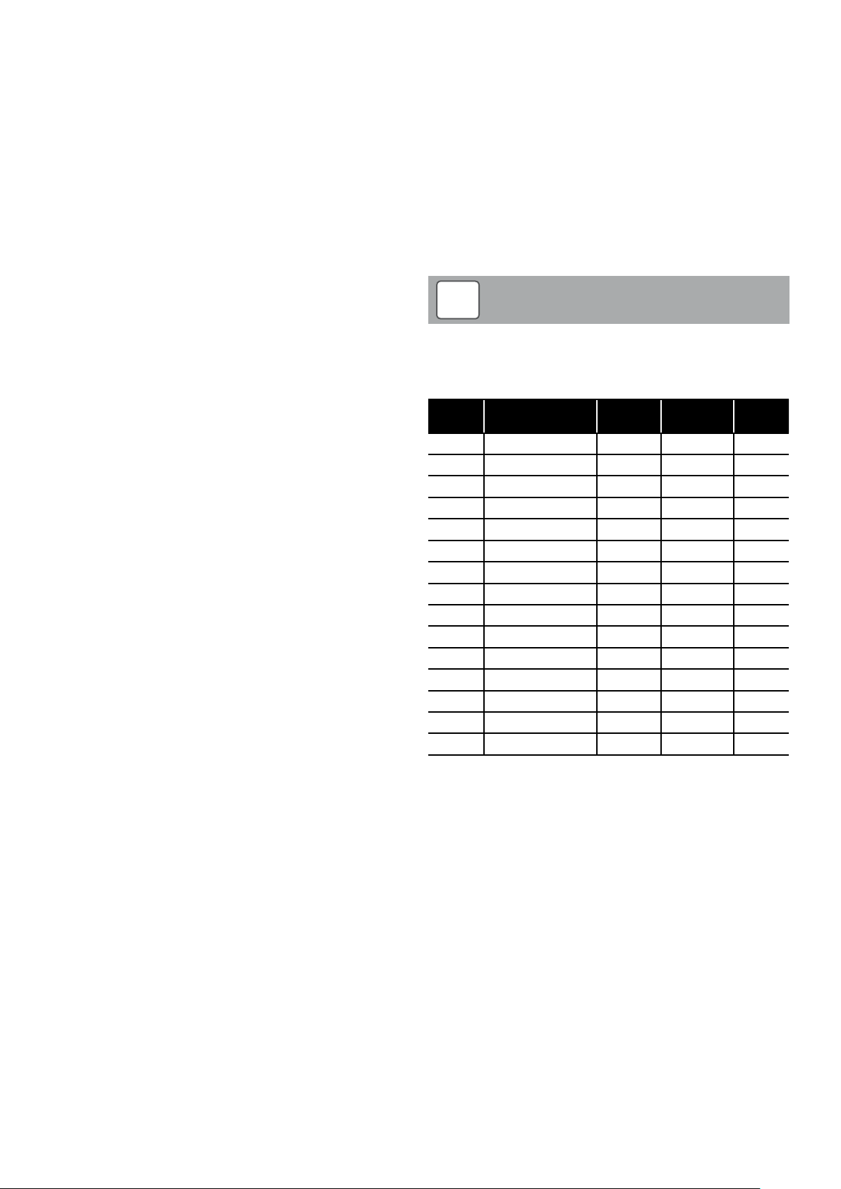
9.7 Parameter Menu
The boiler control parameters accessible to the installer are given in
the ‘Parameter Menu’ – accessed via the ‘Service Menu’.
Refer to Section 9.6 for guidance to access ‘Service Menu’ and
‘Parameter Menu’.
When in the ‘Parameter Menu’:
• Press button 1 to scroll up through parameters (in numerical
order)
• Press button 2 to scroll down through parameters (in numerical
order)
• Press button 4 to select parameter (parameter flashes)
• Press button 5 to decrease parameter or button 6 to increase
parameter
• Press button 3 to exit parameter (stops flashing)
• Press button 3 to exit boiler control parameters menu
9.7.13 Cleaning Cycles
This parameter sets the number of operations of the brazier cleaning
actuator at every brazier cleaning operation.
9.7.14 Clean Boiler
The total pellet feed auger run time before the automatic brazier
cleaning operation is activated.
9.7.15 Pause Max Power
The time between pellet feed auger operations when the burner is
operating at maximum output. Adjusting this parameter adjusts the
boiler input at maximum output, i.e. the longer the pause period the
lower the input and the shorter the pause period the higher the input.
Refer to Section 2.2 and Figures 9-1 and 9-2.
!
NOTE
9.7.1 Pause Min Power
The time between pellet feed auger operations when the burner is
operating at minimum output.
Adjusting this parameter adjusts the boiler input at minimum output,
i.e. the longer the pause period the lower the input and the shorter the
pause period the higher the input. Refer to Section 2.2 and Figures
9-1 and 9-2.
9.7.2 Temp Off H
The maximum temperature at which the burner shuts down.
9.7.3 Hysteresis Of f
The temperature above the setpoint at which the burner will stop
operating, i.e. if the water temperature exceeds the ‘Set Point’ +
‘Hysteresis Off’ value, or the ‘Temp Of f H2O’ value (see above) the
burner will stop.
9.7.4 Hysteresis On
The temperature below the setpoint at which the burner will start to
operate, i.e. the water temperature must be less than the ‘Set Point’ –
‘Hysteresis On’ value for the burner to start.
9.7.5 Setpoint
This is an alternative means of setting the boiler ‘setpoint’ temperature
between 55 and 75°C. The factory default setting is 75°C.
9.7.6 Short Cleaning Cycles
The control system will perform a short clean operation after a preset number of completed burner operations (or demands). After the
post purge is completed for the last of these burner operations, the
cleaning arm will move the brazier forwards and back once only.
The heat exchanger cleaning shaker mechanism and wash systems
are NOT operated during this short cleaning operation.
9.7.7 Fan Power Post Purge
This parameter sets the fan speed when the burner is in the post
purge mode.
9.7.8 Fan Power Lighting
This parameter sets the fan speed when the burner is in pre-load,
lighting and flame stabilisation modes.
9.7.9 Fan Power Min
This parameter sets the fan speed at minimum boiler output.
9.7.10 Fan Power Max
This parameter sets the fan speed at ma ximum boiler output.
9.7.11 Hours service
The total pellet feed auger run time before the control panel LCD
displays ‘Service’. This indicates that a service is now due.
Following every boiler ser vice this MUST be reset using the ‘Reset
Service Timers’ function. Refer to Section 9.6.4.
9.7.12 Motor Type
This parameter defines the power supply required for the cleaning
motor.
O
2
All parameters (excluding setpoint) MUST be left at the default
settings unless instructed to do so by Grant UK.
Number Parameter Units Range
6 Pause Min Power Seconds 0.5 to 60 14.0
3 Temp Off H20 °C 0 to 95 80
2 Hysteresis Off °C 0 to 20 5
1 Hysteresis On °C 0 to 20 5
0 Setpoint °C 55 to 75 75
54 Short Clean Cycles Demands 0 to 100 5
18 Fan Power Post Purge RPM 1000 to 4500 4500
17 Fan Power Lighting RPM 1000 to 4500 2000
16 Fan Power Min RPM 1000 to 4500 1600
15 Fan Power Max RPM 1000 to 4500 3100
14 Hours Ser vice Hours 1 to 1000 400
11 Motor Type - - 24V DC
9 Cleaning Cycles Cycles 1 to 20 2
8 Clean Boiler Minutes 0 to 4800 480
7 Pause Ma x Power Seconds 0.5 to 60 3.0
Table 9-5: Boiler control parameters (installer settings)
Default
settings
Section 9: Boiler OperationPage 38
Page 39
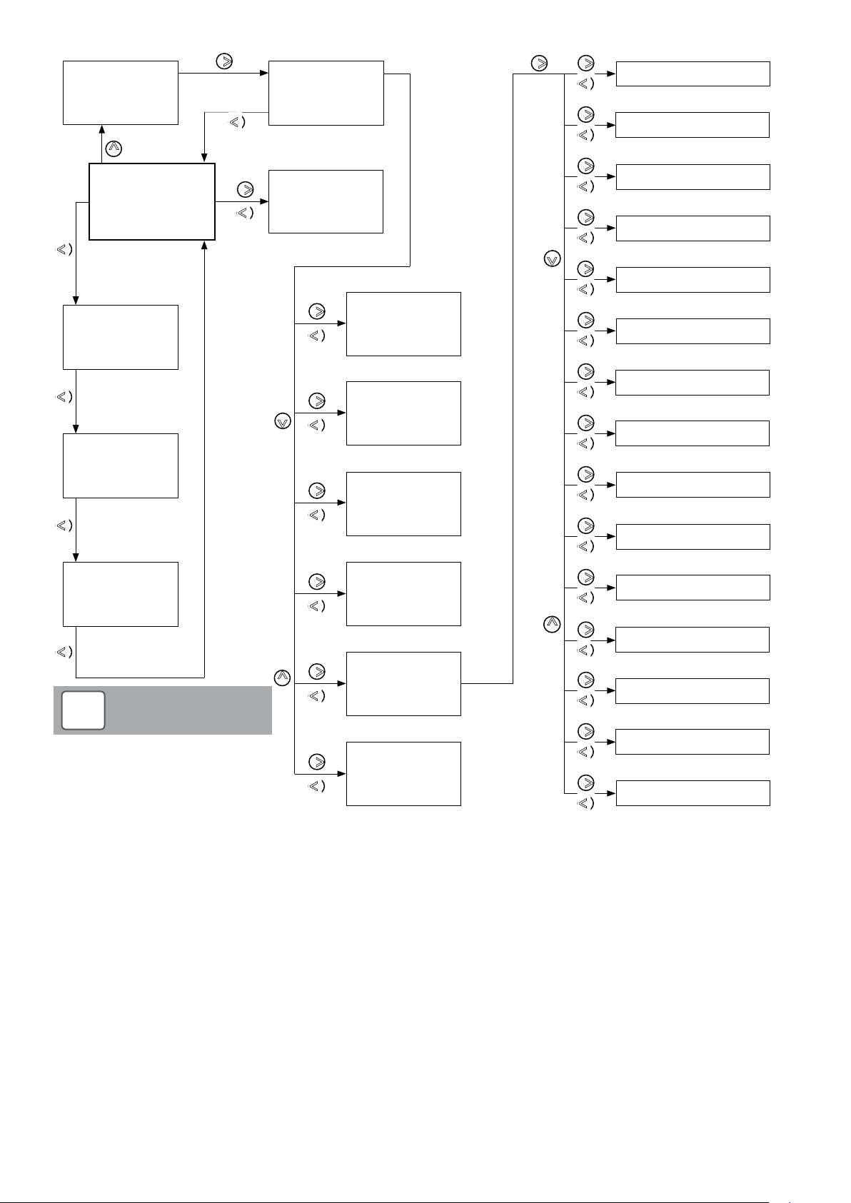
V
1
V
3
V
3
V
3
V
3
V
4
V
4
V
3
V
3
V
4
V
3
V
4
V
4
V
2
V
1
V
2
V
1
Password
V
3
V
3
V
4
V
3
V
4
V
3
V
4
V
3
V
4
V
3
V
4
V
3
V
4
V
3
V
4
V
3
V
4
V
3
V
4
V
3
V
4
V
3
V
4
V
3
V
4
V
3
V
4
V
3
V
4
V
3
V
4
V
3
V
4
V
3
V
4
V
3
V
4
V
3
V
4
Press and hold
6 Pause Min Power
Service Menu
3 Temp Off H20
2 Hysteresis Of f
Home screen
Information
Flame Lux: %
Fan Speed: RPM
Oxygen level
Target Level: %
Actual Level: %
Service information
Run Time: Hrs
Service in: Hrs
Setpoint Screen
Fan Power Select
Restore Default
Brazier Clean
Setup
Reset Service
Timers
1 Hysteresis On
0 Setpoint
54 Short Clean Cycles
18 Fan Power Post Purge
17 Fan Power Lighting
16 Fan Power Min
15 Fan Power Max
14 Hours Service
!
NOTE
After adjusting a parameter:
Press but ton 4 to confirm setting
- then press but ton 3 to return to
‘Service Menu’
Figure 9-6: Control system flowchart
Parameter Menu
Prime Auger
11 Motor Type
9 Cleaning Cycles
8 Clean Boiler
7 Pause Max Power
Section 9: Boiler Operation Page 39
Page 40

9.8 Boiler Operating Sequence
The following stages of the boiler operation are displayed on the
control panel LCD screen.
!
The number shown in brackets [X] indicates the parameter
setting – refer to Section 9.7 and Table 9-5.
Standby
Boiler not operating but ready to start in response to the following:
• A switched live input signal from control system for heating or hot
water.
• The boiler temperature drops below the ‘Setpoint’ [0] minus
‘Hysteresis On’ (5°C) temperature – if boiler temperature has
exceeded the pre-set ‘Temp Off H
• The ON/STANDBY switch on the control panel is set to the ‘ON’
position.
Wait Pre Load Brazier
Initial loading of pellets into the brazier to start the burner.
• Activated when a switched live input signal and/or temperature
drops below the pre-set ‘Setpoint’ minus ‘Hysteresis On’ value
(5°C).
• Deactivated when the pre-set ‘Preload Time’ period of 46
seconds has elapsed.
• Fan is operating at ‘Fan Power Lighting’ speed setting [17].
Lighting
Period of time allowed for pellets to light.
• Activated after ‘Wait Pre Load Brazier’ stage is completed.
• Deactivated once photocell lux reading exceeds pre-set ‘Flame
On’ setting of 20%.
• Note: ignition element remains on until end of pre-set ‘Flame
Stabilisation’ stage (10 seconds).
• Fan is operating at ‘Fan Power Lighting’ speed setting [17].
Flame Stabilisation
Period of time allowed for flame to stabilise after pellets have ignited.
• Activated after ‘Lighting’ stage is completed.
• Deactivated when the pre-set ‘Time Flame Stabilisation’ period of
10 seconds has elapsed.
• Fan is operating at ‘Fan Power Lighting’ speed setting [17].
NOTE
O’ setting (80°C).
2
Modulation Level
The boiler is now firing.
• Activated after pre-set ‘Feed Time Reduced’ period of 220
seconds has elapsed.
• Deactivated when either the demand ceases or the temperature
exceeds pre-set ‘Temp Off H
Initially, the boiler will operate at 25% output – indicated by one
segment showing on the modulation indicator.
After 25 seconds the boiler output will increase to 50% - indicated by
two segments on the modulation indicator.
After a further 25 seconds the boiler output will increase to 75% (three
segments on modulation indicator).
Finally, after a further 25 seconds the boiler output will increase to
100% (four segments on modulation indicator). The boiler is now
operating at maximum output.
After that, the boiler temperature and set point are used to determine
the required output and level of modulation. This in turn controls
the auger operating cycle. Refer to Section 9.2 for details of boiler
modulation.
• Fan is operating between ‘Fan Power Max’ [15] and ‘Fan Power
Min’ [16] speed settings to suit the modulating burner output.
Turning Of f Brazier
Burn down period to remove any pellets remaining in the brazier.
Pellet feed auger is switched off.
• Fan speed changes to pre-set ‘Fan Power Post Purge’ [18]
setting (4500rpm).
• Activated once switched live input signal is switched off or
the boiler temperature exceeds the pre-set ‘Temp Off H
setting.
• Deactivated once photocell Lux reading has dropped below preset ‘Flame Off’ setting of 4%.
Wait Post Purge
Burner fan continues to run at pre-set ‘Fan Power Post Purge’ [18]
setting (4500rpm) for a period of time after burn down is completed.
• Activated after ‘Turning off Brazier’ stage is completed.
• Deactivated when pre-set ‘Post Ventilation’ period of 120
seconds has elapsed.
O’ [3] setting (80°C).
2
O’ [3]
2
Lighting Feed Reduced
Period when pellet feed provides intermittent quantities of pellets to
the brazier to increase the flame.
The auger off period is given by the pre-set ‘Time Pause Lighting’
setting of 22 seconds and the auger on time is given by the pre-set
‘Time Load Lighting’ setting of 1 second.
• The combustion fan is operating at ‘Fan Power Max’ speed
setting [15].
• Activated after pre-set ‘Flame Stabilisation’ stage period (10
seconds) is completed.
• Deactivated when the pre-set ‘Feed Time Reduced’ period of
220 seconds has elapsed.
Section 9: Boiler OperationPage 40
Page 41
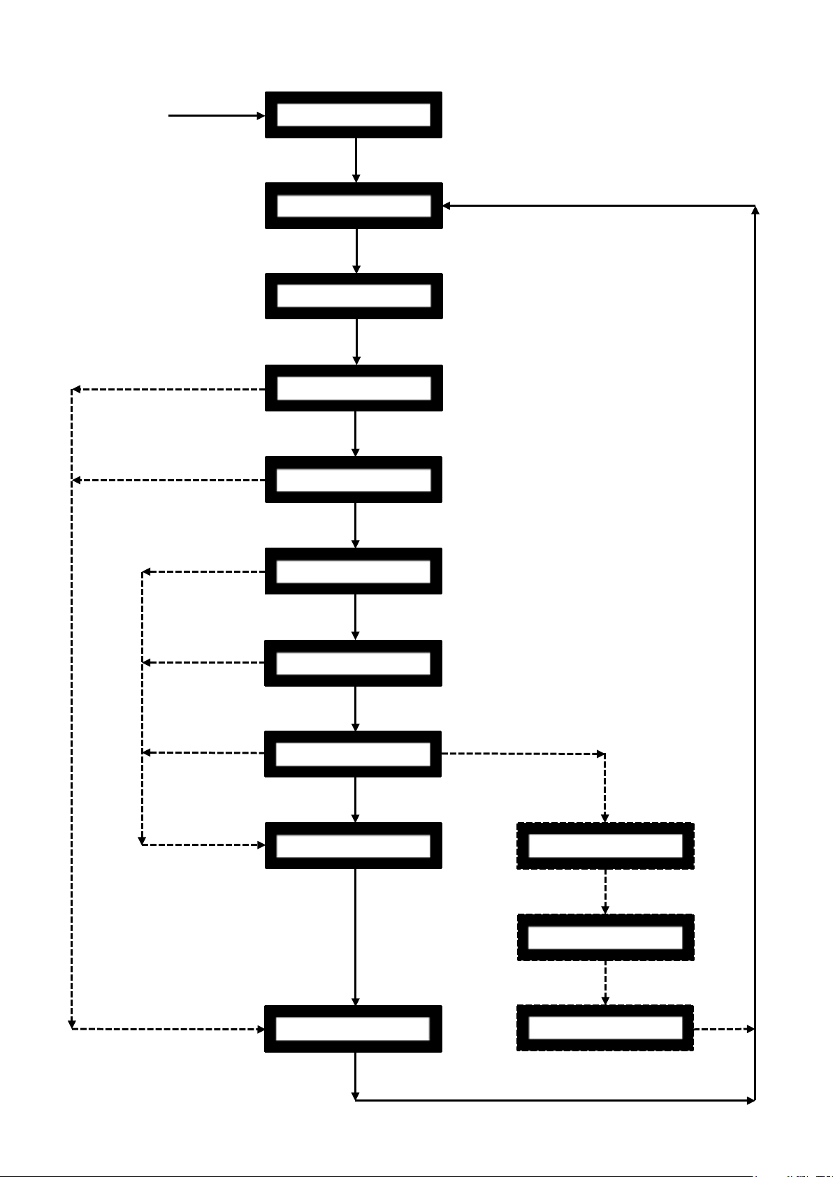
9.9 Boiler Operation Flow Chart
Time > ‘Post Ventilation’
Lux % < ‘Flame
Pellet auger run
time > 480 mins
Mains Power
Time > ‘Pre Load Time’ setting
Switched Live
Switched Live
Switched Live
Switched Live Input Off
Lux % < ‘Flame
Time > ‘Feed Time Reduced’
Lux % > ‘Flame On’ Setting (20%)
Time > ‘Time Flame Stabilisation’
Fan Proving Check OK
Temp < (Set point – Temp Delta)
& Switched Live Input on
Switched Live Input Off
Wait Pre Load Brazier
Fan Proving Check
Lighting Feed
Reduced
to Boiler On
Boiler Clean
Standby
Wait Pre Load Brazier
(46 seconds)
Lighting
Input Off
Input Off
Input Off
Flame Stabilisation
Setting (10 seconds)
Setting (220 seconds)
Modulation Level
Turning Off Brazier
Off’ Setting (4%)
Turning Off Brazier
Off’ Setting (4%)
Wait Post Purge
Setting (120 seconds)
Wait Post Purge
Figure 9-7: Boiler control sequence flow chart
Section 9: Boiler Operation Page 41
Boiler Clean
Page 42
10 Side Pellet Store
10.1 General
The optional side pellet store for the Grant External wood pellet boiler
is designed to provide an increased storage capacity, allowing the
boiler to run for longer periods before topping-up is required.
The capacity of the side pellet store is 140kg. With the 80kg capacity
of the boiler pellet hopper this gives a total pellet storage capacity of
220kg.
This side pellet store is the same external design as the External
Vecta boiler and is designed to be located at the right hand side of the
boiler only. It incorporates an auger to automatically transfer pellets
from the side pellet store to the boiler pellet store when activated by
the contents switch. Refer to Section 10.2.
!
This side pellet store can only be fit ted on the right hand side
of the Grant External Vecta boiler. It CANNOT be fit ted on the
left hand side of the boiler under any circumstances.
The side pellet store auger pipe is supplied in two pieces. The lower
section is supplied factory-fitted in the bottom of the side pellet store
along with the auger motor and spiral. The end of the auger spiral is
secured to the side pellet store by the packaging.
NOTE
10.2 Operation
When fitted to the boiler, the side pellet store auger extends from
within the side pellet store into the boiler pellet hopper.
The side pellet store is connected to the electrical controls of the
boiler. When the diaphragm contents switch fitted to the boiler pellet
hopper detects a low fuel level the side pellet store auger will be
automatically operated.
The control panel LCD screen will show ‘Fuel Low Warning’ and the
Remote Grant logo indicator (located inside the house) will also flash
(slowly) to indicate that the pellet level in the boiler hopper has fallen
to the pre-set minimum.
Pellets will be transferred from the side pellet store to the boiler pellet
hopper. This will continue until the contents switch in the boiler pellet
hopper is satisfied, at which point the side pellet store auger will stop.
Both the ‘Fuel Low Warning’ on the control panel LCD screen and the
slow flashing Grant logo indicator will be automatically cancelled.
!
The boiler pellet hopper will not be completely filled by the side
pellet store. The auger will only transfer pellets to the boiler
pellet hopper until the contents switch is satisfied.
NOTE
!
Great care must be taken when removing the packaging
holding the auger spira as the end of the auger spiral can
spring out and cause injury.
The auger extension pipe is supplied loose and must be fitted as
described in these installation instructions. Refer to Section 10.3 for
full details.
WARNING
The side pellet store is also fitted with a diaphragm contents switch.
The side pellet store auger will only operate when this contents switch
indicates there are sufficient pellets in the side pellet store. If this level
drops below the minimum to activate the contents switch, the auger
will no longer operate to transfer pellets to the boiler pellet hopper.
In this instance, when the boiler pellet hopper contents switch detects
a low fuel level no pellets will be transferred to the boiler pellet hopper.
The control panel LCD screen will show ‘Fuel Low Warning’ and the
Remote Grant logo indicator (located inside the house) will also flash
(slowly) to indicate that the pellet level in the boiler hopper has fallen
to the pre-set minimum.
If the boiler pellet hopper is not topped up at this point, the boiler
will continue to operate for a short period before the burner is
automatically stopped.
Topping up the boiler pellet hopper with at least 20kg of pellets will
operate the contents switch and automatically re-start the burner (as
long as there is a demand present for the boiler to run). Both the ‘Fuel
Low Warning’ on the boiler control panel LCD screen and the slow
flashing Grant logo indicator will be automatically cancelled.
!
In order to ma ximise the combined pellet storage capacity of
the boiler and side pellet store, it is recommended that both the
boiler pellet hopper and the side pellet store are filled to the
top when topping-up.
NOTE
Section 10: Side Pellet StorePage 42
Page 43

10.3 Installation
10.3.1 Boiler Installation
Install the boiler in the required location allowing sufficient room for
the installation of the side pellet store. Refer to Section 2.4 for details
of dimensions and clearances required for the boiler and side pellet
store.
10.3.2 Preparing the Boiler
!
Do NOT position the side pellet store alongside the boiler at
this stage.
Prepare the boiler for the installation of the side pellet store as follows:
1. Ensure that the electrical supply to the boiler is isolated.
2. Open the hinged hopper lid on the boiler.
3. Undo and remove the three screws along the top edge of the
right hand side panel. Refer to Figure 10-1. Keep these screws
for re-fitting later.
NOTE
!
It is NOT necessary to unscrew and remove the diaphragm seal
plate to make this hole in the side of the boiler pellet hopper.
Figure 10-3: Removing the knockout in the pellet hopper
!
It is NOT necessary to unscrew and remove the diaphragm seal
plate to make this hole in the side of the boiler pellet hopper.
8. Then, working through the rectangular opening, use a
screwdriver to prise the circular part from the opening, remove
it from the boiler and discard. This will leave the opening in the
boiler pellet hopper and the rubber diaphragm seal through
which the auger pipe will be fitted.
9. Undo and remove the t wo hex head screws from along the
bottom edge of the boiler right hand side panel. Refer to Figure
10-4. Keep these screws for re-fitting later.
NOTE
NOTE
Figure 10-1: Removing the three screws
4. Undo the t wo screws (one on each side) and remove the access
cover from the top of the boiler. Refer to Figure 11-2.
5. Remove the pellet hopper grille. Pull up the front edge. Lif t the
grille off the three tabs in the slots along at the rear edge, and
remove it from the boiler. Refer to Figure 10-2.
Figure 10-2: Removing the pellet hopper grille
6. Ensure that the boiler pellet hopper is empt y of pellets. If not
remove all pellets before proceeding any fur ther.
7. Remove the pre-cut knock-out in the lower right hand side of the
boiler pellet hopper to provide the hole for the side pellet store
auger.
To do this, use a hammer to strike the pre-cut round section from
within the pellet hopper just enough to start to break it out of the
panel. Refer to Figure 10-3.
Figure 10-4: Removing the two hex head screws
Section 10: Side Pellet Store Page 43
Page 44

10.3.3 Side Pellet Store Installation
Install the side pellet store using the following procedure:
1. Undo and remove the three screws along the top edge of the
left hand side panel of the side pellet store. Refer to Figure 10-5.
Keep these screws for re-fitting later.
Figure 10-5: Removing the three screws from the side store
2. Remove the front panel from the side pellet store. Undo and
remove the four panel retaining screws at the top edge of the
front panel. Refer to Figure 10-6. Lift the front panel upwards and
off the side pellet store casing.
4. Whilst firmly holding the end of the auger spiral in position, cut
and remove the packaging securing it to the side pellet store.
!
The end of the auger spiral MUST be FIRMLY held to prevent
it from springing out and possibly causing injur y when the
packaging is cut and removed.
5.
Slacken the clamp bolt on the auger pipe socket so that the
auger extension pipe can be fitted. Refer to Figure 10-8 for
location of auger pipe clamp bolt.
Clamp bolt
WARNING
Figure 10-6: Removing the four screws and front panel
3. Remove the centre section of the grille inside the side pellet
store. Undo the single fixing screw and lift the centre section
away from the surrounding part of the grille. Refer to Figure 10-7.
Figure 10-8: Location of auger pipe clamp bolt
6. Manoeuvre the side pellet store into position alongside right hand
side of the boiler, carefully feeding the end of the auger spiral
through the hole in the diaphragm seal plate in the side of the
boiler pellet hopper.
!
Leave a gap of approximately 10mm bet ween the spacer
channel and the side of the boiler at this stage of the
installation.
7.
Lubricate the outer surface of the auger extension pipe (at the
unpainted end) with some silicone grease, washing up liquid or
similar.
8. Working from within the boiler hopper, locate the unpainted end
of the auger extension pipe over the end of the auger spiral.
9. Looking through the 10mm gap between the boiler and side
pellet store spacer channel, carefully push the end of the auger
extension pipe through the diaphragm seal and into the auger
pipe socket.
10. Ensure it is fully pushed in and then secure in place by tightening
the auger pipe clamp bolt.
NOTE
Figure 10-7: Removing the single fixing screw and grille
!
Do not over tighten the clamp bolt as this can distort the auger
extension pipe and prevent the auger spiral from rotating
freely.
11.
Now push the side pellet store into its final position with the left
side of the side pellet store hard up against the right hand side of
the boiler casing.
12. From inside the side pellet store enclosure; re-fit the two hex
head screws through the bottom left hand edge of the side pellet
NOTE
Section 10: Side Pellet StorePage 44
Page 45

store and into the boiler casing. Leave finger tight at this stage.
Refer to Figure 10-9.
Figure 10-9: Refitting the two hex head screws
13. Fit the top joining channel between the boiler and side pellet
store with the V-shaped tongue facing towards the back of
the boiler/side store. Carefully slide the jointing channel in the
V-shaped groove formed bet ween the t wo boilers. Refer to
Figure 10-10.
Figure 10-11: Fitting the top joining channel screws
16. Re-fit the centre section of the grille inside the side pellet store
and secure with the single fixing screw previously removed. Refer
to Figure 10-7.
17. Finally, from inside the side pellet store; tighten the two hex head
screws to secure the bottom of the side pellet store to the boiler
casing.
Figure 10-10: Fitting the top joining channel
14. Push the channel as far back as possible – until the fixing holes
in the flat sections (on each side of the V) line up with the holes
in the top edges of the side panels on both the boiler and side
pellet store.
15. Secure the channel in place using the six screws previously
removed from the top edges of the side panels. Refer to Figure
10-11.
!
The hinged lids on both the boiler and side pellet store are
each fitted with a cut-out switch and BOTH must be closed in
order for the boiler to operate.
NOTE
Section 10: Side Pellet Store Page 45
Page 46
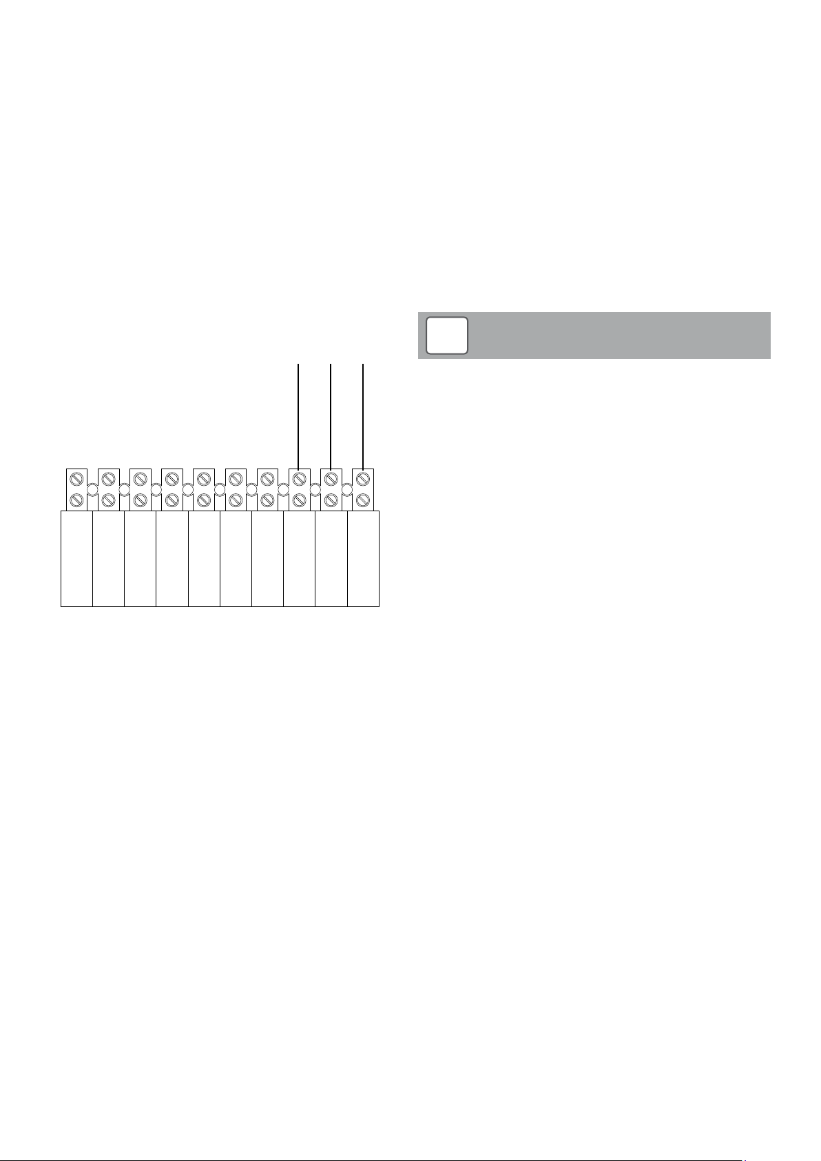
10.4 Electrical Connections
2
3
LIVE
1
10.4.1 Pellet side store contents switch
1. Feed the white cable from the side pellet store contents switch
through the opening between the side pellet store and the boiler
and into the boiler casing.
2. Route it under the hopper and around to the boiler wiring terminal
block at the left front of the boiler.
3. Remove the terminal block cover (refer to Section 8.2) and feed
the cable through the right hand cable clamp.
4. Connect the cable to the terminal block as follows (Refer to
Figure 10-12):
• Blue wire – ‘side store neutral’
• Green/Yellow wire – ‘side store ear th’
• Brown wire – ‘side store live’
5. Tighten the cable clamp to secure the cable and re-fit the
terminal block cover.
10.4.2 Pellet side store lid cut-out switch
1. Locate the in-line male and female connectors nex t to the boiler
lid cut-out switch (under the upper front edge of the boiler front
panel in the centre) and carefully separate the two connectors.
2. Feed the grey cable, from the side pellet store lid cut-out switch,
through the opening between the side pellet store and the boiler
and into the boiler casing.
3. Route the cable up inside the right hand boiler side panel. Pass
it through the two cable loops (under the upper front edge of the
boiler front panel at the right hand side).
4. First connect the male connector on the grey cable to the female
connector from the boiler lid cut-out switch.
5. Then connect the female connector on the grey cable to the male
connector from the boiler lid cut-out switch. The boiler lid cut-out
switch is now connected in series with the side pellet store lid
cut-out switch.
Cable from side pellet store contents switch
Blue
Green/Yellow
SWITCHED
LIVE
PERMANENT
LIVE
NEUTRAL
Figure 10-12: Pellet side store electrical connection diagram
EARTH
SIDE STORE
SIDE STORE
NEUTRAL
EARTH
Brown
SIDE STORE
!
If either the boiler hinged hopper lid OR the side pellet store
lid is opened for longer than 5 seconds, whilst the boiler is
operating, the burner will be automatically stopped. Closing the
hopper lid resets the cut-out switch and the boiler will restart.
Refer to Section 11.4 for details of the hopper lid cut-out switch
6.
Re-fit the front panel to the side pellet store. First engage
the three tabs on the bottom edge of the front panel into the
corresponding slots in the bottom of the side pellet store. Then
secure it in place by re-fitting the four panel retaining screws
previously removed.
NOTE
Section 10: Side Pellet StorePage 46
Page 47

10.5 Commissioning the Side Pellet Store
Following installation, the operation of the side pellet store auger must
be checked using the following procedure:
1. Open the hinged lid and put 30kg of pellets (e.g. three 10kg
bags) in the side pellet store.
2. Close both the side pellet store and boiler hinged lids.
3. Check that the ON/STANDBY switch on the boiler control panel is
set to STANDBY.
4. Switch the power supply to the boiler to ON. The boiler will go
through the automatic cleaning operation. Refer to Section 9.3 for
details.
5. The boiler control panel LCD will flash with the message ‘Low
Fuel Warning’, and the remote Grant Logo Indicator will also flash
slowly, indicating a low pellet level and that the boiler hopper
needs to be topped-up.
DO NOT PUT PELLETS INTO THE BOILER PELLET
HOPPER AT THIS TIME.
6. The side pellet store auger should star t operating to transfer
pellets from the side pellet store into the boiler pellet hopper.
7. Wait for about five minutes and then briefly (i.e. for less than five
seconds) open the hinged hopper lid on the boiler. There should
be pellets in the bottom of the hopper.
8. Close the lid immediately and leave the side pellet store auger
running until enough pellets are transferred into the boiler pellet
hopper to satisfy the contents switch.
9. At this point both the remote Grant Logo Indicator and ‘Low
Fuel Warning’ message on the boiler control panel LCD will stop
flashing.
10. Both the boiler hopper and the side pellet store can now be filled
to the top with pellets. Use only ENPlus Grade A1 pellets that
comply with BS EN ISO 17225-2:2014.
!
The operation of the side pellet store auger MUST be checked
BEFORE filling the boiler pellet hopper with pellets.
NOTE
Section 10: Side Pellet Store Page 47
Page 48
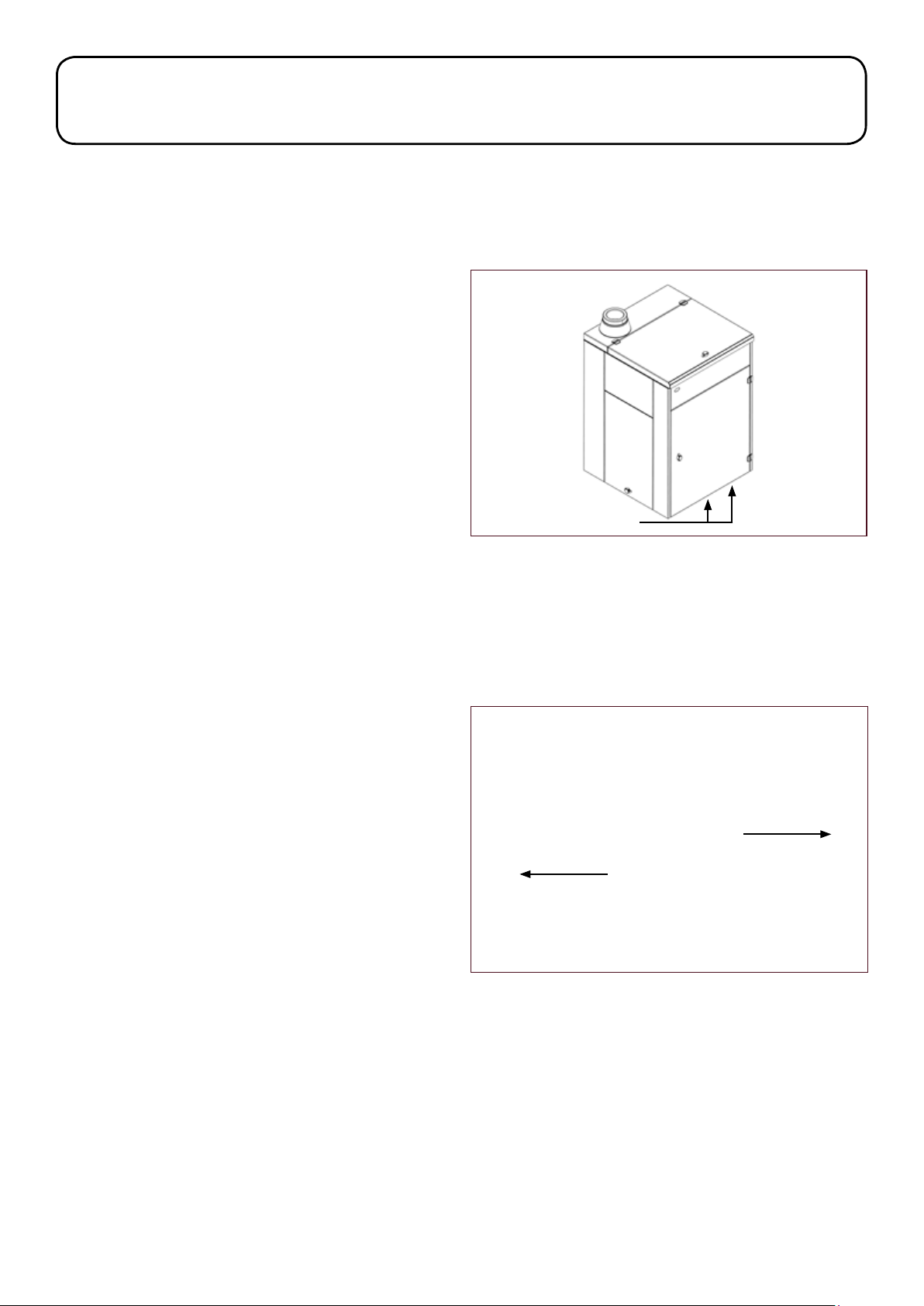
11 Commissioning
It is important that the following commissioning procedure is carried
out following installation to ensure safe and efficient operation of the
boiler.
11.1 Equipment Required
To carr y out a complete and comprehensive commissioning of the
Grant Vecta wood pellet boiler the following equipment is required:
• Electronic draught meter.
• Flue gas analyser (with ‘wood pellet’ fuel setting).
11.2 Preliminar y Inspection
Before switching on the power supply to the boiler, the following must
be checked:
11.2.1 Heating System
Check the following:
• That corrosion inhibitor and, where necessary antifreeze, is
present in the system water. Refer to Section 4.7.
• That a magnetic in-line filter has been fitted in the system return.
Refer to Section 4.7.
• Both the boiler and heating system is filled and vented.
• On sealed systems the expansion vessel charge pressure is
correct and system is filled to correct pressure.
• For any leaks at joints, fittings, etc.
11.2.2 Electrical Connections
Check the following:
• The electrical connections to the boiler are correct. Refer to
Figure 8-7.
11.2.6 Combustion Ventilation
Check that the combustion air inlet to the boiler along the lower front
edge of the boiler front door is unobstructed. If necessar y remove any
obstructions, e.g. leaves, etc.
Check that the combustion air inlet to the burner, located in the font of
the boiler, is unobstructed. Refer to Figure 11-1.
Boiler air inlet
Figure 11-1: Air inlet
11.3 Boiler
11.3.1 Control Thermistor and Overheat Thermostat
• Isolate the electrical supply to the boiler.
• Open the hinged hopper lid on the boiler.
• Undo the two screws (one on each side) and remove the access
cover from the top of the boiler. Refer to Figure 11-2.
11.2.3 Wash-down System
Check the following:
• The inlet to the wash-down system (located at the bottom rear
corner of the left side panel) is connected to an uninterrupted
mains water supply.
• All valves in this water supply are open.
11.2.4 Condensate Disposal System
Check the following:
• The condensate trap (supplied with the boiler) and condensate
disposal pipework has been fitted correctly. Refer to Section 5.
• If a condensate pump is fitted, that a condensate holding tank
of at least 40 litres capacity has also been installed. Refer to
Section 5.
11.2.5 Flue System
Check the following:
• The correct flue system has been used. Only the Grant ‘Biomass’
flue system should be used.
• The flue system is correctly connected to the boiler flue outlet.
Refer to Section 7.4.
• The boiler combustion air inlet along the bottom of the front door
is clear and unobstructed.
• The flue system conforms to the relevant requirements of
The Building Regulations Approved Document J for solid fuel
appliances.
Figure 11-2: Removing the access cover
• Remove the pellet hopper grille. Pull up the front edge. Lift the
grille off the three tabs in the slots along at the rear edge, and
remove it from the boiler.
• Ensure that the boiler pellet hopper is empty of pellets. If not
remove all pellets before proceeding any fur ther.
• The pocket, containing both the boiler control thermistor sensor
and overheat thermostat bulb, is located in the upper left front
of the boiler, to the left of the heat exchanger housing. Refer to
Figure 11-3.
Section 11: CommissioningPage 48
Page 49
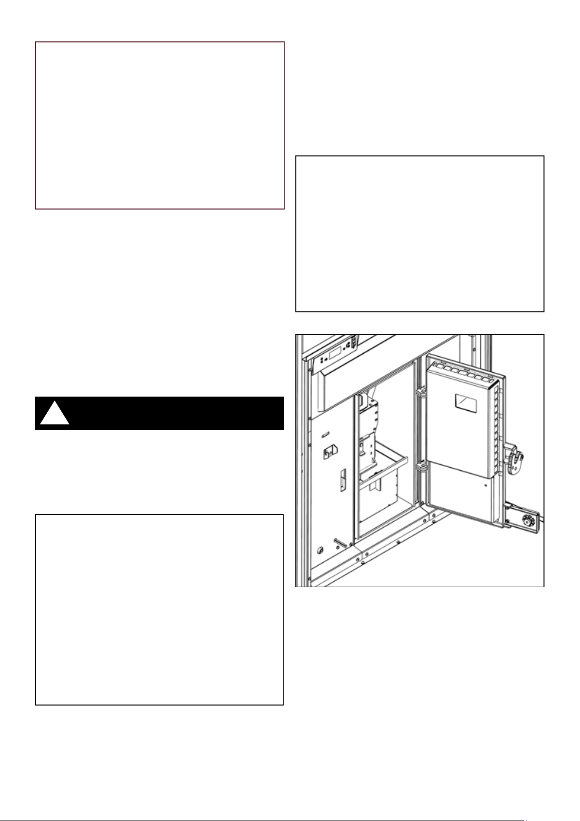
Figure 11-3: Location of boiler control thermistor sensor and overheat
thermostat bulb
Check the following:
• That both the overheat thermostat bulb and control thermistor
probe bulb are fully inserted in the boiler waterway pocket and
the retaining clip is fitted.
• The condition of thermistor cable and thermostat capillary, i.e.
not damaged, broken or kinked.
Check the following:
• The ash pan is empty and correctly located on the base of the
combustion chamber
• The horizontal and vertical baffles are correctly fitted in the rear
of the combustion chamber.
• The burner flame pot is correctly located in the top of the burner.
• Close the combustion chamber door.
• Remove the multi-purpose tool from the door catch and hang
it back on the hook provided on the panel to the lef t of the
combustion chamber door.
11.3.2 Combustion Chamber
Open the front door. First unlock and remove the padlock (if fitted),
rotate the knob of the catch clockwise to unlatch and fully open the
front door.
Switch the electrical isolator to OFF. Refer to Figure 11-4 for location
of isolator.
!
The electrical isolator switch does NOT isolate the electricity
supply to the boiler. The power supply to the boiler wiring
terminal block will still be live when the isolator is set to OFF.
If required, the electrical supply to boiler should be isolated at
the fused spur supplying the heating system and controls.
WARNING
Figure 11-5: Opening combustion chamber
Figure 11-6: Combustion chamber door open
Figure 11-4: Location of electrical isolator
Fit the multi-purpose tool (provided with the boiler) into slot in door
catch. Refer to Figure 11-5.
Lift the tool handle to release the door catch and fully open the
combustion chamber door of the boiler. Refer to Figure 11-6.
Section 11: Commissioning Page 49
Page 50
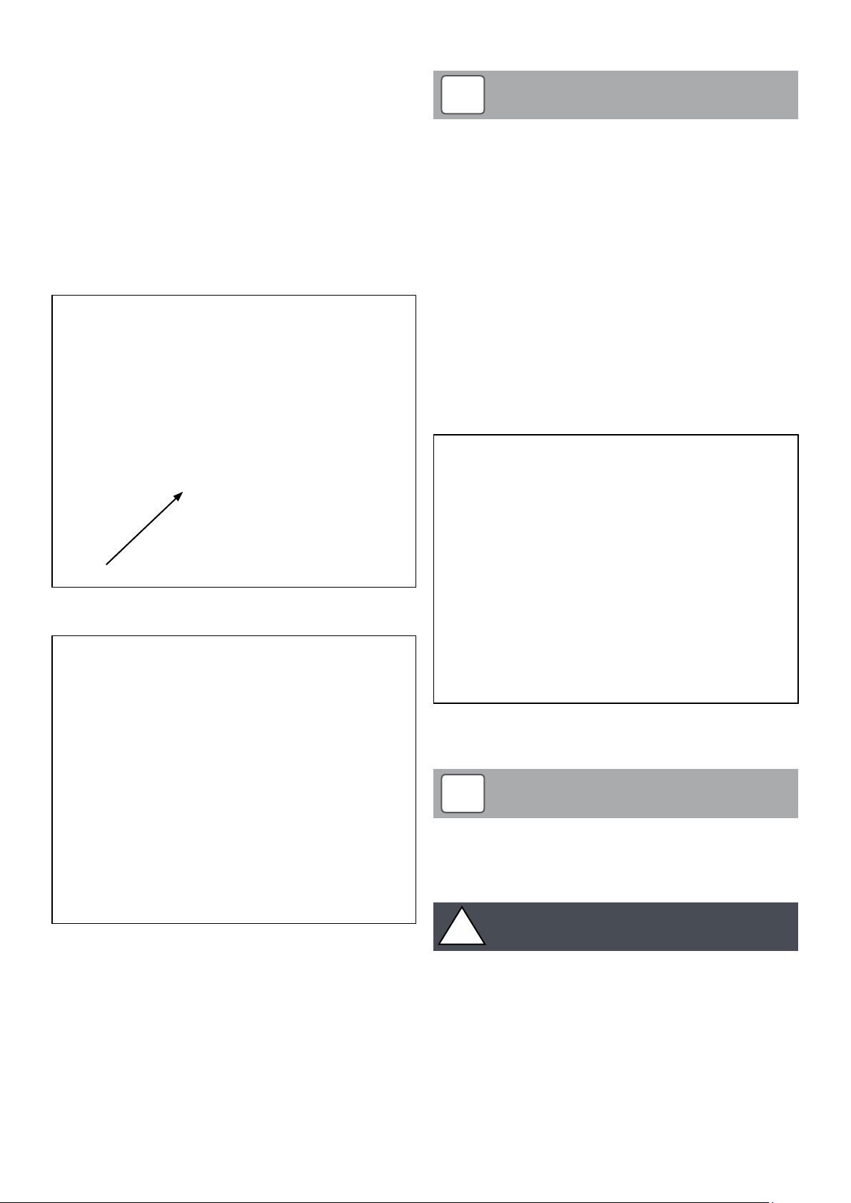
11.3.3 Primary Heat Exchanger
To gain access to the top of the heat exchanger:
• With hinged hopper lid open and top access cover removed (as
per Section 11.3.1)
• Shut off the cold water supply to wash system.
• Disconnect the water supply hose from the wash system. Refer
to Figure 12-2.
• Unscrew and remove the five nuts (and washers) securing the
heat exchanger cover and remove it from the top of the heat
exchanger. Refer to Figure 11-7.
• Check that the spiral baffles in the heat exchanger are all in
place. Lift and drop each one to check all are free to move in
their respective tubes. Refer to Figures 11-8.
11.3.4 Secondary Heat Exchanger
!
There are two dif ferent t ypes of spiral baffle fitted to the
secondary heat exchanger.
The spiral baffles fitted to the right hand side have a 2½ turn
spiral and are dif ferent to those on the lef t hand side which
have 4½ turn spiral.
Whenever these are removed, it is important that they are refitted in the correct side of the secondary heat exchanger.
With the hinged hopper lid open and both top access cover and heat
exchanger cover removed (as per Section 11.3.3).
• Check that the spiral baffles in the secondary heat exchanger are
all in place.
• Check that all spiral baffles are correctly aligned with the top
edges running ‘front to back’. Refer to Figure 11.9.
• Refit the heat exchanger cover to the top of the heat exchangers
and secure with the nuts previously removed. Do not over tighten
• Re-connect water supply hose to connection on wash system
manifold. Refer to Figure 12-2.
NOTE
Lambda sensor
Figure 11-7: Heat exchanger cover and Lambda sensor position
Figure 11-8: Primary heat exchanger spirals
Figure 11-9: Secondary heat exchanger spirals
11.3.5 Boiler Pellet Hopper
!
If the optional side pellet store is fit ted, the operation of the
side pellet store auger MUST be checked BEFORE filling the
boiler pellet hopper. Refer to Section 10.5 for details.
!
Before filling the boiler pellet hopper with pellets for the first
time, ensure that hopper is empty of all other debris or objects,
e.g. screws, nuts, etc.
NOTE
CAUTION
•
Check that the pellet hopper is full of pellets. Fill the hopper with
pellets by hand from bags. Ensure that only EN Plus Grade A1
pellets, that comply with BS EN ISO 17225-2:2014, are used with
the Grant Vecta boiler. Refer to Section 3 for details.
Section 11: CommissioningPage 50
Page 51

11.4 Hopper Lid Cut-out Switch
With the power supply to the boiler switched OFF:
• Set the ON/STANDBY switch on the boiler to STANDBY and
switch the power to the boiler ON.
• Open the hinged hopper lid and wait.
• After 5 seconds, the control panel LCD screen will flash and
indicate a ‘Hopper Lid Open’ (Error Code 16) fault.
• Wait for at least 15 seconds for the fire damper in the pellet feed
system to fully close.
• Close the pellet hopper lid. The control panel LCD screen will
flash and indicate a ‘Safety Flap Closed’ (Error Code 22) fault.
Wait for 30 seconds, for the fire damper to re-open. The fault
message will automatically disappear from the LCD screen and
‘Standby’ will be displayed.
11.7 Lighting the Boiler
!
BEFORE attempting to light the boiler, open the combustion
chamber door and remove ALL pellets from the burner. Close
the combustion chamber door and proceed to lighting the
boiler.
Ensure that the electrical supply to the boiler is switched ON and that
the heating system controls are operating and are calling for heat. Set
the burner ON/STANDBY switch to ON. The fan will start and pellets
will be delivered to the burner. Refer to Section 9.1 for details of the
burner start-up, running and shut down sequences.
NOTE
11.5 Control Set tings
The boiler comes with the control system pre-set from the factory.
However, the burner settings should be checked as part of the
commissioning process and recorded on the Commissioning Report
form. Refer to Section 10-12.
With the electrical power to the boiler switched ON and the burner
ON/STANDBY switch set to STANDBY,
• Check ALL control settings in the ‘Parameter Menu’. Refer
to Section 9.7 for details of how to access and check these
settings.
• Set the boiler ‘Set Point’ temperature using buttons 4, 5 and 6
on the boiler control panel. Refer to Section 9.5 for detail on how
to adjust boiler setpoint temperature. Refer to Section 1.1 for
required flow and return temperatures.
11.6 Priming the Pellet Feed Auger
The pellet feed auger MUST be fully primed BEFORE attempting to
start the boiler. To prime the auger proceed as follows;
• Check the burner ON/STANDBY switch is set to STANDBY.
• Access the ‘Service Menu’ (refer to Section 9.6 for guidance).
• When in the ‘Service Menu’ - press button 2 to scroll down to
‘Prime Auger’ function.
• Press button 4 to select ‘Prime Auger’ function.
This function has a pre-set maximum time of 5 minutes.
• Press and hold button 4 for at least 3 minutes or until a steady
stream of pellets are heard dropping into the burner.
• The control panel LCD screen shows the countdown (time
remaining) from 5 minute start point
• If necessary the ‘Prime Auger’ function can be repeated, using
the above procedure.
If the priming is stopped during the 5 minutes, the timer automatically
resets to 5 minutes (and this is displayed on the boiler control panel
LCD screen).
!
If the boiler ON/STANDBY switch is set to STANDBY during
the initial pellet pre-load period, the pellet feed will stop. The
burner may go into post purge with error message ‘False flame’
(and fault code 19) displayed on the control panel LCD screen.
The burner will complete the shut-down sequence before it can
start-up again, even if the ON/STANDBY switch is reset to ON.
If the ON/STANDBY switch is set to STANDBY during the
start-up sequence, but AFTER the pre-load is finished, then
the burner will immediately enter and complete the shut-down
sequence before it can star t-up again, even if the ON/STANDBY
switch is reset to ON.
After completing the start-up sequence, the burner should be firing
at maximum output. ‘Modulation Level’ is displayed on the burner
control panel LCD screen with all four segments showing (i.e. burner
firing at 100% output).
!
The interlock on the combustion chamber door interrupts the
power supply to the burner if the door is opened. IT DOES NOT
IMMEDIATELY EXTINGUISH THE BURNER FLAME. If the burner
door is opened whilst the burner is firing, there can still be a
large uncontrolled flame from the brazier.
NOTE
WARNING
Section 11: Commissioning Page 51
Page 52
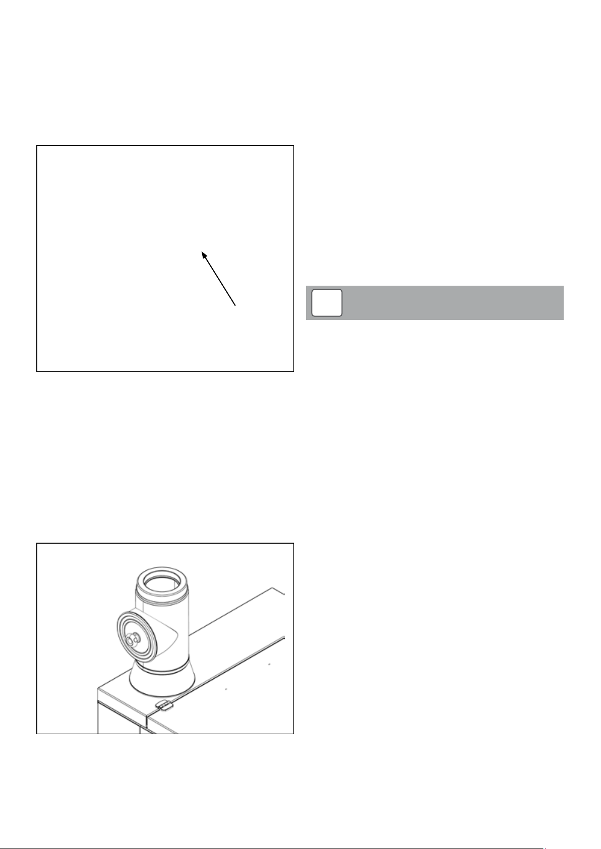
11.8 Combustion Chamber Draught
The combustion chamber draught must be checked and adjusted
(where necessary) as follows:
• Ensure the control panel LCD screen is showing ‘Modulation’
and the Modulation Indicator (in the lower right corner of display)
is showing FOUR segments (100% output).
• Remove the screw from the draught test point, located to the
bottom left corner of the combustion chamber door. Refer to
Figure 11-10.
• Ensure the control panel LCD screen is showing ‘Modulation’ and
the Modulation Indicator (in the lower right corner of display) is
showing FOUR segments (100% output).
• There is no combustion test point on the boiler. A test point (and
flue access door) is provided in the Inspection Pipe (product
code: WPBOM/IP) that MUST be fitted to the boiler flue outlet.
• To access the flue inspection hatch, remove the circular outer
cover. To do this, turn the knob in the centre of the outer cover
approximately one turn anticlockwise and pull the cover away
from the inspection pipe. Refer to Figure 11-11.
• Remove the flue inspection hatch. Turn the knurled knob (in the
centre of the hatch) approximately one turn anticlockwise, pull
the hatch out of the flue and inspect the inside of the flue system.
• Unscrew and remove the test point screw to insert combustion
analyser probe.
• Monitor the %CO2 for a few minutes to see the ma ximum and
minimum values reached.
• The %CO2 measured should range between a minimum of 8%
and a maximum of 12%.
• If the %CO2 measured is outside of this range, set the ON/
STANDBY switch to STANDBY and contact Grant UK for advice.
Draught
test
point
Figure 11-10: Draught test point
• Ensure that the draught test point hole is open right through into
the combustion chamber. If necessar y push a suitably sized
screwdriver through to ensure that the hole is clear.
• Using an electronic draught gauge - check zero on the draught
gauge, insert the end of the draught gauge sample tube into the
test point on the door. Ensure that it is fully pushed through the
door insulation and into the combustion chamber.
• A draught reading of between 0.75 and 1.25 mbar is required.
If the draught reading is outside of this range, set the ON/
STANDBY switch to STANDBY and contact Grant UK for advice.
11.9 Flue Gas Analysis
!
Always replace the test point screw and outer access cover on
the flue inspection pipe following combustion testing. Do not
over tighten test point screw.
NOTE
11.10 Customer Handover
The customer/user must be informed of the correct operation and use
of their Grant Vecta wood pellet boiler installation. This must include
the following information:
• The use of the boiler controls – how to switch the boiler off and
on, as required. Refer customer to the user guide supplied with
the boiler.
• The use of the heating system controls – how to set the
programmer, room and cylinder thermostats, etc.
• The importance of using the correct type of wood pellet.
• The need to routinely check the pellet level in the pellet hopper
and how to re-fill it.
• How to access the ash pan and the need to periodically empt y
the ash pan. Refer to Section 1.6 and the user guide.
• The need to have the boiler ser viced either annually or when
‘Service’ is shown on the boiler control panel display (whichever
comes first). Refer to Section 1.6 and the user guide.
• That servicing should only be carried out by a Grant trained
installer.
Figure 11-11: Combustion test point
Once the combustion chamber draught has been checked, as
described in Section 11.8, the %CO2 in the flue gases must be
checked as follows:
• Allow the boiler to run for a period of at least 15 minutes, until the
boiler and flue system are warmed up.
11.11 Commissioning Report Form
The Commissioning Report form (supplied with the boiler) must be
completed at the end of the commissioning process. Refer to Section
4.8.
The following information must be entered on the form:
• Boiler details (model, serial number, etc.)
• Combustion readings
• Installation details
• Burner settings
• Customer handover details
The completed form must be signed by both installer and customer/
user.
A copy of the completed form must be left with the customer/user,
one must be returned to Grant UK and the remaining third copy
retained by the Installer. Refer to Section 4.8.
Section 11: CommissioningPage 52
Page 53

11.12 Commissioning Check List
The following checklist must be used in conjunction with the
preceding information given in this section:
Preliminary Inspection Tick box
Heating system
Electrical connections
Condensate disposal
Flue system
Combustion ventilation
Boiler
Control panel
Overheat and temperature control thermistor
Combustion chamber
Heat exchanger – primary
Heat exchanger – secondary
!
There are two dif ferent t ypes of spiral baffle fitted to the
secondary heat exchanger.
The spiral baffles fitted to the right hand side have a 2½ turn
spiral and are dif ferent to those on the lef t hand side which
have 4½ turn spiral.
Whenever these are removed, it is important that they are refitted in the correct side of the secondary heat exchanger.
NOTE
Notes
Pellet Hopper
Pellets
Safety Device Checks
Hopper cover cut-out switch
Combustion chamber door cut-out switch
Burner settings checked
Priming pellet feed auger
Lighting the boiler
Flue gas analysis
Combustion chamber draught
Customer handover
Commissioning Report Form completed
Section 11: Commissioning Page 53
Page 54
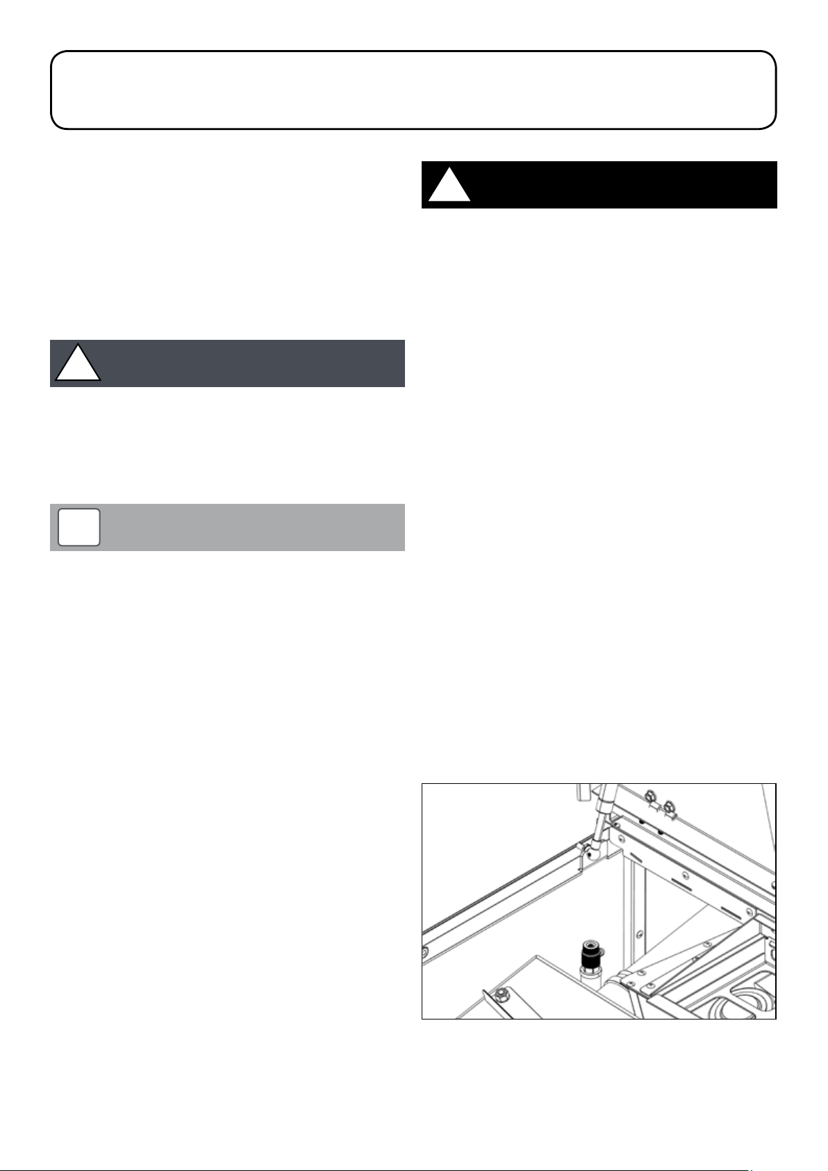
12 Servicing
12.1 General
It is essential that Grant Vecta boilers are serviced at regular inter vals
of no longer than 12 months OR when ‘Service’ is shown on the
burner control panel display – whichever comes FIRST.
The burner will automatically indicate ‘Service’ on the burner control
panel display once the pre-set period of pellet feed auger run time
(‘Hours Service’) is achieved. Refer to Section 9.6 for details on how
to access and check this setting in the boiler control parameter menu.
This interval is based on the auger running time, i.e. the actual
quantity of pellets used based on the pellet feed auger rate and pellet
delivery settings. Refer to Section 9.7 for details on how to access and
check this setting in the boiler control parameter menu.
!
The ash pan (located inside the combustion chamber) MUST
be periodically emptied by the user. This simple task must be
carried out when indicated by the Remote Grant Logo Indicator,
located within the house, flashing (fast flash).
Refer to Sections 1.5 and 1.6.
!
The amount of ash produced varies bet ween dif ferent pellet
brands and this will affect the frequency of cleaning and
maintenance required.
Servicing and replacement of parts must only be carried out by
a Grant Trained installer, or Grant Ser vice Engineer, who has
successfully completed the Grant Vecta wood pellet boiler training
course.
Details of every service should be entered in the Service log section
of the user guide.
A multi-purpose tool is supplied with the boiler for ser vicing and
cleaning. This is used for the following functions:
• As the door catch handle – required to open the combustion
chamber door
• As the ash pan carrying handle – required to remove the ash pan
from the boiler*
• To open the brazier catch
• To remove the brazier front plate
• To remove the brazier base plate
• To remove the brazier cotter pin
The multi-purpose tool is hung on a hook located on the panel to the
left of the combustion chamber door. Always replace the tool back on
this hook af ter use to ensure it is available when next required.
* An ash pan carrying handle is also supplied with the boiler. This
must be used in conjunction with the multi-purpose tool, to suppor t
the opposite end of the ash pan, when removing it from the boiler.
Refer to Section 12.6.5.
CAUTION
NOTE
12.2 Checks before Ser vicing
!
Before starting any work on the boiler, or on the pellet storage
and supply installation, please read the health and safety
information in Section 15.
BEFORE starting any service work on the boiler installation:
• Set the ON/STANDBY switch, on the boiler control panel, to
STANDBY. If the boiler was operating, wait for it to shut-down and
‘STANDBY’ is shown on the burner control panel display, before
proceeding fur ther.
• Isolate the electrical supply to the boiler and remove the fuse
from the fused spur.
WARNING
12.3 Heating System
Open the hinged hopper lid.
Undo the two screws (one on each side) and remove the access
cover from the top of the boiler. Refer to Figure 11-2.
Remove the top access cover from inside the top of the boiler.
Check the boiler for any indication of leaks from:
• Flow and return connections
• Manual air vent. Refer to Figure 12-1.
Remake any joints and re-check tightness of any fitting that may be
leaking.
If the boiler is part of a sealed heating system, check the following:
• System pressure
• Pressure relief valve operation
• Expansion vessel air charge pressure (when the system pressure
is zero)
Re-fill and vent the system to the required pressure. Refer to Section
6.
On either sealed or open-vented systems:
• Inspect and clean the in-line magnetic filter in accordance with
the filter manufacturer’s instructions.
• Ensure that adequate corrosion protection is present in system.
Figure 12-1: Location of manual air vent (water connection to wash
system removed for clarity)
Section 12: ServicingPage 54
Page 55

12.4 Flue System
12.4.1 Flue Terminal
!
Failure to maintain a clean flue can result in the emission of
flue gases into the dwelling or damage from potential fire in the
flue.
Check the flue terminal and ensure that it is not blocked or damaged.
12.4.2 Flue
To access the flue inspection hatch, remove the circular outer cover.
To do this, turn the knob in the centre of the outer cover approximately
one turn anticlockwise and pull the cover away from the inspection
pipe.
Remove the flue inspection hatch. Turn the knurled knob (in the centre
of the hatch) approximately one turn anticlockwise, pull the hatch out
of the flue and inspect the inside of the flue system.
Clean the flue by sweeping as required.
Replace the inspection hatch using the reverse procedure turning the
knurled knob approximately one turn clockwise to secure it in the flue.
Replace the circular outer cover using the reverse procedure, turning
the knob approximately one turn clockwise to secure the cover in
place.
12.4.3 Smoke Test
Following inspection and cleaning of the flue system, carry out
a smoke test as specified in The Building Regulations Approved
Document J, Appendix E, Section E15 – Smoke Test II.
WARNING
Figure 12-2: Wash system connection
• Unscrew and remove the five nuts (and washers) securing the
heat exchanger cover and remove it from the top of the heat
exchangers. Refer to Figures 12-3.
12.5 Combustion Ventilation
Check that the combustion air inlet to the boiler along the lower front
edge of the boiler front door is unobstructed. If necessar y remove any
obstructions, e.g. leaves, etc.
Check that the combustion air inlet to the burner, located in the font of
the boiler, is unobstructed.
12.6 Boiler
12.6.1 Overheat thermostat and Temperature probe
With the hinged hopper lid open and top access cover removed:
Check the following:
• That both the overheat thermostat probe and thermistor bulb are
fully inserted in the boiler waterway pocket (on the upper left side
of the boiler), and the retaining clip is fitted. Refer to Figure 11-3.
• The condition of thermistor cable and thermostat capillary, i.e.
not damaged, broken or kinked.
12.6.2 Primary heat exchanger
With the hinged hopper lid open and top access cover removed (as
Section 12.3 above):
• Shut off the cold water supply to wash system.
• Disconnect the water supply hose from the wash system. Refer
to Figure 12-2.
Figure 12-3: Heat exchanger cover
Clean primary heat exchanger as follows:
• Remove all eight mild steel spiral baf fles by lifting them vertically
up and out from the primary heat exchanger tubes. Refer to
Figure 12-4.
Figure 12-4: Primary heat exchanger spirals
• Clean down any ash inside tubes, using a suitable pipe brush,
into the combustion chamber and ash pan below.
• Carefully clean the Lambda sensor - located on the left side in
the top chamber of the primary heat exchanger. Remove any ash
deposits using a soft bristle brush (e.g. a small paint brush) and
Section 12: Servicing Page 55
Page 56

vacuum.
• Clean all ash deposits from top chamber of the primary heat
exchanger (above tubes) and shaker mechanism/plates, using
brush and vacuum.
• Clean and check condition of all spiral baffles.
• Re-fit baffles into heat exchanger tubes, fitting them through
shaker plates.
• Lift and drop each spiral baffle to check that all baffles are free
to move in their respective tubes.
12.6.3 Secondary Heat Exchanger
12.6.4 Fan
!
There are two dif ferent t ypes of spiral baffle fitted to the
secondary heat exchanger.
The spiral baffles fitted to the right hand side have a 2½ turn
spiral and are dif ferent to those on the lef t hand side which
have 4½ turn spiral.
Whenever these are removed, it is important that they are refitted in the correct side of the secondary heat exchanger.
With the hinged hopper lid open, top access cover and heat
exchanger removed (as per Section 12.6.2)
• Clean the secondary heat exchanger as follows:
• Remove all of the stainless steel spirals from the secondar y heat
exchanger tubes. Refer to Figure 12-5.
NOTE
Figure 12-6: - Location of fan
• With the hinged hopper lid open, top access cover and heat
exchanger cover removed (as per Section 12.6.2), clean the fan.
• Using a small wire brush, clean any ash deposits from the fan
blades and mounting plate.
!
When cleaning the fan blades ensure they are all thoroughly
cleaned. Uneven cleaning will result in the fan being ‘out of
balance’ and could cause damage to the fan motor.
Check and clean the wash system jets to ensure all ash deposits
•
and other debris is removed.
• Refit the heat exchanger cover to the top of the heat
exchanger(s) and secure with the nuts previously removed. Do
not over tighten.
• Reconnect air inlet hoses.
• Re-connect water supply hose to connection on wash system
manifold. Refer to Figure 12-2.
CAUTION
Figure 12-5: Secondary heat exchanger spirals
• Clean down any ash inside tubes, using a suitable pipe brush,
into the base of the condensing heat exchanger below.
• Clean all ash deposits from top chamber of secondary heat
exchanger (above tubes) using brush and vacuum.
• Clean and check condition of all spiral baffles. Replace if
necessary.
• Re-fit baffles into heat exchanger tubes, such that all the top
edges of the baffles are running ‘front to back’. Refer to Figure
11-9.
Figure 12-7: Removal of fan
Section 12: ServicingPage 56
Page 57
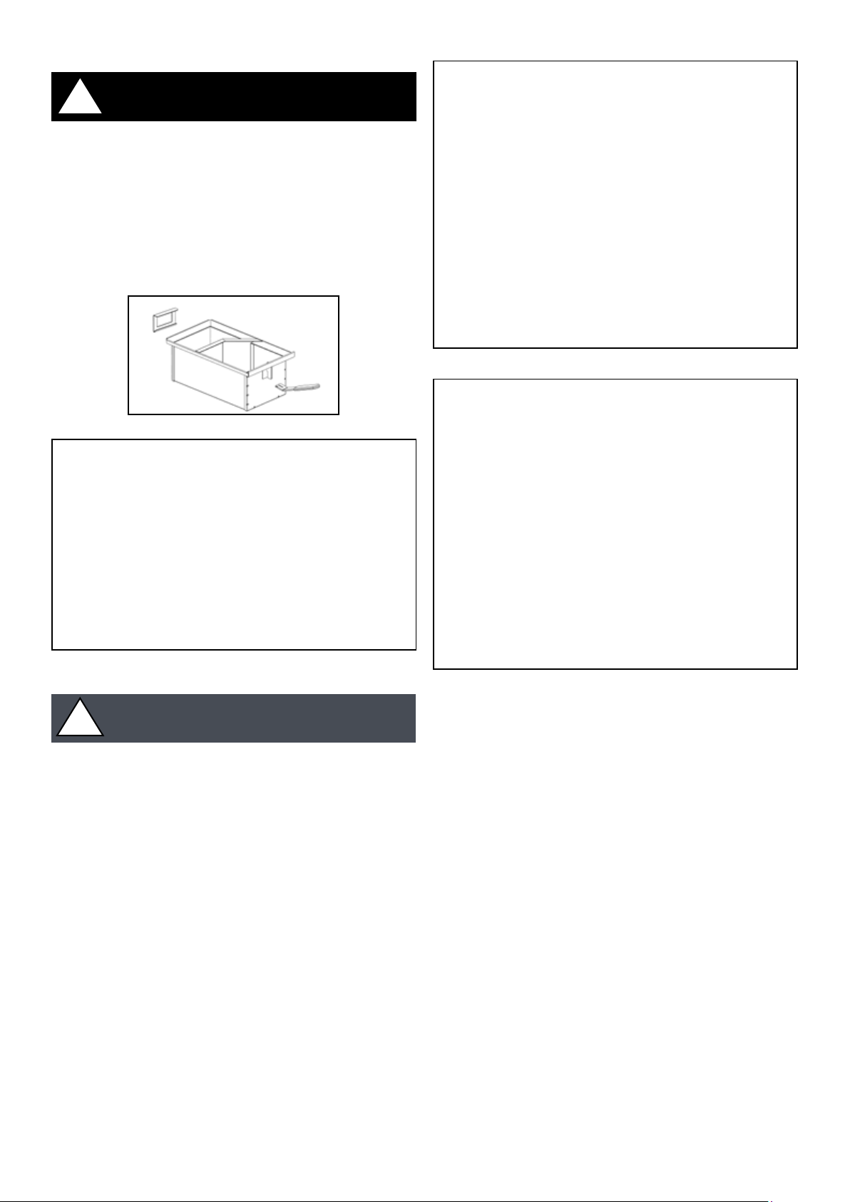
12.6.5 Combustion Chamber
!
Ensure the electrical supply to the boiler is isolated at the fused
spur before proceeding.
Shut off the isolator.
• Fit the multi-purpose tool (provided with the boiler) into slot in
door catch. Refer to Figure 11-5.
• Lift the tool handle to release the door catch and fully open the
combustion chamber door of the boiler. Refer to Figure 11-6.
• Using the multi-purpose tool supplied with the boiler, carefully
remove ash pan from combustion chamber. Refer to Figure 12-9.
WARNING
Figure 12-8: Carrying ash pan
Figure 12-10: Vertical combustion chamber baffle
Figure 12-9: Ash pan removal
!
Extreme care is required when emptying the ash pan as
smouldering ash could be present and cause serious damage
to persons or proper ty. Ensure the ash is disposed of in a safe
manner.
•
When carrying the ash pan use both the multi-purpose tool and
the ash pan carrying handle (also provided with the boiler). Refer
to Figure 12-8.
• Remove both the horizontal and vertical baffles from the rear
of the combustion chamber and inspect them. Refer to Figures
12-10 and 12-11.
• Clean off any remaining deposits using a brush and vacuum.
• Before re-fitting the baffles, remove all ash deposits from all the
internal combustion chamber surfaces using a vacuum.
• Clean any ash deposits from the inner face of the combustion
chamber door.
• Re-fit the baffles to the combustion chamber.
CAUTION
Figure 12-11: Horizontal combustion chamber baffle
Section 12: Servicing Page 57
Page 58

12.7 Burner
12.7.1 Dismantling the Burner
• Remove the flame pot from the top of the burner. Refer to Figure
12-15.
!
Ensure the electrical supply to the boiler is isolated at the fused
spur before proceeding.
To clean the burner thoroughly it is necessar y to dismantle it using the
following procedure:
• Fully open the combustion chamber door (as per Section 12.6.5).
• Clean any ash deposits from the external surfaces of the burner.
• Using the multi-purpose tool supplied with the boiler, rotate the
brazier catch (on the front of the burner) 90° anticlockwise to
release it from the upper front of the burner housing. Refer to
Figure 12-12.
WARNING
Figure 12-15: Removal of flame pot
• Using the multi-purpose tool supplied with the boiler, remove the
wire cotter pin that attaches the brazier assembly to the brazier
cleaning shaft. Refer to Figure 12-16.
Figure 12-12: Brazier catch
• Hinge down and remove the brazier front plate from the burner.
Refer to Figure 12-13.
Figure 12-13: Removal of brazier front plate
• Using the multi-purpose tool supplied with the boiler, remove
the brazier base plate from the lower front of the burner housing.
Refer to Figure 12-14.
Figure 12-16: Cotter pin removal
• Remove the brazier assembly from the burner. Pull to the right
(until it touches combustion chamber wall) and then remove it
from the front. Refer to Figures 12-17 and 12-18.
!
Do NOT attempt to force the brazier assembly open without
removing the wire cotter pin from the brazier cleaning shaft
Failure to follow this guidance will result in damage to cleaning
actuator, cleaning mechanism or brazier.
WARNING
Figure 12-14: Removal of brazier base plate
Section 12: ServicingPage 58
Page 59

Figure 12-17: Brazier assembly removal to side
!
The flange on one side of the octagonal pot is narrower than
the other seven sides. Refer to Figure 12-19. This side MUST
be located on the left hand side or the pot will not fit into the
burner housing.
Re-fit the brazier base plate into the lower front of the burner
•
housing using the multi-purpose tool supplied with the boiler
• Re-fit the brazier front plate onto the lower front of the burner
housing. Secure in place by engaging the brazier catch into the
catch plate on the upper front face of the burner housing. Rotate
catch 90° clockwise to ensure it is fully engaged in the catch
plate using the multi-purpose tool supplied with the boiler.
• Finally, remove any remaining deposits of ash from the bottom of
the combustion chamber and then re-fit the ash pan in the base
of the combustion chamber.
NOTE
Figure 12-18: Brazier assembly removal
12.7.2 Cleaning the Burner
Once dismantled, clean the burner as follows:
• Clean and inspect the burner housing (inside the combustion
chamber).
• Remove all ash deposits and check that all openings and air
holes are clear.
• Clean and inspect the brazier assembly, flame pot (refer to
Figure 12-19), brazier base plate and brazier front plate.
!
The boiler will perform an automatic brazier cleaning operation
when power to the boiler is re-connected.
12.7.3 Photocell
Remove the photocell from the mount on the left side of the heat
exchanger. Check and clean the photocell. Replace if damaged. Refer
to Figure 12-20.
NOTE
Figure 12-20: Photocell location
12.8 Ignition Element
Location flange
Figure 12-19: Flame pot flange
• Remove all ash and clinker deposits from these parts using a
wire brush and, where necessary, a flat scraper. Check that all air
holes are clear.
• Re-fit brazier assembly into the burner housing – locating the
brazier cleaning shaft into the opening in the left side of the
brazier assembly.
• Replace the wire cotter pin to secure the brazier assembly to the
brazier cleaning shaft.
• Re-fit the flame pot into the top of the burner housing.
Remove and check the condition of the ignition heater element.
To remove; first remove steel clip holding grommet in place. Grasp the
black grommet and pull the element from the mounting tube (on the
left side of the heat exchanger). Do NOT pull on the element power
cable. Refer to Figure 12-21.
Figure 12-21: Ignition element location
Section 12: Servicing Page 59
Page 60
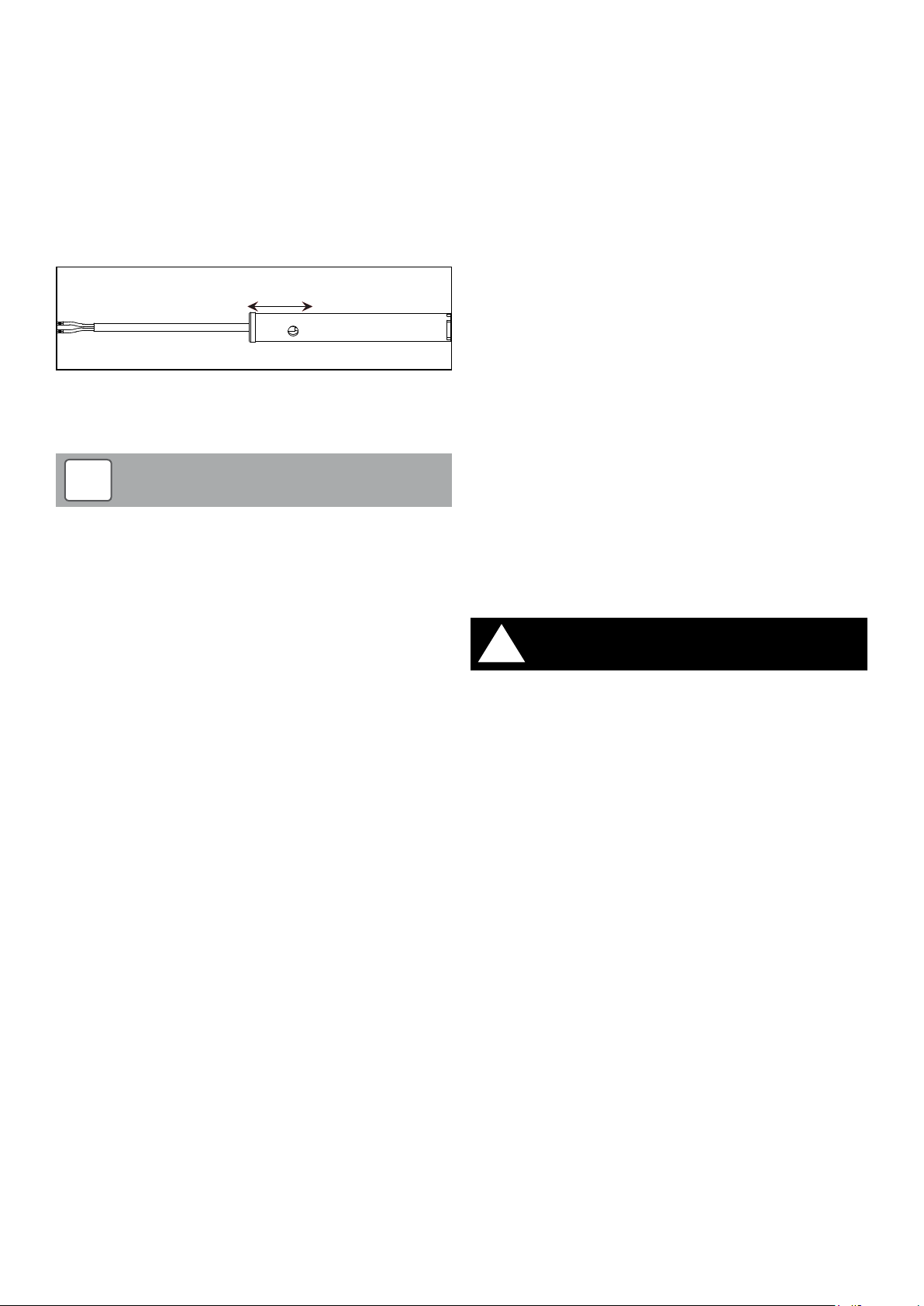
Clean the inside of the element mounting tube using a suitable size of
35 - 40mm
tube brush.
Check and clean both ignition element and ceramic socket and
ensure the ignition element if correctly fitted into the ceramic socket.
To ensure that the element is correctly positioned in the tube check
the distance from the shoulder of the grommet to the element socket
is 35 – 40mm. Adjust the position of the grommet as necessary. Refer
to Figure 12-22.
Refit ignition element into mounting tube until grommet is fully pushed
home.
Refit steel clip to secure grommet in place.
Figure 12-22: Correct ignition element position
12.9 Condensate Disposal System
12.9.1 Condensate Trap
!
The condensate trap, condensate outlet and disposal
pipe MUST be checked on EVERY service and cleaned as
necessary. Failure to regularly check and clean the condensate
trap and disposal pipe may result in damage to the boiler and
this will not be covered by the product guarantee.
The condensate must be checked and cleaned as necessary on
every service.
To check/clean the trap:
• Disconnect the condensate disposal system from the outlet of
the trap.
• Disconnect the trap from the boiler condensate outlet. Refer to
Section 5.5 for condensate trap connection details.
• Check that the boiler condensate outlet is clear. Remove any
blockage or ash build-up.
• Thoroughly clean out the trap to remove any deposits and re-fit
to condensate disposal pipe.
• Reconnect trap to the boiler condensate outlet. Refer to Section
5.5 for condensate trap connection details.
NOTE
12.10 Boiler Settings
With the electrical power to the hopper and boiler switched on, and
the boiler ON/STANDBY switch set to STANDBY, check that ALL boiler
settings in the ‘parameter menu’ match those set on commissioning
(i.e. as recorded on the Commissioning Report form), a copy of which
was left with the householder/user.
Refer to Sections 9.6 and 9.7 for details on how to access and check
these settings.
Reset the ‘Service’ period to zero as follows:
• Access the ‘Service Menu’ (refer to Section 9.6 for guidance)
• When in the ‘Service Menu’ - press button 2 to scroll down to
‘Reset Service Timers’ function
• Press button 4 to select ‘Reset Service Timers’ function
• Press button 4 to confirm
• Press button 3 twice to return to ‘Home Screen’
12.11 Hopper Lid Cut-out Switch
Check operation of the cut-out switch. Follow the procedure given in
Section 11.4.
12.12 Combustion Checks
To ensure safe and ef ficient operation of the boiler, it is essential that
the boiler combustion is re-checked and adjusted as necessary.
12.12.1 Combustion Chamber Draught
Check the combustion chamber draught. Follow the procedure given
in Section 11.8.
11.12.2 Flue Gas Analysis
Check the %CO
Section 11.9.
!
To ensure safe and ef ficient operation of the boiler it is
important that boiler/burner is re-commissioning as detailed in
Section 11.
in the flue gases. Follow the procedure given in
2
WARNING
12.9.2 Condensate Disposal Pipe
Before re-connecting discharge pipe to the trap outlet:
• Check entire length of disposal pipe, for any leaks or blockages.
• Thoroughly clean to remove any deposits or replace as neces-
sary.
• Dismantle and Check that any outlets to a gully or hopper are not
obstructed. Remove any blockages.
12.9.3 Condensate Pump
If a condensate pump is fitted to the system, check:
• The condition of the holding tank. Thoroughly clean, if required,
to remove any deposits.
• Operation of the overflow cut-out float switch.
• That the pump is operating correctly.
Section 12: ServicingPage 60
Page 61
13 Fault Finding
13.1 Fault Codes
The boiler control system monitors all aspects of the boiler operation
and, should a fault occur, will display a fault message and fault code
on the control panel LCD.
The fault messages and codes are as follows:
Fault message Err or code
Safety Relay Fault 1
Auger Monitor Fault 2
Failed Pellet Lighting 2
Ignition Monitor Fault 3
Safety Charge Pipe Stat 3
Overheat Thermostat 4
Servo Motor Blocked 8
Flue Fan Ignition Rate 10
Flue Fan Failed 11
Water Flow Switch 12
Fuel Low 13
Safety Shutdown 14
Door Open 15
Hopper Lid Open 16
Burner Fan Ignition Rate 17
Burner Fan Failed 18
False Flame 19
EN60730 Fault (PCB fault) 20
Safety Flap Open 21
Safety Flap Closed 22
APS Fault 23
Safety Monitor 24
Section 13: Fault Finding Page 61
Page 62

13.2 Fault Details
13.2.1 Failed Pellet Lighting
Section 13: Fault FindingPage 62
Page 63

13.2.2 Overheat Thermostat
Section 13: Fault Finding Page 63
Page 64

14 Spare Parts
14.1 Boiler Parts List
Item Description Grant UK product code Quantity
N/A Front door lock and keys VEC001 1
N/A Lid safety switch WPS88 1
N/A Front cleaning door safety switch WPS88 1
N/A Electrical isolation switch VEC002 1
N/A Display board (LED screen) VEC003 1
N/A On / of f switch VEC004 1
N/A Vecta PCB board VEC005 1
N/A Power unit for PCB board VEC006 1
N/A Lambda sensor VEC007 1
N/A Lambda sensor PCB board VEC008 1
N/A Complete heat exchanger cover complete with manifold VEC009 1
N/A Nozzle tube (for wash down) VEC010 1
N/A Nozzle holder (for wash down) VEC011 1
N/A Wash down flexible hose Special - please call Grant UK 1
N/A Primary heat exchanger spirals VEC012 8
N/A Secondary heat exchanger spirals (LHS - 4½ turns) VEC013 15
N/A Secondary heat exchanger spirals (RHS - 2½ turns) VEC014 15
N/A Shaker box gasket VEC015 1
N/A Photocell WPS09 1
N/A Photocell tube VEC016 1
N/A Ignition element WPS10A 1
N/A Ignition element tube VEC017 1
N/A Ash pan VEC018 1
N/A Carry handle Special - please call Grant UK 1
N/A Multi purpose tool VEC019 1
N/A Vertical combustion chamber baf fle VEC020 1
N/A Horizontal combustion chamber baffle VEC021 1
N/A Brazier front plate c/w catch VEC022 1
N/A Brazier base plate VEC023 1
N/A Complete brazier assembly VEC024 1
N/A Flame pot VEC025 1
N/A Air pressure switch VEC026 1
N/A Manual air vent VEC027 1
N/A High limit stat WPS107 1
N/A Temperature thermistor WPS25 1
N/A Solenoid coil and valve WPS76 1
N/A Flue fan motor VEC028 1
N/A Actuator board VEC029 1
N/A Fire damper motor (Belimo) VEC030 1
N/A Auger motor (SPG) Special - please call Grant UK 1
N/A Low fuel warning microswitch Special - please call Grant UK 1
N/A Low fuel diaphragm Special - please call Grant UK 1
N/A Linear motor (Lynex) VEC031 1
N/A Fuse (5 amp - fast acting glass) Special - please call Grant UK 1
Section 14: Spare Par tsPage 64
Page 65

14.2 Side Store Par ts List
Item Description Grant UK product code Quantity
N/A Auger motor (SPG) Special - please call Grant UK 1
N/A Low fuel warning microswitch Special - please call Grant UK 1
N/A Low fuel diaphragm Special - please call Grant UK 1
Section 14: Spare Par ts Page 65
Page 66

15 The Clean Air Act 1993 and
Smoke Control Areas
The Clean Air Act 1993 and Smoke Control Areas
Under the Clean Air Act local authorities may declare the whole or
part of the district of the authority to be a smoke control area. It is an
offence to emit smoke from a chimney of a building, from a furnace
or from any fixed boiler if located in a designated smoke control area.
It is also an offence to acquire an “unauthorised fuel” for use within
a smoke control area unless it is used in an “exempt” appliance
(“exempted” from the controls which generally apply in the smoke
control area).
The Secretary of State for Environment, Food and Rural Affairs
has powers under the Act to authorise smokeless fuels or exempt
appliances for use in smoke control areas in England. In Scotland and
Wales this power rests with Ministers in the devolved administrations
for those countries. Separate legislation, the Clean Air (Northern
Ireland) Order 1981, applies in Northern Ireland. Therefore it is a
requirement that fuels burnt or obtained for use in smoke control
areas have been “authorised” in Regulations and that appliances
used to burn solid fuel in those areas (other than “authorised” fuels)
have been exempted by an Order made and signed by the Secretar y
of State or Minister in the devolved administrations.
Further information on the requirements of the Clean Air Act can be
found at www.gov.uk/smoke-control-area-rules
Your local authority is responsible for implementing the Clean Air Act
1993 including designation and supervision of smoke control areas
and you can contact them for details of Clean Air Act requirements.
The Grant Vecta 4-16 Condensing Wood Pellet Boiler has been
recommended as suitable for use in smoke control areas when
burning EN Plus A1 pellets.
Section 15: The Clean Air Act and Smoke Control AreasPage 66
Page 67

16 Declaration of Conformity
EC Declaration of Conformity
In accordance with BS EN ISO/IEC 17050-1:2004
Grant Engineering (UK) Limited
We:
Hopton House
Of:
Hopton Industrial Estate
Devizes
SN10 2EU
Telephone:
Fax:
Email:
Website:
Declare that:
Equipment:
Model Name/Number:
In accordance with the following Directives:
2006/95/EC Conforms with the safety objectives of the Low Voltage Directive and its amending directives.
2004/108/EC Conforms with the essential protection requirements of the Electromagnetic Compatibility Directive and
its amending directives.
92/42/EC Conforms with the requirements of the Boiler Efficiency Directive.
+44 (0)1380 736920
+44 (0)1380 736991
www.grantuk.com
Floor Standing Domestic Condensing Wood Pellet Boiler
Grant Vecta 4-16 Wood Pellet Boiler
Has been designed and manufactured to the following specifications:
EN60335-1:2012 Household and similar electrical appliances. Safety – General requirements.
EN60335-2-102:2006+A1:2010 Household and similar electrical appliances. Safet y. Particular requirements for gas, oil and sold fuel
burning appliances having electrical connections.
EN303-5:2012 Heating Boilers for solid fuels. Manually or automatically stoked. Nominal heat output up to 500kW.
I hereby declare that the equipment named above has been tested and found to comply with the relevant sections of the above referenced
specifications. The unit complies with all essential requirements of the Directives.
Responsible Person:
Position: Technical Manager
Signature:
Date: 15th December 2016
Neil Sawers
11
Section 16: Declaration of Conformity Page 67
Page 68

17 Health and Safety Information
Under the Consumer Protection Act 1987 and Section 6 of the Health
and safety at Work Act 1974, we are required to provide information
on substances hazardous to health (COSHH Regulations 1988).
Adhesives, sealants and paints used in the manufacture of the
product are cured and present no known hazards when used in the
manner for which they are intended.
The following other materials are present in the product:
17.1 Insulation Materials
Material types:
Ceramic fibre board, mineral wool.
Description:
Rigid board, slabs, sleeves, gaskets, ropes.
Known Hazards:
May cause temporary irritation or rash to skin. High dust levels may
irritate eyes and upper respiratory system.
Precautions:
Avoid unnecessary or rough handling, or harsh abrasion of boards.
Normal handling and use of material should not produce high dust
levels.
Avoid inhalation and contact with skin and eyes.
After handling always follow normal good hygiene practices.
17.2 Sealant and Adhesive
Material Types:
Silicone elastomer.
Description:
Sealant and adhesive.
Known Hazards:
Irritation to eyes.
Precautions:
Avoid inhalation of vapour, contact with eyes and prolonged or
repeated contact with skin.
After handling always follow normal good hygiene practices.
Protection:
Use eye protection. Rubber or plastic gloves should be worn where
repeated contact occurs and a face mask worn when working in
confined spaces.
First Aid:
Eyes – flush eyes with water for 15 minutes. Seek immediate medical
attention.
Protection:
Use disposable gloves, face mask and eye protection.
First Aid:
Eyes – if irritation occurs, wash eyes with copious amounts of water. If
symptoms persist, seek immediate medical advice.
Skin:
If irritation occurs, wash under running water before washing with
soap and water.
Inhalation:
Remove to fresh air, drink water to clear throat and blow nose to
remove dust/fibres.
Ingestion:
Drink plenty of water.
Skin:
Wipe off and wash with soap and water.
Inhalation:
Remove to fresh air.
Section 17: Health and Safety InformationPage 68
Page 69
18 Disposal and Recycling
General
Grant wood pellet boilers incorporate components manufactured from a variet y of different materials. The majorit y of these materials can be
recycled whilst the smaller remainder cannot.
Materials that cannot be recycled must be disposed of according to local regulations using appropriate waste collection and/or disposal services.
Disassembly
There is little risk to those involved in the disassembly of this product. Please refer to and follow the Health and Safety Information given in the
Installation & Servicing Instructions provided with the boiler.
For guidance on the disassembly of the boiler refer to the information given in the Servicing section of the Installation & Ser vicing Instructions
provided with the boiler.
Recycling
Many of the materials used in Grant oil boilers can be recycled, these are listed in the table below:
Component Material
Outer casing panels Mild steel (polyester powder coated)
Primary heat exchanger and baffles Mild steel
Secondary heat exchanger Stainless steel
Secondary heat exchanger spirals Stainless steel
Pipework Copper
Burner body/brazier Stainless steel
Electrical wiring Copper / plastic
Thermostats Copper / plastic
Printed circuit boards Copper / plastic
Disposal
All materials other than those listed above must be disposed of responsibly as general waste
Section 18: Disposal and Recycling Page 69
Page 70

19 Guarantee
You are now the proud owner of a wood pellet boiler from Grant
Engineering (UK) Limited, which has been designed to give years of
reliable, trouble free, operation.
Grant Engineering (UK) Limited guarantees the manufacture of the
boiler including all electrical and mechanical components for a period
of twelve months from the date of installation
4
, provided that the
boiler has been installed in full accordance with the installation and
servicing instructions issued.
This will be extended to a total period of two years if the boiler is
registered with Grant Engineering (UK) Limited within thir ty days of
installation
4
and it is serviced at regular intervals
3
. See main Terms
and Conditions below.
Registering the product with Grant Engineering (UK) Limited
Please register your wood pellet boiler with Grant Engineering UK
Limited within thirty days of installation
grantuk.com, where you can register your boiler for a further
4
. To do so visit w ww.
twelve
months guarantee (giving t wo years from the date of installation).
This does not affect your statutory rights
If a fault or defect occurs within the manufacturer’s guarantee
period
If your boiler should fail within the guarantee period, you must
contact Grant Engineering (UK) Limited who will arrange for the
repair under the terms of the guarantee, providing that the boiler has
been correctly installed, commissioned and regularly ser viced by a
competent person and the fault is not due to tampering, running out
of fuel, the use of unapproved wood pellets, contamination, debris,
system water contamination, misuse, trapped air or the failure of any
external components not supplied by Grant Engineering (UK) Limited,
e.g. motorised valve, etc.
This two year guarantee only applies if the boiler is registered
with Grant Engineering (UK) Limited within thir ty days of
installation
4
and is regularly ser viced3.
In the first instance
Contact your installer or commissioning engineer to ensure that
the fault does not lie with the system components or any incorrect
setting of the system controls that falls outside of the manufacturer’s
guarantee other wise a service charge could result. Grant Engineering
(UK) Limited will not be liable for any charges arising from this
process.
If a fault covered by the manufacturer’s guarantee is found
Ask your installer to contact Grant Engineering (UK) Limited Ser vice
Department on +44 (0)1380 736920 who will arrange for a competent
service engineer to rectify the fault.
1
.
Remember - before you contact Grant Engineering (UK)
Limited:
• Ensure the boiler has been installed, commissioned and ser viced
by a competent person in accordance with the installation and
servicing instructions.
• Ensure there is an adequate quantity of the approved type of
pellets in the hopper (and bulk store if fitted) to supply the burner.
• Ensure the problem is not being caused by the heating system
or its controls. Consult the installation and servicing instructions
supplied with the boiler for guidance.
• Ensure the problem is not being caused by poor qualit y or
incorrect pellets.
Free of charge repairs
During the two year guarantee period no charge for parts or
labour will be made provided that the boiler has been installed and
commissioned correctly in accordance with the manufacturer’s
installation and servicing instructions, it was registered with Grant
Engineering (UK) Limited within thir ty days of installation
of regular servicing is available
3
.
4
and details
The following documents must be made available to Grant
Engineering (UK) Limited on request:
• Proof of purchase
• Commissioning Report Form
• Service documents
Chargeable repairs
A charge may be made (if necessary following testing of parts) if the
cause of the breakdown is due to any fault(s) caused by the plumbing
or heating system, e.g. contamination of parts due to system
contamination, sludge, scale, debris or trapped air. See ‘Extent of
manufacturer’s guarantee’ below.
Extent of manufacturer’s guarantee:
The manufacturer’s guarantee does not cover the following:
• If the boiler has been installed over t wo years.
• If the boiler has not been installed, commissioned, or ser viced
by a competent person in accordance with the installation and
servicing instructions.
• The serial number has been removed or made illegible.
• Fault(s) due to accidental damage, tampering, unauthorised
adjustment, neglect, misuse or operating the boiler contrary to
the manufacturer’s installation and servicing instructions.
• Damage due to external causes such as bad weather conditions
(flood, storms, lightning, frost, snow, ice), fire, explosion,
accident or theft.
• Fault(s) due to incorrectly sized expansion vessel(s), incorrect
vessel charge pressure or inadequate expansion on the system.
• Fault(s) caused by external electrics and ex ternal components
not supplied by Grant Engineering (UK) Limited.
• Problems caused by lack of pellets, the use of unapproved
pellets or faults with the pellet storage and supply system (if not
supplied by Grant Engineering (UK) Limited).
• Removing any pellet store or hopper contamination or blockages
in the pellet augers, pellet hopper or bulk pellet store.
• Removal of dust from the pellet augers, pellet hopper or bulk
pellet store.
• Problems due to the flue system being incorrectly fitted or not
installed to meet installation requirements.
Section 19: GuaranteePage 70
Page 71

• Boiler servicing, de-scaling or flushing.
• Cleaning out condensate traps/discharge pipework or thawing
frozen condensate pipework.
• Checking or replenishing system pressure.
• Electrical cables and plugs, heating system controls not supplied
by Grant Engineering (UK) Limited.
• Heating system components, such as radiators, pipes, fittings,
pumps and valves not supplied by Grant Engineering (UK)
Limited.
• Instances where the wood pellet boiler has been un-installed and
re-installed in another location.
• Use of spare parts not authorised by Grant Engineering (UK)
Limited.
• Consumable items including, but not limited to, gaskets, seals,
etc.
IMPORTANT
Do not wait until your wood pellet supply runs out before you re-order.
Dust in the bottom of the pellet store or hopper may prevent the
supply of pellets to the burner. It is impor tant that this is checked for
and, if dust is present, removed on the regular service to prevent
nuisance stoppage of the boiler.
Terms of manufacturer’s guarantee:
• The Company shall mean Grant Engineering (UK) Limited.
• The boiler must be installed by a competent installer and in full
accordance with the relevant Codes of Practice, Regulations and
Legislation in force at the time of installation.
• The boiler is guaranteed for t wo years from the date of
4
installation
completed
, providing that regular servicing has been
3
and the boiler registered with the Company within
thirty days of installation. Any work undertaken must be
authorised by the Company and carried out by a competent
service engineer.
• The boiler must be installed by an engineer that has attended
and passed a Grant Engineering (UK) Limited accredited training
course.
• The shell (heat exchanger) of the wood pellet boiler is covered by
a five year parts only guarantee from the date of installation
4
.
This is subject to the following:
• The boiler is operated correctly, in accordance with the
installation and servicing instructions.
• Proof is provided that the system has been flushed or
chemically cleaned where appropriate (refer to BS 7593)
and that the required quantity of a suitable corrosion
inhibitor added.
• Proof of regular ser vicing (including the checking of any
expansion vessels and pressure relief valves) must be
provided if and when requested by the Company.
IMPORTANT
Grant Engineering (UK) Limited strongly recommends that
a Grant Mag-One in-line magnetic filter/s (or equivalent
5
)
is fitted in the heating system pipework. This should be
installed and regularly ser viced in accordance with the
filter manufacturer’s instructions.
• This guarantee does not cover breakdowns caused by incorrect
installation, neglect, misuse, accident or failure to operate the
boiler in accordance with the manufacturer’s installation and
servicing instructions.
• The boiler is registered with the Company within thirty days
of installation
rights
4
. Failure to do so does not affect your statutory
1
.
• The balance of the guarantee is transferable providing the
installation is serviced prior to the dwelling’s new owners taking
up residence. Grant Engineering (UK) Limited must be informed
of the new owner’s details.
• The Company will endeavour to provide prompt service in
the unlikely event of a problem occurring, but cannot be held
responsible for any consequences of delay however caused.
• This guarantee applies to Grant Engineering (UK) Limited
boilers purchased and installed on the UK mainland, Isle of
Wight, Channel Islands and Scottish Isles only
2
. Provision of inguarantee cover elsewhere in the UK is subject to agreement
with the Company.
• All claims under this guarantee must be made to the Company
prior to any work being undertaken. Invoices for call out/repair
work by any third party will not be accepted unless previously
authorised by the Company.
• Proof of purchase and date of installation, commissioning and
service documents must be provided on request.
• If a replacement boiler is supplied under the guarantee (due to
a manufacturing fault) the product guarantee continues from the
installation date of the original boiler, and not from the installation
date of the replacement
4
.
• Breakdown/failure due to lime scale will not be covered by this
guarantee.
• The replacement of a boiler under this guarantee does not
include any consequential costs.
• The boiler must not be sited in a location where it may be
subjected to frost.
• The ceramic ignition element is covered by a two year guarantee.
Hard water advice
If you live in a hard water area, protection against scaling of the wash
system manifold in your boiler must be provided.
You should fit an appropriate scale inhibitor or water softener as
any breakdown caused by water scaling is not covered by either the
manufacturer’s guarantee. Ask your installer for advice.
Foot notes:
1. Your statutory rights entitle you to a one year guarantee period
only.
2. The UK mainland consists of England, Scotland and Wales only.
Please note that for the purposes of this definition, Northern
Ireland, Isle of Man and Scilly Isles are not considered part of the
UK mainland.
3. Your wood pellet boiler must be regularly serviced as per the
installation and servicing instructions, (even when the guarantee
has expired) to prolong the lifespan and ensure it is operating
safely and efficiently.
4. The guarantee period will commence from the date of
installation, unless the installation date is more than six months
from the date of purchase, in which case the guarantee period
will commence six months from the date of purchase.
5. As measured by gauss. The Mag-One magnetic filter has a
gauss measurement of 12000.
Version 1.0 - December 2014
Section 19: Guarantee Page 71
Page 72

Grant EnGinEErinG (UK) LimitEd
Hopton House, Hopton Industrial Estate, Devizes, Wiltshire, SN10 2EU
Tel: +44 (0)1380 736920 Fax: +44 (0)1380 736991
Email: [email protected] www.grantuk.com
 Loading...