

Page 1

EPKIT
Fitting and User Instructions
for Electronic Programmer
Suitable for
Vortex Pro Kitchen/Utility and
Vortex Pro Internal Combi e models
IMPORTANT
These fitting Instructions must be read in conjunction with the
wiring diagrams given in the Installation manual supplied with the boiler
Part No. DOC19 REV04 May 2011
FITTING INSTRUCTIONS
1. Kit contents
The Electronic Programmer Kit (Ref. EPKIT) for
Grant Vortex Pro Kitchen/Utility and Vortex Pro
Internal Combi e boilers contains the following
items:
1 x Grasslin 'Tactic' 7-day two channel
electronic programmer
1 x Wiring harness – 5 x 400mm wires (Red,
Yellow, Orange, Brown and Blue)
1 x Fitting and User instructions
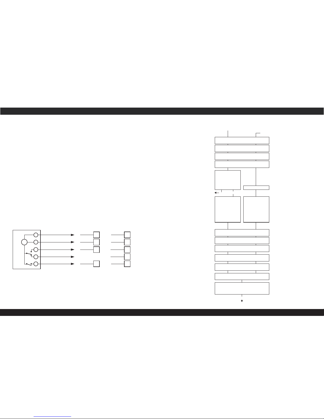
2. Electrical connections
The wiring harness must be connected to the
electronic programmer as follows:
Blue wire: To Mains Neutral terminal 2 on
the programmer
Brown wire: To Mains Line terminal 1 on the
programmer
Orange wire: To Hot water On terminal 3 on
the programmer
Yellow wire: To Hot water Off terminal 4 on
the programmer (see Section 4)
Red wire: To Heating On terminal 5 on the
programmer
3. Fitting the programmer
Important: Ensure the electrical supply to the
boiler has been isolated before fitting the
programmer
Vortex Pro Kitchen/Utility – System &
Non-system Models
1. Remove front and top boiler casing panels.
Remove the four screws and lift off top cover
from control panel.
2. Remove Brown wire link from terminals
1 & 4 on the boiler terminal block.
3. Carefully push through the square pre-cut
'knockout' section on the control panel front.
4. Connect five wires provided to the terminals
of the electronic programmer – refer to
Section 2 above.
5. Feed the wires through hole in control panel
front and then up and to the left of the
terminal block platform. Connect wires to
terminals on control panel – refer to
connection diagram in Section 4.
6. Locate the electronic programmer in the
square hole in control panel front – with the
terminals pointing to the right. Secure by
turning the two screws (in upper right and
lower left corners) a quarter turn clockwise.
7. Re-fit top cover to control panel and fasten
with the four screws.
USER INSTRUCTIONS
General notes on using the programmer
The programmer automatically controls the
times at which your boiler operates to provide
heating and hot water. It also provides a
permanent display of the time of day (24 hr or
am/pm display) and day of the week. Indicators
on the display show when both the hot water
(indicated by a tap symbol) and heating
(indicated by a radiator symbol) is either ON or
OFF.
If the electricity supply to the boiler is
interrupted, e.g. during a power cut, the display
will remain and the programmer will retain the
time and on/off program settings. It will not
have to be reset when the supply is restored.
The programmer is supplied with three pre-set
program options each giving different On/Off
settings. Refer to page 3 – To select and use a
pre-set program. Please note that these preset programs will switch both heating and hot
water ON and OFF at the same times.
Alternatively, you can set your own program of
On/Off settings, with different ON and OFF
times for heating and Hot water as you require.
Different On/Off settings for different days of the
week can also be set. You can set up to 10 ON
and 10 OFF commands throughout the week.
Refer to page 5 – Setting your own program.
Once set this program can be changed at any
time as required.
When setting the times for the ON periods it is
useful to remember that it might take up to an
18
This manual is accurate at the date of printing but will be superseded and should be disregarded if specifications and/or appearances are
changed in the interests of continued product improvement.
All goods sold are subject to our official Conditions of Sale, a copy of which may be obtained on application.
© Grant Engineering (UK) Limited 2011. No part of this manual may be reproduced by any means without prior written consent.
Grant Engineering (UK) Limited
Hopton House, Hopton Industrial Estate, Devizes, Wiltshire SN10 2EU
Telephone: (01380) 736920 Fax: (01380) 736991
email: info@grantuk.com website: www.grantuk.com
hour for the house to become warm, especially
in colder weather. Also the effect of the central
heating will remain for a time when the central
heating is turned off.
A hot water cylinder may take ½ hour or more
to heat up fully. A well insulated cylinder will
retain its heat for quite some time after the
boiler is turned off.
When setting the time for the start of the first
ON period it must be after midnight. The time
for the end of the last ON period can be after
midnight. Refer page 6 - for the 'Shift' function
section.
While setting any times, if a period of more than
1 minute elapses since the last key was
pressed, the programmer automatically reverts
back to the original program. Any changes
made up to that point will be lost as they were
not confirmed.
To temporarily override the current switching
time, i.e. change OFF to ON or ON to OFF, use
the ‘+’ and ‘-’ keys on the programmer.
Pressing the ‘+’ key will advance the Heating to
the next program operation and the ‘-’ key will
do the same for the Hot Water.
NB. The programmer will NOT automatically
return to the set program at the start of the
next program operation. Refer to Page 6 - To
manually override automatic operation.
For ‘Summer’ use the central heating can be
set to OFF by pressing the ‘+’ key. Check that
the ‘switching status’ display indicates that
the heating function is OFF.
Page 2
Vortex Pro Combi – Internal Models
1. Remove front and top boiler casing panels.
Loosen (do not remove) the four screws
securing control panel to the side panels.
Hinge the panel forward to access top and
rear of control panel.
2. Remove the two screws and lift off the
terminal block cover from top of control
panel.
3. Remove both the Red and Black wire links
from terminals 17 & 18 and 19 & 20 on
control panel.
4. Carefully push through and remove square
pre-cut 'knockout' section in the control
panel front.
5. Connect four wires provided to terminals of
the electronic programmer – refer to Section
2 above.
Note that the Yellow wire supplied in the kit
must not be used.
4. Connection diagram
6. Feed the wires through hole in control panel
front and then up through rectangular
opening in control panel top. Connect wires
to terminals on control panel – refer to
Connection diagram.
7. Locate the electronic programmer in the
square hole in control panel front – with the
terminals pointing to the right. Secure by
turning the two screws (in upper right and
lower left corners) a quarter turn clockwise.
8. Re-fit terminal block cover on control box
and fasten with the two screws.
Refer to the instructions on the following pages
for operating and setting the programmer.
IMPORTANT: After fitting the programmer
leave these instructions with the User.
2
1
3
4
5
M
Electronic
programmer
N - Blue
L - Brown
HW On - Orange
HW Off - Yellow
CH On - Red
21
Blue
Brown
Orange
Red
22
17
19
2
Blue
Brown
Orange
Red
1
7
Yellow
6
5
Vortex Pro Boilers - Wiring terminals
Pro Combi e
(internal models)
Pro Kitchen/Utility
(system & non-system)
NOTE: When using the EP kit with an ‘S-plan’ type control system (using
2 x 2 - port zone valves) the YELLOW wire is not required and should not be used.
IMPORTANT - For Vortex Pro Combi e boilers the YELLOW wire must not be used.
Programming sequence diagram
Reset (first installation adjustment) Review/adjust
Menu
Set time: Hour
Hour blinking, using to select, then OK +/- to confirm
Set time: Format 24h or am/pm
24h blinking, using +/- to select, then OK to confirm
Set time: Minute
Minute blinking, using to select, then OK +/- to confirm
Set time: Day
Monday (1) blinking, using to select, then OK +/- to confirm
Set Program: P01/ P02/ P03
or P--
Using +/- to select, then OK
To set ON/OFF times
Or
Press Menu to terminate
programming
Note:
P01-P03
are pre-set
P01is pre-set
Set Program: P01/ P02/ P03
or P– –
Setting switching times:
First free memory location
blinks
Press ‘-’ to go back one
memory location
Press OK for setting the
switching times.
Menu OK
Prog01
Setting switching times:
First free memory location
blinks
Press OK for setting the
switching times.
Set switching ON time:Hour
Hour blinking, using to select, then OK +/- to confirm
Set switching ON time:Minute
Minutes blinking, using to select, then OK +/- to confirm
Set switching ON time:Days
Mon Su (1 7) blinking, using to select, then OK +/- to confirm
Set display: channel 1 or 2
Ch1 blinking, using to select, then OK +/- to confirm
Set switching OFF time:Hour
Hour blinking, using to select, then OK +/- to confirm
Set switching OFF time:Mnute
Minute blinking, using to select, then OK/Menu +/- to confirm
A maximum of 20 memory locations
can be occupied:
10 switching ON times
10 switching OFF times
Menu
Run
72
(see note)
Page 3

1
2
3
4
5
6
7
14
16
18
20
22
24
Res. Menu OK
1h
0 2 4 6 8 10 12
Res. Menu OK
1h
1.4 Set minutes
1
2
3
4
5
6
7
14
16
18
20
22
24
0 2 4 6 8 10 12
1 1 2
1 = Monday
2 = Tuesday
3 = Wednesday
4 = Thursday
1.5 Set week day
5 = Friday
6 = Saturday
7 = Sunday
1
2
3
4
5
6
7
14
16
18
20
22
24
0 2 4 6 8 10 12
1.6 Select one of the pre-set programs
Use the following sequence after setting the time,
week day etc.
* If you wish to modify a pre-set program
do NOT press Menu after selecting the program
– but go to 1.7 To modify pre-set programs
next.
Setting your own program
Follow this sequence after setting the time,
week day, etc. as shown in steps 1.1 to 1.5 then
press ‘+’ three times until ‘P ’ shows on the
--
display. Then press OK.
1
2
3
4
5
6
7
14
16
18
20
22
24
0 2 4 6 8 10 12
prog
Res. Menu OK
1h
Press OK to confirm setting
1
2.1 Select first program ON time (prog 01)
1
2
3
4
5
6
7
prog
14
16
18
20
22
24
0 2 4 6 8 10 12
Res. Menu OK
1h
2.2 Set hour ON
1 1 2
1
2
3
4
5
6
7
prog
14
16
18
20
22
24
0 2 4 6 8 10 12
2.3 Set minutes ON
Res. Menu OK
1h
1 1 2
2.4 Set week day ON
1
2
3
4
5
6
7
prog
14
16
18
20
22
24
0 2 4 6 8 10 12
Res. Menu OK
1h
1 1 2
1
2
3
4
5
6
7
Possible week blocks and individual days
1
2
3
4
5
6
7
prog
14
16
18
20
22
24
0 2 4 6 8 10 12
Res. Menu OK
1h
1 1 2
2.7 Set minutes OFF
1
2
3
4
5
6
7
prog
14
16
18
20
22
24
0 2 4 6 8 10 12
2. To set individual program P
--
Under the Menu option P you have the option
--
of creating your own user defined program. This
program can be changed at any time. There are
up to 20 memory locations available for 10 OFF
10 ON commands throughout the week. You
can allocate a corresponding week day or week
block to each memory location.
e.g. after selecting P02 you should also program:
Sa-Su 22.30 ON (prog 05) 23.00 OFF (prog 06)
Note: Pressing Menu terminates programming
2.5 Set channel (heating or hot water)
1
2
3
4
5
6
7
prog
14
16
18
20
22
24
0 2 4 6 8 10 12
Res. Menu OK
1h
1 1 2
54
Res. Menu OK
1h
1.3 Set hour
1 1 2
+ -
1. Select hour by
pressing + or -
2. Confirm setting
by pressing OK
1. Select minutes by
pressing + or -
2. Confirm setting
by pressing OK
+ -
1. Select week day or by
pressing + or -
2. Confirm setting
by pressing OK
Res. Menu OK
1h
1 1 2
+ -
1. Either select pre-set
program P01 by pressing
Menu
or
2. Press ‘+’ to go to P02
1. Either select pre-set
program P02 by pressing
Menu
or
2. Press ‘+’ to go to P03
Pressing ‘-’ will take you
back to P01
1. Either select pre-set
program P03 by pressing
Menu
or
2. Press ‘+’ to go to P
--
to set your own program
+ -
1. Select hour by
pressing + or -
2. Confirm setting
by pressing OK
+ -
1. Select minutes by
pressing + or -
2. Confirm setting
by pressing OK
+ -
1. Select week day or days
by pressing + or -
2. Confirm setting
by pressing OK
1. Select heating or
hot water by pressing
+ or -. or will show
on display.
NB. illustration shows
heating is selected
2. Confirm setting
by pressing OK
2.6 Set first program hour OFF time (prog 2)
1. Select hour
by pressing + or -
2. Confirm setting
by pressing OK
Res. Menu OK
1h
1 1 2
1. Select minutes
by pressing + or -
2. Confirm setting
by pressing OK
Res. Menu OK
1h
Res. Menu OK
1h
1
2
3
4
5
6
7
14
16
18
20
22
24
0 2 4 6 8 10 12
Res. Menu OK
1h
1
2
3
4
5
6
7
14
16
18
20
22
24
0 2 4 6 8 10 12
Res. Menu OK
1h
1
2
3
4
5
6
7
14
16
18
20
22
24
0 2 4 6 8 10 12
Res. Menu OK
1h
1
2
3
4
5
6
7
14
16
18
20
22
24
0 2 4 6 8 10 12
prog
Res. Menu OK
1h
Res. Menu OK
1h
Res. Menu OK
1h
+ -
Res. Menu OK
1h
Res. Menu OK
1h
Res. Menu OK
1h
+ -
+ -
Res. Menu OK
1h
+ -
Res. Menu OK
1h
1.6a Select P01 preset program
1.6b Select P02 preset program
1.6c Select P03 preset program
Res. Menu OK
1h
1 2
+ -
Press or
Press
or
Press
or
Press
or
1.7 To modify preset programs
First press OK. Then, using the OK key you can
now run through the pre-set
program and modify any of
the ON/OFF settings.
Either: Use '+' or '-' keys
to modify setting, then press
OK to confirm new setting.
Or: Accept pre-set setting by
pressing OK to move on to
next setting.
Press Menu when you have
completed your changes to
the pre-set program.
Press
or
Press
or
Press
or
Press
or
Press
or
Press
or
Res. Menu OK
1h
1 2
+ -
Press or
Res. Menu OK
1h
1 2
+ -
Press or
*
*
*
Page 4

1
2
3
4
5
6
7
prog
14
16
18
20
22
24
Res. Menu OK
1h
0 2 4 6 8 10 12
The +1h key is for the changeover
from summer to winter time.
By pressing the +1h key 1 hour is
added to the current time.
+1h is shown on the display.
Res. Menu OK
1h
Pressing the ‘+’ key overrides
the Heating control - either
switching it ON or OFF.
Pressing the ‘-’ key overrides
the Hot Water control - either
switching it ON or OFF.
Res. Menu OK
1h
USER INSTRUCTIONS
+/- :
Res:
Menu:
OK:
Adjustment keys: By pressing the key
longer than 2 sec you can adjust the
timer in steps of 5 units
Reset - press using a ballpoint pen or
paperclip until it ‘clicks’
By pressing the menu key programming
is terminated and the system reverts to
automatic operation
Confirmation of programming
SETTING THE PROGRAMMER
Note: The boiler ON/OFF switch must be set to
ON before setting the programmer.
The method of setting the programmer depends
on whether you wish to use the pre-set ON/OFF
programs or set your own operating program as
follows:
1. To select and use a pre-set program
Res. Menu OK
1h
24h or AM/PM
Time (hours/minutes)
Day of the week
Pre-set programs
P01 to P03
Note
By pressing the Menu key you can
adjust/review the values for:
1.2 Set display to 24 hour or AM/PM
Res. Menu OK
1h
1 1 2
Press
or
1. Select 24h for 24 hour
display or ‘pm’ for am/pm
display by pressing + or -
2. Confirm setting by
pressing OK
36
ON
0
03.00
20.00 24.00
OFF OFF
24.00
Monday Tuesday
3. To delete a program
3.1 Press Menu. Then keep pressing
OK key until the ON time of the
program you want to delete.
1
2
3
4
5
6
7
prog
14
16
18
20
22
24
0 2 4 6 8 10 12
1
2
3
4
5
6
7
prog
14
16
18
20
22
24
0 2 4 6 8 10 12
Note: Program settings are
deleted in ON-OFF pairs.
If you delete a single ON
setting, the corresponding
OFF setting is also deleted.
Res. Menu OK
1h
1
e.g.
Mo-Fr
20.00pm - 03.00am ON
03.00am - 20.00pm OFF
Mo-Fr
20.00pm - 03.00am ON
Tu - Sat
03.00am - 20.00pm OFF
Shift: Should the OFF setting be in the day
following the ON setting press ‘+’ key. Then
press Menu or OK.
Should the OFF setting be the same day as the
ON setting then press Menu to quit the
programming mode, or select OK to go to a new
program ON setting.
Res. Menu OK
1h
1 2 2
2.8 Set week day OFF
1
2
3
4
5
6
7
prog
14
16
18
20
22
24
0 2 4 6 8 10 12
4. To change from Summer to Winter time
To quickly alter the time setting of the
programmer when changing from Summer to
Winter time, or back.
5. To manually override automatic operation
If you want to override the automatic operation
of the programmer and set either the Heating or
Hot water channel to ON or OFF, use the ‘+’ or
‘-’ keys as follows:
+
-
Res. Menu OK
1h
+
-
1
2
3
4
5
6
7
14
16
18
20
22
24
0 2 4 6 8 10 12
+ -
Press
or
+ -
Repeat this process to set second program ON
time (prog 03) and second program OFF time
(prog 04) and so on.
Res. Menu OK
1h
1 2
+ -
1. Press OK. The hours flash
2. Press ‘+’ or ‘-’
until - - appears
1. Select week day by pressing
+ or -
2. Confirm setting by pressing
OK and go to Prog 03 or
press Menu to end program
+ -
+ -
Res. Menu OK
1h
Res. Menu OK
1h
Res. Menu OK
1h
Res. Menu OK
1h
+ -
Overview of daily
switching program
Setting of 24h
or am/pm
Summer/winter
clock changes
Heating
Hot water
Switching status
display ON
Switching status
display OFF
Manual operation/
fixed ON/fixed OFF
Automatic operation
Weekday display
P01:Mo-Su. 1xON/OFF setting per day
ON
0 06.00 22.00 24.00
P02:Mo-Su. 2xON/OFF settings per day
ON
0
07.00
20.0012.00 14.00
P03:Mo-Su. 3xON/OFF settings per day
ON
0 07.00 20.0012.00 14.00 22.0018.00
Three different programs are
pre-set to switch both the Heating and Hot water
ON and OFF at the same times.
These will switch the Heating and Hot water ON
and OFF at the times shown on the diagrams
below e.g. P01 switches ON at 06.00 and OFF at
22.00 where P02 switches ON at 07.00 OFF at
12.00 ON again at 14.00 and OFF at 20.00.
(P01, P02 & P03)
PROGRAMMER DISPLAY AND KEYS
1.1 Press the Reset key using a ballpoint pen
or paperclip until it ‘clicks’.
Res. Menu OK
1h
2 2
or
+ -
1
3.3
2
1. Press OK to confirm
2. Press Menu to quit the
programming mode
or
Automatic or manual operation of both Heating
and Hot water is indicated at the lower part of the
display.
By pressing +1h again 1 hour is subtracted from the
current time.
3.2
1
2
3
4
5
6
7
14
16
18
20
22
24
0 2 4 6 8 10 12
Res. Menu OK
1h
1
2
3
4
5
6
7
14
16
18
20
22
24
0 2 4 6 8 10 12
Res. Menu OK
1h
OFF
OFF
OFF
03.00
20.00
24.00
ONOFF
OFFOFF ON ON
24.00
NB. The programmer will NOT
automatically return to the set program
at the next ON/OFF switching operation.
It will be necessary to manually switch the
programmer back to the required setting by
pressing either the ‘+’ key for Heating
control and the ‘-’ key for Hot Water control.
 Loading...