

Page 1
Grant DuoWave Plus System
Triple Coil Solar Cylinder Range
Installation & User Instructions
Part No. IRL 21. Rev 00. June 2011
Storage Cylinder
Do not fit on a well or borehole supply
Page 2

2
Contents
Contents
1 Introduction &
General Requirements 3
1.1 Installation Requirements 3
1.2 Location 3
1.3 Storage and Handling 3
1.4 About Your New Cylinder 3
1.5 Open Vented Hot Water Systems 3
1.6 Pipework Connections 3
1.7 Scaling 3
1.8 Insulation 3
1.9 Health and Safety 3
2 Technical Specifications 4
2.1 Technical data 4
2.2 Dimensions 5
2.3 Connections and Controls 6
3 Primary Circuit Installation 7
3.1 Grant DuoWave Plus Cylinders 7
3.2 Boiler Primary Connections 7
3.3 Auxiliary Primary Connections 7
3.4 Hard Water Areas 7
4 Secondary Circuit Installation 8
4.1 Discharge Pipe Arrangement 8
4.2 Discharge Pipe Sizing 8
4.3 Worked Example 8
4.4 DuoWave Plus 300 9
4.5 Cold Water Storage Cistern (CWSC) 9
4.6 Cold Feed Pipe 9
4.7 Open Vent Pipe 9
4.8 Primary Connections 9
5 Electrical Installation 10
5.1 Immersion Heater 10
5.2 Immersion Heater Wiring Instructions 10
5.3 Y-plan System 11
5.4 S-plan System 12
5.5 Solar Thermal System 13
6 Commissioning, Draining
Down & Safety 14
6.1 Filling the Cylinder 14
6.2 Draining Down 14
6.3 Safety Cut-Out 14
6.4 Hot Water Discharge from Tundish 14
6.5 Customer Handover 14
7 Maintenance 15
7.1 Servicing & Maintenance 15
8 Fault Finding 16
8.1 Intermittent Water Discharge 16
8.2 Constant Water Discharge 17
8.3 No Flow from Hot water Taps 18
8.4 Cold Water Flow from Hot Water Taps 19
8.5 Excessive Hot Water from Taps 20
9 User Instructions 21
9.1 User Instructions 21
10 Warranty 22
10.1 The Grant Cylinder Warranty 22
Notes 23
Page 3

1 Introduction & General Requirements
1.1 Installation Requirements
Thank you for purchasing a Grant
vented hot water storage cylinder from
our stainless steel cylinder range. This
installation manual must be read
carefully before you begin installing the
cylinder.
It is vitally important that you have
the correct cylinder to suit your
application and fully read and
understand the instructions
applicable to that type of installation.
If you are in any doubt, stop and
contact the Grant Technical helpline
for assistance.
This cylinder must be installed by a
competent person in compliance with
all current legislation, codes of practice
and local by-laws covering the
installation of an open vented hot water
cylinder, as applicable. Please also
make sure that any installation complies
with the instructions contained in this
installation instruction manual.
1.2 Location
The unit is designed to be floor
standing, vertically mounted, indoors,
in a frost-free environment. When
choosing a suitable location for the
cylinder, consideration should be given
to the routing of the discharge pipe to a
convenient point and also the availability
of an adequate power supply for
connecting the immersion heater.
The cylinder may stand on any flat and
level surface without any special
foundation preparations, provided that
it is sufficiently robust to support the full
weight of the cylinder. (Refer to
Technical specifications for weights).
The position of the cylinder should be
such that easy access is provided for
servicing the controls and replacing the
immersion heater should the need arise.
Generally, pipe runs should be made as
short as possible and lagged to prevent
heat loss.
1.3 Storage and Handling
If the cylinder is not being installed
immediately, it should remain in its
carton to prevent damage. We
recommend that the cylinder be
transported to its installation position
on a sack truck or similar whilst still
within the carton.
1.4 About Your New Cylinder
The DuoWave Plus cylinder has three
coils for connection to Primary heat
sources and is available as an Open
Vented hot water system application
only.
This versions is supplied fitted with a
single 3kW electric immersion heater.
Refer to page 10 for further details on
immersion heaters.
The central heating primary from a
‘conventional’ boiler should be
connected to the top 22mm coil, via
the compression connections provided.
The bottom coil should be used for the
Solar Thermal. A Solid Fuel appliance
should be connected to the middle coil,
via the 28mm compression connections
provided. Please refer to the appliance
manufacturers installation instructions
for more information.
1.5 Open Vented Hot Water
Systems
The cylinder is used as part of an Open
Vented hot water system, i.e. fed from a
cold water storage cistern and fitted
with an open vent pipe. The maximum
head must not exceed 30m.
On no account should any type of valve
be fitted where it would shut off the
boiler from any means of expansion for
the system.
Note: The Temperature and Pressure
relief (T&P) valve should be left
connected to the cylinder (as supplied).
As it may still operate due to
temperature it should be connected in
the correct manner – refer to guidance
given in Section 4 of these Instructions.
Introduction &
General Requirements
3
1.6 Pipework Connections
All Pipework connections to the cylinder
must be made in accordance with
Figure 2-2.
1.7 Scaling
In hard water areas scaling will form
inside the cylinder and this will reduce
both the performance and working life
of the cylinder. Where the total
hardness exceeds 125ppm a high
capacity water softener, or suitable
water conditioner, should be installed in
the incoming cold water supply to the
cylinder.
It is recommended that the water
temperature control thermostats (on the
immersion heaters and dual
thermostats) fitted to the cylinder be set
no higher than 60°C to minimise scale
build up.
1.8 Insulation
All Grant Cylinders are insulated with
40mm thick CFC/HFC free, fire
retardant, polyurethane foam injected
between the stainless steel cylinder and
the outer casing. This polyurethane
foam has a Global Warming Potential
(GWP) of less than 3 and an Ozone
Depletion Potential (ODP) of 0.
1.9 Health and Safety
The information supplied in the table in
Section 2 Technical Specification will
help you assess the safest way to
manoeuvre your cylinder into position.
Please use the table to find the empty
weight of your cylinder and then
consider how you can safely move it
into its final position.
Please leave this manual with the
householder after installation.
Page 4

Technical
Specifications
4
2.1 Technical Data
DuoWave Plus
Model Number 300
Storage capacity (litres) 300
Overall diameter (mm) 580
Overall height (mm) 1745
Weight empty (kg) 57
Weight when full (kg) 357
Secondary return connection (mm) 22
Cold feed/hot draw-off connections (mm) 22
Top/bottom coil connections (mm) 22
Top/bottom coil pipe diameter (mm) 22
Middle coil connections (mm) 28
Middle coil pipe diameter (mm) 28
Top coil length (m) 5.84
Top coil surface area (m²) 0.52
Middle coil length (m) 5.70
Middle coil surface area (m²) 0.52
Bottom (solar) coil length (m) 8.01
Bottom (solar) coil surface area (m²) 1.14
Dedicated solar volume Vs (litres) 150
Maximum water supply pressure (bar) 3
Temp & pressure relief valve lift pressure (bar) 7
Temp & pressure relief valve lift temperature (°C) 90
Maximum primary circuit working pressure (bar) 3
Performance:
Top coil rating (kW) 11.6
Top coil recovery rate (mins)* 26
Middle coil rating (kW) 8.5
Bottom coil rating (kW) 16.0
Standing heat loss (kW)** 2.71
Check list:
Cylinder assembly 300 litre 1
Temp & pressure relief valve (7 bar 90ºC) factory-fitted 1
Tundish 15/22mm 1
Drain cock (1/2" end feed) 1
Dual thermostat (Control 25-65ºC High limit 90ºC) 2
Immersion heater 3 kW (13/4" boss) factory-fitted 1
* Recovery rate is based on 82°C flow @0.2 l/s over a 50˚C temperature rise for 75% of contents.
** Test carried out at 60˚C.
2 Technical Specifications
Page 5
Technical
Specifications
5
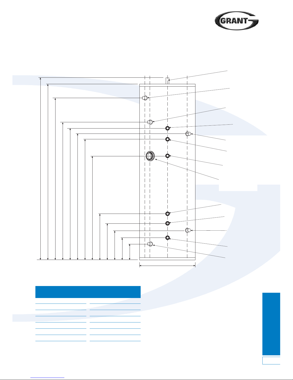
Dims Model
(mm) 300
A 210
B 260
C 325
D 390
E 470
F 970
G 1110
Dims Model
(mm) 300
H 1160
I 1210
J 1225
K 1470
L 1695
M 1745
Dia 580
DuoWave Plus Indirect Cylinder Dimensions
2.2 Dimensions
Figure 2-1: DuoWave Plus indirect solar cylinder dimensions
Dia
ABCDEFGKLHIJ
40˚ 30˚
22mm Hot water
draw off
1
/2" T & P Relief
valve (factory fitted)
22mm Secondary
return
22mm Boiler
return
13/4" Immersion heater
(factory fitted)
Boiler stat pocket
22mm Cold water
inlet
22mm Boiler flow
22mm Solar return
22mm Solar flow
Solar stat pocket
28mm Gravity flow
28mm Gravity return
0˚30˚
M
Page 6
2 Technical Specifications
Technical
Specifications
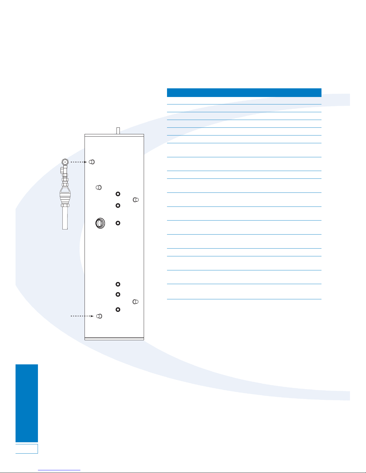
DuoWave Plus Open Vented Cylinder Details
1
17
18
19
2
3
4
5
6
13
7
8
9
10
1211
Item Description Connection Size
1 DHW Out 22mm compression
2 T & P valve connection
1
/2" BSPF
3 Boiler return tapping 22mm compression
4 Secondary return tapping 22mm compression
5 Boiler dual thermostat pocket -
6 Boiler flow tapping 22mm compression
7 Solar heat source return
tapping 22mm compression
8 Solar heat source dual
stat pocket (for dual stat only) -
9 Cold water inlet 22mm compression
10 Solar heat source
flow tapping 22mm compression
11 Immersion heater c/w control
& limit thermostat (factory-fitted) 13/4" BSPF
12 Solid fuel (uncontrolled)
flow tapping 28mm compression
13 Solid fuel (uncontrolled)
return tapping 28mm compression
17 Temperature & Pressure relief 15mm compression
valve - 90°C/7 bar
18 Tundish 15/22mm compression
19 Discharge pipe
(not supplied with cylinder) -
20 Mains water supply pipe
(not supplied with cylinder) -
21 Drain cock
(supplied with cylinder) -
Note:
Pipework between items 17 and 18 not supplied with cylinder.
Figure 2-2: Cylinder connections and controls
2.3 Connections and Controls
6
Page 7

Primary Circuit
Installation
7
3 Primary Circuit Installation
3.3 Auxiliary Primary
Connections
Solar Heating
The Solar flow and return connections
should be made to the bottom 22mm
coil connections. Refer to Figure 5-8.
Other Heat Sources
A third primary heat source should be
connected to the middle coil using the
28mm compression connections.
Please refer to the installation manual
for that appliance.
IMPORTANT. This diagram is shown
as an Illustration of this type of
system only. Reference must be
made to the appliance
manufacturers own instructions for
detailed guidance on the installation
of any uncontrolled appliance.
3.4 Hard Water Areas
If the cylinder is to be used in a hard
water area, we recommend that the
primary flow temperature be limited to
75˚ C. This will help reduce the
migration of suspended solids in the
water and help prevent the build up of
lime scale.
3.1 Grant DuoWave Plus Solar
Cylinders
Grant DuoWave Plus Solar cylinders are
suitable for connecting to most fully
pumped domestic gas or oil fired
central heating boilers working on an
open vented or sealed system having a
maximum working pressure of 3 bar
and a maximum working temperature of
90˚ C. If you are in any doubt
concerning the suitability of the boiler,
consult the boiler manufacturer.
3.2 Boiler Primary Connections
Central Heating
1. The boiler primary flow and return
connections should be made to the
top coil connections. The primary
flow and return fittings are 22mm
compression. The valve has 22mm
compression connections.
2. Locate the dual thermostat in the
stainless steel pocket (refer to
Figure 2-2 for location) and secure
using the retaining screws on the
thermostat housing.
3. Any automatic or manual air vent
fitted to vent air from the upper coil
should be installed on the primary
flow pipe to the coil.
Page 8
Secondary Circuit
Installation
8
4 Secondary Circuit Installation
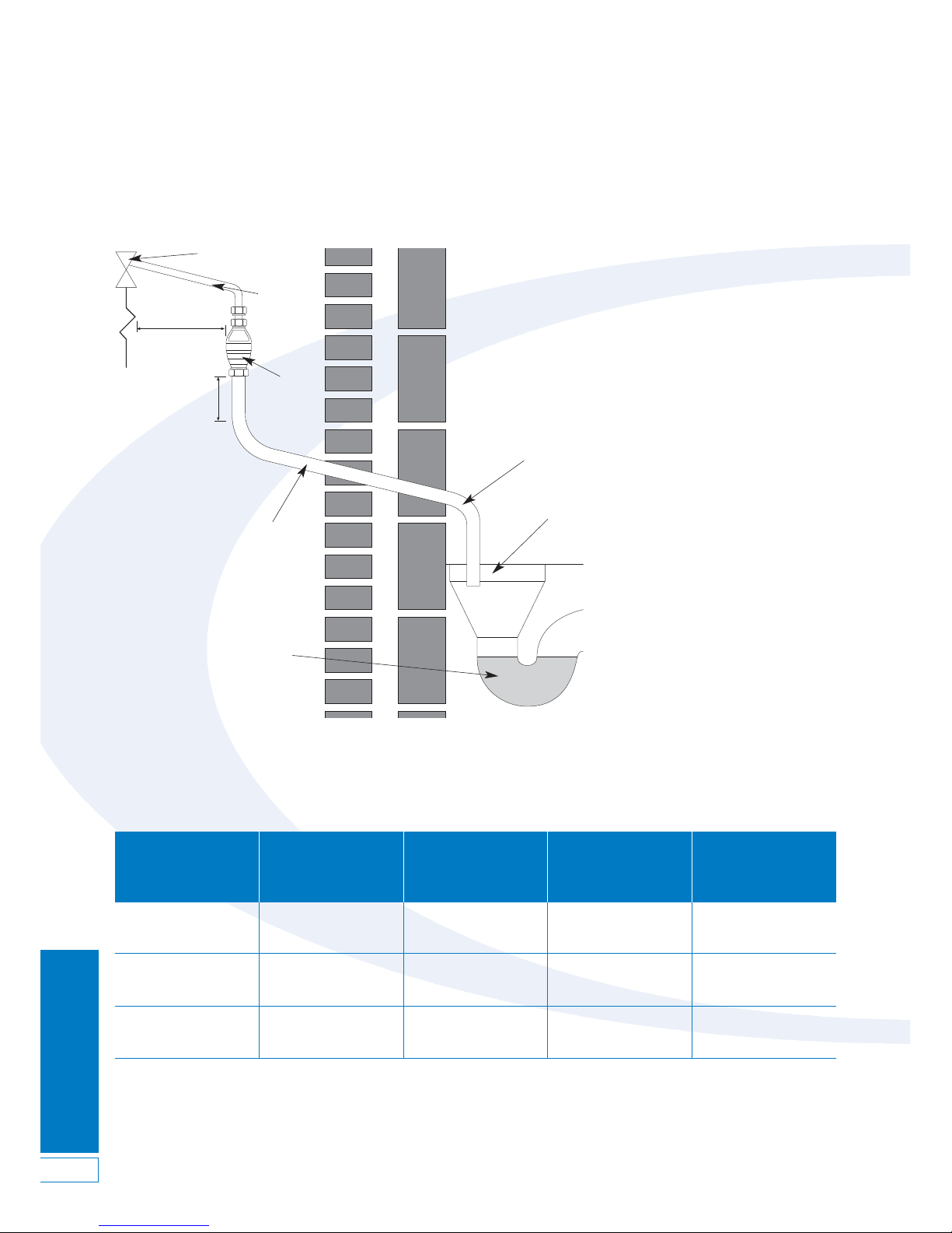
4.1 Discharge Pipe Arrangement
Figure 4-1: Typical discharge pipe arrangement
Safety device ( e.g.
temperature relief valve)
Metal
discharge
pipe from
temperature
Metal discharge pipe from tundish
with continuous fall. See table and
worked example on next page
discharged below
fixed grating
Fixed grating
Trapped gully
Tundish
600mm max
300mm min
4.3 Worked Example
The example below is for a 1/2”diameter
temperature relief valve with a
discharge pipe (D2) having 4 elbows
and a length of 7 m from the tundish to
the point of discharge.
From
Maximum resistance allowed for a
straight length of Ø22mm copper
discharge pipe (D2) from a
1
/2” diameter
temperature relief valve is - 9.0m.
Subtract the resistance for quantity of 4
Ø22mm elbows at 0.8m each = 3.2m.
Therefore, the maximum permitted
length equates to 5.8m.
5.8m is less than the actual length of
7m; therefore calculate the next largest
size.
Maximum resistance allowed for a
straight length of Ø28mm-pipe (D2)
from a
1
/2” diameter temperature relief
valve equates to - 18m.
Subtract the resistance for a quantity of
4 Ø28mm elbows at 1.0 each = 4m.
Therefore the maximum permitted
length equates to 14m.
As the actual length is 7m, a Ø28mm
diameter copper pipe will be
satisfactory.
4.2 Discharge Pipe Sizing
Max resistance allowed,
Minimum size of expressed as a length Resistance created
Valve outlet size, Minimum size of
discharge pipe D2 from
of straight pipe, i.e. no by each elbow or
diameter (inches)
discharge pipe D1 (mm)
tundish in (mm) elbows or bends bend in (m)
22 Up to 9 0.8
1
/2 15 28 Up to 18 1.0
35 Up to 27 1.4
28 Up to 9 1.0
3
/4 22 35 Up to 18 1.4
42 Up to 27 1.7
35 Up to 9 1.4
1 28 42 Up to 18 1.7
54 Up to 27 2.3
Page 9
Secondary Circuit
Installation
9
Cold water
storage cistern
Vent pipe
Insulating jacket
Overflow
warning pipe
If feeding a shower cold feed
to cylinder should always be
above cold water down service
pipe to prevent scolding
450mm
minimum offset
Boiler
primary
Solid fuel
primary
Solar
thermal
Breather with filter
Purpose made
fully fitted lid
Mains water
supply pipe
with isolating
stop valve
Ball valve with
backing plate
Isolating gate valves
close to cistern
Cold water down service pipe
Cold water feed to cylinder
Further isolating gate valves can
be fitted at a more convenient
location if required
To cold water outlet points
To hot water
outlet points
(Diagram of principals only)
Drain cock
4.4 DuoWave Plus 300
The Grant DuoWave Plus 300 Open
Vented Indirect Solar cylinder is
designed to be used as part of a static
Open Vented hot water system. It
should be installed in accordance with
BS6700:2006, The Building Regulations
Part L and also the relevant Water
Regulations – i.e. the Water Supply
(Water Fittings) Regulations 1999 or the
Water Byelaws 2000, Scotland.
Important: This open vented version
of the DuoWave Plus MUST be used if
an ‘uncontrolled’ heat source such as
a solid fuel or wood burning appliance
is to be connected to the cylinder,
along with a ‘conventional’ boiler and
Solar Thermal.
The maximum working head for the
Grant DuoWave Plus Solar cylinder is
30m. Ensure that this is suitable for
your installation before proceeding. If
you are in doubt about the suitability of
the cylinder for the system and
appliances concerned then please
contact the Grant Technical Helpline for
assistance.
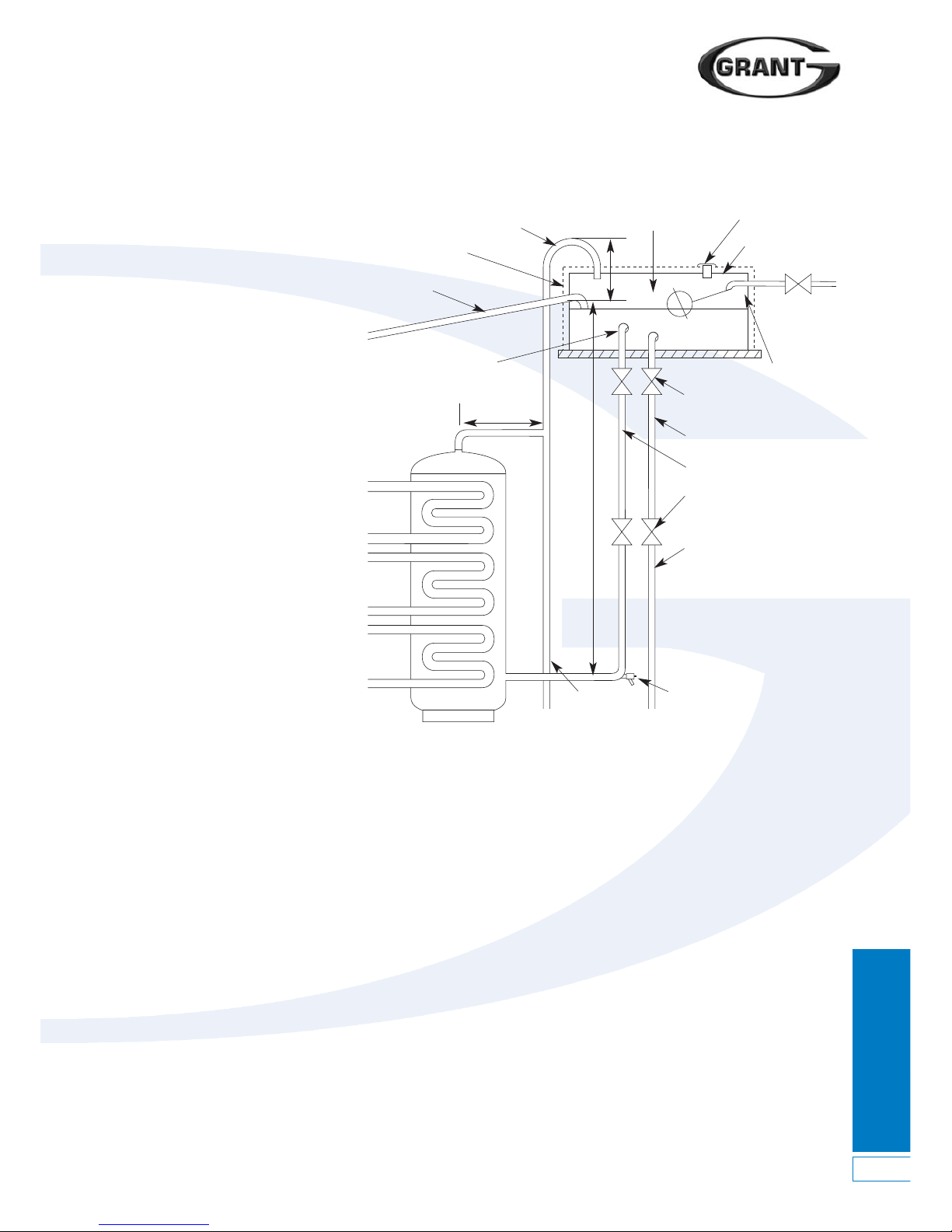
Figure 4-1 shows the installation of the
DuoWave Plus 300 Indirect Solar
cylinder installed as part of an open
vented hot water system.
4.5 Cold Water Storage
Cistern (CWSC)
Cisterns should be installed in
accordance with BS6700:2006 and also
the relevant Water Regulations – i.e. the
Water Supply (Water Fittings) Regulations
1999 or the Water Byelaws 2000,
Scotland.
If the cistern is used to provide cold
water to the hot water supply only, it
should have a capacity at least equal to
the hot water cylinder it is supplying.
4.6 Cold Feed Pipe
The cold water feed pipe from the
CWSC to the cylinder should be sized
in accordance with BS6700:2006. This
feed pipe should not supply water to
any other fitting.
Connect the cold feed pipe to the cold
inlet connection of the cylinder. Refer to
Figure 2-3.
A service valve (quarter turn lever
operated full-bore valve) should be fitted
in the feed pipe in a convenient and
accessible position, e.g. adjacent to the
cylinder. If required a second service
and cold feed pipe should not be
connected together.
Under no circumstances should the
vent pipe from an open vented hot
water cylinder terminate over any
combined feed and expansion cistern
(F&EC) connected to a primary circuit or
any cistern used for the storage and
distribution of wholesome water.
An OSV pipe should be insulated to
protect it from freezing.
4.8 Primary Connections
The ‘uncontrolled’ heat source should
be connected to the middle coil via the
two 28mm compression connections.
The Solar Thermal primary should be
connected to the bottom coil via the
two 22mm compression connections,
with the Boiler primary connected to
the top coil 22mm compression
connections.
All primary pipework should be
insulated between boiler and cylinder.
valve can be fitted in the cold water feed
pipe located adjacent to the CWSC.
A Drain Cock (DC) must be fitted at the
lowest point of this supply pipe
adjacent to the cylinder to enable
draining of the pipe and cylinder.
4.7 Open Vent Pipe
The cylinder must be installed with an
Open Safety vent (OSV) pipe. This must
be connected to the hot water outlet on
the top of the cylinder and rise
continuously to terminate over the
CWSC. Refer to Figure 4-2.
There should be an ‘offset’ of at least
450mm in the OSV pipe to reduce the
tendency for thermal circulation and
loss of heat from the vent pipe. Refer to
Figure 4-1.
The OSV pipe must be of an adequate
diameter, the minimum pipe size being
22mm.
Important: The OSV pipe MUST be
permanently open with NO obstructions
(e.g. no valves fitted). The OSV pipe
H
V
Figure4-2: Open vented cylinder
Page 10
Electrical Installation
10
5 Electrical Installation
All electrical wiring must be carried
out by a competent person and in
accordance with the current I.E.E.
Wiring Regulations.
The control equipment supplied will
ensure that the cylinder functions safely.
From an economic and convenience
point of view, it is intended that these
controls operate in conjunction with
other control packages for example “S”,
or “Y” plan type systems, which
incorporate a programmable time clock,
etc.
5.1 Immersion Heater
All cylinders are supplied fitted with one
immersion heater.
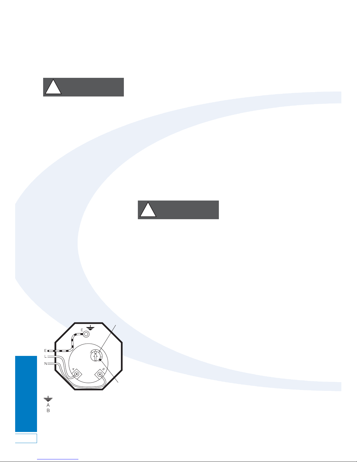
The 3kW 230V 50Hz-immersion heater
should be wired in accordance with the
instructions given in Figure 5-1.
The cable must be routed through
the strain relief bush. The control
thermostat is pre-set at approximately
60°C. The immersion heater conforms
to EEC Directive 76/889 for radio
interference and complies with EN
60335-2-73.
Installation and wiring instructions for
the immersion heater are supplied with
each unit. Follow the wiring instructions
connecting the live, neutral and earth as
indicated.
The unit must be permanently
connected to the electrical supply
through a double-pole isolator. A safety
cut-out is also incorporated within the
thermostat and is factory set to operate
at 80°C ± 5°C.
IMPORTANT
Before resetting the safety cut-out or
altering the thermostat setting, isolate
electrical supply to the unit prior to
removal of the cover. Investigate and
identify the cause of the cut-out
operation and rectify the fault before
manually resetting the cut-out by
pressing in the reset button. Ensure the
cover to the immersion element is
replaced correctly and the retaining nut
is fitted. Finally switch the mains
electricity supply back on.
Figure 5-1: Immersion heater wiring
connections
= Earth (Green/Yellow)
= Live (Brown)
= Neutral (Blue)
Temperature
control dial
Reset
This appliance must be earthed.
!
WARNING
The manual re-set high limit
thermostat must not under any
circumstances be bypassed. This
is pre-set to 80°C and to prevent
nuisance tripping the control
thermostat should always be left in
position 4.
!
WARNING
d) The BEAB approval certification on
this immersion heater only applies if
a Cotherm TSE rod type thermostats
is used. The temperature setting of
the control thermostat should
always be left in position 4.
The control thermostat has an
adjustment range between 25°C and
65°C, however it is recommended that
it is set to 60°C. The overheat
thermostat incorporated within the dual
thermostat will operate at 90°C.
5.2 Immersion Heater Wiring
Instructions
a) Ensure the main’s voltage
corresponds to the voltage rating
of the immersion heater as shown
on the rating label on the terminal
cover.
b) The immersion heater is factory
fitted to the cylinder. If the
immersion heater needs to be
replaced it must be fitted to the
cylinder using the gasket provided
on the unit. Use a shaped spanner,
Stillsons or pipe grips should not be
used. The use of sealing compound
is not recommended.
c) Wire the immersion heater in
accordance with the wiring diagram
(Figure 5-1). It should be wired
through a double pole isolator
switch or controller, with a minimum
break capacity of 13 amp having
contact separation of at least 3
mm, using 1.5mm sq. flexible cable,
85°C rubber insulated HOFR
sheathed, to comply with BS 6141
table 8 and must be fully earthed.
Page 11
Electrical Installation
11
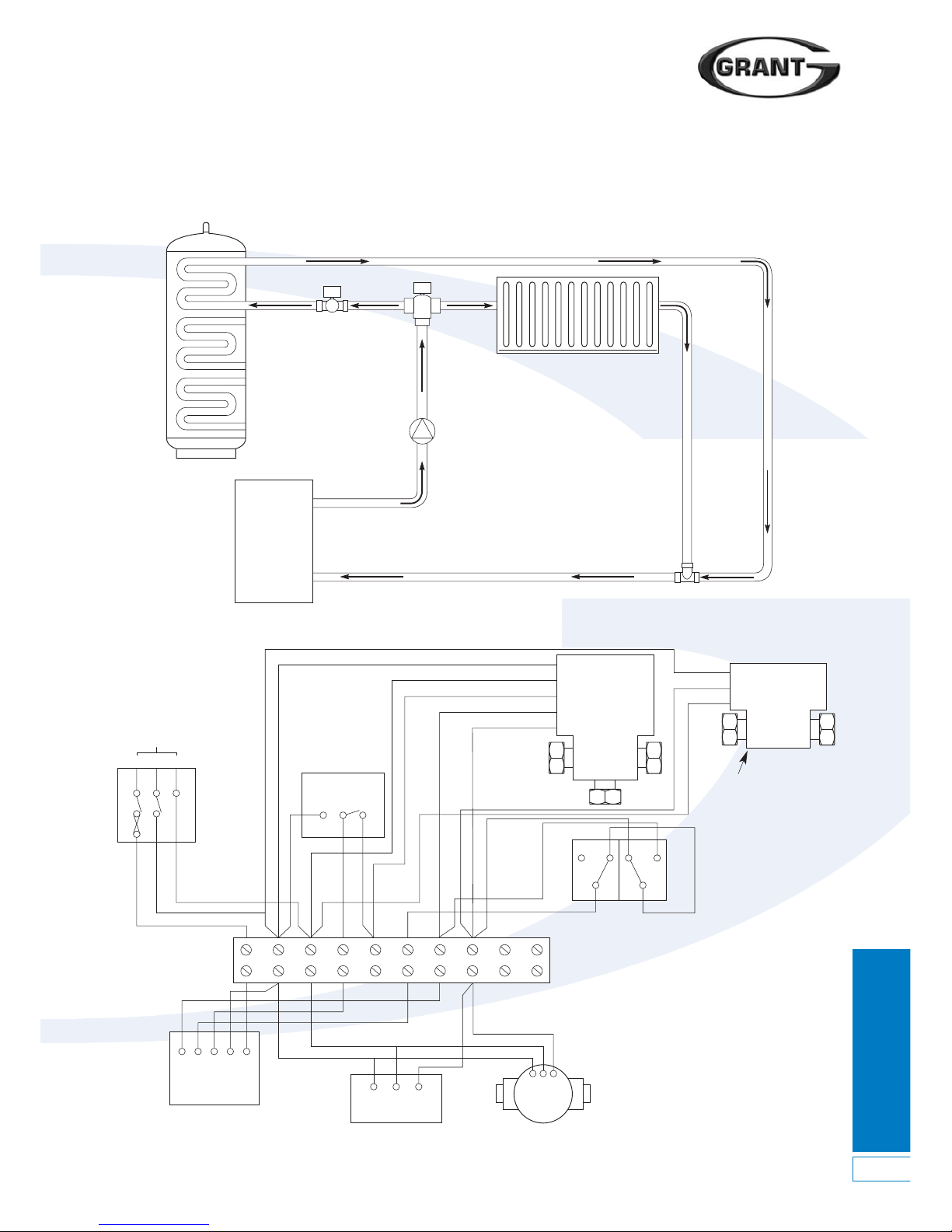
5.3 ‘Y’ Plan System Schematic and Wiring Diagram
Figure 5-2: ‘Y’ Plan system schematic
Figure 5-3: ‘Y’ Plan wiring layout
Boiler
Radiator
Pump
Grant DuoWave Plus
Indirect water cylinder
3 port mid-position valve (not supplied)
Not supplied
230V
50Hz
Room
Thermostat
LNE
2
1
CC
12
123456 7
NEL
NEL
N
HW On
HW Off
HTG
L
8910
2
13
Mid position
zone valve
White
Blue
Grey
Blue
Orange
Brown
Green/Yellow
2 port
zone valve
(supplied)
Green/Yellow
Notes:
1. Orange and grey wires
not required electrically
isolate
2. *2 port valve not
required with open vented
cylinder
High limit Con trol
Cylinder Dual
Thermostat (Top Coil)
Junction box
Time controller
Boiler
Pump
Page 12
Electrical Installation
12
5 Electrical Installation
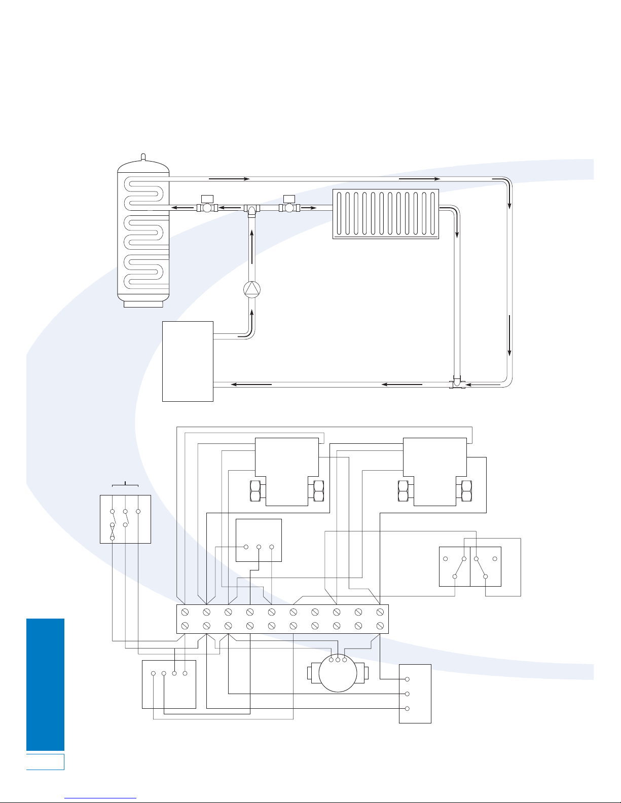
Figure 5-5: ‘S’ Plan wiring layout
5.4 ‘S’ Plan System Schematic and Wiring Diagram
Figure 5-4: ‘S’ Plan system schematic
Boiler
Radiator
Pump
Not supplied
Grant DuoWave Plus
Indirect water cylinder
2 port diverter valve
(not supplied)
Cylinder Dual
Thermostat (Top Coil)
230V
50Hz
Room
Thermostat
LNE
2
1
CC
12
1234567
NEL
NEL
N
HTG
HW
L
8910
2
13
Zone valve
DHW
Zone valve
HTG
Blue
Brown
Green/Yellow
Grey
Orange
Grey
Orange
Blue
Brown
Green/Yellow
High limit Control
Junction box
Time controller
Boiler
Pump
Page 13
Electrical Installation
13
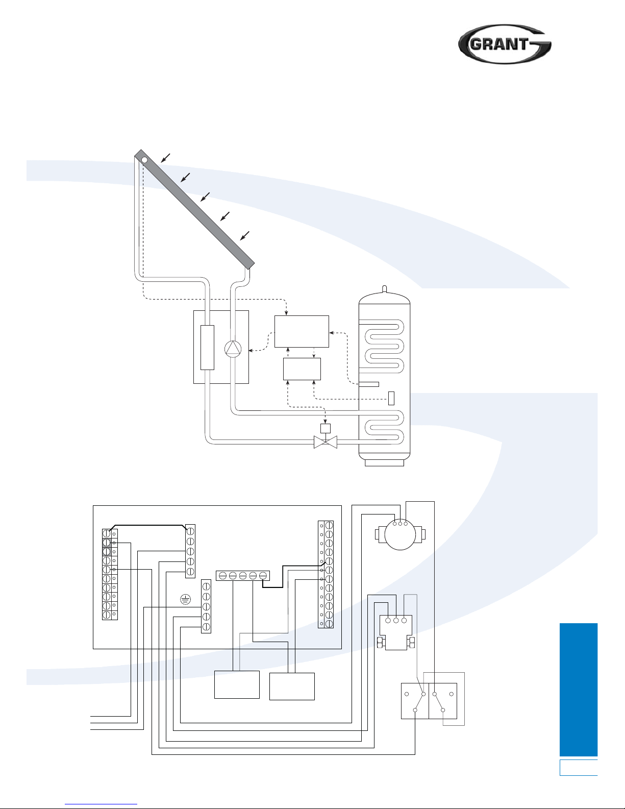
5.5 Solar Thermal Schematic and Wiring Diagram
Figure 5-6: Solar thermal schematic
Figure 5-7: Solar thermal system typical hydraulic wiring layout
Electrical
Junction Box
(not
supplied)
Grant GSD1
Controller
Twin-coil
Cylinder
Solar
Collector
Pump
Station
Collector
sensor
Cylinder
bottom
sensor
N
230V
GND
Sensor
Solar pump
N E L
N E L
Solenoid
valve
Dual thermostat
(Solar coil)
230V 3A
fused supply
L
N
E
1
2
3
4
5
6
7
8
9
10
11
12
13
14
15
16
17
18
19
20
21
22
Grant GSD1 Mk2 Controller
1
CC
122
C ontrolHigh Limit
Page 14

Commissioning,
Draining Down & Safety
14
6
Commissioning, Draining Down & Safety
6.1 Filling the Cylinder
IMPORTANT
Before filling the cylinder check that the
immersion heater has not loosened in
transit. Tighten as necessary using a
shaped spanner. Stillsons or pipe grips
should not be used.
1. Open all hot water taps.
2. Turn on the stop cock.
3. When water flows from all taps
close the taps.
4. Allow system to stabilise for five
minutes.
5. Open each hot water tap in turn to
expel air from the system pipe work.
6. Check for leaks.
7. Manually operate Temperature and
Pressure Relief Valve (17) - Figure
2-2, to ensure free water flow
through discharge pipe. (Turn knob
to left).
6.2 Draining Down
Switch the electrical power off
(important to avoid damage to element).
Isolate boiler from DuoWave Plus unit.
Turn off the cold water supply valve
(stop cock). Open hot water taps. Open
drain (21) - Figure 2-2. The unit will
drain.
6.3 Safety Cut-Out
1. The safety cut-out operates if:
a. Wiring is incorrect.
b. The immersion heater thermostat or
cylinder thermostat fails.
c. Thermostat is set too high.
2. Remember before resetting the
safety cut-out or altering the
thermostat setting, isolate electrical
supply to the unit prior to removal
of the electrical box lid.
3. Reduce thermostat setting and
press the reset button. After
adjustments are completed, ensure
the lid to the electrical box is
replaced correctly and the retaining
screw is fitted.
4. If the problem persists, please
contact your installer in the first
instance.
6.4 Hot Water Discharge from
Tundish
There are three reasons why hot water
will discharge from the tundish:
1. Thermal cut-out has malfunctioned.
2. The control thermostat has
malfunctioned.
3. The T & P valve is letting by.
In all cases, should a repair be
necessary, the work must be carried
out by a competent person.
Isolate the cylinder from all electrical
supplies before commencing
maintenance work.
6.5 Customer Handover
1. Explain the operation of the system
to the User, referring to Section 10
of these instructions.
2. In particular, make the User aware
of what to do if water is seen to
flow from either the T&P Valve.
Refer User to the Information given
in Section 10.
Page 15

7 Maintenance
Maintenance
15
7.1 Servicing and Maintenance
1. Servicing and maintenance must
only be carried out by a competent
hot water installer, or by Grant
Engineering (IRL) Ltd authorised
personnel.
2. Before any work whatsoever is
carried out on the installation, it
MUST first be isolated from the
main’s electricity supply.
Both the primary and secondary
systems will contain very hot water
that will scald; therefore care should
be taken when opening any joints,
seals or valves.
3. Only use spare parts authorised by
Grant Engineering (IRL) Ltd. The
use of unauthorised spare parts will
invalidate the warranty.
4. Drain the cylinder – When draining
the cylinder, always switch off the
boiler and the immersion heater
first. Turn off the water supply at the
mains stopcock.
Connect a hose pipe to the drain
cock (see Figure 2-2) and route it to a
convenient gully. Open the drain cock
and all hot taps that are served by the
cylinder. The cylinder may take
several minutes to empty completely.
5. In hard water areas it may be
necessary from time to time to
remove and de-scale the immersion
heater element. Replace the gasket
each time it is removed.
!
WARNING
6.
Whilst the hose pipe is connected, the
drain cock open and with the
immersion heater removed, the
cylinder may be flushed out to remove
any debris, sand or lime scale particles
that may have collected in the bottom
by using a further hose pipe
connected to the cold water main.
7. Close the drain cock, disconnect
the hose, refit the immersion heater
and close all hot water taps before
reopening the stopcock. Allow the
cylinder time to fill whilst checking
for any leaks. Release any air from
the system by opening each hot
water tap individually, starting with
the one furthest from the cylinder.
8. Manually lift the expansion relief and
temperature, every 12 months
(more frequently in hard water
areas) to prevent debris from
building up behind the valve seat.
Whilst carrying out this operation,
check that the discharge to waste
is unobstructed. Check that each
valve seals correctly when released.
As the valves are pre-calibrated,
they require no further maintenance.
9. Finally switch on the mains
electricity supply to the immersion
heater and the boiler. As the system
heats up, check again for any leaks
and rectify as necessary.
Page 16
Fault Finding Guide
16
8 Fault Finding Guide
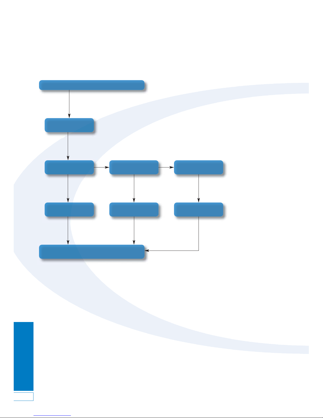
8.1 Intermittent Water Discharge
Intermittent Water Discharge from T & P Valve
Test for correct operation. If water is still
discharging, contact a competent Engineer
Thermostat Failure
Immersion Thermostat
Failure
Primary Cylinder
Thermostat
Faulty T & P
Valve
Repair or Replace
Immersion Thermostat
Repair or Replace
Thermostat
Replace T & P
Valve
Yes Yes Yes
No No
Page 17
Fault Finding Guide
17
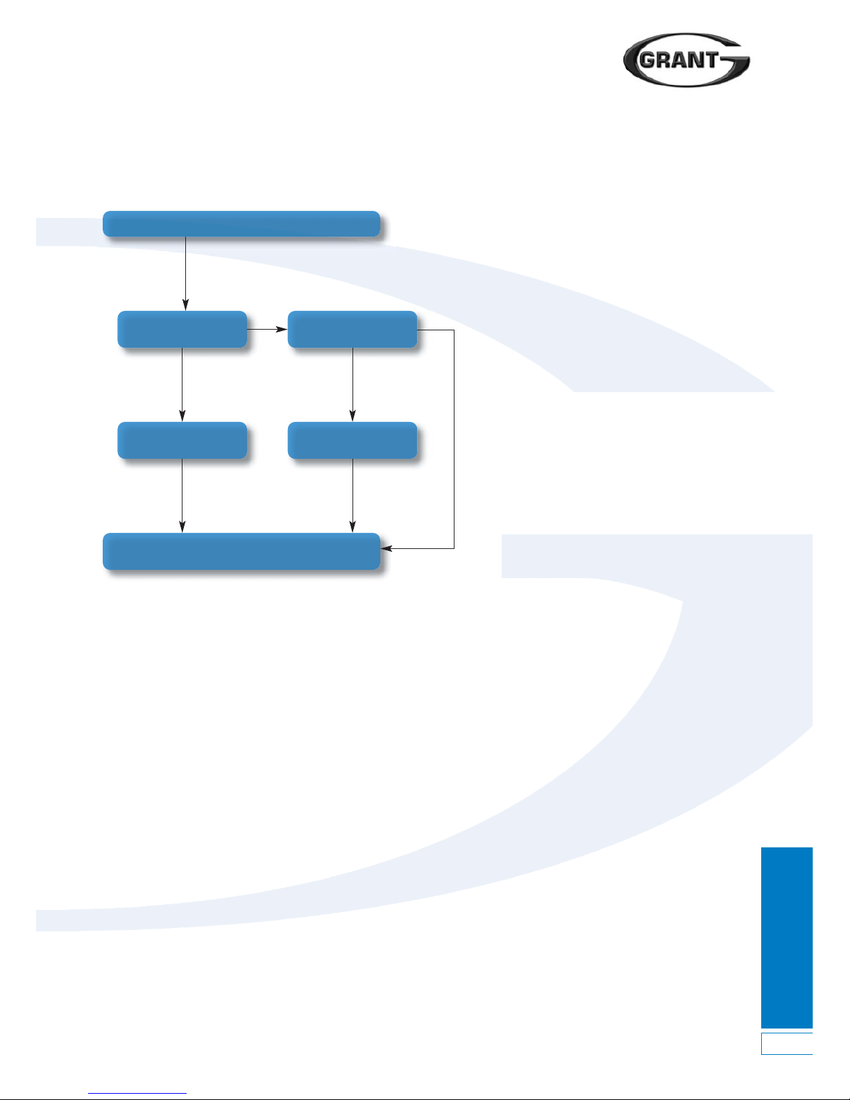
8.2 Constant Water Discharge
Constant Water Discharge from T & P Valve
Test for correct operation. If water is still
discharging, contact a competent Engineer
Faulty T & P
Valve
Faulty Pressure
Reducing Valve
Replace T & P
Valve
Replace Pressure
Reducing Valve
Yes Yes
Yes Yes
No No
Page 18
Fault Finding Guide
18
8 Fault Finding Guide
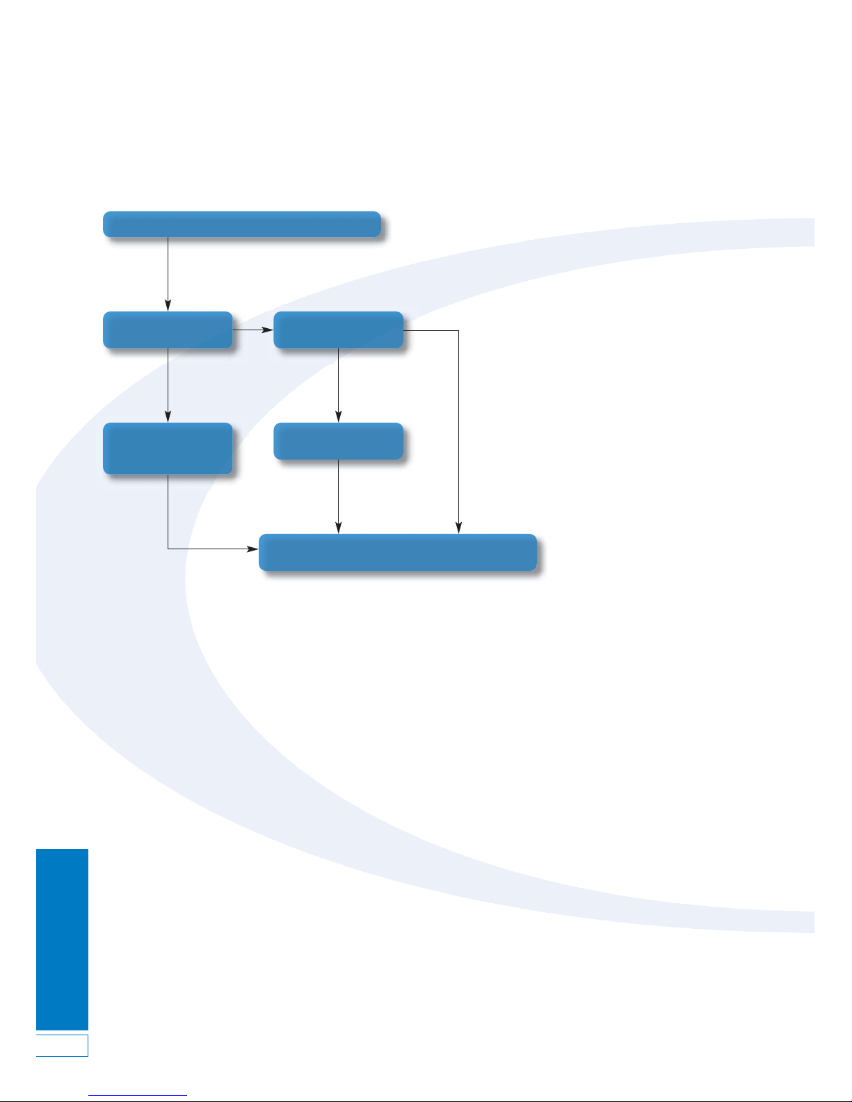
8.3 No Flow from Hot Water Taps
No Flow from Hot Water Taps
Mains Supply
Disconnected?
Test for correct operation. If water is still
not flowing, contact a competent Engineer
Open supply valve or
wait for supply to be
reconnected
Mains Supply
Disconnected?
Repair or Replace
Thermostat
No
Yes
Yes
Yes
No
Page 19
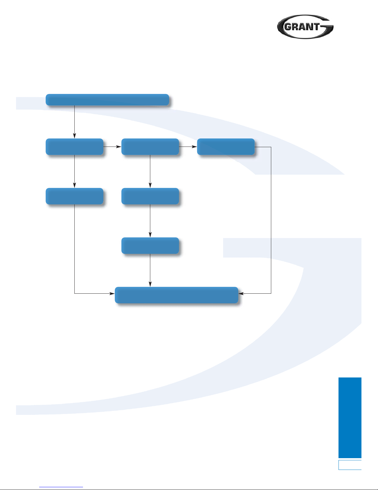
Fault Finding Guide
19
8.4 Cold Water Flow from Hot Water Taps
Cold Water from Hot Water Taps
Is Programmer calling
for Hot Water?
Check and Set Hot
Water setting
Is Motorised Valve
working?
Is Boiler working?
Is Cylinder Stat
Calling for Heat?
Yes
No No
No
No
Yes Yes
Test for correct operation. If water is still
cold, contact a competent Engineer
Check and Replace
Cylinder Thermostat
Page 20
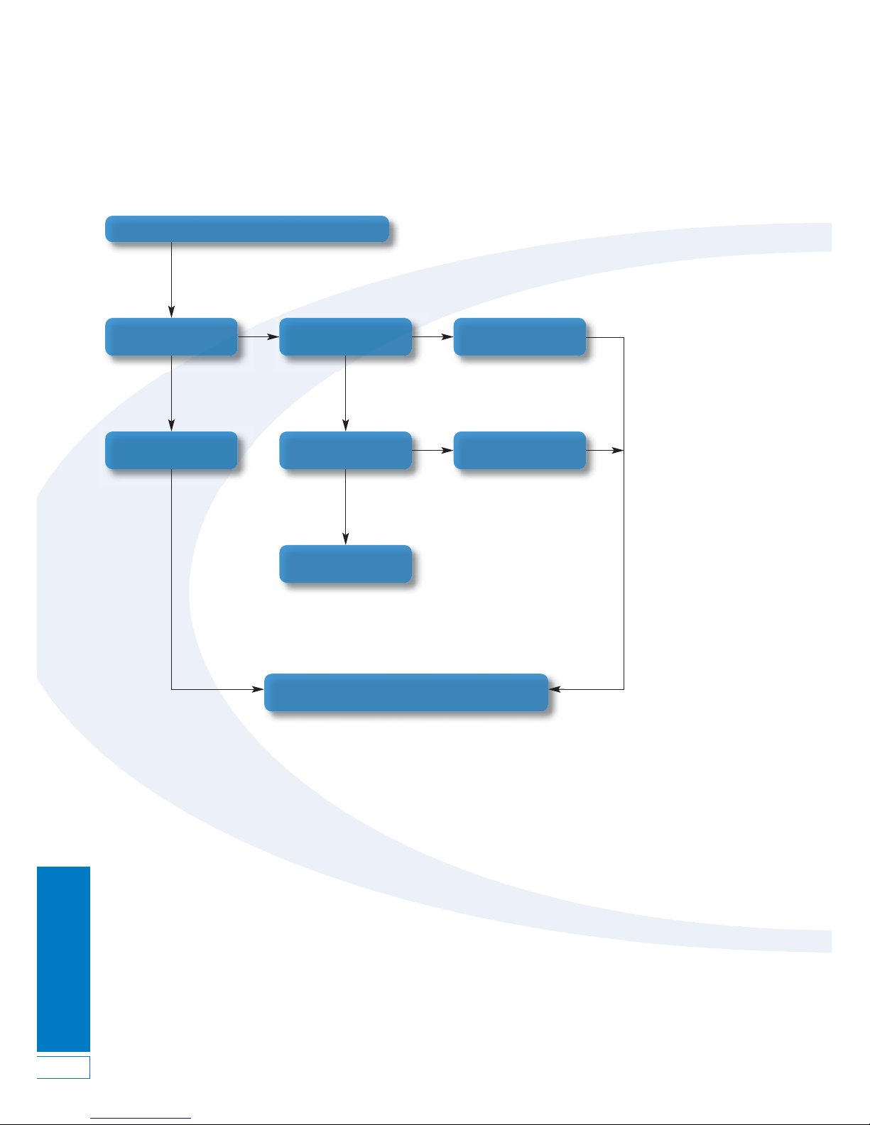
Fault Finding Guide
20
8.5 Excessive Hot Water from Taps
Excessive Hot Water from Taps
Is Cylinder Thermostat
set too high?
Reduce Thermostat
Setting
Is System Wiring
correct?
Correct Wiring as
per instructions
Is Cylinder Thermostat
Operating?
Replace Cylinder
Thermostat
No
Yes Yes
Yes
No
No
Test for correct operation. If water is still
cold, contact a competent Engineer
Fault. Contact
Engineer
8 Fault Finding Guide
Page 21

User Instructions
21
9 User Instructions
9.1 User Instructions
1. Your Grant DuoWave Plus Solar
vented hot water cylinder has been
designed to give many years of
trouble-free service and is made
from hygienic high grade stainless
steel. All models include a 3 kW
electric immersion heaters for times
when your central heating is
switched off, during the summer
for instance.
2. The flow temperature of the hot
water can be set to your
requirements on the immersion
heater up to 60°C and the indirect
system dual thermostat up to 65°C.
These temperatures should not be
set any higher otherwise nuisance
tripping of the high limit thermostat
will occur. If you are in any doubt,
these adjustments should be best
left to a qualified electrician.
3. When you first fill a basin the water
may sometimes appear milky. This
is due to very tiny air bubbles in the
water, which will clear very quickly.
If water is seen to flow from the
Temperature & Pressure Relief (T&P
Valve) valve on the cylinder seek
expert advice immediately.
If the water is flowing from the T&P
Valve, immediately:
Shut off the electrical supply to the
immersion heater(s)
Shut down the boiler
Switch off ALL other heat sources to
the cylinder e.g. solar, etc.
DO NOT SHUT OFF THE WATER
SUPPLY TO THE CYLINDER.
Contact your installer to check the
system.
IMPORTANT
Do NOT tamper with any of the Safety
controls fitted to the cylinder. If you
suspect a fault always contact a
COMPETENT installer who is
QUALIFIED to work on water
cylinders.
!
WARNING
Page 22

User Instructions
& Warranty
22
10 Warranty
10.1 The Grant Cylinder
Warranty
Dear Customer
You are now the proud owner of a
Grant Cylinder from Grant Engineering
(IRL) Ltd, which has been designed to
give you years of reliable, trouble free
operation.
Grant Engineering (IRL) Ltd guarantees
all electrical and mechanical
components supplied with the cylinder
for a period of one year from the date
of purchase. In addition, the stainless
steel used in the manufacture of the
cylinder is guaranteed for a period of
twenty five years with the manufacturing
process of the cylinder guaranteed for
one years from the date of purchase,
provided that the cylinder is installed in
full accordance with the installation
instructions provided and the system is
serviced after twelve months operation.
(see Terms and Conditions).
Breakdown during the
Manufacturer’s Warranty
If your Grant Cylinder should fail during
the first year, you must contact Grant
Engineering (IRL) Ltd, who will arrange
for the repair under the terms of their
Warranty, providing that the system has
been correctly installed and
commissioned, and the fault is not due
to misuse, or the failure of any external
components not supplied by Grant IRL
Ltd (e.g. pipework, etc.).
In the first Instance:
Contact your installer or commissioning
engineer to ensure that the fault does
not lie with the system or any other
components, or any incorrect setting of
the system controls.
If a Fault is Found:
Ask your installer to contact Grant
Engineering (IRL) Ltd, Service
Department on 057 9120089 who will
arrange for a qualified service engineer
to attend to the fault.
Free of Charge Repairs:
During the first year no charge for parts
or labour will be made providing that
the Cylinder has been installed and
commissioned correctly in accordance
with the manufacturer’s instructions and
serviced at twelve month intervals.
Proof of ‘purchase’ date must be
provided upon request.
Chargeable Repairs:
A charge will be made if the cause of
the breakdown is due to any of the
following:
• Faults caused by the plumbing or
heating system, external electrics
and external components.
• The Grant Cylinder has not been
commissioned, or serviced in
accordance with the installation
and servicing manual.
• The system has been installed for
over one year.
Terms of Manufacturer’s Guarantee
1. The Grant Cylinder guarantee starts
from the date of purchase.
2. All electrical and mechanical
components supplied with the
Grant Cylinder are guaranteed for a
period of one year. The stainless
steel used in the manufacture of the
cylinder is guaranteed for a period
of twenty five years with the
manufacturing process of the
cylinder guaranteed for one year.
4. The Grant Cylinder must be installed
by a competent/licensed installer
and in accordance with the Codes of
Practice and Regulations in force at
the time of the installation.
5. The Grant Cylinder and its
components must not have been
modified or tampered with.
6. The installation must be serviced
every twelve months as per the
installation instructions. (Receipts
should be kept as proof).
7. The Grant Cylinder must be
connected to a mains water
supply (installations utilising a
private water supply are not
covered by this guarantee).
8. Breakdown/failure due to lime-scale
will not be covered by this
guarantee.
9. The Grant Cylinder must not be
sited in a location where it may be
subjected to frost.
10. All claims under this guarantee
must be made to Grant Engineering
(IRL) Ltd prior to any work being
undertaken. Proof of purchase and
date of installation must be
provided on request. Invoices for
call out/repair work by any third
party will not be accepted unless
previously authorised by Grant
Engineering (IRL) Ltd.
11. This guarantee is transferable
providing the installation is serviced
prior to the dwelling’s new owners
taking up residence. Grant
Engineering (IRL) Ltd must be
informed of the new owner’s details.
12. Grant Engineering (IRL) Ltd will
endeavour to provide prompt service
in the unlikely event of a problem
occurring, but cannot be held
responsible for any consequence of
delay however caused.
13. This guarantee applies to Grant
Cylinders installed in the Republic of
Ireland and Northern Ireland.
Provision of in-warranty cover
elsewhere is subject to agreement
with Grant Engineering (IRL) Ltd.
Page 23

Notes
User Instructions
& Warranty
23
Page 24

GRANT ENGINEERING (IRELAND) LTD
Crinkle, Birr, Co. Offaly, Ireland
Tel: (057) 91 20089 Fax: (057) 91 21060 Email: [email protected] www.grantengineering.ie
This manual is accurate at the date of printing but will be superseded and should be disregarded if specifications and/or appearances are changed in the interests of continued product improvement.
All good sold are subject to our official Conditions of Sale, a copy of which may be obtained on application. © Grant Engineering (Ireland) Limited 2008. No part of this manual may be reproduced by any means without prior written consent.
 Loading...