

Shaking water bath
OLS200
Refrigerated immersion
cooler
CS200G
Operating Manual

1 Safety 2
2 Getting Started 3
2.1 Unpacking 3
2.1.1 Shaking bath - OLS200 3
2.1.2 Universal Tray 3
2.1.3 Test Tube Tray 3
2.1.4 Cooler - CS200G 3
2.1.5 Cooling coil - CW200 3
2.2 Installation 3
2.2.1 Location 3
2.2.2 for operating temperatures below ambient 3
2.2.3 for operating temperatures above 60°C 3
2.2.4 Fitting the trolley 4
2.2.5 Fitting the tray 4
2.2.6 Filling 4
2.2.8 Connection to electrical supply 4
3 Operation 5
3.1 OLS 200 5
3.1.1 Controls and indicator lamps 5
3.1.2 Setting the temperature 5
3.1.3 Shaking 6
3.1.4 Setting the overtemperature cut-out 7
3.1.5 Draining 7
3.2 CS200G 7
4 Accessories 7
4.1 Universal tray UT200 7
4.2 Plain Tray UTP 7
4.3 Tray for test tube racks TT200 8
4.4 Perforated tray for use as an ordinary unstirred bath SBT28 8
4.5 Gabled lid, stainless steel LS200 8
5 Fault diagnosis 9
6 Technical specification 10
6.1 OLS200 orbital/linear shaking bath 10
6.2 CS200G refrigerated cooler 11
7 Maintenance and service 11
7.1 OLS200 Shaking bath 11
7.2 Refrigerated cooler: CS200G 11
7.3 Replacement of fuses 12
7.3.1 OLS200 Shaker bath 12
7.3.2 Refrigerated cooler: CS200G 12
8 Guarantee 12
9 Service 12
10 Compliance 13
10.1 Disposal & WEEE 13
10.2 RoHS Directive 13
10.3 Electrical safety and Electromagnetic compatibility 13
OLS200, CSG200 15214 Ver 9 - January 2010 57U
Operating Manual Page 1 www.grant.co.uk
1 Safety
The following symbols marked on the equipment mean:-
Caution: Read these operating instructions fully before use and pay particular attention to sections
containing this symbol
Caution: Surfaces can become hot during use.
Always observe the following safety precautions
Use only as specified by the operating instructions or the intrinsic protection may be impaired.
After transport or storage in humid conditions, dry out the unit before connecting it to the supply
voltage. During drying out the intrinsic protection may be impaired.
Connect only to a power supply with a voltage corresponding to that on the serial number label.
Connect only to power supply which provides a safety earth (ground) terminal.
Before moving, disconnect at the power supply socket. Do not remove the IEC connector.
Do not check the temperature by touch; use the temperature display or a thermometer.
To reduce the risk of eye injury during high temperature operation, use safety goggles or spectacles.
Do not touch surfaces which become hot during high temperature operation.
Ensure that the operating temperature is less than the maximum operating temperature of your
sample material.
Set the adjustable overtemperature cut-out after setting or changing the set temperature, and reset it
at monthly intervals to check that the cut-out is operating correctly.
Ensure that the mains switch is easily accessible during use.
Do not block or restrict ventilation slots.
If liquid is spilt inside the unit, disconnect it from the power supply and have it checked by a
competent person.
It is the user’s responsibility to carry out appropriate decontamination if hazardous material is spilt on
or inside the equipment.
Do not connect to a power supply or switch on before filling the tank.
Take care when topping up or draining, as the liquid in the tank may be very hot.
If the alarm lamp is illuminated do not touch the liquid or the heater, they may be very hot. Refill
carefully, a hot heater can cause a spattering of very hot water droplets and scalding steam.
Always use a lid when operating above 60°C. Take care when rising and removing the lid, it may be
hot. Steam and hot vapours can cause scalding.
Drain before moving the bath. Before draining allow the liquid to cool to below 50°C or heat to above
10°C.
Use only liquids specified in the operating instructions, within the specified temperature range. If the
alarm lamp is illuminated the liquid temperature may be above its recommended maximum: do not
inhale the vapours given off as they may be toxic; liquids should be safely discarded and replaced.
OLS200, CSG200 15214 Ver 9 - January 2010 57U
Operating Manual Page 2 www.grant.co.uk

2 Getting Started
2.1 Unpacking
Remove the packing materials carefully, and retain for future shipment or storage.
2.1.1 Shaking bath - OLS200
The pack should contain:
shaking bath
trolley
drive magnet
drain insert (located in a clip on the rear panel of OLS200)
mains cable
these instructions.
2.1.2 Universal Tray
Tray fitted with springs for use with flasks.
2.1.3 Test Tube Tray
Tray for use with test tube racks.
2.1.4 Cooler - CS200G
Refrigerated immersion cooler, for operating temperatures down to 0°C.
2.1.5 Cooling coil - CW200
For operating temperatures at or below ambient, a Grant CW200 heat exchange coil can be used
to maintain the temperature at 2°C above the temperature of the coolant.
2.2 Installation
2.2.1 Location
Position the bath on a firm level surface with the controls facing the operator and adjust the
position of the feet so that the bath stands level. This can be done after filling with liquid to the top
of the trolley, and levelling the water against the top of the trolley as a reference. It is necessary
that the bath is level in order to achieve optimum performance.
2.2.2 for operating temperatures below ambient
The unit is insulated for use at temperatures below ambient. It is recommended that the gabled lid
is used to reduce heat gain.
To fit the cooling coil: remove the flask tray and trolley, then remove the base tray by undoing the
retaining 'N' nuts (see figures 1 and 5).
CS200G: Stand the CS200G next to the OLS 200 and position the cooling coil in the bottom of the
tank, ensuring that it lies flat, with the feed pipe at the rear.
CW200: Place the CW200 cooling coil in the bottom of the tank, ensuring that it lies flat, with the
input and output pipes at the rear.
To secure the cooling coil in position, replace the base tray and washers and tighten the four
retaining 'N' nuts (see figure 5).
Ensure that the CS200G is located so that the ventilation grilles are not less than 100mm from
any obstruction.
To use the lid: remove the slot cover and replace in the alternative position, to allow the
connecting pipe to pass through.
2.2.3 for operating temperatures above 60°C
At operating temperatures above 60°C a lid MUST be fitted. The Grant sloping stainless steel lid
directs condensate into the bath to prevent it from dripping into open flasks or tubes.
OLS200, CSG200 15214 Ver 9 - January 2010 57U
Operating Manual Page 3 www.grant.co.uk

0 to + 5C
80% water, 20% antifreeze (inhibited ethylene glycol)
WARNING: ANTIFREEZE IS TOXIC. IT IS HARMFUL IF SWALLOWED.
READ THE SUPPLIERS’ HANDLING INSTRUCTIONS.
+5C to 99C
Water (taps or distilled). See maintenance and service section 7.
2.2.4 Fitting the trolley
Caution: The shaker uses a magnet located in the bottom of the tank. Once removed from the
bath the drive magnet produces a strong magnetic field and it should be placed in a position
where it cannot affect computer discs, cassettes, watches, etc. If your watch is susceptible to
magnetic fields, please remove it before removing or fitting the trolley. Once the trolley and drive
magnet have been fitted the stray magnetic fields are very small.
Fit the drive magnet onto the shaft in the bottom of the bath (see figures 1 and 2). Lower the
trolley into the bath, keeping it level, with the drive arm facing the front of the bath (see figure 4);
fit the drive arm pin into one of the holes on the drive magnet. See figure 1 and paragraph
3.1.3.2.2 for guidance as to which hole to select. If the drive arm is not parallel to the base of the
tank, it may be difficult to fit the pin into the hole.
2.2.5 Fitting the tray
The OLS200 shaking bath provides both linear and orbital shaking motion. Select the type of
motion you require by altering the position of the tray in the tank.
The tray is punched with a 'O' and a ' ' (see figure 3). For orbital motion, position the 'O'
nearer the front. For linear motion, position the ' ' nearer the front.
For orbital motion: tilt up the far end, locate the near end lip on the wheels nearest to you. Lower
the far end and move the trolley sideways until the pin locates in the hole in the drive arm (see
figure 4).
For linear motion: tilt up the far end, insert the near end lip between the locating strips on the
trolley (see figure 4). Lower the far end.
To remove the tray: hold both handles and keep the tray level as you lift it.
WARNING: For safety, do not remove the tray from the unit when the liquid is hot.
2.2.6 Filling
Before filling ensure that the drain pipe is not attached.
Fill the bath without the tray fitted, with approximately 9 litres of liquid. Fit the tray and adjust the
liquid level to the required immersion depth. When the liquid is level with the top of the tray the
flask immersion depth is 50mm.
DO NOT operate the bath without any liquid.
2.2.7 Specified liquids:
Do not use any other liquids without consulting Grant Instruments.
2.2.8 Connection to electrical supply
WARNING: The equipment must be earthed (grounded). It is protected by internal electrical
fuses. We strongly recommend that the power supply to any equipment for heating liquids should
include a residual-current circuit breaker (earth leakage trip).
Check that the voltage rating of the products, given on the serial number plate at the power cable
entry, is correct for your supply.
Fit the mains cable into the IEC power socket at the rear of the unit(s).
Connect the plug to the power supply socket.
OLS200, CSG200 15214 Ver 9 - January 2010 57U
Operating Manual Page 4 www.grant.co.uk
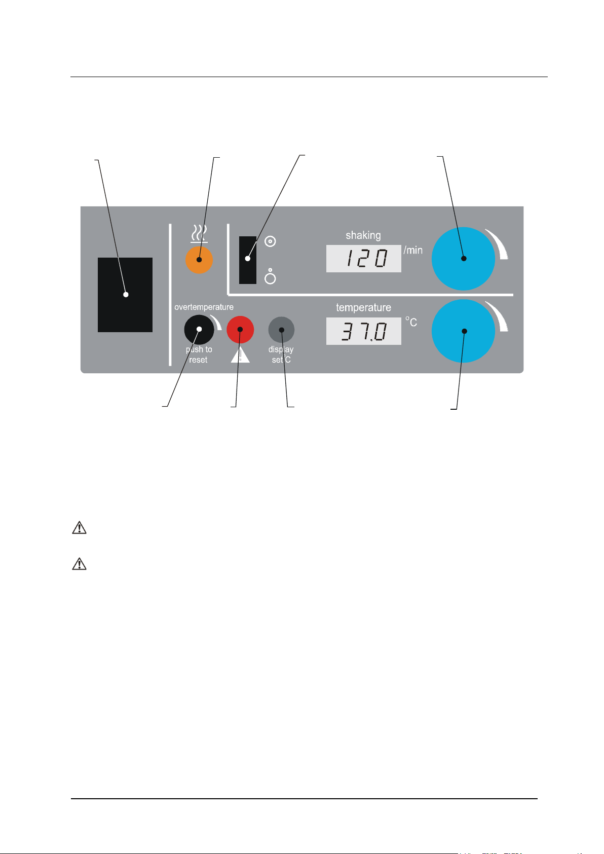
Power
Switch
Heater
Lamp
Shaking
Switch
Shaking
Knob
Temperature
Knob
Display
Set Button
Alarm
Lamp
Push to
Reset
Knob
3 Operation
3.1 OLS 200
3.1.1 Controls and indicator lamps
The temperature display normally shows the liquid temperature in C.
When the display set C button is pressed the set temperature is shown.
The temperature C control knob sets the required operating temperature.
Heater lamp (orange) indicates when the heater is on. While the bath is warming up, the lamp is
on continuously. As the temperature approaches set point, the lamp starts to flash, and continues
to flash intermittently while the unit is controlling at set temperature.
Alarm lamp (red) illuminates when the overtemperature cut-out has operated.
The overtemperature push to reset knob sets the overtemperature cut-out. The cut-out
operates if the liquid temperature rises above its set temperature. When it has operated, the red
alarm lamp illuminates and the heater is switched off. The temperature of the liquid continues to
be displayed to warn of possible high temperatures.
The speed display shows shaking speed in revolutions per minute. In linear motion the number of
strokes is twice the number displayed.
The shaking/min knob sets the shaking speed.
3.1.2 Setting the temperature
The display normally shows the liquid temperature. To show the set temperature at any time,
press the display set °C button. To set the required operating temperature, push the display set
C button, whilst turning the temperature °C knob until the required temperature is indicated on
the display.
OLS200, CSG200 15214 Ver 9 - January 2010 57U
Operating Manual Page 5 www.grant.co.uk

Flask
size ml
No. flasks
Linear
18mm stroke
Hole ‘A’
Max. speed
strokes/min
Linear
28mm stroke
Hole ‘B’
Max. speed
strokes/min
Linear
36mm stroke
Hole ‘C’
Max. speed
strokes/min
Orbital
Hole 'A'
Max. speed
rpm
1000
1
300
270
180
160 3 220
200
170
130 500
1
340
220
200
190 6 260
170
120
135 250
1
380
270
180
200
11
280
200
140
145 100 1
200
18 145 50 1 360
300
170
200
28
260
200
140
150
3.1.3 Shaking
Switch on shaking. In linear motion the number of strokes/minute is double the number displayed.
To set the required revolutions per minute, turn the shaking/min knob until the required speed is
displayed. The speed rises slowly to the set value. Following adjustment, the setting should be
checked after several minutes. Stroke length for linear movement
The stroke length in linear motion can be altered according to your requirement with a choice of
three settings. The setting can be changed by altering the position of the drive arm pin in the drive
magnet (see figure 1). Hole ‘A’ sets the stroke length at 18mm; there are three alternative
positions of hole ‘A’, any of them may be used. Hole 'B' sets the stroke length at 28 mm and Hole
'C' sets the stroke length at 36 mm. See figure 1 for identification of holes.
Orbital motion operates ONLY at 9mm radius.
Maximum speed
The maximum speed depends on number and size of flasks, liquid depth, operating temperature
and, in linear motion, stroke length. The maximum speed will need to be determined for each
individual application. To determine the maximum speed, increase the speed until the trolley
begins to move erratically or stop; switch the shaking off, turn the speed down and restart. By
repeating this procedure the speed can be fine tuned to a maximum point, just below the point at
which it de-latches. The shaking trolley is driven by a drive magnet coupled to a rotating magnet
below the tank; as the speed is increased a point is reached where the magnetic coupling de-
latches, causing the trolley either to move erratically or to stop.
Liquid depth
Maximum speed is achievable with the minimum liquid depth.
Liquid depths up to a maximum of 130mm (90mm flask immersion) can be used, but water may
splash out at high speeds, particularly with a small number of large vessels.
Flasks, stroke length
The following table gives a guide to the maximum speeds obtainable with 50mm immersion
depth, three different stroke lengths and various sizes and numbers of Erlenmeyer flasks.
OLS200, CSG200 15214 Ver 9 - January 2010 57U
Operating Manual Page 6 www.grant.co.uk

3.1.4 Setting the overtemperature cut-out
To protect both the unit and your samples, the overtemperature cut-out should be set each time
the required operating temperature is changed. Turn the overtemperature push to reset knob
fully clockwise and press to reset. The cut-out is now set at its maximum. Allow the bath to
stabilise at the required operating temperature. Turn the control slowly anticlockwise using a
screwdriver until the red alarm lamp comes on. Press the knob and gently turn clockwise until the
alarm lamp goes out. Turn the knob anticlockwise three quarters of the way back towards the
point where the alarm lamp came on. The overtemperature cut-out is now set approximately 10°C
above the required operating temperature.
Note: When the cut-out has operated, the bath needs to cool to below the set temperature before
the cut-out can be reset. Push the knob to reset the cut-out.
3.1.5 Draining
Allow the liquid to cool to below 60°C before draining. The drain connector is positioned on the
rear panel. The drain insert is fitted into a clip on the rear panel next to the drain connector.
Connect a suitable pipe to the drain insert. Place the end of the pipe over a drain or in a container.
Push the drain insert into the drain connector. The liquid will now drain from the bath. To remove,
press the button and pull out the insert. Replace in the clip.
3.2 CS200G
The mains (power) switch is on the rear of the unit.
Switch on at the rear. Always ensure that the bath is switched on to provide temperature control,
and that shaking is switched on at low temperatures, to prevent the formation of ice.
Do not switch on if:
- the temperature of the liquid in the bath is above 40°C
- the cooler has been tilted by more than 25° during the past six hours
- the interval since switching off the cooling system is less than 10 minutes
4 Accessories
4.1 Universal tray UT200
The universal tray accommodates a wide variety of vessels. The configuration of the springs can
be altered to accommodate the maximum number of each size of Erlenmeyer flask as follows:
Figure
45 x 25 ml flasks 6
28 x 50 ml flasks 7
18 x 100 ml flasks 8
11 x 250 ml flasks 9
6 x 500 ml flasks 10
3 x 1000 ml flasks 11
Springs may be removed to accommodate awkward shaped vessels, for example boxes for
hybridisations.
There are two rows of holes in the long sides. The upper set should be used for high vessels and
the lower set for vessels up to about 50mm tall. Select the spring configuration which best suits
the application.
To change spring positions, slide out the retaining rod, place the end of the spring into the
required hole and refit the rod.
4.2 Plain Tray UTP
Universal tray without springs.
OLS200, CSG200 15214 Ver 9 - January 2010 57U
Operating Manual Page 7 www.grant.co.uk

4.3 Tray for test tube racks TT200
The tray accommodates up to five test tube racks as follows:
H1 test tube racks:
H1-10 rack holds 48 x 10 mm tubes
H1-13 rack holds 44 x 13 mm tubes
H1-16 rack holds 24 x 16 mm tubes
HI-19 rack holds 21 x 19 mm tubes
H1-25 rack holds 12 x 25 mm tubes
H1-30 rack holds 10 x 30 mm tubes
4.4 Perforated tray for use as an ordinary unstirred bath SBT28
Remove the trolley leaving the drive magnet in position, and fit the SBT28 perforated tray to
provide a platform on which vessels or racks can be placed.
4.5 Gabled lid, stainless steel LS200
To use the lid with a cooler, remove the slot cover and replace it in the alternative position, to
allow the connecting pipe to pass through.
OLS200, CSG200 15214 Ver 9 - January 2010 57U
Operating Manual Page 8 www.grant.co.uk

Symptom
Possible Cause
Action required
Unit does not operate
Unit not switched on
Switch on
Unit not plugged into power
supply
Plug in, switch on
Power supply failure
Check that other electrical appliances
on the same circuit are working
Fuse blown in unit or in plug (UK
units only)
Check and replace - see 7.3.1.
Alarm lamp on
Overtemperature cut-out has
operated
Reset the cut-out and check the
settings as described in 3.1.4.
If the cut-out operates again or cannot
be reset, have the unit checked by a
competent person
Temperature does not
rise when expected
Set temperature is lower than
liquid temperature
Check set temperature
Set temperature is too close to
ambient
Raise set temperature, or use cooler
Temperature control circuit fault
Have unit checked by a competent
person
Temperature continues
to rise when not
expected
OR
heater lamp on
Set temperature is higher than
liquid temperature
Temperature control circuit fault
Check setting
Have unit checked by a competent
person
Trolley not shaking shaking display zero
Shaking not switched on
Switch on
Trolley not shaking speed display not zero
Incorrectly fitted trolley
Check fitting of trolley
Speed too high
Reduce speed
No display or speed
incorrect
Speed control circuit fault
Have unit checked by a competent
person
Speed reduces
Trolley has scaled up
Immerse in descaler, or clean - see 7.1
5 Fault diagnosis
Whilst it is not possible to cover all fault conditions, the following procedures provide guidance for
solving simple faults which can occur in normal operation. The operator should not attempt to cure
internal faults, but should return the unit for service to Grant Instruments' Service department or
their distributor in other countries.
Before starting this procedure set power and shaking switches OFF.
OLS200, CSG200 15214 Ver 9 - January 2010 57U
Operating Manual Page 9 www.grant.co.uk

Temperature range
0 to 99°C
Stability (DIN 58966)
± 0.1°C
Uniformity
± 0.1°C
Temperature setting/display
digital/LED
Display resolution
0.1
Shaking speed range
20 to 200 rpm
40 to 360 strokes/min
Linear - stroke length
18, 28, 36 mm
Orbital radius
9mm
Shaking speed setting/display
digital/LED
Display resolution
1
Heater power
230V – 1450VA
115V – 1200VA
Power rating
230V – 1500VA
115V – 1250VA
Tank dimensions l/w/d
505/300/200 mm
Shaking tray area
375/235 mm
Flask immersion min./max.
0/90 mm
Liquid depth, in the tank
40mm to 130mm
Overall dimensions l/w/d
555/325/300 mm
Mass
15kg
Heat up time from 25°C to 70°C
32 minutes
with water and the lid on
Safety: overtemperature/
adjustable cut-out
low liquid level
Supply voltage range
230V 10% @
50/60Hz
120V 10% @
50/60Hz
6 Technical specification
This equipment is designed for indoor use in laboratory conditions, with room temperature
between 5°C and 40°C, and 80% relative humidity up to 31°C. Performance figures apply in
ambient temperature between 10°C and 35°C.
Installation category II (Transient voltages). Pollution degree 2 in accordance with IEC 664. For
operation at altitudes up to 2000 metres.
As Grant Instruments is committed to a continuous programme of improvement, specifications
may be changed without notice.
6.1 OLS200 orbital/linear shaking bath
OLS200, CSG200 15214 Ver 9 - January 2010 57U
Operating Manual Page 10 www.grant.co.uk

Power consumption
500VA
Cooler extraction @ 20°C
200 W
@ 0°C
100 W
6.2 CS200G refrigerated cooler
Refrigerated cooler for use in liquids between 0° and 40°C.
Immersed material: the cooling coil is nickel-plated copper.
Supply voltage: 230V 10% @ 50/60Hz
Size: 475/320/255
Mass: 21Kg
7 Maintenance and service
7.1 OLS200 Shaking bath
All Grant laboratory products are designed to comply with IEC1010-1 and can be flash tested.
Some are fitted with radio frequency interference suppressors, so it is recommended that only a
d.c. test is performed.
The overtemperature cut-out should be checked periodically by turning the overtemperature
push to reset knob anticlockwise until the alarm lamp comes on. The cut-out should then be re-
set and set-up again (see 3.1.7) If the alarm lamp fails to light with the knob turned fully
anticlockwise the unit should be checked by a competent person.
To ensure free running of the trolley keep the liquid and the bath clean and free from scale. From
time to time remove the tray and trolley and the drive magnet. Clean the trolley wheels and the
centre of the tank where the wheels run, with warm soapy water to remove all scale and grit. Also
clean the magnet and its housing. Be careful not to damage the magnet.
The base tray and the bottom of the tank can be cleaned by removing the base tray from the tank.
To remove: undo and remove the nuts, followed by the washers and the base tray. To replace:
relocate on the four screw heads and fix in position by replacing the four washers and nuts.
If the bath is used with water and is to be left unused for longer than a couple of days, drain the
water, remove the drive magnet and dry out its housing. This will prevent the possibility of
corrosion which can occur with distilled or deionised water and some tap water, even to the high
grades of stainless steel used in the manufacture of the bath, and unwanted scale building up
around the drive magnet.
When used with water under certain conditions, algal growth can occur which can be mistaken for
rust. It can be cleaned out by washing with warm soapy water.
Cleaning: external surfaces can be wiped clean using a damp cloth and if necessary a mild
detergent.
No other routine maintenance is required.
7.2 Refrigerated cooler: CS200G
Cleaning: external surfaces can be wiped clean using a damp cloth and if necessary a mild
detergent.
Dust on the refrigeration condenser
Cooling power will be reduced if the fins behind the front grille become clogged with dust.
Examine monthly and, if necessary, call a competent person to take off the cover and remove the
dust.
The flexible hose to the cooling coil should be checked periodically for wear or damage.
No other routine maintenance is required.
OLS200, CSG200 15214 Ver 9 - January 2010 57U
Operating Manual Page 11 www.grant.co.uk

7.3 Replacement of fuses
WARNING: Before removing the cover, isolate from the mains power supply.
Only a competent person should change fuses.
7.3.1 OLS200 Shaker bath
First disconnect the mains cable from the power supply, then remove the socket end from the
plug in the back of the bath. Drain the bath. Press down the fuse drawer catch (see figure 12).
Pull out the fuse drawer, replace the fuse with the correct type, and replace the fuse holder.
The fuses are Littelfuse 3AB 314 series, fast-acting, high breaking current (max breaking current
at least 750 A); dimensions are 1.25 inch long, 0.25 inch diameter. Replace fuses only by the
same type and rating.
230V units – 10A (250V)
120V units – 15A (250V)
7.3.2 Refrigerated cooler: CS200G
First disconnect the mains cable from the power supply, then remove the socket end from the
plug in the back of the unit. Press down the fuse drawer catch (see figure 12).
Pull out the fuse drawer, replace the fuse with the correct type, and replace the fuse holder.
The fuses are 1.25 x 0.25 inch ceramic quick acting, rated:
230V units – 10A (250V)
120V units – 20A (250V)
8 Guarantee
When used in laboratory conditions and according to these instructions, this equipment is
guaranteed for three years against faulty materials or workmanship.
9 Service
For service, return for repair to our Service Department in the UK or, in other countries, to our
distributor.
Service Address:
OLS200, CSG200 15214 Ver 9 - January 2010 57U
Operating Manual Page 12 www.grant.co.uk
Grant Instruments (Cambridge) Ltd.,
Service Department,
Shepreth,
Cambridgeshire
SG8 6GB
England
Tel: +44 (0) 1763 260811
Fax: +44 (0) 1763 262410

10 Compliance
10.1 Disposal & WEEE
Grant Instruments complies fully with the Waste Electrical & Electronic Equipment (WEEE)
regulations 2006. We are a member of the B2B compliance scheme (Scheme Approval Number
WEE/MP3338PT/SCH), which handle our WEEE obligations on our behalf. Grant
Instruments have been issued with a unique registration number by the Environmental Agency,
this reference number is WEE/GA0048TZ.
For information regarding WEEE collections in the UK please contact our B2B
Compliance Scheme directly on 01691 676 124
For other countries please contact your equipment supplier.
For General WEEE information please visit: www.b2bcompliance.org.uk
10.2 RoHS Directive
This unit contains refrigerant gas, which must NOT be discharged to the atmosphere. At the end
of the unit's working life EITHER have the gas removed safely by using refrigerant recovery
equipment OR return the unit to us for disposal.
10.3 Electrical safety and Electromagnetic compatibility
All the products covered by this manual comply with the requirements of the EU RoHS Directive
(Directive 2002/95/EC). This means the products are free of Lead and other hazardous
substances covered by the directive.
All the products covered by this manual comply with the requirements of the Low Voltage Directive
(2006/95/EC) for Electrical safety and the EMC directive (2004/108/EC) for Electromagnetic
compatibility. See the Declaration of Conformity on the inside back page
OLS200, CSG200 15214 Ver 9 - January 2010 57U
Operating Manual Page 13 www.grant.co.uk

Front
Figure 1
OLS200, CSG200 15214 Ver 9 - January 2010 57U
Operating Manual Page 14 www.grant.co.uk

Figure 2
OLS200, CSG200 15214 Ver 9 - January 2010 57U
Operating Manual Page 15 www.grant.co.uk

Front
Figure 3
Figure 4
OLS200, CSG200 15214 Ver 9 - January 2010 57U
Operating Manual Page 16 www.grant.co.uk

Front
Front
Figure 5
OLS200, CSG200 15214 Ver 9 - January 2010 57U
Operating Manual Page 17 www.grant.co.uk

Figure 6
Layout of springs and flasks
For 45 off 25ml flasks
OLS200, CSG200 15214 Ver 9 - January 2010 57U
Operating Manual Page 18 www.grant.co.uk

Figure 7
Layout of springs and flasks
For 28 off 50ml flasks
OLS200, CSG200 15214 Ver 9 - January 2010 57U
Operating Manual Page 19 www.grant.co.uk

Figure 8
Layout of springs and flasks
For 18 off 100ml flasks
OLS200, CSG200 15214 Ver 9 - January 2010 57U
Operating Manual Page 20 www.grant.co.uk

Figure 9
Layout of springs and flasks
For 11 off 250ml flasks
OLS200, CSG200 15214 Ver 9 - January 2010 57U
Operating Manual Page 21 www.grant.co.uk

Figure 10
Layout of springs and flasks
For 6 off 500ml flasks
OLS200, CSG200 15214 Ver 9 - January 2010 57U
Operating Manual Page 22 www.grant.co.uk

Figure 11
Layout of springs and flasks
For 3 off 1000ml flasks
OLS200, CSG200 15214 Ver 9 - January 2010 57U
Operating Manual Page 23 www.grant.co.uk

FUSE DRAWER PUSH LEVER UP TO
RELEASE FUSE
DRAWER
Figure 12
Replacement of mains fuses on rear panel
OLS200, CSG200 15214 Ver 9 - January 2010 57U
Operating Manual Page 24 www.grant.co.uk

OLS200, CSG200 15214 Ver 9 - January 2010 57U
Operating Manual Page 25 www.grant.co.uk

OLS200, CSG200 15214 Ver 9 - January 2010 57U
Operating Manual Page 26 www.grant.co.uk

Grant Instruments
(Cambridge) Ltd
Shepreth
Cambridgeshire
SG8 6GB
England
Tel: +44 (0) 1763 260811
Fax: +44 (0) 1763 262410
Email: labsales@grant.co.uk
www.grant.co.uk
Printed in England OLS200,CS200G/15214
 Loading...