

Page 1
SUPPLEMENTARY INSTALLATION
and
USER INSTRUCTIONS
COMBI 90 OUTDOOR MODULE MkII
For use with Kerosene or Gas Oil
Part No. DOC 25 Rev. 09 November 2004
TO BE READ IN CONJUNCTION WITH THE INSTRUCTION MANUAL SUPPLIED
WITH THE BOILER
SUPPLEMENT
This supplementary manual MUST be used for the
installation of the boiler , pipe w ork, electrical wiring and
associated controls.
For information on servicing the boiler, including b urner
fault finding, repair and servicing, please refer to the
Combi 70 and Combi 90 instruction manual supplied
with the appliance.
Please refer to the users instructions in this supplement.
This appliance is deemed a controlled service and specific regional statutory
requirements may be applicable
After installing the boiler leave these instructions with the User
Page 2
Combi 90 Outdoor Module
2
Subject PageSection
1 User instructions ...................................... 2
2 Technical information .............................. 3
3 General boiler information....................... 5
4 Boiler installation..................................... 9
5 Wiring diagrams....................................... 14
6 Commissioning......................................... 16
7 Information for the user ........................... 17
LIST OF CONTENTS
1 - USER INSTRUCTIONS
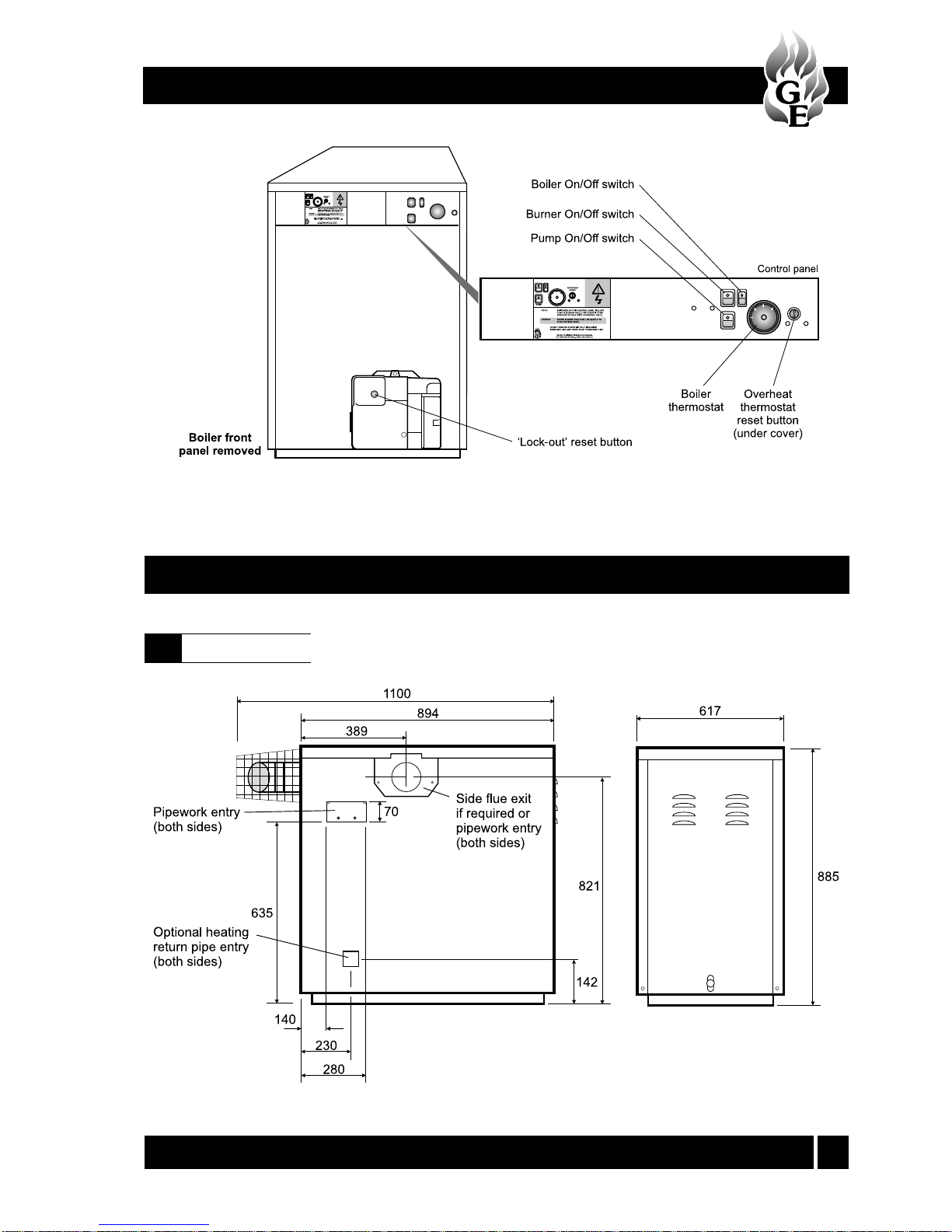
To access the Outdoor module controls, remove the front
panel by turning the handle and withdrawing it forwards
at the bottom.
1 Ensure that - There is sufficient fuel, of the
correct type, in the supply tank and all fuel supply
valves are open. The water supply is on. The
electricity supply to the boiler is off. The boiler
On/Off switch is set to OFF, the pump and burner
switches are set to off (the neons in the switches
are not alight). The room thermostat (if fitted) is at
the desired setting. The boiler thermostat is set to
the required setting.
2 Switch on the electricity supply to the boiler.
3 Set the On/Off switch to ON and the heating timer (if
fitted) to ON. Set the burner and pump switches to ON.
A neon in the switch lights when it is in the on position.
The boiler will now light automatically.
For short periods - Set both the burner and pump
switches to OFF.
To restart, simply set both switches to ON.
For long periods: Set both the burner and pump
switches to OFF. If required, the fuel supply valve may
be closed and the water and electricity supplies turned
off at the mains.
Note: The built in frost thermostat will not operate if
the electricity supply to the boiler is switched off.
1 Check that the boiler On/Off, burner and pump
switches are set to ON.
2 Check that the timer (if fitted) is working and is in an 'on'
period.
3 Check that all thermostats are set to the desired
setting and are calling for heat.
4 Check if the burner 'Lock-out' reset button is lit. If it
is, press it to start the burner. If the burner fails to light
and goes to 'Lock-out' again, check that you have
sufficient fuel in the storage tank and that the fuel
supply valve is open.
5 Ensure that a fuse has not blown or that the
electricity supply has not failed.
6 Check to see if the safety thermostat has operated.
If the burner still fails to light after carrying out these
checks then a fault exists. Switch off the electricity
supply to the boiler and contact your Service engineer.
Lighting your boiler (see Fig. A)
1.2
Turning off your boiler (see Fig. A)
1.3
Points to check if burner fails to light
1.4
Boiler controls (see Fig. A)
1.1
Page 3
3
Combi 90 Outdoor Module
1 - USER INSTRUCTIONS
Fig. A
Fig. 1
Boiler dimensions
2.1
2 - BOILER TECHNICAL INFORMATION
Page 4
Combi 90 Outdoor Module
4
Note: Boilers are despatched for use with kerosene.
Combi 90 Outdoor Module using Class C2 kerosene
2.3
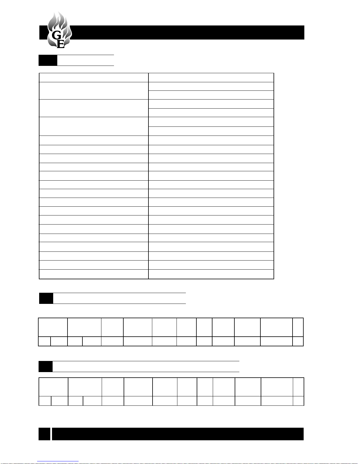
Boiler technical data
2.2
Model
Boiler water content litre
gal
* Weight (dry) kg
lb
Max. heat input (Kerosene) kW
Btu/h
Connections: Heating flow and return
Cold water mains inlet
Domestic hot water outlet
Pressure relief valve discharge
Boiler thermostat range
Limit (safety) thermostat switch off temp.
Maximum heating system pressure (cold)
Minimum heating system pressure (cold)
Pressure relief valve
Expansion vessel
Maximum heating system volume
Maximum operating pressure
Minimum domestic hot water flow rate
Maximum domestic hot water temperature
Maximum mains water inlet pressure
Minimum recommended mains water inlet pressure
Combi 90
40
8.8
202
445
27.6
94 200
Flow - 22 mm copper pipe, Return - 1" BSP
15 mm copper pipe
15 mm copper pipe
15 mm copper pipe
75 to 85°C
111°C ± 3°C
1.0 bar
0.5 bar
2.5 bar
12 litres (pre-charged at 1.0 bar)
90 litres (approximately)
2.5 bar
3.0 litres/min (0.66 gal/min)
65°C
8.0 bar
2.5 bar
2 - BOILER TECHNICAL INFORMATION
Combi 90 Outdoor Module using Class D gas oil - Conventional flue only
2.4
Flue gas mass
flow rate (kg/h)
38.7
CO
2
(%)
12.0
(kW)
26.4
(Btu/h)
90 000
Heat Output
(kW)
27.9
(Btu/h)
95 250
Net Heat Input
Net eff. **
(%)
94.6
Head
type
LD3
Nozzle
size
0.60/60°S
Oil press.
(bar)
12.0
Smoke
No.
0 - 1
Fuel flow
rate (kg/h)
1.97
Net flue gas
temp. (°C)
200
Flue gas mass
flow rate (kg/h)
38.7
CO
2
(%)
12.0
(kW)
26.4
(Btu/h)
90 000
Heat Output
(kW)
27.6
(Btu/h)
94 200
Net Heat Input
Net eff. **
(%)
95.8
Head
type
LD3
Nozzle
size
0.75/60°EH
Oil press.
(bar)
9.5
Smoke
No.
0 - 1
Fuel flow
rate (kg/h)
2.40
Net flue gas
temp. (°C)
180
Page 5
5
Combi 90 Outdoor Module
Note: The burner is supplied factory set at the output given in Section 2.3.
When commissioning, the air damper must be adjusted to obtain the correct CO2.
Air damper settings
2.5
2 - BOILER TECHNICAL INFORMATION
Fig. 2
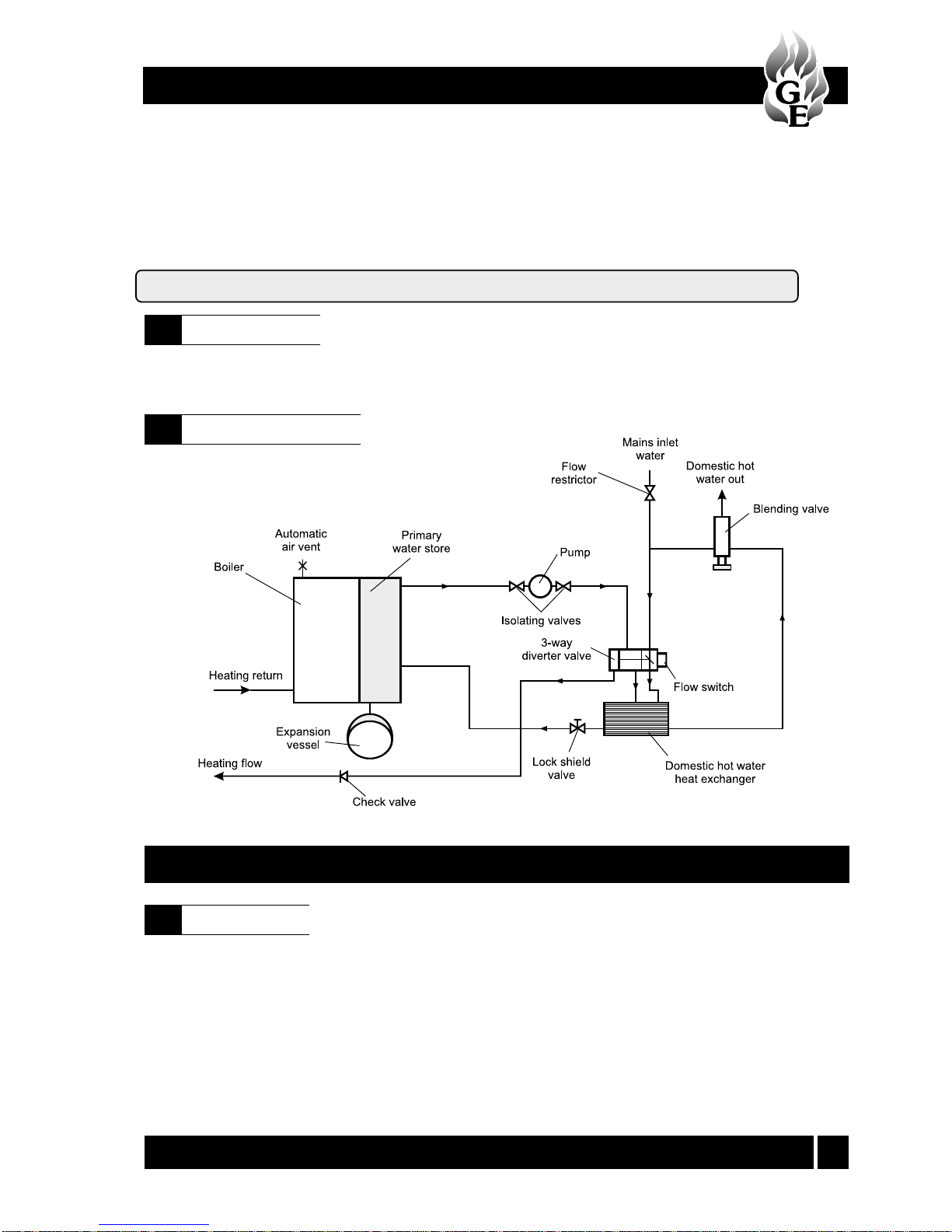
Water schematic of boiler
2.6
3 - GENERAL BOILER INFORMATION
Boiler description
3.1
The Grant Outdoor Combination boiler has been
designed for use with a sealed central heating system
and will provide domestic hot water at mains pressure.
The boiler is supplied with the burner fitted and is
suitable for use with kerosene only when used with the
factory fitted low level discharge flue system. The flue
can be adjusted on site for either rear, left hand or
right hand flue outlet position, as required.
A Conventional external stainless steel flue system is
available for use with kerosene or gas oil.
The temperature of the water leaving the boiler to heat
the radiators may be adjusted using the control
thermostat. It is recommended however, that the
thermostat is set to maximum to achieve optimum hot
water performance. The temperature of the domestic
hot water is controlled by a thermostatic mixing valve
located in the insulated rear compartment of the boiler
casing. Please also refer to Sections 3.5 and 3.6.
Notes:
1 The data given above is approximate only.
2 The above settings may have to be adjusted on site for the correct operation of the burner.
3 Gas Oil is not suitable for use with the low level discharge of the Outdoor modules.
4 Net flue gas temperatures given are ± 10%.
5 ** Net thermal efficiency (BSRIA).
To obtain the correct CO2 level, the final flue gas reading must be taken with all casing and door panels fitted.
Page 6
Combi 90 Outdoor Module
6
3 - GENERAL BOILER INFORMATION
The Outdoor Module is supplied in one pack, with the
burner and control panel factory fitted. The flue
terminal and wire guard are supplied loose (inside the
carton) for fitting on site.
Installation of a Combi boiler must be in accordance
with the following recommendations:-
a Building Regulations for England and Wales,
and the Building Standards for Scotland issued
by the Department of the Environment and any
local Byelaws etc.
b Model and local Water Undertaking Byelaws.
c Applicable Control of Pollution Regulations.
d The following OFTEC requirements:-
OFS T100 Polythene oil storage tanks for
distillate fuels.
OFS T200 Fuel oil storage tanks and tank
bunds for use with distillate fuels,
lubrication oils and waste oils.
Further information may be obtained from the
OFTEC Technical Information Book 3
(Installation requirements for oil fired boilers
and oil storage tanks).
The installation should also be in accordance with the
latest edition of the following British Standard Codes
of Practice:-
BS 715 Metal flue pipes, fittings, terminals
and accessories.
BS 799:5 Oil storage tanks.
BS 1181 Clay flue linings and flue terminals.
BS 4543:3 Factory made insulated chimneys for
oil fired appliances.
BS 4876 Performance requirements for oil
burning appliances.
BS 5410:1 Code of Practice for oil firing appliances.
BS 5449 Forced circulation hot water systems.
BS 7593 Code of Practice for treatment of
water in heating systems.
BS 7671 Requirements for electrical
installations, IEE Wiring Regulations.
Failure to install and commission appliances
correctly may invalidate the boiler warranty.
3.4
Fuel supply
Regulations to comply with
3.3
3.5
Method of operation
Delivery
3.2
For details of the fuel supply, refer to Section 3.4 in
the main Installation and Servicing instructions
supplied with the boiler.
Once the boiler is switched on it will always provide
domestic hot water upon demand. The timer only
controls the operating times of the central heating.
When central heating is not required, the timer switch
should be set to OFF.
Domestic hot water supply always takes priority over
central heating. If a demand for hot water occurs
during a period of central heating, the boiler mode will
automatically change to provide hot water until the
demand ceases. This interruption in the central heating
only lasts for as long as hot water is required and
should not be noticed by the User.
Central Heating Mode - If there is a call for heat, i.e. the
timer and room thermostat (if fitted) are calling for heat,
the pump will start to circulate the central heating water
and the burner will light. When the temperature in the
boiler reaches that set on the boiler thermostat, the burner
is turned off. The pump continues to run, circulating
water around the system, for as long as both the timer and
room thermostat (if fitted) are calling for heat. As the
heating system water cools, the temperature drop is
detected by the boiler thermostat and the burner is
automatically restarted for the cycle to continue until
either the timer or room thermostat stops calling for heat.
The burner and pump are then turned off.
Domestic Hot Water Mode - When a demand for hot
water (by opening a hot tap, etc.) is sensed by the diverter
valve flow switches, the pump starts and the water in the
boiler is diverted through the domestic hot water heat
exchanger, heating the incoming mains water. The hot
water produced is mixed in the thermostatic blending
valve with incoming mains water to automatically ensure
that the temperature does not exceed 65°C.
Note: For optimum performance it is recommended that
the thermostatic blending valve is set to provide a hot
water temperature at the outlets between 45 and 50°C.
Note: If the water in the boiler is already up to
temperature, there will be a delay before the burner
starts to maintain the water temperature in the boiler.
Page 7
7
Combi 90 Outdoor Module
When the hot tap is closed and the diverter valve flow
switches sense that hot water is no longer required, if the
remote timer is set to either TIMED or CONSTANT, the
boiler will return to the central heating mode, with the
pump and burner running. If the timer is not calling for
central heating, the pump is turned off but the burner will
continue to run for a short period until the water in the
boiler reaches the required temperature ready for another
hot water operation.
1 A hot water flow rate of up to 17 litres/min is
available, dependant on mains water pressure. To
maintain a longer and more consistent hot water
temperature, a flow restrictor is factory fitted to
limit the flow rate to approximately 15 litres/min.
The flow restrictor is located in the outlet side of
the cold water inlet isolating valve.
2 The incoming mains water pressure should be
between 1 and 8 bar to ensure efficient operation.
If the pressure is above 8 bar a pressure reducing
valve must be fitted.
The boiler may still operate down to a pressure of
1.0 bar but with a reduced flow rate. Below 1.0 bar
the hot water flow switch will turn the boiler off.
The minimum flow rate needed for the flowswitch
to operate is 3 litres/min.
3 To ensure economic use, the pipe runs between the
boiler and hot taps should be in 15 mm copper pipe
and be as short as possible. Where possible the
pipework should be insulated to reduce heat loss.
4 All taps and mixing valves used in the domestic hot
water system must be suitable for operating at a
mains pressure of up to 8 bar.
5 If required, a shower may be fitted in the domestic hot
water system. It is recommended that thermostatically
controlled shower valves are used to protect against a
flow of water at too high a temperature. If a fixed
head type shower is used, no anti-syphonage devices
are required. If a loose or flexible head type shower is
used, it must be arranged so that the head cannot fall
closer than 25 mm above the top of the bath, thereby
preventing immersion in the bath water. If this is not
practicable, an anti-syphonage device must be fitted
at the point of the flexible hose connection.
6 The supply of hot and cold mains water direct to a
bidet is allowed (subject to local Water Undertaking
requirements) provided that the bidet is of the overrim flushing type. The outlets should be shrouded and
unable to have a temporary hand held spray attached.
Arrangements for anti-syphonage are not necessary.
3 - GENERAL BOILER INFORMATION
7 Before the mains water supply pipe is connected to the
boiler, it should be thoroughly flushed out to avoid the
danger of dirt or foreign matter entering the boiler.
8 The mains water connection to the boiler must be
the first connection from the mains supply.
Note: Hard Water - A water hardness test kit is supplied
with the boiler. Should the total hardness of the water
supply exceed 125 ppm, an in-line scale inhibitor or
water softener (both available from Grant UK) should
be fitted in the cold water supply to the boiler. Consult
the local Water Undertaking if in doubt.
Important: Do not immerse the test strip in running
water and avoid contact.
Fill a clean container with a sample of water from the
mains cold water supply to the boiler.
Immerse the test strip in the water for approximately one
second, ensuring that all the test zones are fully wetted.
Shake off the surplus water and wait for one minute.
Assess the colouration of the test zones using the
following chart.
Domestic hot water system
3.6
To use the water hardness kit
3.7
Green areas
4
3
2
1
0
Violet areas
0
1
2
3
4
Hardness
very soft
soft
medium
hard
very hard
Total hardness mg/l (ppm)
<50 mg/l calcium carbonate
>70 mg/l calcium carbonate
>125 mg/l calcium carbonate
>250 mg/l calcium carbonate
>370 mg/l calcium carbonate
Note: (1 mg/l = 1 ppm (part per million)
If the hardness reading is found to be in the medium to
very hard range (the shaded area), it is essential that some
form of water conditioner or softener is fitted to reduce
scale formation within the combination boiler. Failure to
do so may invalidate both the manufacturers warranty
and any extended warranty covering the appliance.
The water conditioner or softener should be fitted to
the cold water supply serving the appliance and in
accordance with the manufacturers instructions. Grant
Engineering (UK) Ltd. cannot be held responsible for
any damage or misuse caused by the fitting of any
water conditioning device.
Please protect the domestic hot water system from
the harmful effects of scale.
Page 8
Combi 90 Outdoor Module
8
3 - GENERAL BOILER INFORMATION
1 Outdoor Modules are supplied with a factory fitted
frost protection thermostat, located inside the
boiler control panel. This is pre-wired to the boiler
electrical system and is factory set to 5°C.
2 For total system protection against freezing,
particularly during extended periods without
electrical power, Grant recommend the use of a
combined heating system anti-freeze and corrosion
inhibitor, used in accordance with the
manufacturers instructions.
1 The boiler must stand on a solid, level surface capable
of supporting the weight of the boiler when full of
water, e.g. a prepared concrete standing, paving slabs
bedded down on sand/cement, or similar.
2 The Module can be installed either against the
building or free standing some distance away from
the building.
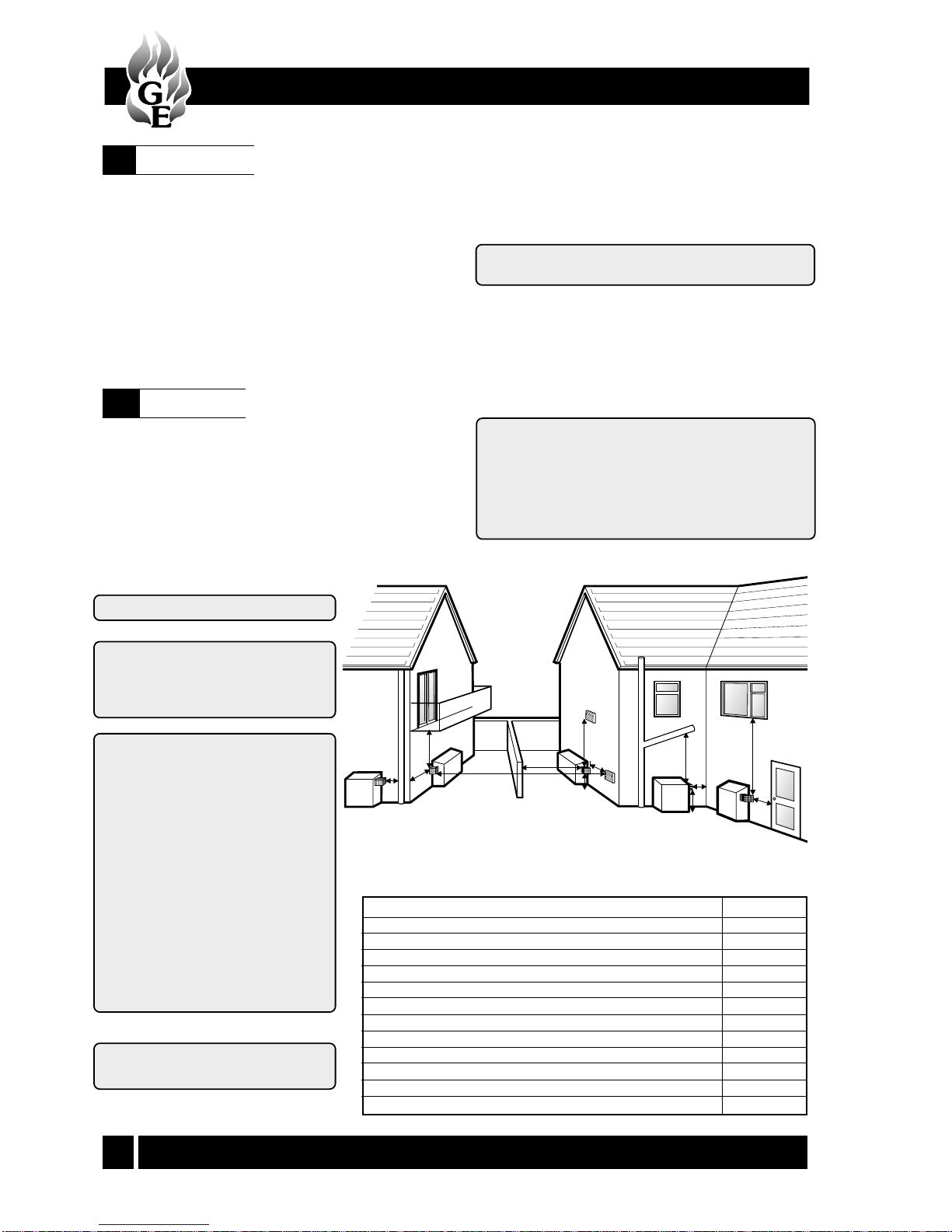
3 The Module must be positioned such that the
required clearances from the low level flue outlet,
as shown in Fig. 3, are achieved.
Note: The flue outlet can be fitted to either the left,
right or rear of the Module, as required.
4 Adequate clearance must be left around the
Module for servicing. In particular, a minimum
clearance of 600 mm above the Module for
removal of the top panel, 600 mm at the opposite
end to the flue outlet for access to the burner and
600 mm at the flue outlet end for access to the
circulating pump and Combi boiler components.
5 The flue terminal must be a minimum distance of
1.8 m from an oil storage tank.
The flue terminal should be positioned so as to
avoid products of combustion accumulating in
stagnant pockets around the building or entering
into buildings.
Frost protection
3.8
Boiler location
3.9
Fig. 3 - Flue terminal positions
K
D
F
AJ
B
L
G
C
C
I
H
E
A Below gutters, eaves or balconies (with protection)
B Horizontally from a door, window or air vent
C Above ground, flat roof or balcony level
D Below gutters, eaves or balconies (without protection)
E From an external corner
F From a terminal facing the terminal
G From a surface facing the terminal
H Vertically from a terminal on the same wall
I Horizontally from a terminal on the same wall
J Directly below an opening, air brick, window, etc.
K From a vertical drain pipe or soil pipe
L From an internal corner
*600
600
**300
*600
300
1200
600
1500
750
600
300
300
Terminal position Min. distance
Distances measured to rim of terminal.
Clearances recommended by Grant
Engineering (UK) Limited in
accordance with British Standards
and Building Regulations.
Notes:1 An opening means an
openable element, such as an
openable window, or a
permanent opening such as a
permanently open air vent.
2 Notwithstanding the
dimensions given, a terminal
should be at least 300 mm
from combustible material,
e.g. a window frame.
3 A way of providing
protection of combustible
material would be to fit a
heat shield at least 750 mm
wide.
Notes: * 75 mm with protection.
** 300 mm British Standards.
Page 9
9
Combi 90 Outdoor Module
3 - GENERAL BOILER INFORMATION
General - Grant boilers are compatible with both
copper and plastic pipe. Where plastic pipe is used it
must be of an oxygen barrier type. The first metre of
pipe connected to the boiler must be made in copper.
Sealed systems - Where a sealed heating system is
fitted to the boiler only copper tube may be used.
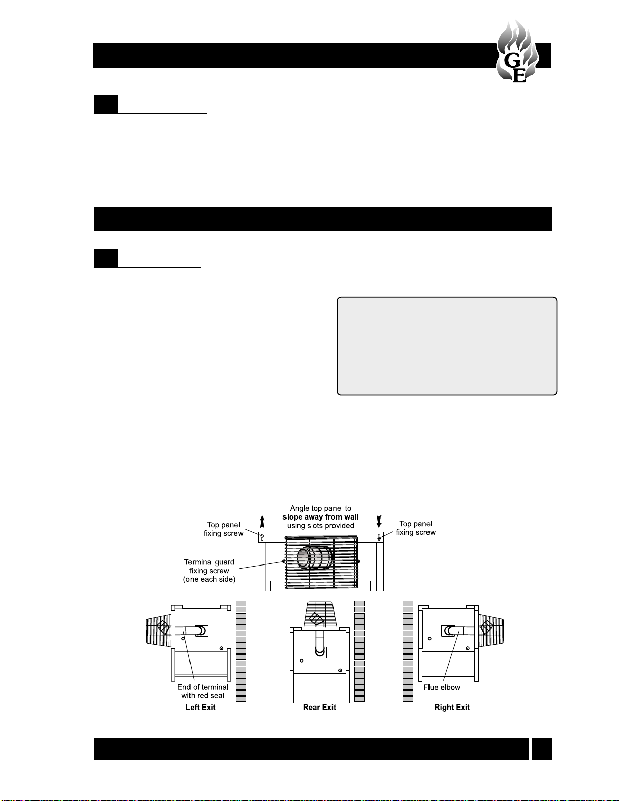
1 Carefully remove the packaging from the boiler
and lift it off the pallet.
2 The flue terminal guard is supplied loose inside the
packaging.
3 Remove the case top panel (four screws).
4 The flue may exit the casing from the left, right or rear
of the casing. The casing has two removable blanking
panels and a flue exit panel. Fit the panel with the flue
exit hole and seal in the required position.
5 Slacken the wing nuts holding the flue elbow and
rotate the elbow to the required direction for the
flue to exit the casing.
6 Push the end of the flue terminal section with the
red seal through the seal in the casing. The terminal
has been factory lubricated. Take care not to
dislodge or damage the red seals.
Fig. 4
Unpack the boiler
4.1
Pipework materials
3.10
4 - BOILER INSTALLATION
Underfloor systems - Plastic pipe may be used on
underfloor systems where the plastic pipe is fitted after
the thermostatic mixing valve. Copper tube must be
used for the primary pipework between the boiler and
the underfloor mixing/blending valves.
7 Carefully insert the terminal into the flue elbow until
the bend of the terminal contacts the outer casing,
then, pull the terminal forward approximately 25 mm
and rotate the bend so that the outlet is horizontal.
Rear Exit - The flue must discharge away from the
building.
Side Exit - The flue should discharge towards the
rear of the casing to prevent flue gases re-entering
the boiler casing through the air inlet vents on the
casing front door.
The flue terminal must be fitted horizontally to
prevent dripping from the end of the terminal.
8 Tighten the wing nuts holding the flue elbow and fit the
stainless steel flue guard using the two screws provided.
9 The top panel of the casing has been designed so that
it may be fitted to create a slight slope away from the
side positioned against the wall. To tilt the top panel,
loosen the four top panel casing screws, one at each
corner and push down on the side furthest from the
wall. Tighten the screws. See Fig. 4.
Page 10
Combi 90 Outdoor Module
10
4 - BOILER INSTALLATION
1 If the boiler is to be fitted against the wall, prepare the
wall to accept the heating system pipework. To mark
the wall for drilling, refer to Fig. 1 for the positions of
the pipework openings in the enclosure sides.
Note: Pipework should be insulated where it
passes through the wall into the boiler enclosure.
2 The electrical supply to the boiler should be
routed through the wall in a suitable conduit,
such that it enters the boiler enclosure via one of
the pipework openings. The cable can be routed
to the front of the boiler, for connection to the
boiler control panel, either over the top or
beneath the boiler heat exchanger. Heat resistant
PVC cable, of at least 1.0 mm² cross section
should be used within the boiler enclosure.
3 The oil supply line should be installed up to the
position of the boiler. Refer to the main installation
and servicing manual for details. The final connection
into the boiler enclosure can be made with 10 mm soft
copper, routed along the base of the enclosure (either
between the enclosure and wall or in front of the
enclosure) to enter through one of the holes located in
the bottom edge of either side panel, at the front
(burner) end.
4 A remote sensing fire valve must be installed in the
fuel supply line a minimum of 1 metre from the point
of entry to the boiler, with the sensing head located
above the burner using the clip mounted on the
underside of the control panel.
Preparations for installation
4.2
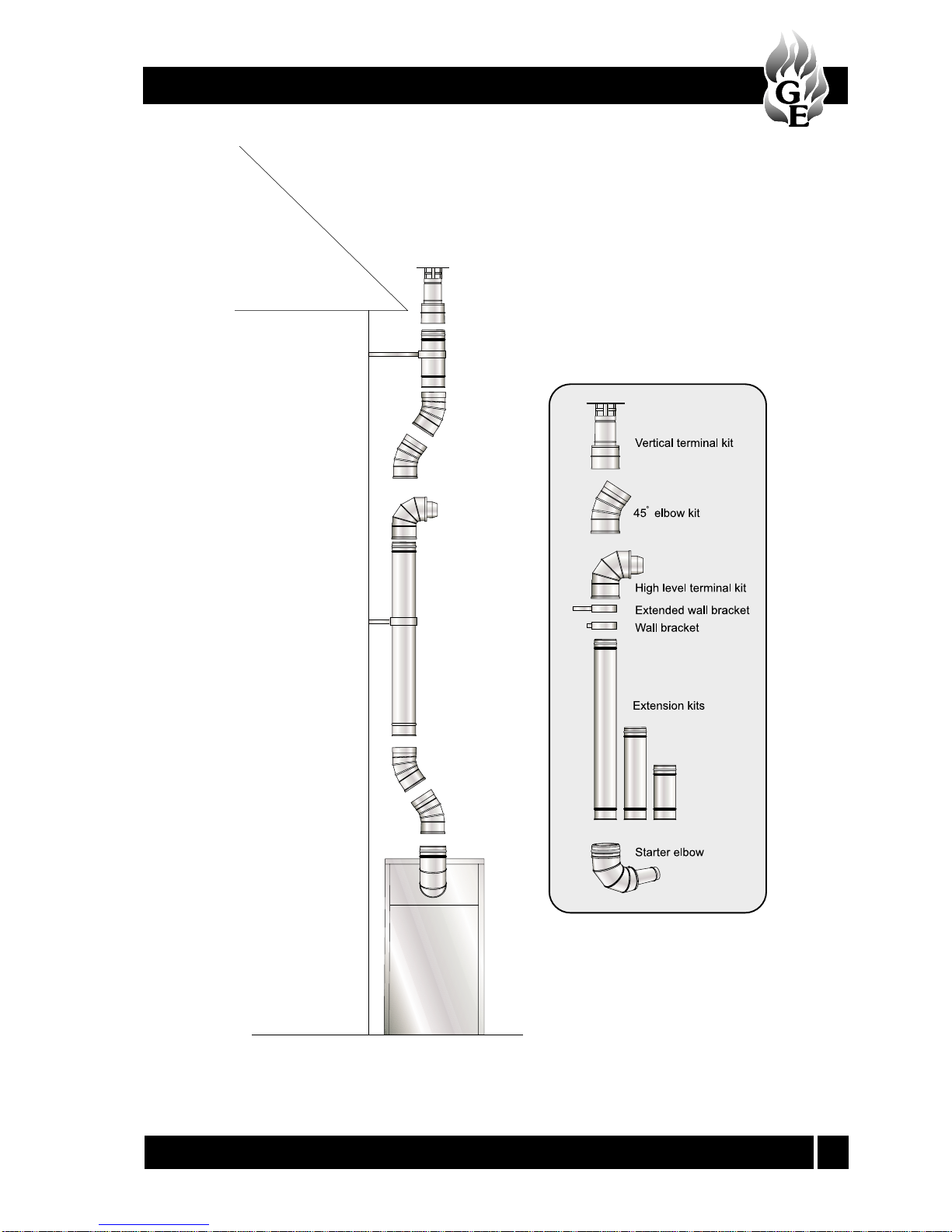
Conventional flue
4.3
Where it is not practical to use the factory supplied
low level flue, the Grant range of Outdoor Modules
may be fitted with a conventional flue system.
A twin wall stainless steel insulated flue system is
available from Grant UK.
An insulated boiler connector elbow, complete with
test point, replaces the low level terminal and flue
guard supplied with the boiler.
The Grant External flue system connects to the elbow
and may terminate at high level or vertically as
required. See Fig. 5.
The flue system is suitable for use with class C2
kerosene and class D gas oil.
When using gas oil the flue must terminate a
minimum of 2 metres above outside ground level.
The following components are available from Grant UK.
Item
Starter elbow
150 mm extension
250 mm extension
450 mm extension
950 mm extension
195-270 mm adjustable extension
45° elbow
High level terminal
Vertical terminal
wall bracket
Extended wall bracket kit
Part No.
GKM90
GX150/90
GX250/90
GX450/90
GX950/90
GXA250/90
GE45/90
GTH90
GTV90
GWB90
GEB90
Page 11
11
Combi 90 Outdoor Module
4 - BOILER INSTALLATION
Fig. 5
Page 12
Combi 90 Outdoor Module
12
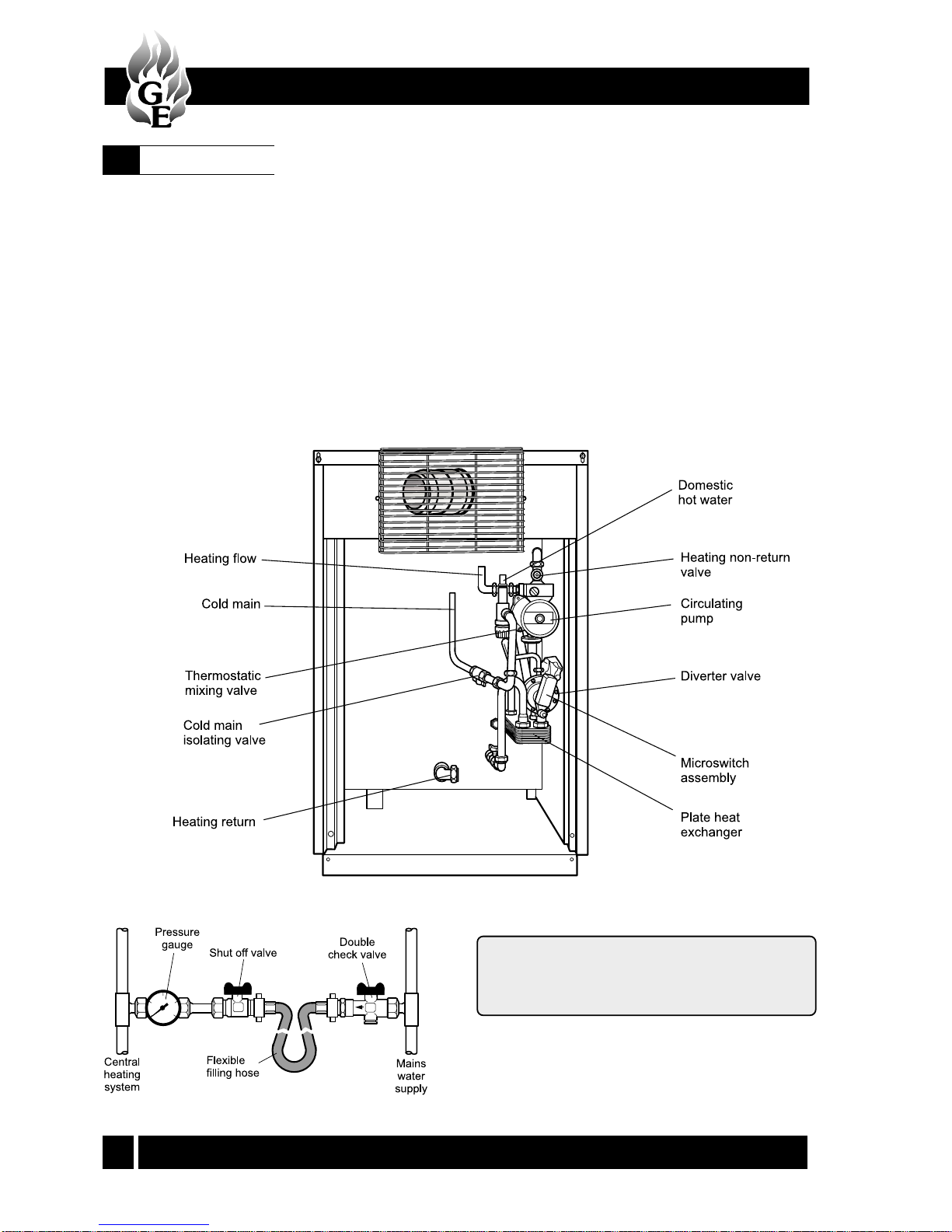
Fig. 6
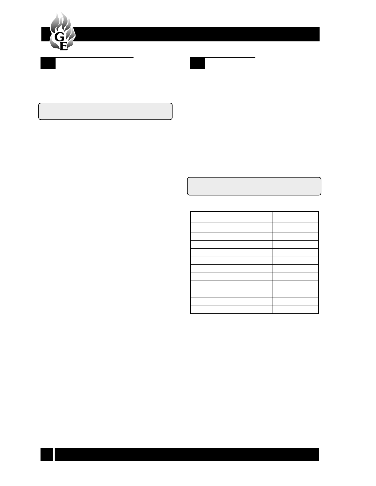
1 The pipework connections are housed within an
insulated compartment inside the rear end of the
boiler casing (opposite end from the burner). These
connections are accessed by removing the back panel
of the enclosure.
2 The boiler side panels are fitted with movable plates
to allow the pipework to exit the boiler enclosure. The
side flue exit holes in the side panels may also be
used to route the pipework and cables into the
building. Where the boiler is sited remotely from the
building, the pipework can be routed through the
holes in the base of the rear compartment.
Water connections
4.4
6 The filling loop kit and pressure gauge supplied,
should be located in a convenient and easily
accessible position inside the house, where the gauge
will be visible to the User (see Fig. 7).
Fit the double check valve to the mains water supply,
ensuring correct flow direction as indicated by the
arrow on the valve. Fit the pressure gauge and shutoff valve to the central heating system. Fit the flexible
filling hose between the two valves.
Fig. 7
4 - BOILER INSTALLATION
3 The cold mains and domestic hot water connections are
supplied with 15 mm Tectite elbows which can be turned
to allow either left or right hand pipe entry. It is
recommended that an isolating valve be fitted on the
cold mains supply pipe at a point where the supply leaves
the building and before it enters the Module casing.
4 The heating flow should be fitted with the 22 mm
Tectite elbow supplied to allow either left or right
hand pipe entry.
5 The boiler is fitted with a 1" BSP heating return tapping
mounted centrally at low level on the rear of the water
jacket. A 1" BSP x 22 mm bent coupling is supplied.
Page 13
13
Combi 90 Outdoor Module
4 - BOILER INSTALLATION
The expansion vessel fitted is supplied with a
charge pressure of 1.0 bar (equivalent to a max.
static head of 10.2 metres). The charge pressure
must not be less than the actual static head at the
point of connection. Do not pressurise the vessel
above 1.5 bar.
The air pressure in the vessel must be checked anually.
The central heating system volume, using the expansion
vessel as supplied, must not exceed 90 litres. If the
system volume is greater, an extra expansion vessel
(complying with BS 4841) must be fitted as close as
possible to the central heating return connection on the
boiler. The charge pressure of the extra vessel must be
the same as the vessel fitted in the boiler.
Refer to BS 7074:1 for further guidance.
The air charge pressure may be checked using a tyre
pressure guage on the expansion vessel Schraeder
valve. The vessel may be re-pressurised using a
suitable pump. When checking the air pressure the
water in the heating system must be cold and the
system pressure reduced to zero.
A simple test to check if the expansion vessel size is
adequate, is to fully heat the system and if the pressure
rises no more than 2.0 bar the vessel is adequate. A
higher figure indicates that an extra vessel is required.
1 Undo the two screws from the left hand cover on
the control panel to gain access to the boiler wiring
terminal block.
2 Pass the mains power supply cable through the
cable grommet into the control panel, through the
cable clamp and connect to the 12-way terminal
block as follows:-
Permanent Live (brown) to terminal 3 - marked L3
Neutral (blue) to terminal 4 - marked N4
Earth (green/yellow) to terminal 5 - marked E5
3 To control the central heating On/Off periods, it is
recommended that the boiler be wired to a single
channel timer or (programmable) room thermostat
sited at a convenient location within the property.
The switched live from the central heating control
system must be connected to terminal 1 on the 12-
way terminal block - marked S/L.
Note: When connected in this way, a link must be
added between terminals 2 and 3 - marked S/L2
and L3 to enable the burner to fire.
4 Alternatively, a two channel programmer may be
fitted to the boiler as follows:Switched Live Heating to terminal 1 - marked S/L1
Switched Live Hot Water to terminal 2 - marked S/L2
Permanent Live Frost stat to terminal 3 - marked L3
Mains Neutral to terminal 4 - marked N4
Mains Earth to terminal 5 - marked E5
The programmer should be of an internally
linked type.
Note: If connected in this way, the User must be
made aware that if the hot water channel is left in
the off position, hot water may not be available
upon demand and that the primary store may need
to recover before any hot water is available.
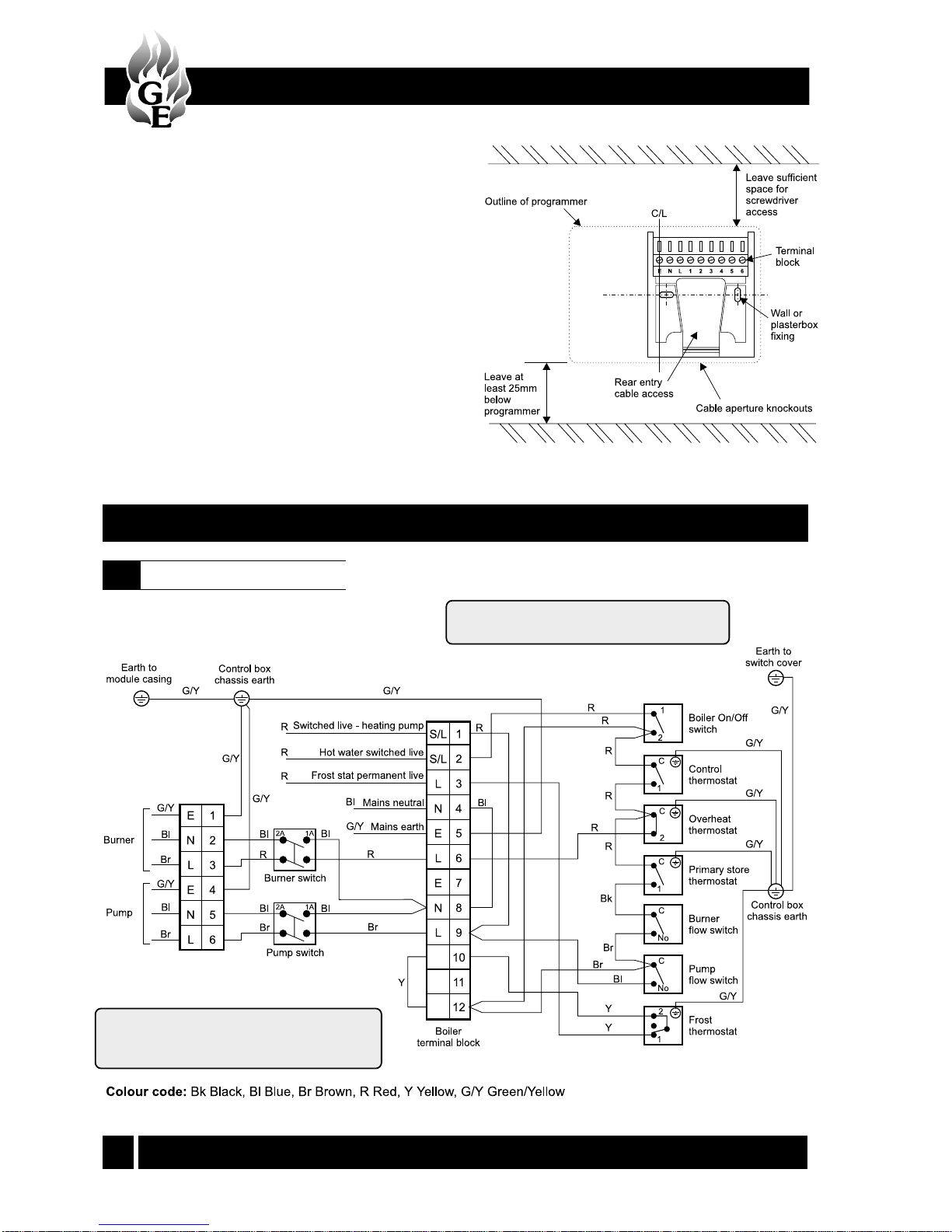
1 Select the desired fixing position for the heating
controller.
2 When fixing the wallplate remember the
connections are at the top and the vertical centre
line of the unit is at the position shown (C/L) - in
line with the terminal E. See Fig. 8.
3 Fix the wallplate to the wall or flush mounted box
as required.
4 Surface cables can only enter from below the unit. If
mounted on a flush mounted box, cables can enter
from the rear through the aperture in the wallplate.
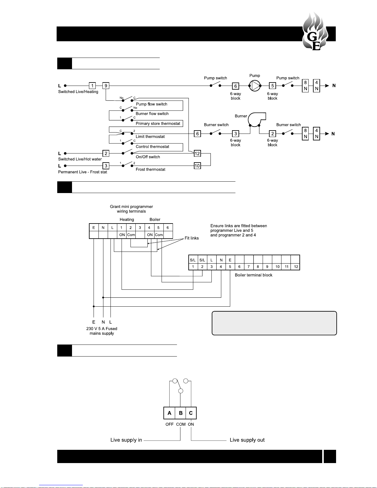
5 Important: Links must be fitted between terminal
L and 5 and between 2 and 4. See wiring diagram
in Section 5.3.
6 Whilst the unit does not require an Earth
connection, a terminal is provided on the wallplate
for Earth continuity purposes.
7 Ensure that all dust and debris are cleared from the area.
8 Locate the module on the latches at the bottom of
the wallplate and hinge upwards to fully engage the
unit connectors into the wallplate. Tighten the two
fixing screws to secure the unit to the wallplate.
9 Before setting the programme, the unit and circuit
should be checked. Switch ON the mains electricity
supply and set the left hand rocker switch to
'CONSTANT' and the right hand rocker switch to
'ON'. Adjust any remote thermostats to check that
the services operate correctly.
Expansion vessel pressure
4.5
Connect the power supply
4.6
Connection of Grant Mini-Programmer
4.7
Page 14
Combi 90 Outdoor Module
14
Fig. 8
5 - WIRING DIAGRAMS
4 - BOILER INSTALLATION
Control panel wiring diagram
5.1
Refer to Notes in Section 4.6.
Note: If a single channel timer is used, a link
must be fitted between terminals 2 and 3.
If a room thermostat is fitted, it must be wired
in series with the time control and the boiler
terminal S/L 1.
10 Set the left hand rocker switch to 'OFF', check that
the heating goes off and that the hot water
operation stays on.
11 Set the right hand rocker switch to 'OFF' and check
that both services do not operate.
12 Finally, return the left rocker switch to 'TIMED' and
the right hand rocker switch to the 'ON' position.
Page 15
15
Combi 90 Outdoor Module
5 - WIRING DIAGRAMS
Functional flow wiring diagram
5.2
Connection of Grant remote wall mounted mini programmer
5.3
Refer to Notes in Section 4.7.
If an in series room thermostat is fitted, it must be
wired between terminal 1 on the Grant Mini
Programmer and the boiler terminal S/L 1.
Grant programmable room thermostat
5.4
A programmable room thermostat - Part No. RSKIT is available from Grant UK. The thermostat has a 5/2 day
operation and enables six time and temperature changes each day. The thermostat incorporates frost protection and an
On/Off facility.
Page 16
Combi 90 Outdoor Module
16
6 - COMMISSIONING
Refer to Fig. A, page 3, for boiler controls
It is important that the following commissioning
procedure is carried out to ensure safe and efficient
operation of the boiler.
Note: Check that the baffles are in position and
that the cleaning cover is correctly fitted and a
good seal made.
1 Check that the water system has been vented and
pressurised, and there are no leaks.
2 Check that all fuel line valves are open.
3 Remove the boiler casing front panel and the
plastic burner cover (two screws) if they were not
previously removed.
4 Connect a combined vent manifold and pressure
gauge to the pressure gauge connection port on the oil
pump. Open the vent screw on your vent manifold to
vent the supply while the pump is running.
5 Set the boiler On/Off switch to 'OFF'. Check that
all system controls are calling for heat and turn the
boiler thermostat to maximum. Switch on the
electricity supply.
6 Fully open a hot tap and allow it to run to vent the
internal primary circuit. Set the boiler, burner and
pump On/Off switches to 'ON'. The boiler will
operate and the burner should light within about 10
seconds. If the burner does not light and the 'Lock-
out' reset button lights, wait for about 45 seconds
then press the reset button to restart the ignition
process. This procedure may have to be repeated
several times during first lighting.
7 Set the timer switch to 'CONSTANT' and close the
hot tap, the boiler will now be operating in the
central heating mode.
8 With the burner alight, check the fuel pressure.
Refer to the Technical Information, see section 2.3
or 2.4. Adjust the pressure if necessary.
9 Operate the boiler until it reaches normal operating
temperature. Check oil supply/return pipe for leaks,
rectifying where necessary.
10 With the burner alight, re-check the fuel pressure and
re-adjust if necessary. Switch the boiler off, remove
the pressure gauge and replace the plug in the pump.
11 Having ensured that there are no oil leaks, replace
the burner cover.
12 Relight the boiler and allow it to run for 20 minutes
then check the following:CO2 level, Flue gas temperature and Smoke Number.
Refer to the Technical Information in Section 2.3 or
2.4. A test point is provided in the flue deflector.
13 Check the smoke number, if satisfactory check the
CO2. Adjust the burner air regulator. Turning the
screw anticlockwise closes the damper and
increases CO2 level, turning the screw clockwise
opens the damper and reduces CO2 level.
Re-check the smoke number if the air damper has
been moved.
Under no circumstances must the smoke number be
above 1.
A suitable position for the air damper is one which
gives 1% less CO2 than that which has a smoke
number of 1.
Note: To obtain the correct CO2 level, the final
flue gas reading must be taken with all casing
and door panels fitted.
Note: It is important that the air damper is
correctly set.
14 Check the flue gas temperature.
15 Check the boiler overheat thermostat by removing
the boiler thermostat phial (the shorter one) from
the pocket in the back of the boiler, just to the left
above the pump. The boiler should switch off on the
overheat thermostat. Replace the phial. Unscrew
and remove the plastic cap covering the reset
button, press the reset button and replace the cap.
16 When the boiler has been adjusted and is running
satisfactorily, balance the central heating system by
adjusting the radiator lock shield valves. Start with
the radiator nearest the boiler and adjust the valves
to achieve the required temperature drop across
each radiator. If thermostatic radiator valves have
been installed, check the system by-pass.
17 Switch off the boiler.
18 With the system hot, check again for leaks, rectifying
where necessary. Drain the heating system while it is
hot to complete the flushing process.
19 Refill, vent and pressurise the system as described in
main installation and servicing instructions, adding a
suitable inhibitor. For further information concerning
inhibitors contact Grant Engineering (UK) Limited.
Page 17

17
Combi 90 Outdoor Module
6 - COMMISSIONING
20 Replace the casing panels, if not already fitted.
Note: After commissioning the boiler you should
complete the Commissioning Report on page 2 of
main instructions supplied with the boiler.
If the boiler is to be left in service with the User, set
the controls, timer (see User's Operating manual) and
room thermostat (if fitted) to the User's requirements.
If the boiler is not to be handed over immediately,
close the boiler fuel supply valve and switch off the
electricity supply.
If there is any possibility of the boiler being left during frost
conditions, then the boiler and system should be drained.
For details of servicing and Replacement of components,
Fault finding refer to the main instruction manual.
7 - INFORMATION FOR THE USER
The User must be advised (and demonstrated if
necessary) of the following important points:-
1 How to light and turn off the boiler and how to
operate the system controls.
2 The precautions necessary to prevent damage to
the central heating system and to the building, in
the event of the boiler not being in operation
during frost conditions.
3 The importance of servicing the boiler to ensure
safe and efficient operation. This should normally
only be required once a year.
4 The type of fuel used.
5 That any servicing or replacement of parts must
only be carried out by a suitably qualified engineer.
6 Ensure that the boiler controls and room thermostat
(if fitted) are set to the User's requirements.
7 Tell the user the system pressure and show them
the position of the safety valve discharge pipe.
8 Show the User how to reset the overheat thermostat
and how to restart the boiler if it goes to 'Lock-out'.
Leave these instructions and the main instruction
manual with the User.
Page 18

Combi 90 Outdoor Module
18
Page 19

19
Combi 90 Outdoor Module
Page 20
Complies with the EC Low voltage,
Electromagnetic compatibility and
Boiler efficiency Directives
89/336/EEC
73/23/EEC
92/42/EEC
D124
SUPPLEMENT
Grant Engineering (UK) Limited
Hopton House, Hopton Industrial Estate, Devizes, Wiltshire SN10 2EU
Telephone: (0870) 7775553 Fax: (0870) 7775559
email: [email protected] website: www.grantuk.com
This manual is accurate at the date of printing but will be superseded and should be
disregarded if specifications and/or appearances are changed in the interests of continued
product improvement.
All goods sold are subject to our official Conditions of Sale, a copy of which may be
obtained on application.
© Grant Engineering (UK) Limited 2004. No part of this manual may be reproduced by
any means without prior written consent.
Manual compiled and designed by Publications 2000 Tel: (01670) 356211
SEDBUK Rating:-
Combi 90 Outdoor Module ................... 82.9%
 Loading...