

Grant VortexAir, Aerona3, VortexBlue, VTXBFAIR, HPIDAIR2 Installation And Servicing Instructions
...
Grant VortexAir
VortexBlue Oil Boiler and Aerona³ Air Source
Heat Pump Hybrid
Installation and Servicing Instructions
THESE INSTRUCTIONS SHOULD BE READ IN
CONJUNCTION WITH THE INSTALLATION AND SERVICING
INSTRUCTIONS SUPPLIED WITH THE HEAT PUMP.
UK | DOC 0110 | Rev 1.0 | November 2016

Special Text Formats
The following special text formats are used in this manual for the
purposes listed below:
!
Warning of possible human injury as a consequence of not following the instructions in the warning.
!
Caution concerning likely damage to equipment or tools as a
consequence of not following the instructions in the caution.
!
Used for emphasis or information not directly concerned with
the surrounding tex t but of impor tance to the reader.
WARNING
CAUTION
NOTE
GRANT ENGINEERING (UK) LIMITED
Hopton House, Hopton Industrial Estate, Devizes, Wiltshire, SN10 2EU
Tel: +44 (0)1380 736920 Fax: +44 (0)1380 736991
Email: info@grantuk.com www.grantuk.com
This manual is accurate at the date of printing but will be superseded and should be disregarded if specifications and/or appearances
are changed in the interests of continued product improvement. However, no responsibility of any kind for any injury, death, loss, damage
or delay however caused resulting from the use of this manual can be accepted by Grant Engineering (UK) Limited, the author or others
involved in its publication.
All good sold are subject to our official Conditions of Sale, a copy of which may be obtained on application.
© Grant Engineering (UK) Limited 2016. No part of this manual may be reproduced by any means without prior written consent.

Contents
1 Introduction 4
1.1 General 4
1.2 Outputs 4
1.3 Planning Permission 4
1.4 DNO Application 4
1.5 Servicing 4
1.6 Important Advice 5
1.7 Product Contents 5
1.8 Installation Accessories 5
1.9 Hybrid Components 6
2 Technical Data 8
2.1 Boiler Technical Data 8
2.2 Heat Pump Technical Data 8
2.3 Sealed System Data 9
2.4 Burner Settings 9
2.5 Flue Gas Analysis 9
2.6 Hybrid Dimensions 10
2.7 Clearances 12
3 Oil Storage and Supply System 13
3.1 Fuel Supply 13
3.2 Burner Oil Connection 15
3.3 Burner Components 15
4 Installation Information 16
4.1 Introduction 16
4.2 VortexAir Location 16
4.3 Preparation for Installation 16
4.4 Regulations and Standards 16
4.5 Completion 17
4.6 Before you Commission 17
4.7 Heating System Design Considerations 17
4.8 Underfloor Heating Systems 17
4.9 Pipework Materials 17
4.10 Underfloor Pipework 17
5 Installation of the Oil Boiler 18
5.1 Preparation for Installation 18
5.2 Installing the Oil Boiler - External Location 18
5.3 Installing the Oil Boiler - Internal Location 18
5.4 Boiler Only Operation 18
6 Installation of the Heat Pump 20
6.1 Preparation for Installation 20
6.2 Installing the Heat Pump - Next to 20
Oil Boiler
6.3 Installing the Heat Pump - Separate 21
from Oil Boiler
6.4 Heat Pump Parameter Settings 21
7 Installation of Heat and 22
Electricity Meters
7.1 General 22
7.2 Heat Meter 22
7.3 Electricity Meter 28
7.4 Setting up the Heat Meter 28
8 Internal Pipework 30
8.1 General 30
8.2 Meter Ready 30
11 Domestic Hot Water 38
11.1 Temperature Control 38
11.2 Legionella 39
11.3 Grant Automatic DHW Boost Kit 2 39
11.4 Grant Digital 2-Stage Cylinder Thermostat 39
12 Electrical 40
12.1 General 40
12.2 Hybrid (Boiler) Electrical Supply 40
Connection
12.3 Heating System Controls Connection 41
12.4 Heat Pump Electrical Supply Connection 42
12.5 Heat Pump Controls Connection 42
13 Flue System and Air Supply 54
13.1 Flue System 54
13.2 Air Supply 55
13.3 Balanced Flue Terminal Positions 56
13.4 Prepare the Wall - Indoor Installation only 58
13.5 Prepare the Flue - Low Level 58
14 Control Panel 60
14.1 General 60
14.2 Hybrid Controls 60
14.3 Heat and Electricity Meters 60
15 Operation 62
15.1 General 62
15.2 External Heating System Controls 62
15.3 Oil/Hybrid Switch 62
15.4 Hybrid Operation 62
15.5 Boiler Only Operation 63
16 Commissioning 64
16.1 General 64
16.2 Oil Boiler 64
16.3 Before Switching On 64
16.4 Setting the Hybrid Temperature Controls 64
16.5 Digital Temperature Controllers 65
16.6 Switching On 67
16.8 Air Adjuster Disc - 15/21kW only 67
16.9 Running the Boiler 67
16.10 Balancing the System 68
16.11 Completion 68
16.12 Heat Pump 68
17 Servicing 69
17.1 Checking before Servicing 69
17.2 Dismantling prior to Servicing 69
17.3 Cleaning the Boiler 69
17.4 Cleaning the Burner 70
18 Fault Finding 72
18.1 Burner Fault Indication 72
18.2 Burner Fault Diagnostics 72
18.3 Riello RDB BLU Fault Finding Chart 73
19 Spare Parts 74
19.1 Riello RDB BLU Burner Parts List 74
19.2 Exploded View of Riello RDB BLU Burner 75
19.3 Boiler Parts List 76
9 Condensate Disposal 32
9.1 Heat Pump Condensate Disposal 32
9.2 General Requirements 32
9.3 Connections 32
9.4 Pipework 32
9.5 External Pipework 32
9.6 Condensate Soakaway 32
9.7 Condendate Trap 33
9.8 Condensate Disposal Pipework 33
9.9 Inspection and Cleaning of Trap 34
10 Sealed Systems 36
10.1 Sealed System Requirements 36
10.2 Filling the Sealed System 37
10.3 Pressure Relief (Safety) Valve Operation 37
20 EC Declaration of Conformity 78
21 ErP 79
22 Health and Safety 80
23 Recycling and Decommissioning 81
24 Guarantee 82
Appendix A 84
Contents Page 3
1 Introduction
1.1 General
The Grant VortexAir Hybrid is a unique combination of a Grant
VortexBlue oil-fired boiler and a Grant Aerona³ inver ter driven heat
pump.
It is available in two models – HPIDAIR (15/21kW) and HPIDAIR2
(21/26kW). The outputs indicate the size of the range-rated blue
flame boiler used, either 15/21kW or 21/26kW. A 16kW Grant
Aerona³ heat pump is used in both models.
The Grant VortexAir is supplied in t wo parts, the oil boiler and the
heat pump (each on their own pallets), for connection together by
the installer on site.
It also possible to purchase the boiler only. This can be installed as
an immediate replacement for an existing boiler, with the Aerona³
HPID16 heat pump being purchased and added at a later date.
Alternatively, the boiler can simply be installed and used as a 'standalone' boiler with no heat pump fitted, if required.
Both parts of the Grant VortexAir Hybrid have are housed in a
powder coated galvanised steel weatherproof enclosure.
The Aerona³ heat pump is designed to be installed externally in a
suitable position, either against a wall or some distance away from
the property as required. Refer to Section 2.7 for guidance.
The boiler unit can be installed either:
a) Externally – located next to the heat pump
OR
b) Internally – connected through the wall to the heat pump
The Grant low level balanced flue system (Yellow system) must be
used with the VortexAir. This is supplied with the unit.
The Grant VortexAir is only suitable for use on sealed central heating
systems. Refer to Section 10.
Both models are supplied with the control panel, burner and hybrid
system pipework/valves factory fitted.
1.1.1 How it Works
The Grant VortexAir Hybrid combines the Grant Aerona³ air-to-water
inverter driven air source heat pump and the innovative VortexBlue
high-efficiency oil boiler.
The VortexAir Hybrid control system allows the Aerona³ heat pump
to operate as the primary heat source for the majority of the heating
season, thus achieving the fuel efficient and cost effective provision
of space heating.
The oil boiler will only be operated when the ambient air temperature
falls to a level where the heat pump cannot either sustain the
required flow temperature for the system, or when the heat demand
cannot be met by the heat pump at the set flow temperature.
The ambient air temperature is monitored by the air thermostat
incorporated in the control system. The two-stage air thermostat
operation allows either partial use of the boiler (to back up the heat
pump) or full operation of the boiler, under control of the boiler
thermostat controller, under the most extreme low temperature
conditions.
The air thermostat settings will vary from one installation to another.
These are critical for the correct and efficient operation of the Hybrid
unit and must be determined by using the Grant Hybrid Calculator
(available as a download at ww w.grantuk.com). The resulting values
for both the Air thermostat controller and Boiler thermostat controller
are set during commissioning. Refer to Section 12.
For further details on the operation of the Grant VortexAir Hybrid
refer to Section 15 (Operation).
1.2 Outputs
There are two models in the VortexAir range as follows:
Table 1-1: Hybrid product codes
Product code Components Output
HPIDAIR
HPIDAIR2
* 7°C air and 35°C flow temperature
Boiler:
Flue:
Heat Pump:
Boiler:
Flue:
Heat Pump:
15/21kW (factory setting 21kW)
EZ90 (included)
16kW*
21/26kW (factory setting 26kW)
EZ90 (included)
16kW*
Two models of oil boiler only are also available as follows:
Table 1-2: Oil boiler product codes
Product code Components Output
VTXBFAIR
VTXBFAIR2
Boiler:
Flue:
Boiler:
Flue:
15/21kW (factory setting 21kW)
EZ90 (included)
21/26kW (factory setting 26kW)
EZ90 (included)
1.3 Planning Permission
Oil Boiler
Boiler installation is considered to be permitted development
and therefore, you do not need to apply for planning permission.
However, there are limitations:
• External flues must not exceed the highest point of a roof by
one metre or more.
• Listed buildings and property located in conser vation areas
may be subject to listed building consent and planning
permission.
• Any external flue installed on to a propert y located in a
conservation area must not be on the front of a propert y or any
part of the propert y that fronts a highway.
• Any outside building that will form part of your boiler and
heating system will have to follow the planning permission
limitations of outbuildings and extensions.
Heat Pump
The installation of a heat pump on domestic premises may
be considered to be permitted development, not needing an
application for planning permission, provided ALL the limits and
conditions listed on the Planning Portal website are met.
For further information, visit w w w.planningportal.gov.uk.
1.4 DNO Application
An application must be made to the Distribution Network Operator
(DNO) before connecting the heat pump to the mains electrical
supply. There are six DNOs operating the electrical distribution
network throughout England, Scotland and Wales and the
application must be made to the DNO covering the area concerned.
The necessary information required to make this application
(J-forms) can be downloaded from the Grant UK website (ww w.
grantuk.com), completed and then submitted to the correct DNO for
the area in question.
1.5 Servicing
It is recommended (and a requirement of the product guarantee)
that the hybrid should be regularly serviced, at least once a year
and the details entered in the Service Log by the service engineer.
Refer to Section 16 (Commissioning).
Section 1: IntroductionPage 4

1.6 Important Advice
1. It is essential that the full layout of the system is understo od
before the installation of any component is undertaken. If you
are in any doubt, please stop and seek advice from a qualified
heating engineer or from Grant UK. Please note that Grant
UK will not be able to offer specific advice about your system.
In this case, we will always refer you to seek the advice of a
qualified system designer.
2. The hybrid must be installed and commissioned in accordance
with these installation and servicing instructions. Deviations of
any kind will invalidate the guarantee and may cause an unsafe
situation to occur. Please seek advice from Grant UK if any of
these user, installation and servicing instructions cannot be
followed for whatever reason.
3. The heat pump contains high pressures and high temperatures
during normal working conditions. Care must be taken when
accessing the internal workings of the heat pump.
4. The heat pump contains an electrically driven fan which rotates
at high speed. Disconnect the heat pump from the electrical
supply before removing the top cover.
1.7 Product Contents
The VortexAir comes supplied on t wo pallets. The following items
are included:
Table 1-3: Product contents
Quantity Item
1
1 Heat pump remote controller
1 Heat pump remote controller cable (length: 8 metres)
1 Heat pump condensate drain elbow
2 Flexible braided hose (1" BSP / 28 mm compression)*
2 1" x 1¼" BSP elbow
2 1" BSPM x 28mm brass tail
1
1 Joiner front cover plate
1 Joiner top cover plate
1 Lockshield valve adjustment key
1 Air adjuster disc**
1 Flexible oil hose (600 mm)
1 Oil line adaptor (
1 Oil isolator
4
1
1 Vertical flue ex tension section
1 Flue clamp bolt and nut
1 Flue bubble seal
1 Hybrid Installation and Servicing Instructions
1 Aerona³ Installation and Ser vicing Instructions
1 User Guide
1 Commissioning form
1 Energy label
* If flexible braided hoses are supplied with the heat pump, they must be
discarded.
** For downrating the 15/21kW boiler to 15 or 16kW output.
(product codes: V TXBFAIR or VT XBFAIR2)
4-core heat pump controls cable - numbered 1 to 4
Aerona³ 16kW heat pump
(product code: HPID16)
VortexBlue oil boiler
⅜" x ¼")
Length: 1400 mm (refer to Section 12.5)
Low level standard flue kit
(product code: EZ90)
1.8 Installation Accessories
The following are available from Grant UK:
Table 1-4: Installation accessories
Product code Description
HPIDFOOT/KIT*
HPIDINSU/KIT
HPIDHEATMETER
HPIDKW/HMETER
HPIDBUFFER50 50 litre buffer vessel
GCSD2
HPDHWBK2
HPAWSSK18 Aerona³ 18 litre sealed system kit
HPAWSSK50 Aerona³ 50 litre sealed system kit
RBS35 Adaptor oil line - 3/8 x 1/4
RBS36 Flexible oil hose (900mm) - 3/8 x 1/4
* Two sets required (one for the oil boiler and one for the heat pump)
Anti-vibration mounts with fixings
(2 x 600mm)
Through wall insulation kit
(22 - 28mm flexible hoses)
Heat meter
(Refer to Section 7-2)
Electricity meter
(Refer to Section 7-3)
Digital two-stage cylinder
thermostat
Automatic domestic hot water boost
kit (timed)
Section 1: Introduction Page 5
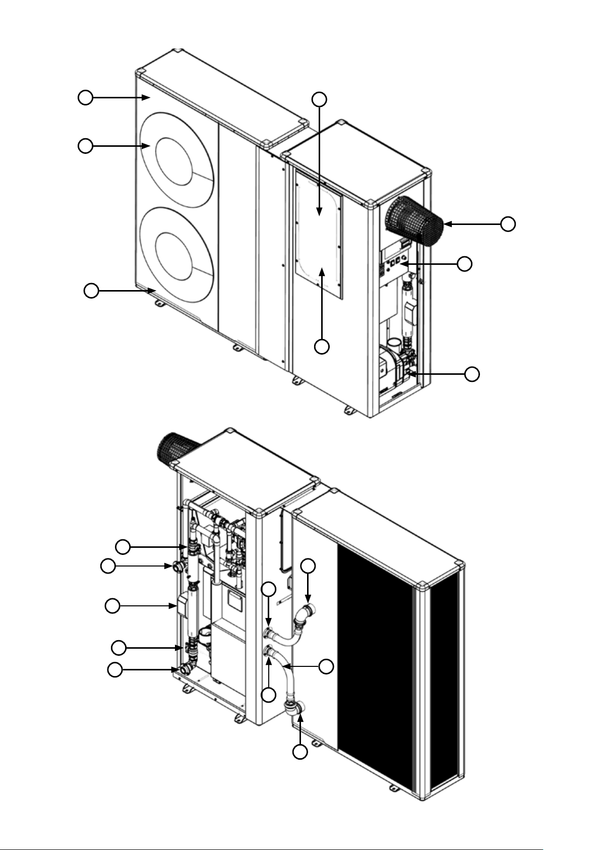
1.9 Hybrid Components
8
7
6
1
2
3
5
4
Figure 1-5: Main components - front
18
17
16
15
14
9
13
10
12
Figure 1-6: Main components - rear (oil boiler casing removed)
11
Section 1: IntroductionPage 6

13
12
21
22
19
20
Figure 1-7: Knockouts for oil lines and condensate disposal
Table 1-8: Key to main components - front
Key Item
1
2 Flue (external applications) Refer to Section 13
3 Control panel Refer to Section 10
4 Blue flame burner A Riello high-efficiency, low NOx blue flame burner with plug and socket connection
5 Pump High efficiency circulating pump
6 Anti-freezing heater Factory fitted electric heater prevents condensate in the base of the heat pump from freezing
7 Fa n
8 Air inlet Located in the left and back of the heat pump
9 Flow Refer to Section 5
10 Flexible hose
11 Return Refer to Section 5
12 Heat pump return Refer to Section 5
13 Heat pump flow Refer to Section 5
14 System return Refer to Section 5
15 Isolation valve Refer to Section 4 (if heat meter is fitted)
16 Heat meter Refer to Section 4 (if heat meter is fitted)
17 System flow Refer to Section 5
18 Isolation valve Refer to Section 4 (if heat meter is fitted)
19 Condensate trap
20 Condensate knockout
21
22 Oil line knockouts Refer to Section 3
Not shown
Front (removable) access
cover
Condensate knockout
(base - not shown)
Heat exchanger Award winning condensing heat exchanger
DC Inverter
Compressor A high-efficiency DC t win-rotary compressor to provide smooth performance and quiet operation.
Plate Heat Exchanger
(Condenser)
Circulating Pump High-efficiency DC pump speed controlled from the ASHP control PCB.
Pressure Relief Valve A 3 bar pressure relief valve is factory fitted.
Air Purge Valve (Automatic
Air Vent)
To access the heat pump wiring centre
A high-efficiency DC fan motor is used for smo oth and quiet operation. Two fans (3 blade) are fitted to the
16kW unit.
Refer to Section 9
This responds rapidly to changing conditions to provide the necessary output to meet heating demands by
varying the speed and output of the compressor, fan and circulating pump.
This reduces the on/off times of the compressor, ke eping the water temperature constant during operation
reducing the electricity consumption.
The high-efficiency plate heat exchanger is used to transfer heat to the heating system primar y circuit.
Factory fitted to assist in the removal of air from the heating primary circuit of the heat pump.
Section 1: Introduction Page 7

2 Technical Data
2.1 Boiler Technical Data
Table 2-1: Boiler technical data
Unit HPIDAIR - 15/21kW HPIDAIR2 - 21/26kW
Water content - oil boiler / heat pump (total)
Weight - oil boiler and heat pump (empty)*
Weight - oil boiler and heat pump (full)*
Maximum heat output (Kerosene)**
Heating system flow connection 1" BSP female
Heating system return connection 1" BSP female
Minimum flow rate (∆T=8°C) litres/min. 15
Condensate connection 22 mm (only connect plastic pipe)
Waterside resistance (∆T=10°C) mbar 26
Waterside resistance (∆T=20°C) mbar 9.5
Maximum static head metre 28
Minimum circulating head metre 1
Boiler thermostat range °C 65 to 78
Limit (safety) shut of f temperature °C 111 ± 3
Maximum hearth temperature °C Less than 50
Electricity supply 230/240V 1ph 50Hz fused at 5A
Burner motor power Watts 90
Absorbed motor power Watts 0.15
Starting current Amps 2.0
Running current Amps 0.85
Oil connection ¼" BSP male (on end of flexible tube)
Maximum operating pressure - sealed system bar 2.5
Maximum operating pressure - pressure relief valve bar 2.0
* Weight includes burner but excludes flue.
** Factory setting (ma ximum output). Refer to Section 2.4 for other boiler outputs.
litre 16.5 / 2.0 (18.5) 10.5 / 2.0 (12.5)
gallon 3.6 / 0.44 (4.04) 2.3 / 0.44 (2.74)
kg 270 272
lb 595 600
kg 290.2 286.5
lb 639.8 631.6
kW 21 26
Btu/h 71 694 88 764
2.2 Heat Pump Technical Data
For technical data relating to the heat pump, please refer to the Aerona³ installation and servicing instructions supplied with the heat pump.
Section 2: Technical DataPage 8
2.3 Sealed System Data
Table 2-2: Sealed system data
15/21 and 21/26kW
Heating system pressure (cold) Maximum 1.0 Minimum 0.5 bar
Operating pressure of pressure relief valve 2.5 bar
Expansion vessel size (pre-charged at 1 bar) To be selected based on the water content of the system
Cold water mains connection * 15 mm copper pipe
Pressure relief valve discharge connection * 15 mm copper pipe
* Provided that a Grant UK sealed system kit (listed in Table 1-4) has been used
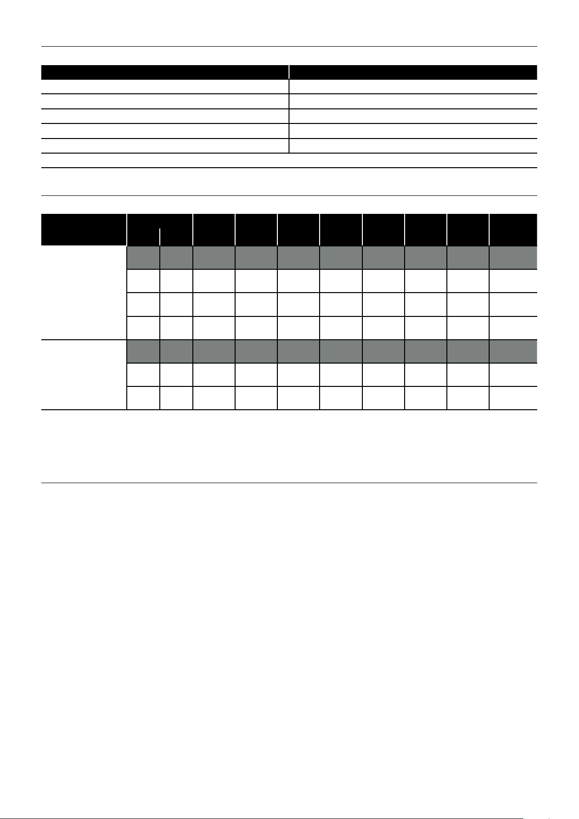
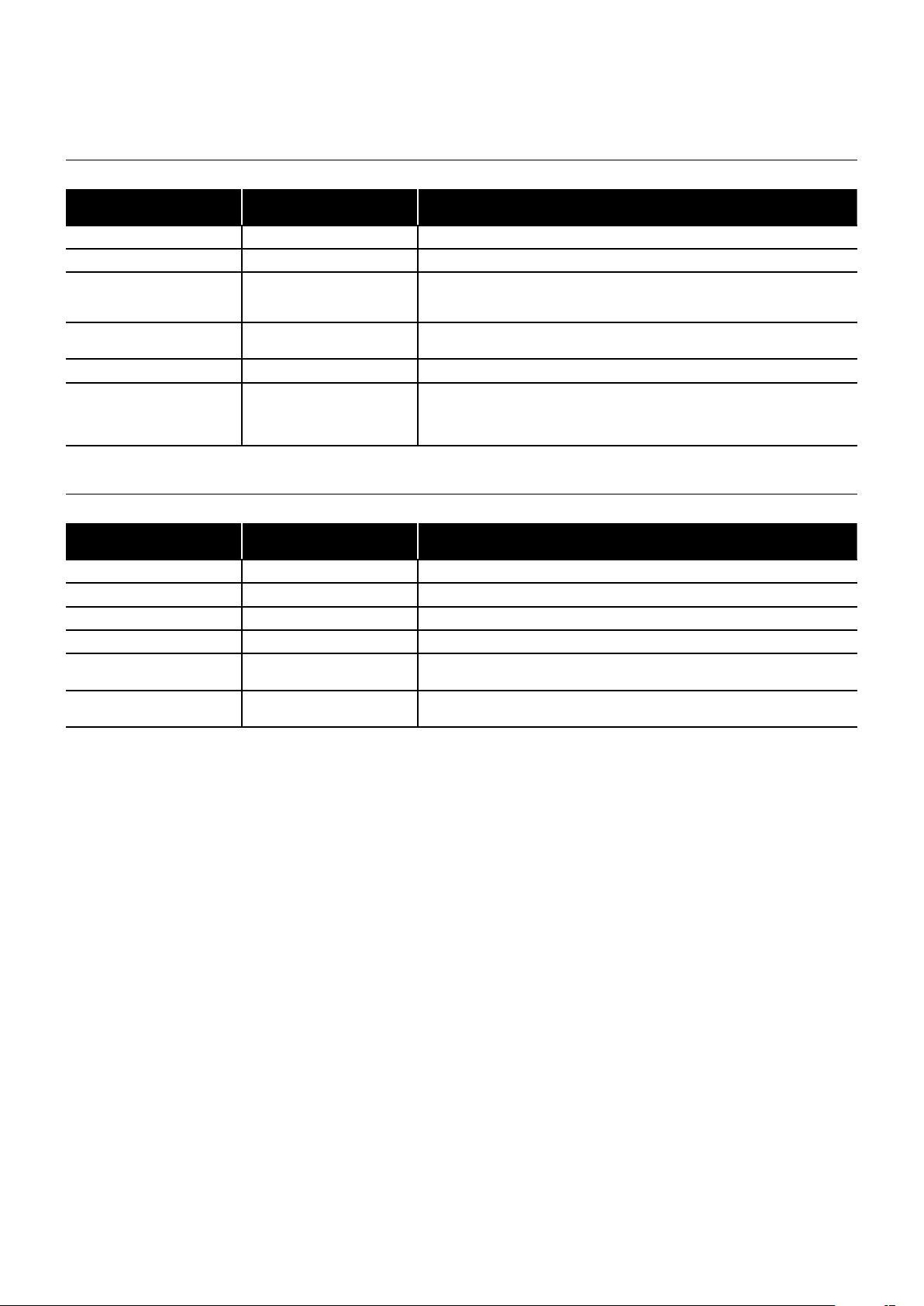
2.4 Burner Settings
Table 2-3: Burner settings
Hybrid model
(burner type)
HPIDAIR
15/21kW
(RDB2.2 BG1 BLU)
HPIDAIR2
21/26kW
(RDB2.2 BG3 BLU)
Notes:
1. The data given above is approximate only.
2. The above settings may have to be adjusted on site for the correct operation of the burner.
3. Gas Oil and Bio Kerosene are NOT suitable for use with the Grant HybridAir
4. The flue gas temperatures given above are ± 10%.
5. When commissioning, the air damper must be adjusted to obtain the correct CO
6. * Factory settings: 15/21 - 21kW, 21/26 - 26kW
7. The installer must amend the boiler data label if the output is changed.
Heat output
(kW) (Btu/h)
* 21 * 71 650 0.60/80°ES 8.5 0 - 1 BG1 N/A 1.78 55 - 85 12.0
15 51 200 0.40/80°ES 9.0 0 - 1 BG1
16 54 600 0.40/80°ES 10.5 0 - 1 BG1
18 61 400 0.55/80°ES 8 0 - 1 BG1 N/A 1.53 50 - 80 12.0
* 26 * 88 700 0.65/80°ES 10 0 - 1 BG2 N/A 2.19 55 - 75 12.0
21 71 650 0.60/80°ES 8.5 0 - 1 BG2 N/A 1.78 45 - 65 12.0
23 78 475 0.65/80°ES 8.5 0 - 1 BG2 N/A 1.94 50 - 70 12.0
Nozzle
Oil
pressure
(bar)
Smoke
No.
Burner
head type
level.
2
Burner
head/disc
setting
Disc
setting B
Disc
setting B
Fuel
flow rate
(kg/h)
1.28 45 - 75 12.0
1.36 45 - 75 12.0
Flue gas
temp.
(°C)
CO
(%)
2
2.5 Flue Gas Analysis
To allow the boiler to be commissioned and ser viced, the boiler is supplied with a combustion test point on the front cleaning door. When
this test point is used please note the following:
• The test point is for CO2 and smoke readings only.
• The boiler efficiency and temperature must be taken from the flue test point on high level, vertical and conventional flue adaptors.
• Concentric low level flues do not contain a test point. The temperature and efficiency readings must be taken from the flue terminal.
Section 2: Technical Data Page 9
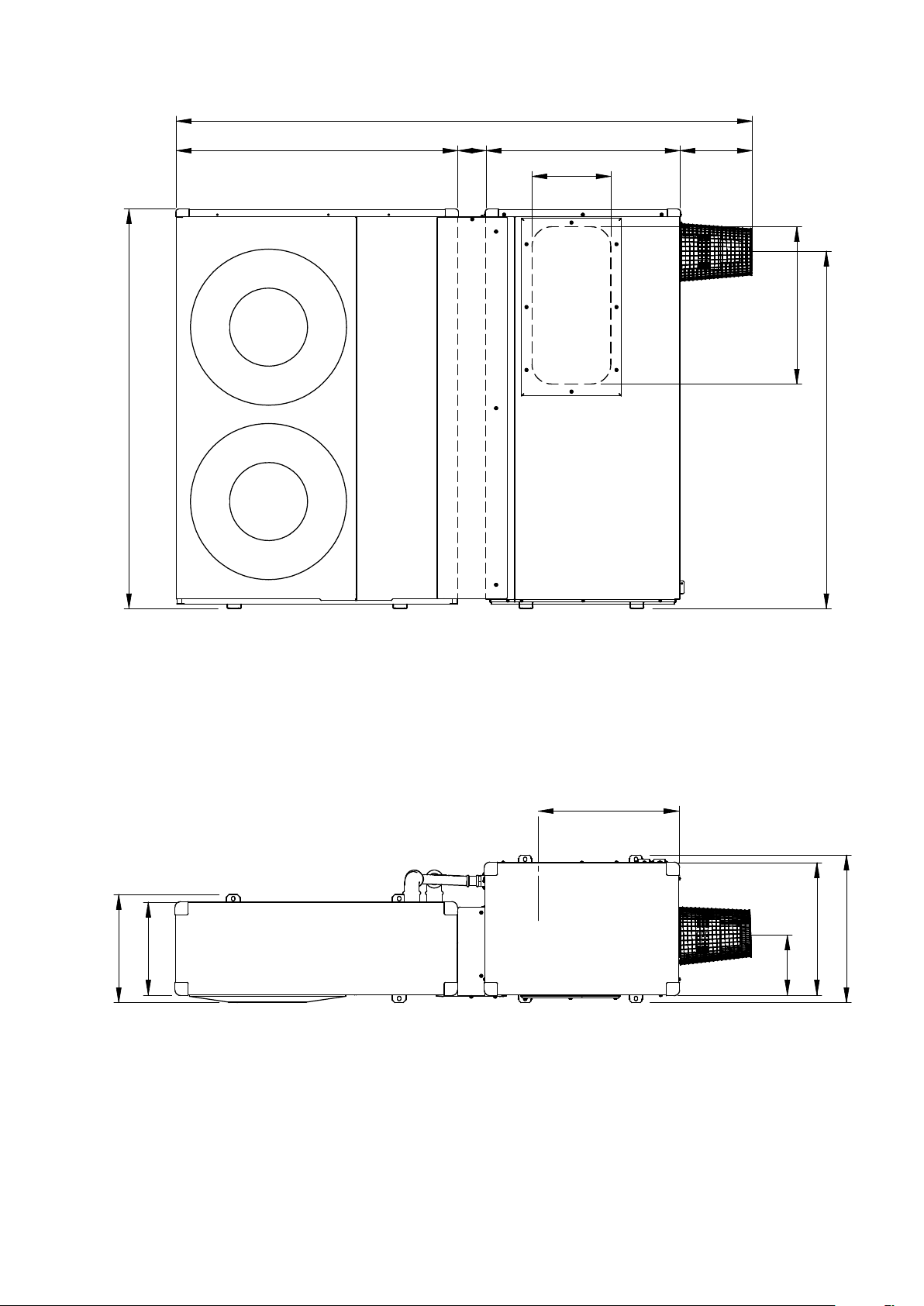
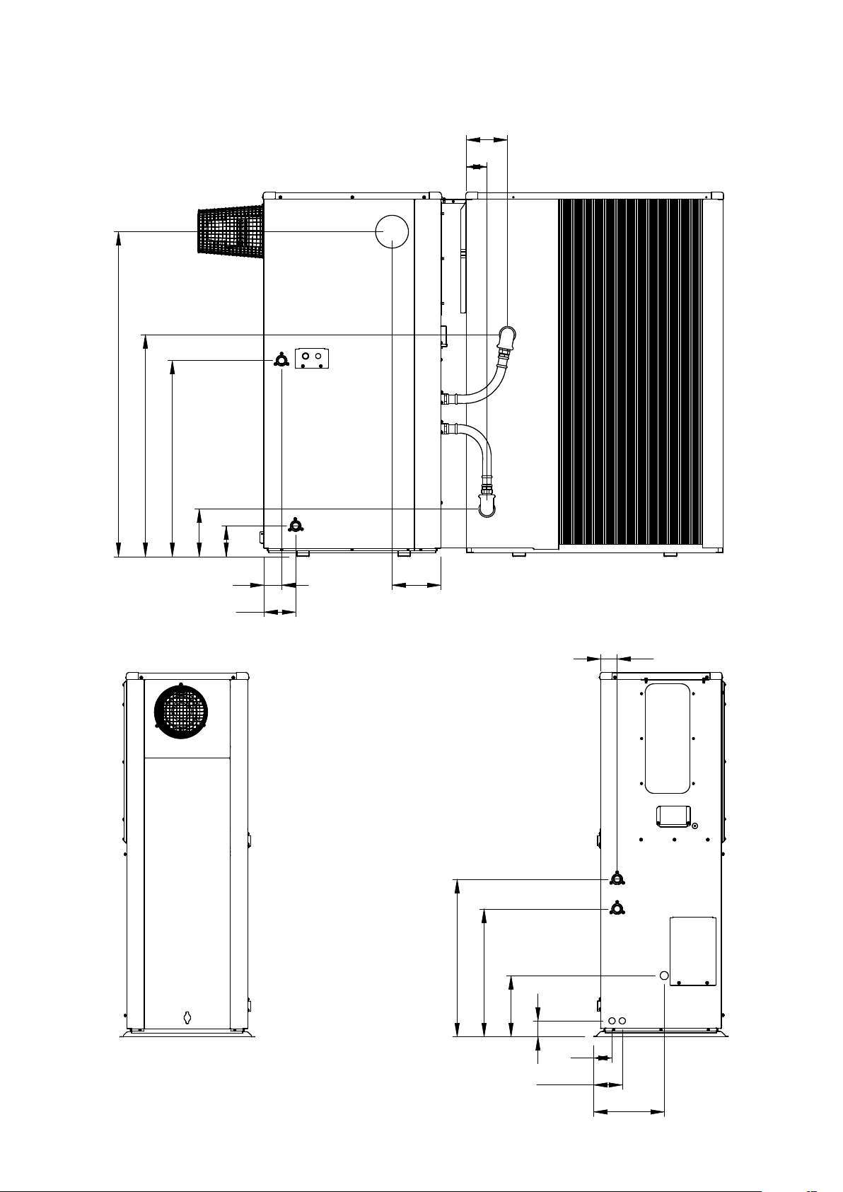
2.6 Hybrid Dimensions
2047
280
690100
257
560
1270
1000
1420
Figure 2-4: Hybrid front view
500
525
471
385
330
213
Figure 2-5: Hybrid top view
All dimensions in the diagrams are in millimetres.
Please note: all dimensions are excluding the feet (refer to Section 1.8).
For details of the heat pump only - refer to Aerona³ Installation Instructions supplied with the heat pump.
Section 2: Technical DataPage 10
1270
160
80
865
764
185
119
69
124
190
Figure 2-6: Hybrid rear view
65
613
498
Figure 2-7: Oil boiler right hand view
Section 2: Technical Data
238
62
72
112
275
Figure 2-8: Oil boiler left hand view
Page 11
2.7 Clearances
The following minimum clearances must be used to enable the unit to be easily commissioned, serviced and maintained.
In the case of the heat pump, these will allow for adequate air flow in and out of the unit.
2.7.1 Oil Boiler and Heat Pump Installed Externally
Table 2-9: Minimum clearances required for oil boiler and heat pump installed externally
Aspect
Top (above) 300
Bottom (below)
In front of unit
Rear of unit
Left-hand side
Right-hand side (burner end) 600
Minimum clearance required
(mm)
100 This is the height of
600
300 (from rear of heat pump)
150 (from rear of oil boiler)
100
Notes
Ensure that there is adequate clearance to remove the front access panel and that the
air discharged from the heat pump will not cause a nuisance.
Ensure that there is adequate clearance to remove the access panel, the burner and
to work upon the control panel.
IMPORTANT: This distance may have to be increased in order to comply with the flue
terminal clearances. Refer to Section 13.3.
2.7.2 Oil Boiler Installed Internally
Table 2-10: Minimum clearances required for oil boiler installed internally
Aspect
Top (above) 300
Bottom (below)
In front of unit
Rear of unit
Left-hand side
Right-hand side (burner end) 600
Minimum clearance required
(mm)
N/A
600 Ensure that there is adequate clearance to remove the front access panel.
150
600
Notes
Ensure that there is adequate clearance to remove the condensate trap access panel
and condensate trap.
Ensure that there is adequate clearance to remove the access panel, the burner and
to work upon the control panel.
anti-vibration mounts. Refer to Table 1-4.
2.7.3 Heat Pump Installed Externally
For clearances for the heat pump (only) installed externally, refer to Section 3.5.2 and Figure 3-2 of the Installation and Ser vicing Instructions
supplied with the Aerona³ unit.
Section 2: Technical DataPage 12
3 Oil Storage and Supply System
FROM PUMP
3.1 Fuel Supply
Fuel Storage
The tank should be positioned in accordance with the
recommendations given in BS 5410-1:2014, which gives details of
filling, maintenance and protection from fire.
A steel tank may be used and must be constructed to BS 7995:2010 and OFS T200.
!
A galvanised tank must NOT be used.
A plastic tank may be used and must comply with OFS T100.
!
Plastic tanks should be adequately and uniformly supported
on a smooth level sur face, across their entire base area, that
is, the area in contact with the ground.
Fuel Pipes
Fuel supply pipes should be of copper tubing with an external
diameter of at least 10 mm.
Galvanised pipe must not be used.
All pipe connections should preferably use flared fittings. Soldered
connections must not be used on oil pipes.
!
Flexible hoses must NOT be used outside the boiler casing.
A remote sensing fire valve must be installed in the fuel supply line,
with the sensing head located above the burner.
Recommendations are given in BS 5410-1:2014.
A suitable oil filter with a minimum 15µ filtration must be installed in
the oil supply line. A shut-off valve should be fitted before the filter,
to allow the filter to be serviced.
A flexible fuel line, adaptor and ¼" BSP isolation valve are supplied
loose with the boiler for the final connection to the burner. If a two
pipe system or 'Tiger Loop' type de-aerator is used, an additional
flexible fuel hose (900 mm) and 3/8" to 1/4" BSP male adaptor are
available to purchase from Grant UK (product codes: RBS35 and
RBS36).
Metal braided flexible hoses should be replaced annually when
the boiler is serviced. Long life flexible hoses should be inspected
annually and replaced at least every 60 months.
CAUTION
NOTE
CAUTION
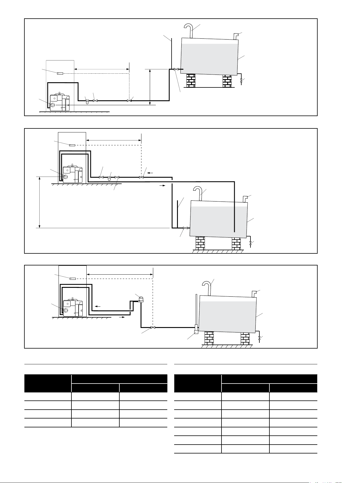
Single pipe system - (refer to Figure 3-2 and Table 3-5)
With the storage tank outlet above the burner a single pipe system
should be used. The height of the tank above the burner limits the
length of pipe run from the tank to the burner.
As supplied the burner is suitable for a single pipe system.
Two pipe system - (refer to Figure 3-3 and Table 3-6)
With the storage tank outlet below the burner, a two pipe system
should be used. The pipe runs should be as shown in Figure 3-2.
The return pipe should be the same level in the tank as the supply
pipe, both being 75 to 100 mm above the base of the tank. The pipe
ends should be a sufficient distance apart so as to prevent any
sediment disturbed by the return entering the supply pipe.
Avoid the bottom of the tank being more than 3.5 m below the
burner.
A non-return valve should be fitted in the supply pipe together with
the filter and fire valve. A non-return valve should be fitted in the
return pipe if the top of the tank is above the burner.
To be used with a t wo-pipe system, the burner must be fitted with an
additional flexible fuel hose - a flexible fuel hose (900 mm) and 3/8"
to 1/4" BSP male adaptor are available to purchase from Grant UK
(product codes: RBS35 and RBS36).
The pump vacuum should not exceed 0.4 bar. Beyond this limit gas
is released from the oil.
For guidance on installation of top outlet fuel tanks and suction oil
supply sizing, see OFTEC Technical Book 3. Available from OFTEC.
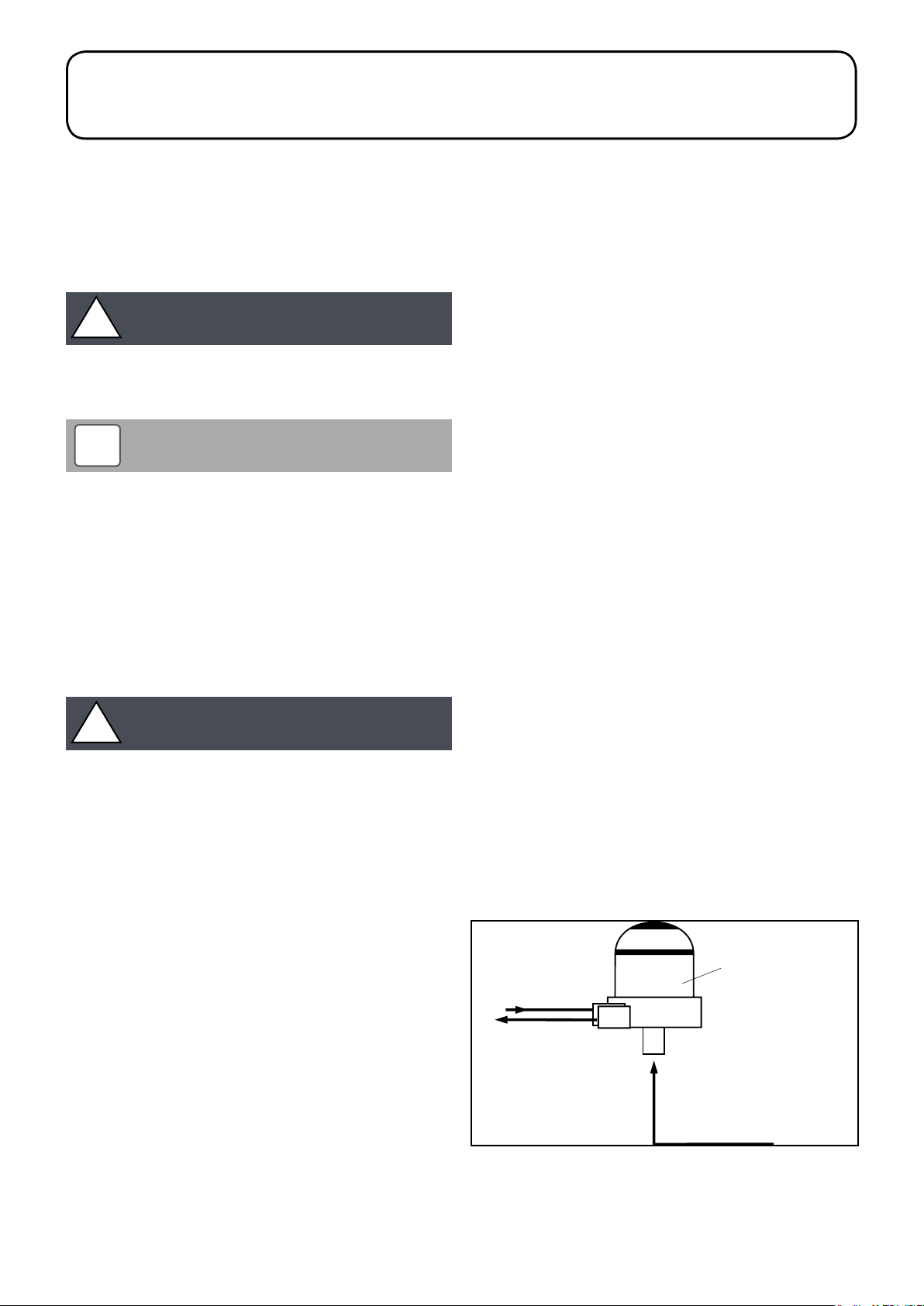
Tiger Loop system - (refer to Figure 3-1 and 3-4)
When The storage tank outlet is below the burner, an alternative to
a two pipe system can be achieved using a 'Tiger Loop' t ype oil
de-aerator. This ef fectively removes the air from the oil supply on a
single pipe lift.
The de-aerator is connected close to the boiler as a two pipe
system (omitting the non-return valve) as shown in Figure 3-3.
Refer to the manufacturers instructions supplied with the de-aerator.
The de-aerator must be mounted vertically. See Figure 3-3 and 3-4.
To be used with a de-aerator, the burner must be fitted with an
additional flexible fuel hose - a flexible fuel hose (900 mm) and 3/8"
to 1/4" BSP male adaptor are available to purchase from Grant UK
(product codes: RBS35 and RBS36).
RETURN
SUPPL Y
TO PUMP
Tiger Loop
1/4" BSP female
connections
Section 3: Oil Storage and Supply System Page 13
SUPPL Y
FROM TANK
Figure 3-1: Tiger loop de-aeration device
Vent
Fire
valve
sensor
Pump
Filter
Figure 3-2: Single pipe system
1 m
Shut-off
valve
Fire
valve
A
Level
gauge
pipe
Fill
pipe
Fuel
storage
tank
Sludge
valve
Shut-off
valve
Fire
valve
sensor
See
Section 3.2
A
Figure 3-3: Two pipe system
Fire
valve
sensor
See
Section 3.2
1 m
Non
return
valve
Filter
Shut-off
valve
1 m
De-aeration device
e.g. Tiger Loop
See Figure 3-1
Supply
Return
Fire
valve
Return
Supply
Shut-off
valve
Level
gauge
Vent
pipe
Fill
pipe
Fuel
storage
tank
Sludge
valve
Vent
pipe
Fill
pipe
Fuel
storage
tank
Fire valve
Figure 3-4: De-aeration device system
Table 3-5: Single pipe system maximum pipe runs
Head A
(m)
0.5 10 20
1.0 20 40
1.5 40 80
2.0 60 100
Maximum pipe run (metres)
10 mm OD pipe 12 mm OD pipe
Sludge
Tankmaster
valve
Table 3-6: Two pipe system maximum pipe runs
Maximum pipe run (metres)
10 mm OD pipe 12 mm OD pipe
Head A
(m)
0 35 100
0.5 30 100
1.0 25 100
1.5 20 90
2.0 15 70
3.0 8 30
3.5 6 20
Section 3: Oil Storage and Supply SystemPage 14
3.2 Burner Oil Connection
3
The burner fuel pump is supplied for use with a single pipe fuel
supply system. For use on a two pipe system, it is necessar y to fit
the by-pass screw, as shown in Figure 3-7, into the tapping in the
return port.
The by-pass screw is supplied in the boiler accessory pack.
1. Remove the plastic burner cover (secured by one screw).
For ease of access to the fuel pump, to fit the by-pass screw
and connect the oil lines, the burner can be removed from the
boiler. To do this, unscrew the single nut at the top of the burner
(using a 13 mm spanner) and withdraw the burner from the
boiler.
2. Remove and discard the blanking plug from the return
connection of the pump and fit the by-pass screw using an
hexagonal key.
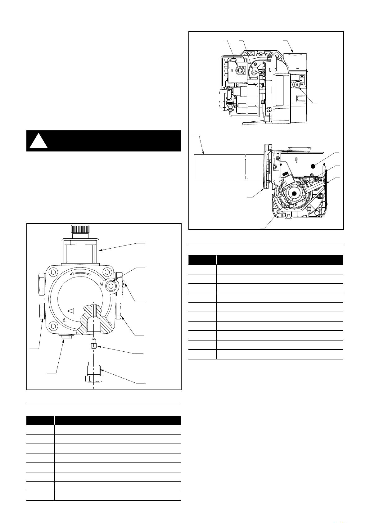
3.3 Burner Components
9
10
6
5
!
The blanking plug supplied in the inlet (suction) port may now
be plastic and will not provide an oil tight seal when the pump
is running. Ensure that the supply from the tank is connected
to this port and that the plastic plug is discarded.
3. Connect the return oil flexible fuel hose to the pump.
4. Connect the 3/8" to 1/4" BSP adaptor to the flexible fuel hose.
Flexible fuel hoses and adaptors are available to purchase from
Grant UK. Refer to Section 1.8.
WARNING
7
6
5
4
8
3
2
7
8
4
1
Figure 3-9: Riello RDB burner components
Table 3-10: Riello RDB burner components key
Key Description
1 Oil pump
2 Digital control box
3 Reset push-button with lockout lamp
4 Flange with insulating gasket
5 Air damper adjustment screw
6 Snorkel (balanced flue) connection
7 Pump pressure adjustment screw
8 Pressure gauge port
9 UV sensor
10 Combustion head
1
2
Figure 3-7: Riello RDB pump
Table 3-8: Riello RDB pump key
Item Description
1 Inlet (suction) port
2 Return port
3 By-pass screw
4 Pressure gauge port
5 Pressure adjustment
6 Vacuum gauge port
7 Solenoid
8 Auxiliar y pressure test point
Section 3: Oil Storage and Supply System Page 15

4 Installation Information
4.1 Introduction
!
Before star ting any work on the boiler or fuel supply, please
read the Health and Safet y information given in Section 18 of
these instructions.
Before star ting any work on the heat pump, please read
the Health and Safety information given in Section 14 of the
Aerona³ installation instructions.
This section gives a general overview of the installation process with
detailed installation information given in the following sections:
• Section 5 - Installing the Oil Boiler - pages 18 to 19
• Section 6 - Installing the Heat Pump - pages 20 to 21
• Section 7 - Installing the Heat Meters (where required) - pages
22 to 29
!
It is recommended, where possible, to fit the heat meter
during the installation of the oil boiler to avoid the need to
drain the system at a later date.
WARNING
NOTE
4.2 VortexAir location
4.2.1 Selection of position
• Consider a place where the noise, air and flue discharge will
not affect neighbours.
• Consider a position protected from the wind.
• Consider an area that reflects the minimum spaces
recommended.
• Consider a place that does not obstruct the access to doors or
paths.
• The surfaces of the floor must be solid enough to suppor t the
weight of the VortexAir and minimise the transmission of noise
and vibration.
• Take preventive measures so that children cannot reach the
unit.
• Install the VortexAir in a place where it will not be inclined more
than 5°.
• When installing the VortexAir where it may exposed to strong
wind, brace it securely.
Decide the mounting position as follows:
• Install the VortexAir in a level location which can withstand the
weight of the heat pump and vibration.
• Provide the indicated space to ensure good airflow.
• Do not install the VortexAir near a source of heat, steam, or
flammable gas.
• During heating operation, condensate water flows from the heat
pump. Therefore, install the heat pump in a place where the
condensate water flow will not be obstructed.
• Do not install the heat pump where strong wind blows directly
onto the heat pump or where it is very dusty.
• Do not install the VortexAir where people pass frequently.
• Install the VortexAir in a place where it will be free from adverse
weather conditions as much as possible.
•
4.2.2 Noise Level (heat pump)
All heat pumps make a noise. Discuss the potential nuisance factor
with the end-user when considering the final position of the heat
pump. Take opening windows and doors into account. It is not
essential for the heat pump to be positioned next to a wall of the
house. Behind an out-building may be more suitable so discuss the
options with the end-user.
4.2.3 Orientation (heat pump)
The North face of the building will usually have colder ambient air
than any other side. To ensure ma ximum ef ficiency from the Grant
UK Aerona³ heat pump, position the heat pump on a warmer side. In
order of preference, site the heat pump on a South face followed by
either South East or South West, then by East or West. Only install
on a North face if there is no other alternative.
4.3 Preparation for Installation
4.3.1 Base (boiler and heat pump installed externally)
The heat pump and boiler should be installed on a flat trowelled
finished concrete base 150 mm thick. This base should extend at
least 150 mm beyond the heat pump and boiler on three sides.
To avoid bridging the DPC, leave a gap of at approximately 150 mm
between the concrete base and the wall of the house.
The VortexAir unit must be raised up from the base by approximately
100mm on suitable anti vibration mounts or blocks - two each for
the boiler and the heat pump (refer to Table 1-4).
The VortexAir can be installed either against the building or 'free
standing' some distance away from the building.
4.3.2 Base (boiler installed internally)
The boiler must stand on a firm and level surface. The boiler base
temperature is less than 50°C so no special hearth is required.
4.3.3 Clearances
The minimum clearances given in Section 2.7 must be used to
enable both the boiler and heat pump of the VortexAir to be easily
commissioned, serviced and maintained and allow adequate air
flow in and out of the heat pump.
4.4 Regulations and Standards
Installation of a Grant VortexAir must be in accordance with the
following recommendations:
• Building Regulations for England and Wales, and the Building
Standards for Scotland issued by the Department of the
Environment and any local Byelaws which you must check with
the local authority for the area.
• Model and local Water Undertaking Byelaws.
• Applicable Control of Pollution Regulations.
The following OFTEC requirements:
• OFS T100 Polythene oil storage tanks for distillate fuels.
• OFS T200 Fuel oil storage tanks and tank bunds for use with
distillate fuels, lubrication oils and waste oils.
Further information may be obtained from the OFTEC Technical
Book 3 (Installation requirements for oil storage tanks) and OFTEC
Technical Book 4 (Installation requirements for oil fired boilers).
The installation should also be in accordance with the latest edition
of the following British Standard Codes of Practice:
• BS 715 Metal flue pipes, fittings, terminals and accessories.
• BS 799:5 Oil storage tanks.
• BS 1181 Clay flue linings and flue terminals.
Section 4: Installation InformationPage 16

• BS 4543:3 Factory made insulated chimneys for oil fired
appliances.
• BS 4876 Performance requirements for oil burning appliances
• BS 5410:1 Code of Practice for oil firing appliances.
• BS 5449 Forced circulation hot water systems.
• BS 7593 Code of Practice for treatment of water in heating
systems.
• BS 7671 Requirements for electrical installations, IET Wiring
Regulations.
For a list of recommendations and regulations to the heat pump,
refer to the Installation and Servicing Instructions supplied with the
heat pump.
Grant Engineering (UK) Limited strongly recommends that
a Grant MagOne in-line magnetic filter/s (or equivalent*)
is fitted in the heating system pipework. This should be
installed and regularly serviced in accordance with the filter
manufacturer’s instructions.
* As measured by gauss. The MagOne magnetic filter has a gauss
measurement of 12000.
!
We recommend that both antifreeze and corrosion inhibitor
be used in the primary water system.
NOTE
4.5 Completion
Please ensure that the OFTEC CD/10 installation completion report
(provided with the boiler) is completed in full.
Leave the top copy with the User.
Retain the carbon copy.
Ensure that:
a. The User Information pack (supplied with the boiler) is handed
over to the Householder.
b. The householder is aware of how to use the product.
c. The householder is aware of the need to refer to the online
calculator and change the stat.
d. The product is registered for the Grant product guarantee.
4.6 Before you Commission
4.6.1 Flushing and Corrosion Protection
To avoid the danger of dir t and foreign matter entering the VortexAir
the complete heating system should be thoroughly flushed out
– both before the VortexAir is operated and then again af ter the
system has been heated and is still hot.
This is especially important where the VortexAir is installed as a
replacement for a boiler on an existing system.
In this case the system should be first flushed hot, before the old
boiler is removed and replaced by the VortexAir.
For optimum performance after installation, this VortexAir and the
central heating system must be flushed in accordance with the
guidelines given in BS 7593:2006 ‘Treatment of water in domestic
hot water central heating systems’.
This must involve the use of a proprietary cleaner, such as Sentinel
X300 or X400, or Fernox Restorer.
After flushing, a suitable thermal fluid should be used (such as
Sentinel R600) specifically designed for use in air source heat pump
installations. This provides long term protection against corrosion
and scale as well as the risk of the freezing in the ex ternal section of
the heating system (i.e. the flexible hoses, condenser and circulating
pump within the heat pump casing) in the event of power failure
during winter months.
In order to avoid bacterial growth, due to the lower system operating
temperatures, a suitable Biocide (such as Sentinel R700) should
also be used in conjunction with the thermal fluid.
Both the thermal fluid and biocide should be added to the system
water when finally filling the heating system.
Alternatively, Fernox HP5C can be used (or HP15C for greater frost
protection).
This is a suitable thermal fluid that already contains a suitable
biocide.
Full instructions on the correct use of thermal fluids and biocides are
supplied with the products, but further information can be obtained
from either ww w.sentinel-solutions.net or ww w.fernox.com.
Failure to implement the above guidelines by fully flushing the
system and using a suitable thermal fluid and biocide corrosion
inhibitor will invalidate the heat pump product guarantee.
4.7 Heating System Design Considerations
To achieve the ma ximum ef ficiency possible from the Grant
VortexAir, the heating system should be designed to the following
parameters:
Radiators:
• Flow temperature 70°C, return temperature 50°C, differential
20°C
Underfloor:
• Flow temperature 50°C, return temperature 40°C, differential
10°C
Size radiators with a mean water temperature of 60°C.
Design system controls with programmable room thermostats or
use weather compensating controls to maintain return temperatures
below 55°C.
!
The boiler should not be allowed to operate with return
temperatures of less than 40°C when the system is up to
operating temperature.
The use of a pipe thermostat is recommended to control the return
temperature when using weather compensating controls.
NOTE
4.8 Underfloor Heating Systems
In underfloor systems it is essential that the return temperature must
be maintained above 40°C to prevent internal corrosion of the boiler
water jacket.
4.9 Pipework Materials
Grant VortexAir units are compatible with both copper and plastic
pipe. Where plastic pipe is used it must be of the oxygen barrier
type and be of the correct class (to BS 7291-1:2010) for the
application concerned.
!
The first metre of pipework connected to both the heating
flow and return connections of the boiler must be made in
copper.
WARNING
4.10 Underfloor Pipework
Plastic pipe may be used on underfloor systems where the plastic
pipe is fitted after the thermostatic mixing valve.
Copper tube must be used for at least the first metre of flow and
return primary pipework between the boiler and the underfloor
mixing/blending valves.
Section 4: Installation Information Page 17

5 Installation of the Oil Boiler
5.1 Preparation for Installation
1. Carefully remove the packaging from the boiler and remove it
from the transit pallet.
2. The oil supply line should be installed up to the position of the
boiler. Refer to Section 3 for details.
3. The final connection into the boiler enclosure can be made
when the boiler is in position. Using 10 mm soft copper, route
the oil line(s) into the boiler casing through the hole(s) provided
in the lower left corner of the left-hand casing panel. Refer to
Figure 1-7. Run it along the base of the enclosure (between
rear casing panel and the boiler) up to the burner located at the
right hand end of the enclosure. Refer to Section 3.2 for details
of the connection to the burner.
4. Position the boiler in the final location required, raised up from
the base by approximately 100 mm on suitable anti-vibration
mounts. This location may be either inside or outside the
building, as required.
• If the boiler is to be installed externally (next to the heat pump),
refer to Section 5.2.
• If the boiler is to be installed internally (with the heat pump
outside), refer to Section 5.3.
5.2 Installing the Oil Boiler – External location (nex t
to the heat pump)
1. With the boiler in the required position, ensure that the flue
terminal position complies with the necessary clearances.
Refer to Section 2.8.
2. Mark the wall and drill holes for the system flow and return
pipes. Refer to Figures 2-6 and 5-2 for the positions of the
pipework connections in the boiler rear panel.
3. Make the water connections as described in Section 8.4. If
access will be restricted, make any connections to the boiler
(and heat pump) before placing it in its final position.
4. Pipework should be insulated where it passes through the wall.
5. The boiler must be fitted to a sealed heating system. Refer to
Section 10 for details.
6. Ensure the requirements for the disposal of condensate as
described in Section 9 are met.
7. Connect the power supply to the hybrid control panel (in the
boiler) as described in Section 12.
8. Connect the flue system as described in Section 13.
5.3 Installing the Oil Boiler – Internal Location (with
heat pump outside)
1. With the boiler in required position, ensure that the flue terminal
position will comply with the necessary clearances. Refer to
Section 2.7.
2. Prepare the wall for the pipework and flue system. Mark the wall
and drill holes for the system flow and return pipes between the
boiler and the heat pump. Refer to Figures 2-6 and 5-2 for the
positions of the pipework connections in the boiler rear panel.
3. Mark the wall and make a hole for the flue system to pass
through. Refer to Section 13-.4 for the correct hole position.
4. Fit the flue system to the boiler as detailed in Section 12.5.
Ensure that there is an adequate air supply to the boiler if
required. Refer to Section 12.2.
5. Make the water connections as described in Section 8.4. If
access will be restricted, make any connections to the boiler
(and heat pump) before placing it in its final position.
6. The boiler must be fitted to a sealed heating system. Refer to
Section10 for details.
7. Ensure the requirements for the disposal of condensate as
described in Section 9 are met.
8. Connect the power supply to the hybrid control panel (in the
boiler) as described in Section 12
5.4 Boiler Only Operation (inside or outside
location)
5.4.1 Heat pump flow and return connections
If the boiler and heat pump are not to be installed at the same time,
but the boiler is required to operate immediately, e.g. following an
emergency boiler replacement, the boiler can be operated as a
‘stand-alone’ unit.
To do this the heat pump flow and return connections on the boiler,
located at the rear of the left side casing panel, must be connected
together.
This can be done by using 1" BSP x 28mm compression connectors,
as follows:
1. Using a suitable thread sealant or PTFE tape, screw one of the
connectors into the 1”BSPF ‘Heat Pump Flow’ connection on
the boiler.
2. Repeat the above process to fit the second connector to the
1”BSPF ‘Heat Pump Return’ connection on the boiler.
3. Make a 'U' section of 28mm Copper pipe (using either
two compression or capillary elbows). Fit this into the two
compression connections on the boiler to complete the loop
and tighten both compression fittings.
4. Insulate the connection bet ween the heat pump flow and return
connections. Even though this loop may only be a temporar y
measure, until the heat pump is installed, it MUST be insulated
using a suitable external insulation material.
5. Fill the sealed heating system as described in Section 10 of
these instructions.
6. Vent the system to remove trapped air using the manual air
vents located inside the boiler enclosure (refer to Figures 8-2
and 8-3).
Section 5: Installation of the Oil BoilerPage 18

!
WARNING
!
WARNING
If the boiler is to be used without the heat pump fitted, the
heat pump flow and return connections on the boiler MUST be
connected together, as described above, BEFORE the system
and boiler are filled with water.
5.4.2 ‘Boiler only’ controls
If the boiler is to be used as a ‘stand-alone’ unit, without the heat
pump connected, the ‘Oil/Hybrid’ switch on the Hybrid control panel
(in the boiler) MUST be set to ‘Oil’ for the boiler to operate.
Depending on the hot water controls option fitted, it may be
necessary to alter either the connections to the heating system
controls terminal block (in the hybrid control panel) in the boiler or
change the control settings for the boiler to operate to heat a hot
water cylinder. Refer to Section 11 for details of the hot water control
options and Section 12 for details of the electrical connections.
Table 5-1: Flow and return key
Item Description Item Description
1 System return (1" BSP female) 4 Return (1¼" BSP male)
2 System flow (1" BSP female) 5 Heat pump return (1" BSP female)
3 Flow (1¼" BSP male) 6 Heat pump flow (1" BSP female)
Any such changes to connections or settings MUST be
reversed when the heat pump is connected to the boiler and
operation of both together as a hybrid unit is required.
2
3
6
5
1
4
Figure 5-2: Flow and return connections
Section 5: Installation of the Oil Boiler Page 19

6 Installation of the Heat Pump
6.2 Installing the Heat Pump – Next to Oil Boiler
!
Ensure that the electrical supply to the boiler has been
isolated at the lockable isolator BEFORE commencing the
installation and connection of the heat pump.
WARNING
6.1 Preparation for Installation
• Carefully remove the packaging from the heat pump and
remove it from the transit pallet.
• Position the heat pump in the final location required, raised
up from the base by approximately 100 mm on suitable antivibration mounts.
This location may be either:
• Next to the boiler, if the boiler is installed externally. Refer
to Section 6.2
OR
• Freestanding outside, if the boiler is installed internally.
Refer to Section 6.3
!
If the boiler has been operated as a ‘stand-alone’ unit prior to
the installation of the heat pump, the loop bet ween the heat
pump flow and return connections on the boiler (as described
in Section 5.4.1) will now have to be removed to connect the
heat pump.
To avoid draining the heating system it is possible to close valves
in both the flow and return pipework within the boiler enclosure.
Referring to Figures 8-2 and 8-3, the isolation valves for the heat
meter flow sensor (13) and heat meter in the return (3) should be
closed before removing the loop bet ween the heat pump flow and
return connections on the boiler.
NOTE
(External oil boiler)
6.2.1 Electrical connections
1. Before moving heat pump into final position, remove the
wiring cover from the right hand end of the heat pump. Refer
to Section 6 of the Installation Instructions supplied with the
Aerona³ heat pump for details.
2. Remove the access panel from the front of the boiler casing.
Unscrew and remove the eight screws that secure the access
panel to the casing. Refer to Figure 12-1.
3. Working from inside the boiler enclosure, remove the internal
access cover in the left casing panel of the boiler. Slacken
off all six retaining screws. Lift the panel upwards and of f the
retaining screws using the keyhole slots.
4. Remove the t wo screws from the top lef t edge of the boiler
enclosure and fit the top spacer plate provided with the boiler.
Re-fit and tighten the screws to secure it in position on the
boiler enclosure.
5. Manoeuvre the heat pump into position such that the top
spacer plate butts against the heat pump enclosure across the
full depth of the heat pump, giving a gap between the boiler
and heat pump of 100mm.
6. Make the heat pump electrical supply connection bet ween the
heat pump electrical supply terminal block in the hybrid control
panel (in the boiler) and the electrical supply terminal block in
the Aerona³ heat pump.
Refer to Section 12 for electrical connection details. Figure 1210 shows the location of this terminal block and Figure 12-11 is
the connection diagram.
7. Make the heat pump controls connection bet ween the heat
pump controls terminal block in the hybrid control panel (in the
boiler) and the Terminal PCB in the Aerona³ heat pump.
Refer to Section 12 for electrical connection details. Figure 1212 shows the location of this terminal block and Figure 12-13 is
the connection diagram.
8. Working from both outside and through the access opening
in the left casing panel of the boiler, as required, replace
the wiring cover on the right hand end of the heat pump and
secure in place with the three fixing screws.
9. Replace the internal access cover in the lef t casing panel of the
boiler. Fit the keyhole slots onto the six retaining screws. Pull it
down and tighten the screws to secure it in position.
10. When all wiring connections have been made, re-fit the upper
cover panel at the rear of the control panel and secure it using
the two screws at the top of the cover. Refer to Figure 12-3.
11. Then replace the lower cover panel at the rear of the control
panel and secure it using the two screws. Refer to Figure 12-3.
12. Replace the access panel on the front of the boiler casing. Refit and tighten the eight screws to secure the access panel to
the casing. Refer to Figure 12-1.
Section 6: Installation of the Heat PumpPage 20

6.2.2 Pipework connections
Make the flow and return connections between the boiler and heat
pump, using the fittings provided with the boiler, as follows:
1. Using a suitable thread sealant or PTFE tape, screw one of
the two flexible hoses into the 1”BSPF ‘Heat Pump Flow’
connection on the boiler.
2. Repeat the above process to fit the second flexible hose to
the1”BSPF ‘Heat Pump Return’ connection on the boiler.
3. Using a suitable thread sealant or PTFE tape screw the
1”BSPM x 28mm tail into the 1” x 1¼” elbow. Then fit the elbow
to the flow connection (the higher of the two connections) on
the rear of the heat pump.
4. Fit the 28mm compression connection on the end of the flexible
hose from the heat pump flow connection (on to the boiler) on
to the tail fitted to the heat pump flow connection. Tighten the
compression connection.
5. It may be necessar y to adjust the angle of the elbow/tail on the
flow connection to align it with the compression connection on
the end of the flexible hose.
6. Repeat steps 4 and 5 above to connect the heat pump return
on the boiler with the flow connection on the heat pump.
7. Fill the sealed heating system as described in Section 10 of
these instructions.
8. Vent the system to remove trapped air using the manual air
vents located inside the boiler enclosure (refer to Figures 8-2
and 8-3) and also the automatic air vent in the heat pump (refer
to Section 1 of the Installation Instructions supplied with the
Aerona³ heat pump.
6.3 Installing the Heat Pump – Separate from Oil
Boiler (Internal oil boiler)
6.3.1 Electrical connections
1. Move the heat pump into the required final position. Ensure that
it does not obstruct the flue terminal and that the flue terminal
position complies with the necessary clearances. Refer to
Section 2.8.
2. Remove the wiring cover from the right hand end of the
heat pump. Refer to Section 6 of the Installation Instructions
supplied with the Aerona³ heat pump for details.
3. Remove the access panel from the front of the boiler casing.
Unscrew and remove the eight screws that secure the access
panel to the casing. Refer to Figure 12-1.
4. Make the heat pump electrical supply connection bet ween the
heat pump electrical supply terminal block in the hybrid control
panel (in the boiler) and the electrical supply terminal block in
the Aerona³ heat pump.
Refer to Section 12 for electrical connection details. Figure 1210 shows the location of this terminal block and Figure 12-11 is
the connection diagram.
5. Make the heat pump controls connection bet ween the heat
pump controls terminal block in the hybrid control panel (in the
boiler) and the Terminal PCB in the Aerona³ heat pump.
Refer to Section 12 for electrical connection details. Figure 1212 shows the location of this terminal block and Figure 12-13 is
the connection diagram.
6. Replace the wiring cover on the right hand end of the heat
pump and secure in place with the three fixing screws.
7. When all wiring connections have been made, re-fit the upper
cover panel at the rear of the control panel and secure it using
the two screws at the top of the cover. Refer to Figure 12-3.
8. Then replace the lower cover panel at the rear of the control
panel and secure it using the two screws. Refer to Figure 12-3.
9. Replace the access panel on the front of the boiler casing. Refit and tighten the eight screws to secure the access panel to
the casing. Refer to Figure 12-1.
6.3.2 Pipework connections
Make the flow and return connections between the boiler and heat
pump, using the fittings provided with the boiler, as follows:
1. Using a suitable thread sealant or PTFE tape screw one of
the 1” x 1¼” elbows (supplied with the boiler) on to the flow
connection (the higher of the two connections) on the rear of
the heat pump.
2. Repeat the same process for the return connection (the lower
of the two connections) on the rear of the heat pump.
3. Using a suitable thread sealant or PTFE tape, screw the
1”BSPM thread on one of the two flexible hoses (supplied with
the boiler) into the elbow on the heat pump flow connection.
4. Connect the other end of this flexible hose to the flow pipe from
the boiler using the 28mm compression connection.
5. Repeat the above process to fit the second flexible hose
between the elbow on the heat pump return connection and
the return pipe to the boiler.
6. It may be necessar y to adjust the angle of the elbows on the
heat pump flow and return connections to align it with the end
of the flexible hoses.
7. Fill the sealed heating system as described in Section 10 of
these instructions.
8. Vent the system to remove trapped air using the manual air
vents located inside the boiler enclosure (refer to Figures 8-2
and 8-3) and also the automatic air vent in the heat pump (refer
to Section 1 of the Installation Instructions supplied with the
Aerona³ heat pump.
6.4 Heat Pump Parameter Settings
When connected to the boiler as part of the VortexAir Hybrid unit,
some of the Control Parameter factory default settings must be
changed. Refer to Section 15.11 of these Installation Instructions for
details of the Control Parameters to be re-set.
Also, refer to Section 9 of the Installation Instructions supplied with
the Aerona³ heat pump for guidance on how to access and change
the Control Parameters.
Section 6: Installation of the Heat Pump Page 21

7 Installation of Heat and Electricity
Meters
7.1 General
As not all installations will require a heat meter and electricity
meter, the Grant VortexAir Hybrid is supplied without any meters
fitted. Usually only installations receiving a Renewable Heat
Incentive (RHI) payment will require both these meters to be
fitted.
Both meters are available as accessories from Grant UK for onsite fitting by the installer:
• Heat meter (Grant product code: HPIDMETER)
• Electricit y meter (Grant product code: HPIDKW/HMETER)
!
When required, only the meters supplied by Grant UK (as
listed above) must be used with the Grant VortexAir hybrid.
In accordance with MCS metering requirements, the Grant
VortexAir Hybrid is supplied ‘meter ready’ to allow both the heat
meter and electricity meter to be easily fitted when required, as
follows:
• The necessary temperature sensor points and valved
sections are incorporated in the pipework (inside the boiler
casing) for installation of the flow meter and temperature
sensors of the heat meter.
• A purpose made (DIN rail) mounting and housing is
provided for both the heat meter integrator unit and the
electricity meter.
• A 1A fused power supply for the heat meter is provided
within the meter housing.
• The incoming power to the heat pump is located inside the
meter housing for connection to the electricity meter.
NOTE
Electricity
meter
Heat
meter
Figure 7-1: Location of integrator meter when fitted
b) Flow meter (fluid oscillator flow sensor)
This measures the flow of water in the primary circuit when
the heat pump is operating. This flow rate can be displayed,
if required, on the integrator screen.
The flow meter is installed in the heating return pipe to the
heat pump. Refer to Figure 7-2. For details of how to install
the flow meter refer to Section 7.2.1.
7.2 Heat Meter
When correctly installed, this heat meter will measure and record the
heat produced by the heat pump only.
7.2.1 Description
The Sontex Superstatic 440 heat meter, supplied by Grant for
use with the Grant VortexAir Hybrid, consists of the following
components:
a) Integrator unit (Supercal 531)
This calculates the heat produced by the heat pump from
the information provided by the flow meter and the two
temperature sensors (see below). The heat produced by the
heat pump, along with the flow and return water temperatures,
can be displayed on the integrator screen if required.
Refer to Section 7.4 (or the Instructions supplied with the
heat meter kit) for guidance on how to access the information
available on the integrator screen.
When fitted, the integrator unit is located in a purpose made
housing immediately above the control panel. Refer to Figure
7-1.
Figure 7-2: Heating return pipework
c) Return temperature sensor
This measures the return water temperature. This
temperature can be displayed, if required, on the integrator
screen.
The sensor is fitted in a ‘dry pocket’ (supplied with the heat
meter kit) that is installed in a tapping located in the return
pipe to the heat pump (just above the flow meter). Refer to
Figure 7-2.
For details of how to install the return temperature sensor
refer to Section 7.2.5.
d) Flow temperature sensor
This measures the flow water temperature. This temperature
can be displayed, if required, on the integrator screen.
The sensor is fitted in a ‘dry pocket’ (supplied with the heat
Section 7: Installation of Heat and Electricity MetersPage 22

meter kit) which is installed in a tapping located in the flow
pipe from the heat pump. Refer to Figure 7-3.
For details of how to install the flow temperature sensor
refer to Section 7.2.6.
!
The two temperature sensors supplied with the heat meter
are a matched pair. They must both be used together, and
not replaced by any other sensor(s), as the sensors supplied
have been calibrated with the heat meter. The sensor cables
MUST NOT be either shortened or extended as this will affect
the measuring accuracy of the heat meter. They should run
independently of power cables to limit interference.
Figure 7-3: Sensor and pocket
WARNING
Figure 7-5: Kit contents (flow and return sensor coiled together)
7.2.3 Fitting the Integrator unit
To fit the flow meter integrator unit, use the following procedure:
1. Remove the top panel of the VortexAir boiler. To do so,
unscrew and remove the 10 screws around the four sides of
the top casing panel. Lift the top panel up and off the boiler
casing.
2. To access the control panel remove the boiler/burner
access panel on the right hand side of the boiler casing.
Turn the handle at the bottom clockwise to release the
catch. Pull the panel forwards at the bottom and remove it
from the boiler. Refer to Figure 7-6.
7.2.2 Kit Contents
Before fitting the heat meter, check that you have all the necessary
components, as follows (refer to Figure 7-4):
Table 7-4: Kit contents
Quantity Item
1
1
2
2
2
2
(not shown)
1
1
3
(not shown)
1
(not shown)
1
(not shown)
Sontex Superstatic flow meter DN25 G1¼”
(qp 3.5m³/hr)
Sontex Supercal 531 integrator
1¼”Union nut
1”BSP Union tail
Fibre washers
1” BSPM x 28mm compression connector
Pt500 flow temperature sensor (red tag)
Pt500 return temperature sensor (blue tag)
Sticker seals
(refer to Section 7.2.8)
Calibration report
(to be left with the end user following installation)
Sontex installation instructions
(to be left with the end user following installation)
Figure 7-6: Removal of boiler access panel
3. Remove the upper panel on the right hand side of the
boiler casing. Unscrew and remove the two panel retaining
screws (accessed from inside casing), lift the panel straight
up to disengage the two tags from their slots and remove
the panel from the boiler casing. Refer to Figure 7-7.
Section 7: Installation of Heat and Electricity Meters Page 23

6. Take the integrator unit and press in the four clips (two on each
side of the integrator unit) to release the front and carefully pull
it forwards to remove it from the rear section of the unit.
7. Pull out the tab on the rear of the LCD display to star t the clock.
Refer to Figure 7-14.
8. Push back and pull up the white plastic tab visible above the
top edge of the integrator (rear section) to open the DIN rail
clip on the back . Locate the rear section of the integrator unit
onto the DIN rail (at the left hand end of the rail) with the row of
cable grommets at the bottom.
9. Fully push the tab back down and check that the rear section of
the integrator unit us securely attached to the DIN rail.
7.2.4 Fitting the flow meter
Figure 7-7: Removal of upper side casing panel
4. Remove both the meter housing and cover (located
immediately above the control panel) from the boiler.
Unscrew the four screws (two on either side of the cover).
The meter housing and cover will come away together from
the boiler. Refer to Figure 7-8. Keep the four screws as they
will be required to re-fit the retaining bracket.
!
Whilst the flow meter and temperature sensors are best fitted
before the heating system is filled with water, they can be
fitted after filling if necessary.
To fit the flow meter use the following procedure:
1. Locate the removable section of pipe in the return to the
heat pump. Refer to Figure 7-9.
!
If the heating system has already been filled with water
ensure that the valves located both above and below this
section of pipe are CLOSED before removing the pipe.
NOTE
CAUTION
Figure 7-8: Removal of meter retaining bracket and cover
5. Cut the retaining cable ties and move the heat meter and
heat pump power supply cables to one side to gain access
to the DIN rail located behind the meter housing. Refer to
Figure 7-9.
Figure 7-9: Meter housing and DIN rail (with cover removed)
Figure 7-10: Location of removable pipe section
2. Unscrew the compression nuts at both the upper and
lower ends of the removable pipe section. Refer to Figure
7-10. Carefully lift the upper section of pipe just enough to
remove the pipe with the fittings attached at each end.
3. Remove the compression nut and olive from the 28mm
compression x 1”BSPF fitting (supplied with the heat meter)
and connect the fitting to the compression nut (just above
the lower isolating valve). Refer to Figure 7-10.
4. Using a suitable sealant or PTFE tape, fit one of the 1”BSP
threaded tails (provided with the flow meter) into the 1”
BSP socket. Ensure that the union nut is fitted on the tail
BEFORE it is screwed into the socket.
5. Repeat steps 3 and 4 above to fit the other 1”BSP threaded
tail and union nut (provided with the flow meter) into the
vacant upper 1” BSP socket. Refer to Figure 7-10.
Section 7: Installation of Heat and Electricity MetersPage 24

7.
Cable colours: R = Red, W = White, G = Green, Br = Brown, Bk = Black, Bl = Blue, G/Y = Green/yellow
Carefully route the cable from the flow meter through one
of the grommets in the side of the lower part of the control
panel and up to the integrator unit, installed immediately
above the control panel fascia.
8. The connection terminals are located towards the bottom
of the rear section of the integrator unit. Pierce the cable
grommet located in the lower face of the integrator unit
(below terminals 9, 10 and 11) and pass the flow meter
cable through.
9. The flow meter must be connected to terminals 10, 11 and
9 on the terminal block inside the Integrator unit, as follows:
• White wire – terminal 10
• Green wire – terminal 11
• Brown wire – terminal 9
Figure 7-11: Fitting of flow meter connections
6. Using the two fibre washers (provided with the flow meter),
fit the flowmeter between the joint faces of the upper and
lower tails and tighten the union nuts. Refer to Figure 7-12.
!
Ensure that the flow meter is installed such that the arrows on
the body of the unit are pointing UPWARDS.
Return temperature
sensor
Lower isolating valve
NOTE
Upper isolating valve
Return temperature
sensor pocket
!
Ensure that the metal ferrule (at the end of the flow meter
cable) is securely trapped under the metal cable clamp to
ground the flow meter cable. Refer to Figure 7-13 (integrator
connection diagram).
!
In order to comply with the Measuring Instruments Directive
(MID) 2004/22/EU the flow meter cable MUST NOT be
shortened. Any excess cable should be gathered up (coiled
up) in a suitable location, i.e. where it will not restrict access
to any component (valve, pump, etc.) within the boiler casing.
They should run independently of power cables to limit
interference.
NOTE
NOTE
Figure 7-12: Flow meter fitted
1 2 3 4 10 11 50 51 52 53 16 17 18 24 259
R W R W WGBr
Flow
temp
sensor
(Red)
Cable must be grounded by trapping the metal ferrule under the cable clamp.
Figure 7-13: Integrator connection diagram
Return
temp
sensor
(Blue)
Flow
meter
L N
Bk Bl
230V 50Hz 1ph
1A fused supply
G/Y
Section 7: Installation of Heat and Electricity Meters Page 25

7.2.5 Fitting the return temperature sensor
7.2.6 Fitting the flow temperature sensor
!
The return temperature sensor MUST be fitted in return
sensor pocket, as described below, and not fitted to (or on)
the return pipe in any other way.
To fit the return temperature sensor, use the following procedure:
1. Locate the return temperature sensor point on the return pipe
above the flow meter. Refer to Figure 7-12.
!
If the heating system has already been filled with water
ensure that the valves located both above and below this
section of pipe are CLOSED before removing the plug from
the sensor point.
Unscrew the plug from the temperature sensor point.
2.
3. Using a suitable sealant or PTFE tape, fit one of the t wo
temperature sensor pockets provided into the sensor point and
tighten, but only enough to achieve a seal.
4. Slacken of f the small clamp screw on the sensor pocket and fit
the stainless steel sensor fully into the sensor pocket. To ensure
the best operation of the temperature sensor (and heat meter),
first inject some heat conducting grease (not provided) into the
sensor pocket before inserting the sensor.
The sensor MUST be fitted fully into the pocket as far as it will
go. Then tighten the small clamp screw to secure the sensor
into the pocket. DO NOT OVERTIGHTEN!
5. Carefully route the cable from the return temperature sensor
through the same grommet as the flow meter cable (in the side
of the lower part of the control panel) and up to the integrator
unit, installed immediately above the control panel fascia.
6. Pierce the cable grommet located in the lower face of the
integrator unit (below terminals 3 and 4) and pass the flow
meter cable through.
7. The return temperature sensor must be connected to terminals
3 and 4 on the terminal block inside the Integrator unit, as
follows:
CAUTION
NOTE
• Red wire – terminal 3
• White wire – terminal 4
Refer to Figure 7-13 Integrator connection diagram.
Ensure that the cable is securely held under the metal cable
clamp.
!
The flow temperature sensor MUST be fit ted in flow sensor
pocket, as described below, and not fitted to (or on) the
return pipe in any other way.
To fit the flow temperature sensor, use the following procedure:
1. Locate the flow temperature sensor point. This is in the flow
pipe just above the insulated boiler jacket return pipe above the
flow meter. Refer to Figure 7-3.
!
If the heating system has already been filled with water
ensure that the valves located both above and below the flow
temperature sensor point are CLOSED before removing the
plug.
Unscrew the plug from the temperature sensor point.
2.
3. Using a suitable sealant or PTFE tape, fit one of the t wo
temperature sensor pockets provided into the sensor point and
tighten, but only enough to achieve a seal.
4. Slacken of f the small clamp screw on the sensor pocket and fit
the stainless steel sensor fully into the sensor pocket. To ensure
the best operation of the temperature sensor (and heat meter),
first inject some heat conducting grease into the sensor pocket
before inserting the sensor.
The sensor MUST be fitted fully into the pocket as far as it will
go. Then tighten the small clamp screw to secure the sensor
into the pocket. DO NOT OVERTIGHTEN!
5. Carefully route the cable from the flow temperature sensor
through the same grommet as the flow meter cable (in the side
of the lower part of the control panel) and up to the integrator
unit, installed immediately above the control panel fascia.
6. Pierce the cable grommet located in the lower face of the
integrator unit (below terminals 1 and 2) and pass the flow
meter cable through.
7. The flow temperature sensor must be connected to terminals
1 and 2 on the terminal block inside the Integrator unit, as
follows:
• Red wire – terminal 1
• White wire – terminal 2
Refer to Figure 7-12 Integrator connection diagram.
Ensure that the cable is securely held under the metal cable
clamp.
CAUTION
NOTE
!
In order to comply with the Measuring Instruments Directive
(MID) 2004/22/EU the flow meter cable MUST NOT be
shortened. Any excess cable should be gathered up (coiled
up) in a suitable location, i.e. where it will not restrict access
to any component (valve, pump, etc.) within the boiler casing.
They should run independently of power cables to limit
interference.
Section 7: Installation of Heat and Electricity MetersPage 26
NOTE
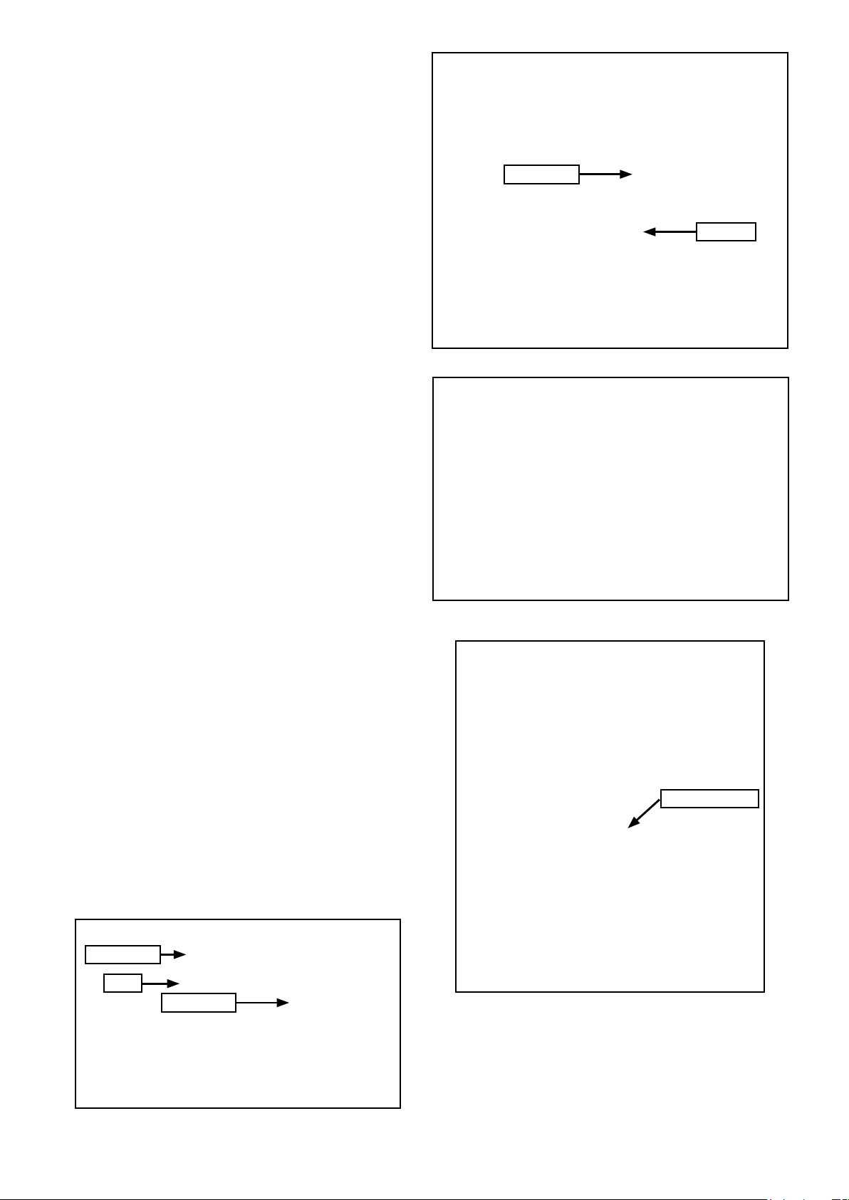
7.2.7 Connection of mains power supply
The required power supply for the heat meter is factory fitted and
terminated in a 3-way terminal block, located behind the meter
housing when the cover plate is removed. Refer to Figure 7-9.
This power supply is protected by a 1A fuse, located on the control
panel. Refer to Section 14 (Control Panel).
To connect the mains power supply to the integrator unit, use the
following procedure:
1. Unscrew the three terminals; remove the terminal block from
the three wires and discard it.
2. Pierce the cable grommet located in the lower face of the
integrator unit (below terminals L, N and
wires through.
3. Connect them to the mains power terminals in the lower right
hand corner of the integrator unit, as follows:
• Black wire – terminal L (Live)
• Blue wire – terminal N (Neutral)
• Green/Yellow wire – terminal
Refer to Figure 7-12 Integrator connection diagram.
Ensure that the wires are securely held under the metal cable
clamp.
4. Finally, re-fit the front of the integrator unit to the rear section.
Locate the four clips (two on each side of the front section)
into the corresponding openings on the two sides of the rear
section.
5. Carefully push the front onto the to rear section until it clips into
placeards to remove it from the rear section of the unit.
) and pass the three
(Earth)
Sticker seal
Wire seal
Figure 7-15: Calibration seals on flow meter
7.2.8 Security seals
Both the integrator and flow meter are supplied with factoryfitted calibration seals. These are to protect against unauthorised
tampering, manipulation or dismantling of these items that will
invalidate the product guarantee.
These seals are located as follows:
• Integrator unit - t wo stickers seals are located on the inner
(rear) face of the front section of the integrator unit. Refer to
Figure 7-14. These calibration seals must not be tampered with
or removed.
• Flow meter - t wo seals (one a sticker and the other a wire seal)
are located on the front face of the flow meter. Refer to Figure
7-15.
Following installation of the heat meter, three further user sticker
seals (supplied with the heat meter) should be applied to the
integrator unit, as follows:
• One user sticker seal must be stuck over the terminal screws
on the flow meter connections (terminals 9, 10 and 11) on the
intregrator terminal block. Refer to Figure 7-16.
• Once the front section of the integrator unit is finally fitted to the
rear section, two user sticker seals must be stuck over the joint
between the front and rear sections. These t wo stickers should
be located on the small flat area, on either side of the integrator
unit, intended for this purpose. Refer to Figure 7-17.
Figure 7-16: User sticker seal over flow meter connections
User sticker seal
Sticker seal
Ta b
Sticker seal
Figure 7-14: Calibration seals on rear of integrator front section
Figure 7-17: User sticker seal on assembled integrator unit
Section 7: Installation of Heat and Electricity Meters Page 27
 Loading...