

Page 1

MODEL NUMBER
Congratulations on the purchase of your new GRANT REVOLUTION steering wheel. This wheel is a
direct replacement for your original factory steering wheel with spoke mounted control switches. The
original airbag (SIR) module, horn switch, switch harness, switches and shroud from the factory wheel
must be removed and transferred to the new GRANT wheel.
This wheel will fit the following vehicles: (equipped with spoke mounted switches):
Cadillac – 2003-06 Escalade, Escalade EXT and Escalade ESV
(2006 is only for the old body style)
Chevrolet/GMC – 2002-09 Trailblazer/Envoy
2003-06 Silverado/Sierra Pickups and Avalanche
2003-06 Suburban/Yukon XL
2003-06 Tahoe/Yukon and Denali
2003-06 Express/Savana Vans
Hummer – 2002-06 H2
Oldsmobile – 2002-04 Bravada
These GRANT Instructions use the factory shop manual procedures for the removal and
reinstallation of the steering wheel and airbag module. In addition the GRANT instructions
include step-by- step procedures for the changeover of the switches, wiring and trim pieces from
the factory wheel to the Grant wheel. Before proceeding with the replacement of your original
steering wheel, it is necessary to read and understand all these instructions. By reading them
first, you can become familiar with the steps and terminology used. Please take note of the
following directives used throughout these instructions:
NOTICE - GRANT recommends that installation be performed by a qualified service provider such
as your local GM dealer, a certified mechanic, collision repair shop or a local airbag service
center. Many of these service centers will come to your home or place of business to change out
the air bag and wheel for a nominal fee. To find these providers check the internet for “airbag
service”, “mobile airbag service” or check the yellow pages.
CAUTION
ALWAYS WEAR SAFETY GLASSES WHEN REPAIRING OR HANDLING AN AIR BAG.
ALWAYS CARRY A LIVE AIR BAG MODULE WITH THE TRIM COVER POINTED AWAY FROM YOUR
BODY.
ALWAYS PLACE A LIVE AIR BAG MODULE ON A BENCH OR OTHER SURFA CE WITH THE TRIM
COVER FACING UP.
NEVER PROBE THE CONNECTORS ON THE AIR BAG MODULE.
AIR BAG MODULES WITH DISCOLORED OR DAMAGED COVERS OR DEPLOYMENT DOORS
MUST BE REPLACED, NOT REPAINTED.
Tools required: 3-4mm Allen Wrench T-20 and T-30 Torx Drivers
Socket Set Safety Glasses
Torque Wrench Phillips (or Flat Blade) Screwdriver
GM AIRBAG STEERING WHEEL REPLACEMENT PROCEDURES
IMPORTANT - PLEASE READ
ALWAYS CAUTION NEVER NOTICE NOTE
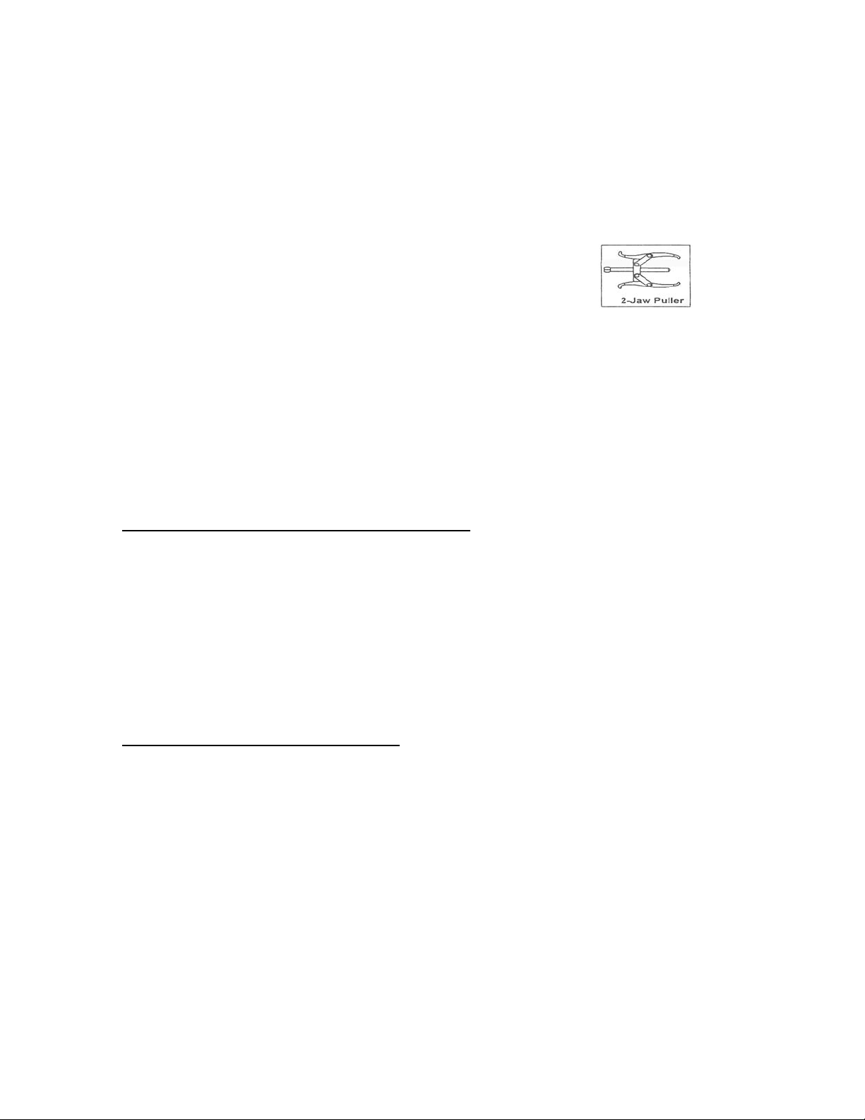
Steering Wheel Puller
Rev. 04/09 by JF
Form 97554-00-01
Page 2

DISABLING AND REMOVAL OF THE AIRBAG MODULE
1. Position the steering wheel so that it is pointed straight ahead. Write down all of your radio presets
as these may be lost when you disconnect the battery cable.
2. NOTICE - Disconnect the negative battery cable and wait at least 1 full minute for the circuit to
completely discharge before proceeding. CAUTION: Failure to fully deplete the backup power
supply could result in an accidental deployment and possible injury.
3. Using a 3-4mm (1/8”-5/32”) Allen wrench release the 2 spring fasteners by pushing inward through
the access holes. The access holes are located on both sides of the rear plastic steering wheel
shroud. See Illustration 1 below
.
Illustration 1 Illustration 2
4. Lift and partially remove the airbag module from the steering wheel in order to expose the electrical
connectors on the back side. Take care not to pull on any of the wiring. See Illustration 2 above.
5. The airbag electrical connections have a safety locking connector-position assurance (CPA) clip that
must be disconnected before you can remove the electrical connectors from the module.
6. Disconnect the electrical connectors from the airbag module.
7. Remove the airbag module from the steering wheel and place the module face up on the floor, seat
or work bench. If you carry the module make sure the trim cover is pointed AWAY from your body.
REMOVING THE STEERING WHEEL FROM THE VEHICLE
1. Remove the horn plunger by pressing inward to the stop and rotating the plunger 90° to the left then
pulling out. See Illustration 3 below.
Illustration 3 Illustration 4
Page 3
2. Remove the horn switch assembly by loosening the 4 T-30 Torx screws (numbers 1 and 4) holding
the contact plates to the steering wheel and remove this entire mechanism (2) from the wheel. Note
orientation (wires at the top of the switch mechanism) so you do not reinstall upside down. See
Illustration 4 above.
3. Disconnect the wheel switch wiring harness at the column connector. Do not pull excessively on
the connector or clockspring mechanism and do not turn the clockspring now or at any time
during the remainder of the installation.
4. Remove the steering wheel retainer nut and mark the shaft and wheel for alignment.
5. Remove the steering wheel by using the GM J1859-A puller with the
J-36541-A adapter and J42578 puller legs. Or an equivalent 2 jaw
bearing type puller (see illustration).
6. Remove the rear plastic shroud by removing the 2 T-20 Torx screws in the back of the wheel.
7. Loosen the wiring harness from around the hub of the wheel to get enough slack to remove the
switches. Push each switch out of the wheel slightly by inserting a narrow flat blade or Phillips
screwdriver into the rear hole in each spoke and push the switch out the front of the wheel. Push
slowly and evenly and do not stab at the switch or you may damage it. When the switch is clear of
the wheel disconnect the wiring harness from it and remove the switch.
8. Remove the switch wiring harness from the original wheel by pulling the switch connectors back
through the hole in each spoke and removing the plastic clip from the wheel center.
PREPARING NEW WHEEL FOR INSTALLATION
1. Reinstall the switch wiring harness from step 8 above in the same orientation as it came out.
2. Reinstall the plastic shroud with the screws previously removed in step 5 above.
4. Push the leads from the wiring harness up through the hole in each spoke so the plug end that goes
onto each switch is protruding out of the switch hole in the front of the wheel.
5. Connect the wiring to each switch and push the switch back into the new wheel in the same location
as the old wheel. Take up the slack in the wiring by pulling it back through the access hole while
pushing the switches in.
INSTALLING NEW STEERING WHEEL
1. Position the new wheel onto the shaft orienting it to the mark made earlier. (Reference wheel
removal step number 4 above).
2. Install the steering wheel retainer nut and torque to 40 N-m (29 lb ft).
3. Reinstall the horn plunger into the plastic tube by pushing down until the stop and rotating 90° to the
right to lock it into position.
4. Reinstall the horn switch assembly by positioning onto wheel and tightening the 4 Torx screws
securely (make sure wires are at the “top” of the switch mechanism).
5. Position the airbag module near the wheel and connect the electrical connectors to the module.
6. Connect the connector-position assurance (CPA) clips into the electrical connectors. Seat and lock
the connections.
Page 4
7. Position the alignment posts of the airbag module to align with the holes that are located on the
steering wheel housing.
8. Push the airbag module into the steering wheel to engage and latch the 2 spring fasteners. Once
positioned pull up on the sides of the airbag module to ensure that both spring fasteners are fully
engaged.
9. Reconnect the negative battery cable. NOTE: When the ignition switch is turned to the “ON”
position the air bag indicator light should flash then turn off. If the light does not flash or remains on
there is a problem with the connections that must be resolved. Refer to “Disabling and Removal of
the SIR (Airbag) Module” instructions for removal and steps 6 and 7 above for connections of the air
bag wiring.
Remember to reset your radio station presets and clock and enjoy your new GRANT REVOLUTION
steering wheel. When you first start the vehicle the engine may run less smoothly than before as the
computer will have to reset itself due to the power loss but this will just take a moment or two.
If you need further assistance contact GRANT Technical Service Support at:
Phone (626) 305-0700 Fax (626) 305-0799
Email: [email protected]
Support Hours are 8:00AM to 5:00PM Pacific Time
Monday through Friday
We warrant this product for ninety (90) days from the date of original purchase to be free from defects in materials and workmanship. If, during
this period, the product fails under normal usage because of a manufacturing defect, then we will replace or repair the item. To obtain repair or
replacement under the terms of this warranty, notify us at 615 Elca Lane., Brownsville, TX 78521. Proof of purchase and date of purchase are
All implied warranties, including warranty of merchantability, are limited to this same ninety-day period from date of original
purchase. We are not liable for any direct or consequential loss of property damage arising from any use of this product. This
warranty gives you specific legal rights, and you may also have other rights which vary from state to state. Offer good in U.S.A. and
OUR LIMITED WARRANTY
required to validate warranty.
Canada only.
GRANT PRODUCTS INTERNATIONAL, INC.
615 Elca Lane
Brownsville, TX 78521
On the Web: www.grantproducts.
Rev. 04/09 by JF Form 97554-00-01
com
 Loading...