

1. Point wheels straight ahead and disconnect battery or pull
horn fuse before starting removal of the old wheel so horn
won’t short out and blow during installation.
2. Remove horn mechanism. This is normally done by one
or more of the following steps:
a) Press down on horn cap or ring and turn.
b) Remove emblem cap from its snapped-in condition by
grasping it and pulling toward you or pry loose.
c) Horn Ring and emblem may be secured by screws
which are concealed in rear side of wheel spokes.
If one of the above operations has n ot removed all of the
horn parts, it will have exposed the remaining screws to
permit easy removal of the balance of such parts.
3. Remove nut which holds wheel to shaft.
4. Mark shaft as to which is the top of the wheel.
5. With conventional pull er (or GRANT puller 5891), use the
two tapped holes which you will find in the hub of old
wheel to pull off the steering shaft.
If a puller is not available, you may improvise an efficient
one to do the job. By drilling two holes of the proper size in
a short steel bar and using two screws of the proper
length you can tighten them and pull the ol d wheel very
easily.
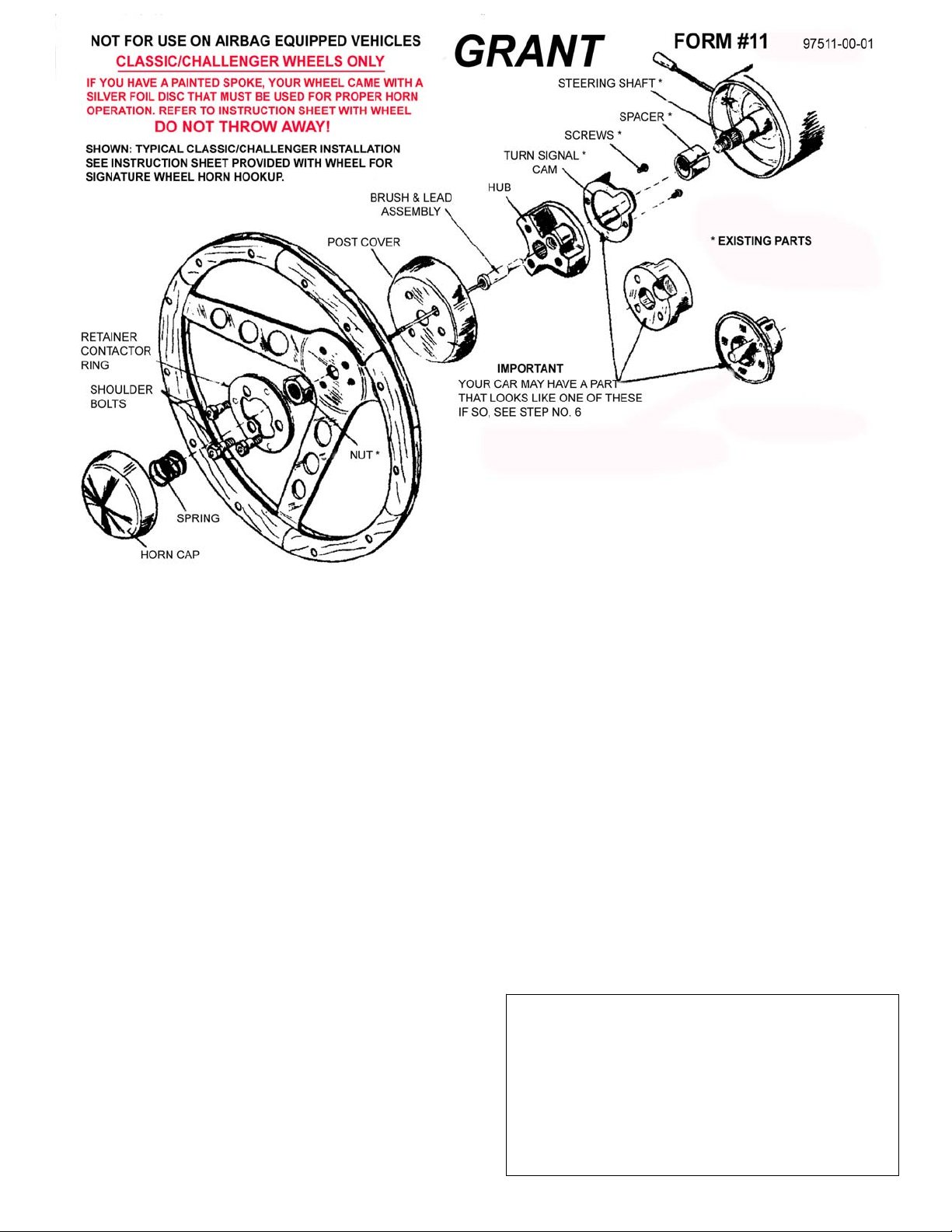
6. If there is a turn signal cancellation device, such as
illustrated in diagram, attached to the back of your old
steering wheel, remove this part and reinstall it orienting
the post to approximately the 2 o’clock position to go
through the hole in custom hub.
On the Web: www.grantproducts.com
Rev. 5/09 by J.F.
7. Remove the metal probe from the signal contact tube,
retaining both the spring and the holding sleeve. Thread
the “T” ended wire through the spring and the sleeve.
Place them in the contact tube so that the “T” is making
the electrical contact at the bottom of the tube and is held
down by the spring, which is held i n place by the sleeve
located back in it’s original position.
8. Position custom hub on splined shaft, observing that “top”
is located in accordance with mark you made in step 4.
9. Position post cover and wheel on hub, threading the wire
lead through appropriate holes. Use the three shoulder
bolts provided, but do not tighten at this time.
10. Check to see if wheel is in the proper position, and if
correct, install the wheel retainer nut and tighten securely.
11. Remove shoulder bolts and reinstall same through
retainer contactor ring so that the fiber side is toward
you. Tighten shoulder bolts, see torque setting below.
12. Connect wire lead to retainer contactor ring. Position
spring on nut, you may find tape a help. Place horn ca p in
position by aligning dimples in cap with reliefs in fiber
material and push until the dimples pass the fiber. Turn
cap left or right until tight (1/4-1/2”).
13. Reconnect battery or replace horn fuse and enjoy your
new GRANT wheel.
SHOULDER BOLTS 10-12 FT/LBS
STEERING SHAFT NUT 25-30 FT/LBS
We warrant this product for ninety (90) days from the date of original purchase to be free
from defects in materials and workmanship. If, during this period, the product fails under
normal usage because of a manufacturing defect, then we will replace or repair the item.
To obtain repair or replacement under the terms of this warranty, notify us at 615 Elca
Lane, Suite C, Brownsville, TX 75821. Proof of purchase and date of purchase are
required to validate warranty.
All implied warranties, including warranty of merchantability, are limited to this same
ninety-day period from date of original purchase. We are not liable for any direct or
consequential loss or property damage arising from any use of this product. This
warranty gives you specific legal rights, and you may also have other rights which vary
from state to state. Offer good in U.S.A. and Canada only.
FOR YOUR OWN SAFETY, DO NOT USE THIS WHEEL FOR ANY COMPETITIVE OR
COMMERCIAL RACING PURPOSES: RACING DOES NOT CONSTITUTE NORMAL
TORQUE REQUIREMENTS
Our Limited Warranty
IMPORTANT
 Loading...