

Granite Audio Ground zero Owners manual
GROUND ZERO WORKSHEET INSTRUCTIONS.
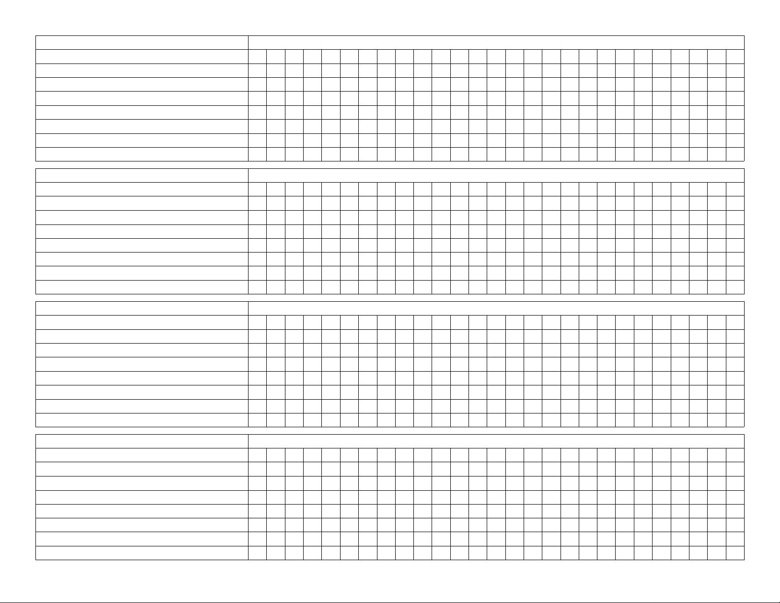
Use this worksheet to keep track of the switch positions you try and the corresponding noise level at each
position. Under the Connected Components column
make a list of which of your components are connected to which switch group; SW1, SW2, or SW3. In
the Wall Outlet Cable row write which Switch group
this cable is connected to. The Misc. Variable row is
for you to add your own variable condition. In the
Noise Measurement row you will note the noise reading for the corresponding switch and cable positions.
Ground Zero will let you test dozens of different impedance positions in minutes, while other methods
would take days to do this many tests.
You will probably get different noise measurements by
moving the wall outlet cable to different wall outlets
and by connecting it to different switch groups. In
some systems the wall outlet cable may not give any
variation in the noise. The use of this cable is optional. We do highly recommend using the wall outlet
cable if you are also using “cheater plugs” or any other
power cord or device that defeats the chassis ground
of any individual component in your system. We also
recommend it if you are using a 3-prong power cord
that has the ground pin removed. The wall outlet
cable can be connected to various different available
wall outlets to change the ground impedance of the
system. The wall outlet cable allows you to change
the ground impedance without removing the ground
connection. Use the wall outlet that gives you the
lowest noise reading.
Ground Zero can quickly lower your
noise floor and ground loop hum in a
few minutes. But, to get the absolute
lowest possible noise floor from the
Ground Zero system, you will need to
devote some more time and patience
to work through all the possible
switch and cable positions. You can
also experiment with connecting the
Ground Zero component cables to different switch
groups. This worksheet has several tables so that you
can try as many combinations as you have time and
patience for. The Ground Zero is a universal ground
loop hunter and it will find your ground loop and give
you the lowest possible noise floor when you get the
optimum switch and cable positions. Before you install
Ground Zero take a base noise measurement reading
to give you a reference point to measure your further
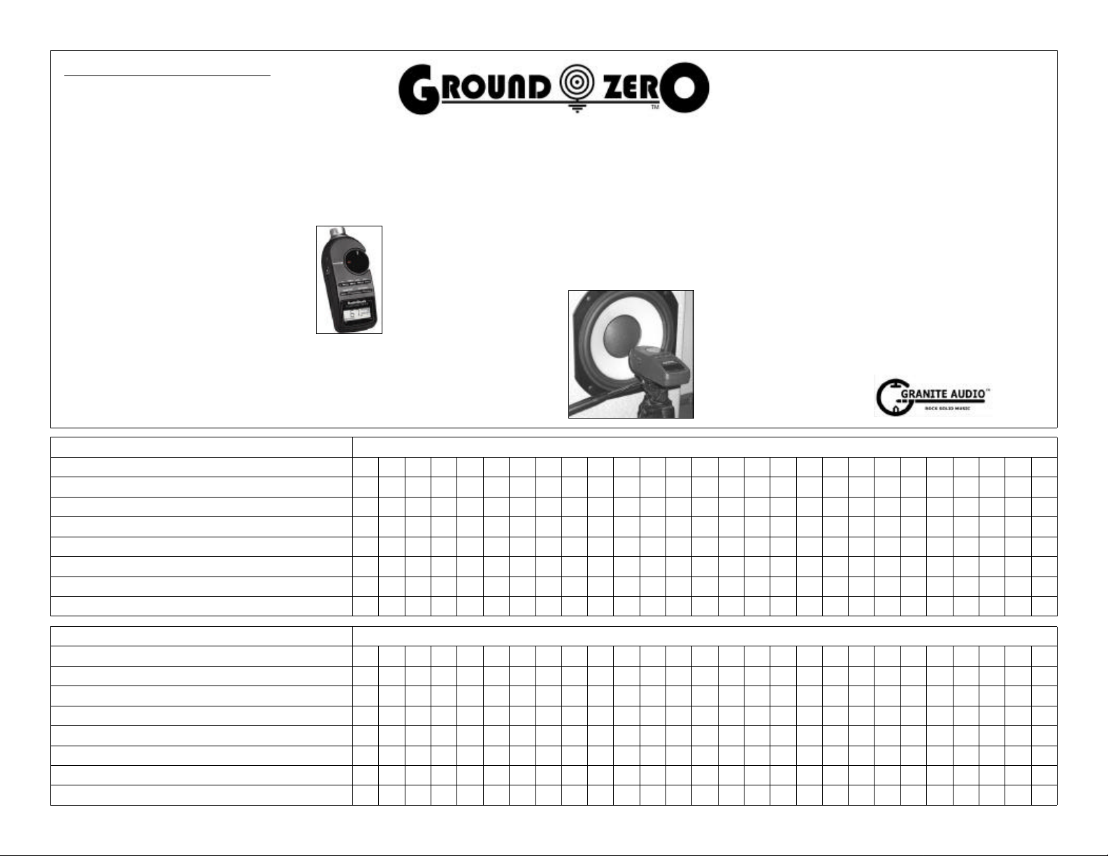
test results against. You can use your ears to evaluate your noise test results. But, we recommend you
use a Radio Shack SPL meter, or any other brand of
meter, for better objective results.
Mount the SPL meter on a camera tripod and place
the microphone close to the woofer cone of your
speaker, as shown in the photo below. The Radio
Shack digital model is nice because it gives you a
digital number to write
in on this worksheet.
It’s just faster and
simpler. More advanced technicians
can use an accurate
AC voltmeter and
measure the noise
level right at the
speaker terminals with
an electrical type decibel meter, rather than an SPL
decibel meter. Your portable Radio Shack AC voltmeter will not have a low enough residual noise floor for
this option. You will need something that can measure
AC voltage down into the microvolts range below
0.001 volts AC. This type of meter will allow measurements below the threshold of the Radio Shack SPL
meters. The Hewlett Packard Model 400E or 400EL
decibel meter works good for this and can be found
used on Ebay for $20 to $70. But, these require a little
more knowledge to use and the right cables & adapters to connect to your speaker terminals. This HP
meter would not be for beginners.
Ground Zero is designed to eliminate ground loop hum
and other noise that is a result of poor grounding or
ground impedance differential. It will not get rid of
noise from other causes such as tape hiss, tube hiss,
thermal noises, mechanical noises, fan noises, internal
component noise, or motor noise.
All contents of this worksheet copyright 2004
by Granite Audio with all rights reserved.
CONNECTED COMPONENTS SWITCH GROUP
POWER SW1 H H H H H H H H H M M M M M M
PREAMP SW2 H M L L M L H M H H M L L M L
SOURCE SW3 H M L M L H L H M H M L M L H
(GREEN TIP) WALL OUTLET CABLE
MISC. VARIABLE
MISC. VARIABLE
BASE= LEFT CHANNEL NOISE MEASUREMENT
BASE= RIGHT CHANNEL NOISE MEASUREMENT
CONNECTED COMPONENTS SWITCH GROUP
POWER SW1 H H H H H H H H H M M M M M M
PREAMP SW2 H M L L M L H M H H M L L M L
SOURCE SW3 H M L M L H L H M H M L M L H
(GREEN TIP) WALL OUTLET CABLE
MISC. VARIABLE
MISC. VARIABLE
BASE= LEFT CHANNEL NOISE MEASUREMENT
BASE= RIGHT CHANNEL NOISE MEASUREMENT
SWITCH POSITIONS ( H = HIGH M = MEDIUM L = LOW )
M M M L L L
H M H H M L
L H M H M L
SWITCH POSITIONS ( H = HIGH M = MEDIUM L = LOW )
M M M L L L
H M H H M L
L H M H M L
L L L L L L
L M L H M H
M L H L H M
L L L L L L
L M L H M H
M L H L H M
CONNECTED COMPONENTS SWITCH GROUP
POWER SW1 H H H H H H H H H M M M M M M
PREAMP SW2 H M L L M L H M H H M L L M L
SOURCE SW3 H M L M L H L H M H M L M L H
(GREEN TIP) WALL OUTLET CABLE
MISC. VARIABLE
SWITCH POSITIONS
M M M L L L
H M H H M L
L H M H M L
L L L L L L
L M L H M H
M L H L H M
MISC. VARIABLE
BASE= LEFT CHANNEL NOISE MEASUREMENT
BASE= RIGHT CHANNEL NOISE MEASUREMENT
CONNECTED COMPONENTS SWITCH GROUP
SWITCH POSITIONS
POWER SW1 H H H H H H H H H M M M M M M
PREAMP SW2 H M L L M L H M H H M L L M L
SOURCE SW3 H M L M L H L H M H M L M L H
(GREEN TIP) WALL OUTLET CABLE
MISC. VARIABLE
M M M L L L
H M H H M L
L H M H M L
L L L L L L
L M L H M H
M L H L H M
MISC. VARIABLE
BASE= LEFT CHANNEL NOISE MEASUREMENT
BASE= RIGHT CHANNEL NOISE MEASUREMENT
 Loading...