

Grange Fencing VALENCIA CORNER ARBOUR, VALCORARB Assembly Instructions Manual

VALENCIA
CORNER
ARBOUR
WITH TABLE
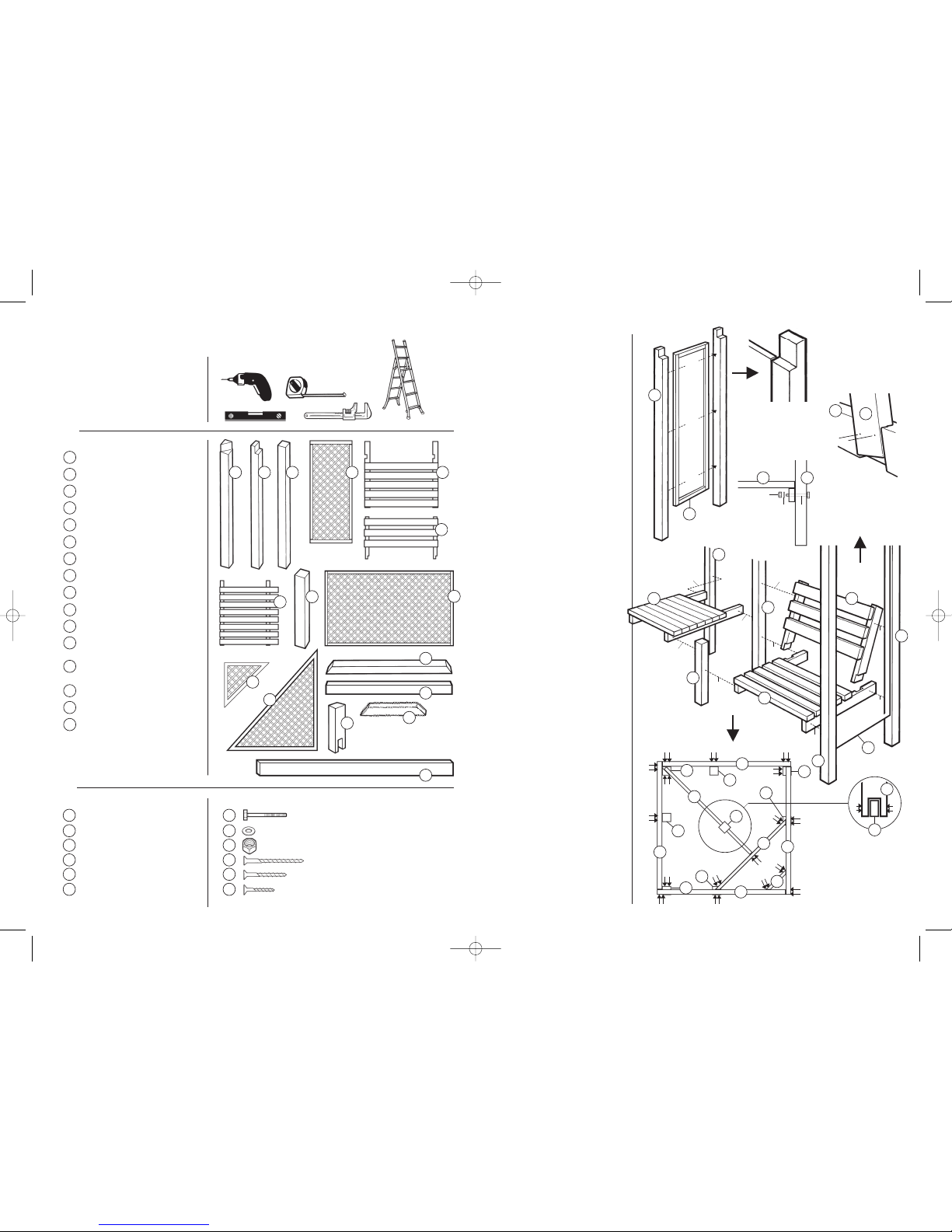
ASSEMBLY INSTRUCTIONS
S
TEP 4
Create roof support / rear corner
post.
Fix 1x Roof Beam (R) to the front
r
ight hand side assembly ensuring
f
lush with post (
B)
. Follow around the
structure until square (note: post
joints are offset as
Fig.4), using 18x
(
x) fixing Back Corner Post (A) with
r
ight angle cut facing front.
F
ix Front Support Beam (
M)
using 4x
(
x)
and then Corner Support Beam
(
N)
using 4x (x). Finally, add the
Support Strut (
P) to the front using
a
nother 4x (
x)
as in Fig.4
.
Note: the roof support strut can now
be added, (measuring the centre
between corner to corner), using 4x
(
z). However, do not tighten just yet.
STEP 5
Fix back panels, table and corner
supports.
Fix the Table Top (G) using 4x (x)
ensuring square and level. Fix the four
Large Back Trellis Panels (
J) using 6x
(
x) for each panel as Fig.5.
Note: keep the panels front edge at
the front of the structure. Fix the two
Corner Supports (
K) using 4x (y) in
each suppor
t as
Fig.9.
STEP 6
Roof sections.
Fix the Roof Sections (L) together in
pairs making 4 equal roof sections
using 2x (
z) in each pair. Position the
roof sections on the roof, resting on
Roof Vertical Support (
Q) and
levelling off around the roof (it is
recommended to tie roof sections
together at this time using some
string).
Once all of the sections are level, fix
the roof using screws (
x) x16. Untie
the roof sections and check all fixings
are tight and secure.
The structure is now complete.
PLAN
GRANGE FENCING LIMITED
Halesfield 21, Telford TF7 4PA
Tel: 01952 588088 Fax: 01952 581522
Email: sales@grangefen.co.uk Web: www
.grangefen.co.uk
OUT OF HOURS MESSAGE SERVICE: 01952 588088
DECEMBER 2012 - ISSUE 3
ALL PRODUCTS ARE MEASURED TO
THE HIGHEST AND WIDEST POINT AND
ALL SIZES ARE APPROXIMATE
T
o ensur
e longevity of your str
uctur
e it is r
ecommended that it is tr
eated with a wood pr
eservative on a yearly basis.
Tie at
corners
AFTERCARE
VALENCIA CORNER ARBOUR (VALCORARB)
2.3m
2m sq.
2m sq.
Grange Code: V
ALCORARB
A
J
L
L
L
M
N
R
Fig.5
Fig.6
Fig.7
Fig.8
Fig.9
A
N
R
R
B
B
C
K
P
M
Q
y
x
x
x
y
y
x
x
x
zz
y
y
y
y
y
y
y
y
y
y
y
Valencia Corner Arbour (Assembly) 13/12/12 10:31 Page 1
T
hank you for choosing this garden structure from Grange Fencing Ltd. In order to
gain the most benefit from it please read the following instructions carefully.
PARTS LIST
BACK CORNER POST x 1
S
IDE SUPPORT POSTS x 4
SEAT SUPPORT POSTS x 2
SMALL TRELLIS PANELS x 2
SEAT BASE x 2
SEAT BACK x 2
TABLE TOP x 1
TABLE LEG/SEAT SUPPORT x 1
LARGE TRELLIS PANELS x 4
CORNER SUPPORTS x 2
ROOF QUADRANTS x 8
FRONT ROOF
SUPPORT BEAM x 1
CORNER ROOF
SUPPORT BEAM x 1
SUPPORT STRUT x 1
VERTICAL ROOF SUPPORT x 1
SIDE WALL ROOF BEAMS x 4
P
OWER DRILL/SCREWDRIVER
with posidrive No.2 bit
3mm Pilot Drill
ADJUSTABLE SPANNER
T
APE MEASURE
S
TEPLADDER
S
PIRIT LEVEL
B
EFORE YOU START
• Please check the packs and
m
ake sure that you have all
o
f the parts listed. If not,
contact your retailer who will
be able to help you.
When you are ready to start
m
ake sure you have the right
t
ools to hand, plenty of space
and a clear dry area for
assembly.
• It is advisable for two people
t
o carry out the work.
A
SSEMBLY INSTRUCTIONS
STEP 1
Create the side assemblies.
Take the Side Trellis Panels (D)
and affix to Side Support Posts
(
B) using fixings (y) x6 (ensure
that the trellis is flush with the
outside edge as
Fig.1)
Repeat for second side assembly.
STEP 2
Make the seats.
Take Seat Base (E) and fix Seat
Back (
F) inserting in the slots and
fixing using 2x (
z) for each insert
(see
Fig.2).
Repeat for the second seat.
STEP 3
Fix seats to sides and to table
support.
Ensure work area is flat - lay seat
on back and fix side assembly
using Coach Bolts (
t) through
pre-drilled holes. Add Washer (
v)
and Nut (
w) and fix hand tight
(ensure the bolts are fitted
outside in).
Now lay seat support post on the
opposite side and fix with coach
bolt, washer and nut through predrilled hole. Ensure all is square
and fix seat back top to side and
seat support sections using 1x (
x)
each side.
Repeat for second section and
now these will stand alone.
Position so two seat sections can
be joined via the T
able Leg/Seat
Support (
H) using the last two
coach bolts, washers and nuts,
again hand tight (note: the holes
in the table leg are offset), tighten
all nuts.
Fig.1
t
z
z
x
x
x
x
xx
x
Fig.4
A
B
C
D
E
F
G
H
J
K
L
M
N
P
Q
R
A B C D E
F
G
B
BE
H
J
L
M
Q
P
R
M
N
R
R
R
R
v
w
C
C
P
xx
xx
x
x
x
x
x
x
x
x
xx
x
x
x
xx
xx
x
x
x
x
x
HARDW
ARE P
ACK
COACH BOLTS - 8 x 120mm x 8
WASHERS x 8
NUTS x 8
SCREW - 4 x 60mm
x74
SCREW - 3.5 x 45mm x24
SCREW - 3.5 x 35mm x20
t
v
w
x
y
z
t
v
w
x
y
z
x
K
T
OOLS REQUIRED(Not Supplied)
T
rellis panel (
D)
s
hould be flush
w
ith Post (
B)
cut-out
Fix Seat (E) to
assembled side
section with
coach bolts (
t)
Offset holes
for bolts in
table leg
Seat Backs (
F) slot
into Seat (E) notches.
Fix with screws (z)
PLAN VIEW
Create beam structure
(
Beams R, N, M & P)
ar
ound the assembled
Posts (A, B & C).
N
D
A
B
B
C
E
E
F
F
G
H
D
Fig.2
A
B
B
y
y
y
y
y
y
Fig.3
x
x
x
x
x
t
t
t
t
B
Q
Q
B
N
x
x
x
x
Valencia Corner Arbour (Assembly) 13/12/12 10:31 Page 2
 Loading...