

Page 1
DOMED
PERGOLA
ASSEMBLY INSTRUCTIONS
TOP ELEVATION
SIDE ELEV
ATION
3.28m
2.89m
1.35m
3.8m
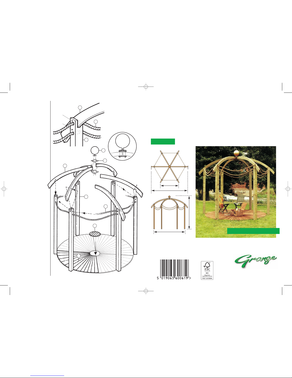
STEP 9
F
it the 2nd Metal Plate onto
t
he opposite side of the
C
urved Beams at the centre.
S
TEP 10
T
hread one of the Ropes (
5)
through the Posts and
Curved Beams. The two
e
nds should be brought
t
ogether in one of the holes
and retained by screws.
Evenly space the Rope
between the Posts.
STEP 11
Fit the 2nd Rope in the
s
ame manner through the
C
urved Beam holes.
STEP 12
Ensure the structure is
vertical and the Posts are all
at the same height. Fill the
holes with the chosen
method.
STEP 13
Lay the Fan Deck Tiles (3)
and centre Round Tile (
4).
OPTION:
If your Pergola has a Golden
Globe (
6) to fit on the top,
this may now be fitted.
1
1
x
2
4
5
5
2
y
y
3
SECURE THE ROPE
E
NDS WITHIN THE
HOLES OF ONE OF
THE POSTS USING
S
CREWS (Y) AS
INDICATED
THE GLOBE IS FIXED
I
NTO THE CENTRE
OF THE METAL
SUPPOR
T
PLATE
6
yy
PLAN
THE DOMED PERGOLA (JFDPG)
JULY 2011 - ISSUE 2
GRANGE FENCING LIMITED
Halesfield 21, Telford TF7 4PA
Tel: 01952 588088 Fax: 01952 581522
Email: [email protected] Web: www.grangefen.co.uk
OUT OF HOURS MESSAGE SERVICE: 01952 588088
ALL PRODUCTS ARE
MEASURED TO THE HIGHEST
AND WIDEST POINT AND ALL
SIZES ARE APPROXIMATE
To ensure longevity of your
structure it is recommended
that it is treated with a
wood preservative on a
yearly basis.
AFTERCARE
Grange Code: JFDPG
Dome Pergola Inst 8/7/11 10:01 Page 1
Page 2
Thank you for choosing this garden structure from Grange Fencing Ltd. In order to gain the most
b
enefit from it please read the following instructions carefully.
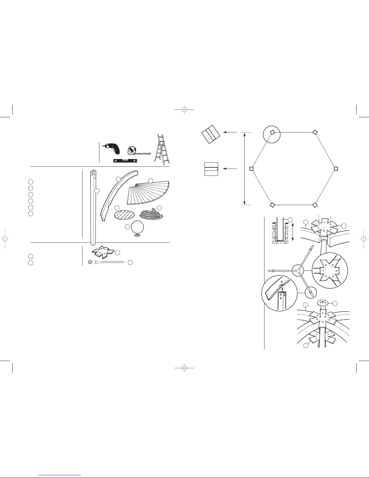
TOOLS REQUIRED (Not Supplied)
P
OWER DRILL (+ crosshead screwdriver bit)
S
PIRIT LEVEL
T
APE MEASURE
S
TEPLADDER
P
ARTS LIST
T
IMBER POSTS 6
C
URVED BEAMS 6
ELITE FAN DECKING TILE 4
ELITE ROUND DECK TILE 1
SISAL ROPES 2
GOLD GLOBE 1
HARDWARE PACK
METAL SUPPORT PLATES 2
SCREWS (No.8 x 50) 28
ASSEMBLY INSTRUCTIONS
STEP 1
Using the layout shown (above) mark out the
area where the structure is to be sited. The
ground should be flat and level for the Fan Tiles.
STEP 2
Prepare the holes for the Posts (1). Each hole
should be 300mm deep. Make sure the depths
are the same to ensure the pergola is level when
all the posts are sited. Allow adequate room for
the preferred method of fixing (ie. MetCrete).
We would recommend that you use
MetCrete,
fast set post fixing concrete to fix your posts.
Easy to use, it sets in just 10 minutes.
STEP 3
Take one of the Metal Plates (x) for the centre
of the roof. Fasten one of the Curved Beams (
2)
to it using screws (
y).
STEP 4
Fasten two of the other Curved Beams to the
Metal Plate missing one spur out each time.
STEP 5
Place three Posts in the holes corresponding
with the Curved Beam assembly.
STEP 6
Raise the Cur
ved Beam assembly and locate
into the top of the Posts.
STEP 7
Fix another Curved Beam to the Metal Centre
Plate. Site another Post in the corresponding
hole and locate the Cur
ved Beam in the slot.
STEP 8
Repeat step 7 for the r
emaining two Cur
ved
Beams and Posts.
(continued overleaf)
BEFORE YOU START
• Please ensure that you check all the component parts for quantity and quality before you
commence building the product. Report any missing parts immediately. The manufacturer will
not accept any responsibility for damaged items once any part of the product has been fitted or
altered in any way.
• Timber is a natural material and will react to varying levels of moisture content - ie. will swell or
shrink. All of the T
imber components ar
e pr
essur
e treated green. However, should extra
protection be required, they should be treated using a wood preservative treatment, following the
manufacturers instructions.
HEALTH AND SAFETY
Do not lean or stand on the r
oof assembly at any time - the str
uctur
e is not of a load bearing design.
Do not overstr
etch when working fr
om the step ladder
.
In order to reduce the risk of suffocation please keep all plastic bags and small parts away from children.
• When you ar
e r
eady to star
t, make sur
e you have the right tools to hand, plenty of space and a
clean, dry area for assembly. It is advisable for two people to carry out the work.
1
2
3
4
5
6
x
y
x
y
2.89m
300mm
DOMED PERGOLA
P
OST PLAN
Note: ensure correct
orientation of posts
a
round the ‘hexagon’.
AB
CD
1
6
2
yy
y
x
STEP 2
1
2
3
4
5
6
ESTABLISH THE
STRUCTURE WITH
THREE POSTS AND
CUR
VED BEAMS
LINKED WITH THE
METAL CENTRE
PLATE.
2x 5mm CLEARANCE
HOLES WILL NEED
TO BE DRILLED IN
THE METAL PLATE
TO ALLOW THE
GLOBE BRACKET
(6) TO BE FITTED.
2
x
Dome Pergola Inst 8/7/11 10:01 Page 2
 Loading...