

To ensure longevity of your structure it is recommended that it is treated with a wood preservative on a yearly basis.
AFTERCARE
POSTS
TRELLIS SECTIONS
SEAT BACK
SEAT
BACK LATTICE PANEL
ROOF BEAMS
LONG ROOF SECTION
S
HORT ROOF SECTION
R
OOF SUPPORT
FINIAL
A
D
E
B
C
G
H
J
K
F
A
D
E
B
C
G
J
F
F
K
K
H
Fig.9.Fig.8.
x
z
A
A
C
E
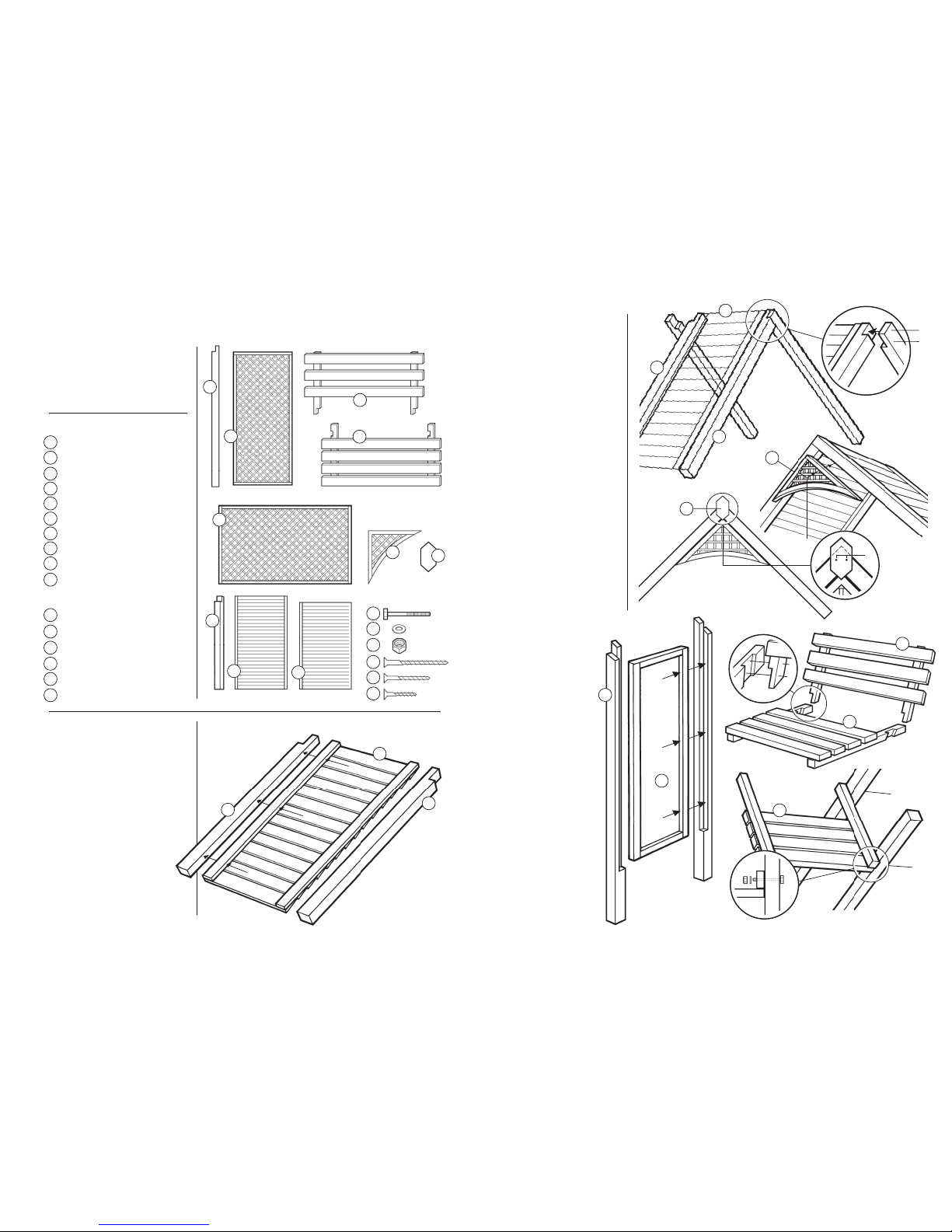
STEP 5
When bolted sides are fitted, stand the
a
ssembly upright.
F
ix the back of the seat to the posts of
the side sections
as in
Fig.8.
S
TEP 6
N
ow fix the Back Lattice (E)above the
seat back using two screws (
z) either
s
ide. See
F
ig.9
.
FINALLY..
Fix the side sections to the roof
assembly using screws (
x) as shown
below, ensuring that the roof is centred
and lined up evenly upon your arbour.
A
x
x
==
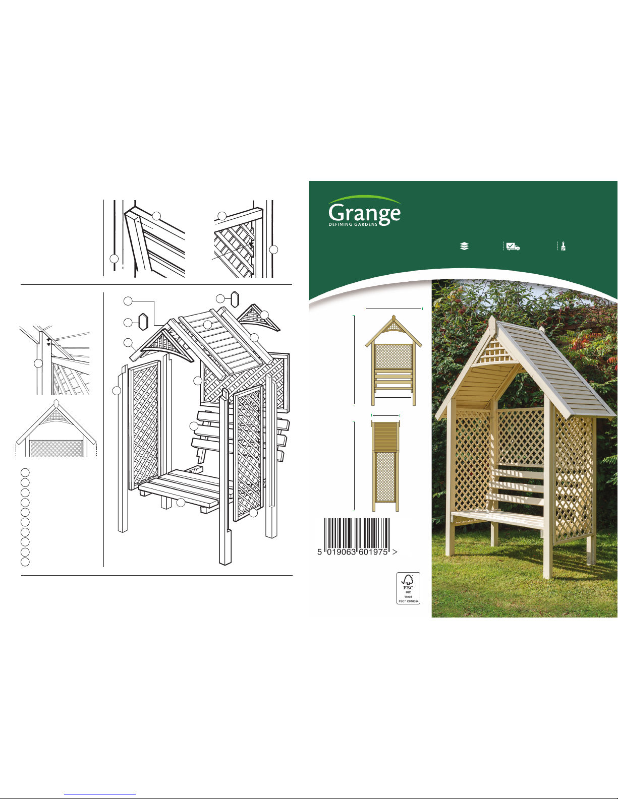
VALARB - 274cm [H] x 174cm [W] x 74cm [D]
VALENCIA ARBOUR
Self-Assembly required Home Delivery available Pre-Painted available
www.grangefen.co.uk
All products and related emblems featured are
trademarks of Grange Fencing Ltd.
©2015 Grange Fencing Ltd All rights reserved.
In line with the Company’s policy of
continuous product development, the right
is reserved to change and improve product
design without prior notice.
VALENCIAARBOUR SHOWNHERE PRE-PAINTED
WITHTHE CORNISHCREAM COLOUROPTION
CODE: VALARB
PLAN
274cm
174cm
74cm
120cm
274cm
BEFORE YOU START
When you are ready to start make sure you
have the right tools to hand, plenty of space
and a clean dry area for assembly.
I
t is advisable for two people to carry
out the work.
Drill pilot holes to aid assembly.
Please check the packs and make sure that
you have all of the parts listed above. If not,
contact your retailer who will be able to help
you.
ASSEMBLY
STEP 1
A
s
s
emble the Roof Sections
(
F toG - F toH) w
i
t
h s
c
rews (
y)
as shown in
Fig.1.
Thank you for choosing this garden structure from Grange. In order to gain the most
benefit from it please read the following instructions carefully.
T
OOLS REQUIRED(Not Supplied)
P
OWER DRILL/SCREWDRIVER
w
ith posidrive No.2 bit
3
mm DRILL FOR PILOT HOLES
ADJUSTABLE SPANNER
P
ARTS LIST
POSTS x 4
TRELLIS SECTIONS x 2
SEAT BACK x 1
SEAT x 1
BACK LATTICE PANEL x 1
ROOF BEAMS x 4
LONG ROOF SECTION x1
SHORTER ROOF SECTION x 1
ROOF SUPPORT x 2
FINIAL x 2
HARDWARE PACK
BOLTS - 8 x 120 x 4
WASH ERS x 4
NUTS x 4
SCREW - 4 x 6cm x10
SCREW - 3.5 x 4.5cm x30
SCREW - 3.5 x 3.5cm x12
A
u
v
w
x
y
z
x
y
z
u
v
w
D
E
A
B
G
H
C
D
E
J
K
Fig.1.
Fig.2.
Fig.3.
Fig.4.
Fig.6.
z
z
Fig.7.
Fig.5.
A
SSEMBLY(cont.)
S
TEP 1 (cont.)
Fix together the two Roof
assemblies (
F/G & F/H) as shown in
F
ig.2.using screws (z). The one
r
oof section is slightly longer than
the other to allow them to be fixed
together.
Fix the Roof Supports (
J) to the roof
a
ssembly front and back as shown in
F
ig.3.using two screws (y)each
s
ide.
Finally, fit the finials (
K) front and
back to the roof using two screws
(
z). See Fig.4.
This completes assembly of your
arbour roof.
STEP 2
Assemble the Side Sections
(
A to B) as shown in Fig.5. using
screws (
y).
STEP 3
Assemble the seat (C & D)
as shown in
Fig.6. Use two screws
(
z) either side.
STEP 4
Bolt the assembled side sections to
the seat as shown in
Fig.7.
A
s
s
e
mb
ly
instructions
continued overleaf...
y
y
y
y
B
C
G
H
J
K
F
F
F
G
y
y
y
u
u
A
B
C
J
D
D
u
v
w
K
z
F
F
F
G
z
z
 Loading...