

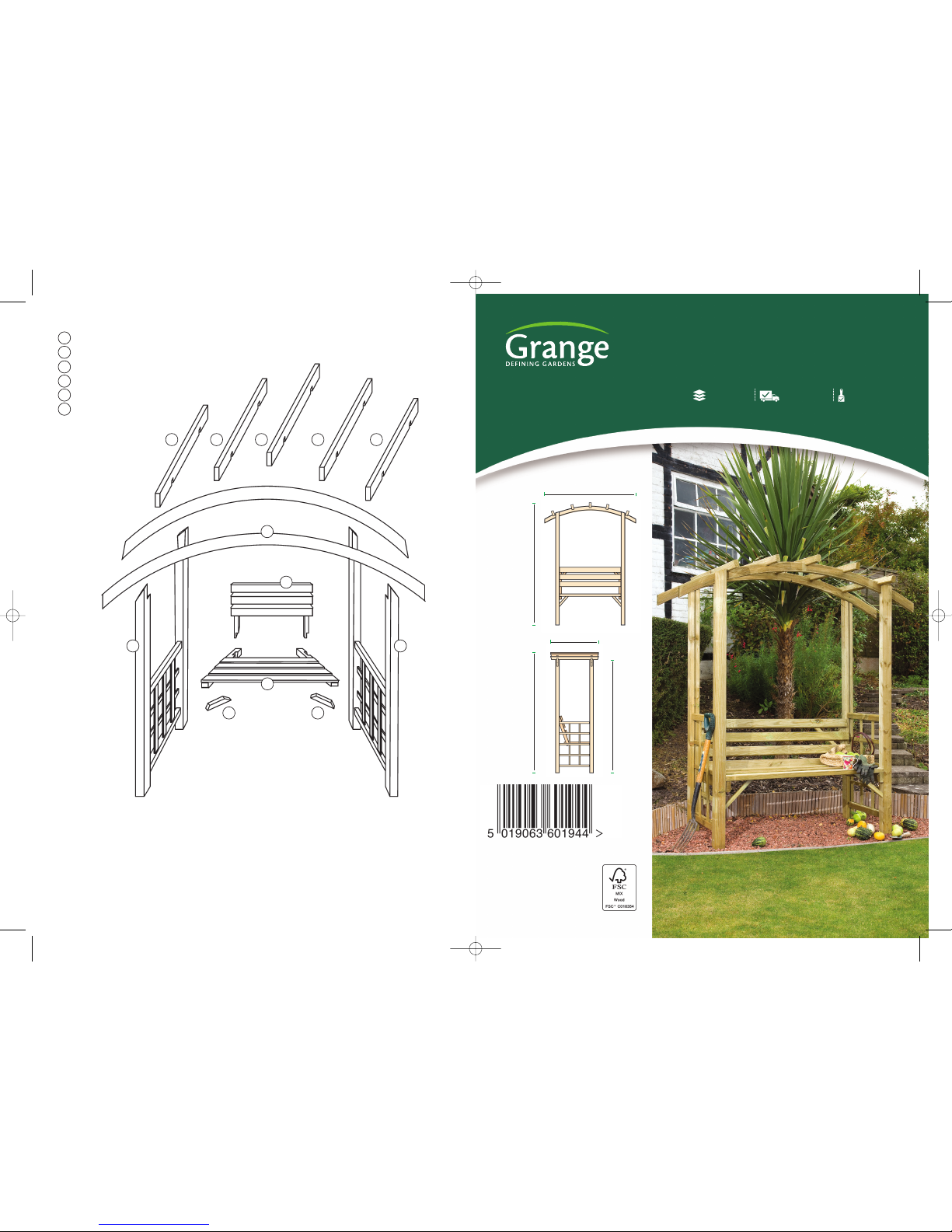
Grange Romana Arbour, ROMARB Assembly Instructions Manual
D
E E E E E
B
FF
A
A
C
CARE OF YOUR ARBOUR
The Romana Arbour is made of planed pressure treated and FSC certified timber
and as such is guaranteed against rot for a minimum of 15 years. However, it
should be remembered that as a natural product, timber is subject to movement
and weathering as it seasons. It is not uncommon for small spits to occur when
drying and warping when timber is allowed to dry too rapidly. These will normally
go back when humidity rises, it is nature at work and not considered a fault.
AFTERCARE
Its colour will also change with time, A re-treatment, as required with a proprietary wood treatment is recommended.
S
IDE SECTIONS
S
EAT BACK
SEAT
ROOF BEAMS
R
OOF RAFTERS
SUPPORT STRUTS
A
D
E
B
C
F
ROMARB - 192cm [H] x 180cm [W] x 87cm [D]
ROMANA ARBOUR
Self-Assembly required Home Delivery available Pre-Painted available
www.grangefen.co.uk
All products and related emblems featured are
trademarks of Grange Fencing Ltd.
©2015 Grange Fencing Ltd All rights reserved.
In line with the Company’s policy of
continuous product development, the right
is reserved to change and improve product
design without prior notice.
CODE: ROMARB
PLAN
192cm
180cm
87cm
192cm
post length:
180cm
Romana Arbour [A5 4pg instructions] 10/3/17 10:07 Page 1
BEFORE YOU START
When you are ready to start make
s
ur
e y
ou have the right tools to
hand, plenty of space and a clean
dry area for assembly.
Drill pilot holes to aid assembly.
I
t is advisable for two people to
carry out the work
Please check the packs and make
sure that you have all of the parts
listed above. If not, contact your
r
etailer who will be able to help you.
T
hank you for choosing this garden structure from Grange. In order to gain the most
benefit from it please read the following instructions carefully.
T
OOLS REQUIRED(Not Supplied)
POWER DRILL/SCREWDRIVER
w
ith posidrive No.2 bit
3
mm DRILL FOR PILOT HOLES
TAPE MEASURE
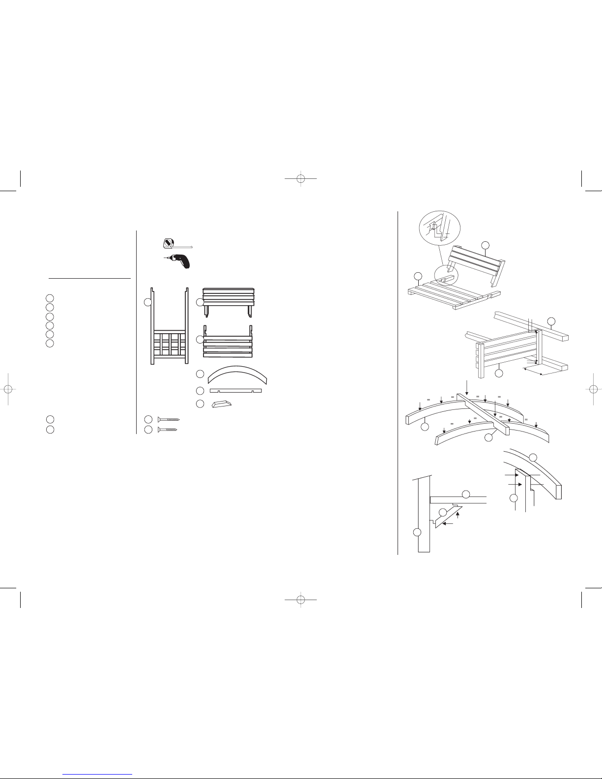
P
ARTS LIST
SIDE SECTIONS x 2
SEAT BACK x 1
SEAT x 1
ROOF BEAMS x 2
ROOF RAFTERS x 5
SUPPORT STRUTS x 2
HARDWARE PACK
SCREWS - 4mm x 6cm csk x18
SCREWS - 2.5mm x 5cm csk x10
A
w
y
w
y
D
E
Fig.1.
Fig.2.
ASSEMBLY
S
TEP 1
Assemble the seat (B+C) using screws
a
s shown in Fig.1
.
STEP 2
L
ay one of the Side Assemblies (A)on a
clean flat area and attach the seat to the
s
ide assembly using screws [
w]
. The seat
should be positioned approximately
45cm from the bottom of the posts as
F
ig.2
.
STEP 3
Turn the assembly onto the Seat Back (B)
so that the second side may be attached
t
o the other end of the seat assembly.
Ensure the seat height is the same on
both sides.
STEP 4
Stand the assembly upright with care.
STEP 5
Take the two Curved Beams (D)and
mark the positions for the Rafter (E).
Start at the centre of the beams and
mark two equally spaced positions either
side of centre as
Fig.3.
STEP 6
Fit the curved roof beams to the top of
the posts ensuring that the overhang at
each end is the same using screws [
w] as
Fig.4.
STEP 7
The Rafters (E) should now be fitted at
the positions marked on the beams using
screws [y].
STEP 8
Finally fix the Struts (F) at the front of the
arbour between the post and underside
of the seat using screws as
Fig.5.
B
C
F
A
B
C
D
E
F
Fig.3.
w
ww
w
w
w
w
y
y
y
y
y
y
y
y
45cm
w
B
C
C
D
D
A
E
A
Fig.4.
Fig.5.
C
F
A
Romana Arbour [A5 4pg instructions] 10/3/17 10:07 Page 2
 Loading...