

Grange LIVORNO ARBOUR Assembly Instructions Manual
D
E
B
G
I
J
J
M
F
L
L
H
A
A
C
CARE OF YOUR ARBOUR
The Livorno Arbour is made of planed pressure treated and FSC certified timber
a
n
d as such is guaranteed against rot for a minimum of 15 years. However, it
s
h
o
ul
d be remembered that as a natural product, timber is subject to movement
and weathering as it seasons. It is not uncommon for small spits to occur when
drying and warping when timber is allowed to dry too rapidly. These will normally
go back when humidity rises, it is nature at work and not considered a fault.
AFTERCARE
I
t
s c
o
l
o
ur will also change with time, A re-treatment, as required with a proprietary wood treatment is recommended.
S
IDE SECTIONS
S
EAT BACK
BOX SEAT (FRONT)
SEAT SUPPORT (BACK)
S
EAT LID BACK BEAM
SEAT LID
ROOF BACK SECTION
R
OOF PANELS
ROOF COVER STRIP
F
ASCIA BOARD
B
OX BASE - SLATS (a)
BOX BASE - SLATS (b)
SIDE SEALER STRIPS
FINIAL
A
D
E
B
C
G
H
I
J
K
L
M
F
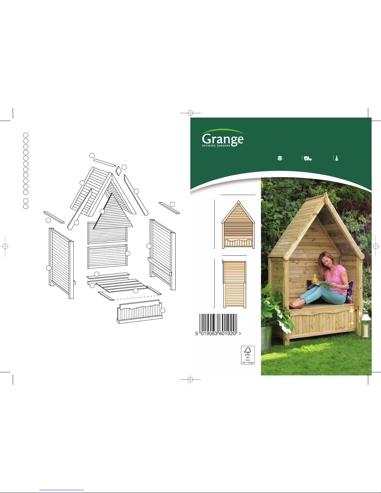
LIVARB - 220cm [H] x 143cm [W] x 64cm [D]
LIVORNO ARBOUR
Self-Assembly required Home Delivery available Pre-Painted available
www.grangefen.co.uk
All products and related emblems featured are
trademarks of Grange Fencing Ltd.
©2015 Grange Fencing Ltd All rights reserved.
In line with the Company’s policy of
continuous product development, the right
is reserved to change and improve product
design without prior notice.
CODE: LIVARB
PLAN
220cm
220cm
143cm
64cm
Livorno Arbour [A5 4pg instructions] 4/2/16 09:40 Page 1
BEFORE YOU START
W
h
e
n you are ready to start make sure
you have the right tools to hand, plenty
of space and a clean dry area for assembly.
Drill pilot holes to aid assembly.
Please check the packs and make sure that
you have all of the parts listed above. If
n
ot, contact your retailer who will be able
to help you.
T
hank you for choosing this garden structure from Grange. In order to gain the most
benefit from it please read the following instructions carefully.
T
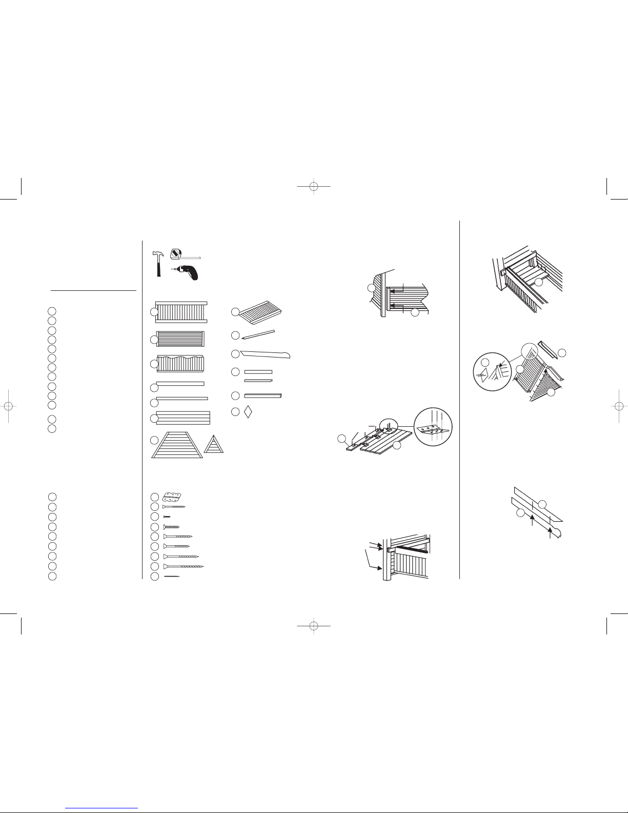
OOLS REQUIRED(Not Supplied)
POWER DRILL/SCREWDRIVER
w
ith posidrive No.2 bit
3
mm DRILL FOR PILOT HOLES
TAPE MEASURE
H
AMMER
P
ARTS LIST
SIDE SECTIONS x 2
SEAT BACK x 2
BOX SEAT (FRONT) x 1
SEAT SUPPORT (BACK) x 1
SEAT LID BACK BEAM x 1
SEAT LID x 1
ROOF BACK SECTIONS x 1
ROOF PANELS x 2
ROOF COVER STRIP x 1
FASCIA BOARD x 2
BOX BASE - SLATS (a) x12
BOX BASE - SLATS (b) x 2
SIDE SEALER STRIPS x 2
FINIAL x 2
HARDWARE PACK
HINGES x 3
SCREWS - 2.5mm x 5cm x 2
SCREWS - 3.5mm x 1.5cm x 9
SCREWS - 3.5mm x 3.5cm x16
S
C
R
EWS - 3.5mm x 7cm x 8
S
CREWS - 4mm x 6cm x14
SCREWS - 4mm x 9cm x 2
SCREWS - 4mm x 12cm x 4
NAILS - 1.5mm x 3.5cm x50
A
p
q
r
s
t
u
v
w
x
s
t
u
v
w
x
p
q
r
D
E
Fig.1.
STEP 3
Fix the second back panel above the one just fitted.
The top of the second panel should be level with the
top of the side section.
STEP 4
Fix the second side panel to the other end of the back panels.
STEP 5
Take the back support (D) and fix to the back panel using
two screws [u] through the back panel. This fits between
the prefitted side section supports.
STEP 6
Fix the hinges [p] to the Seat Lid Back Beam (E) as shown
in Fig.2. using screws [r].
STEP 7
The Seat lid back beam may now be fixed to the back
support using three screws [s].
STEP 8
Now rest the seat lid on the side supports and position it
so that the hinges can be screwed in place. Check that it
can be raised without fouling.
STEP 9
The Box seat front should now be fitted. Use one of the box
f
l
oor slats and the seat lid to determine the position. Fix in
place with screws [u] as shown in Fig.3.
A
SSEMBLY
S
TEP 1
Take one of the Side sections (A) and a Seat Back (B).
S
TEP 2
Screw together using screws [t] as shown in Fig.1. The panel
should be 9cm from the bottom of the post.
S
TEP 10
Fit the Slats (K) evenly into the bottom of the box and nail in
p
lace as Fig.4
.
STEP 11
Take the two roof panels (H)and jo in them together at the
apex using two screws [v] as shown in Fig.5. one either side.
STEP 12
The back panel (G) for the roof is in two part s. Push these
together using the tongue and groove. Place this onto the
ledge inside the assembled roof and push into the apex as far
as possible. Fix in place using nails [
x] as shown in Fig.5.
STEP 13
Position the roof onto the base assembly and centralise it.
Screw in place using screws [
w], one on each corner into the
top of the posts.
STEP 14
Fix the Fascias (J) to the front of the roof assembly using
screws [
s] as shown in Fig.6.
STEP 15
Fix the finial (M) at the apex of
t
h
e r
o
of using screws [
q] a
s s
h
o
wn in
Fig 5.
STEP 16
F
in
a
lly fit the roof cover strip (
I)
using four of the nails provided.
B
C
G
H
I
J
K
L
M
F
t
t
A H
I
J
K
L
M
B
C
D
E
F
G
(a)
(b)
Fig.2.
r
u
Fig.3.
F
ig.4.
Fig.5.
Fig.6.
r
F
A
B
E
q
s
s
v
x
M
G
K
H
I
J
H
Livorno Arbour [A5 4pg instructions] 4/2/16 09:40 Page 2
 Loading...