

Page 1
User's Guide to the OFI-3
Optical Fiber Identifier
English Versio n
OFI-3
Page 2

User's Guide to the OFI-3
Optical Fiber Identifier
Page 3

CONTENTS
PAGE
1 Introduction
2 Warr anty
2.1 One Year Limited Warranty
2.2 Exclusions
2.3 Returning Product
2.4 Contact us
3 Safety Information
4 Preparing for Operation
4.1 Unpacking the instrument
4.2 Battery
5 Operation
5.1 Controls and connectors
5.2 Powering on the instrument
5.3 Traff ic detecting
5.4 Frequency detecting
5.5 Signal intensity
5.6 Self-calibrating
6 Specifications
7 Maintenance
1
2
4
5
7
14
16
Page 4
1
OFI-3 / Introduction
1 Introduction
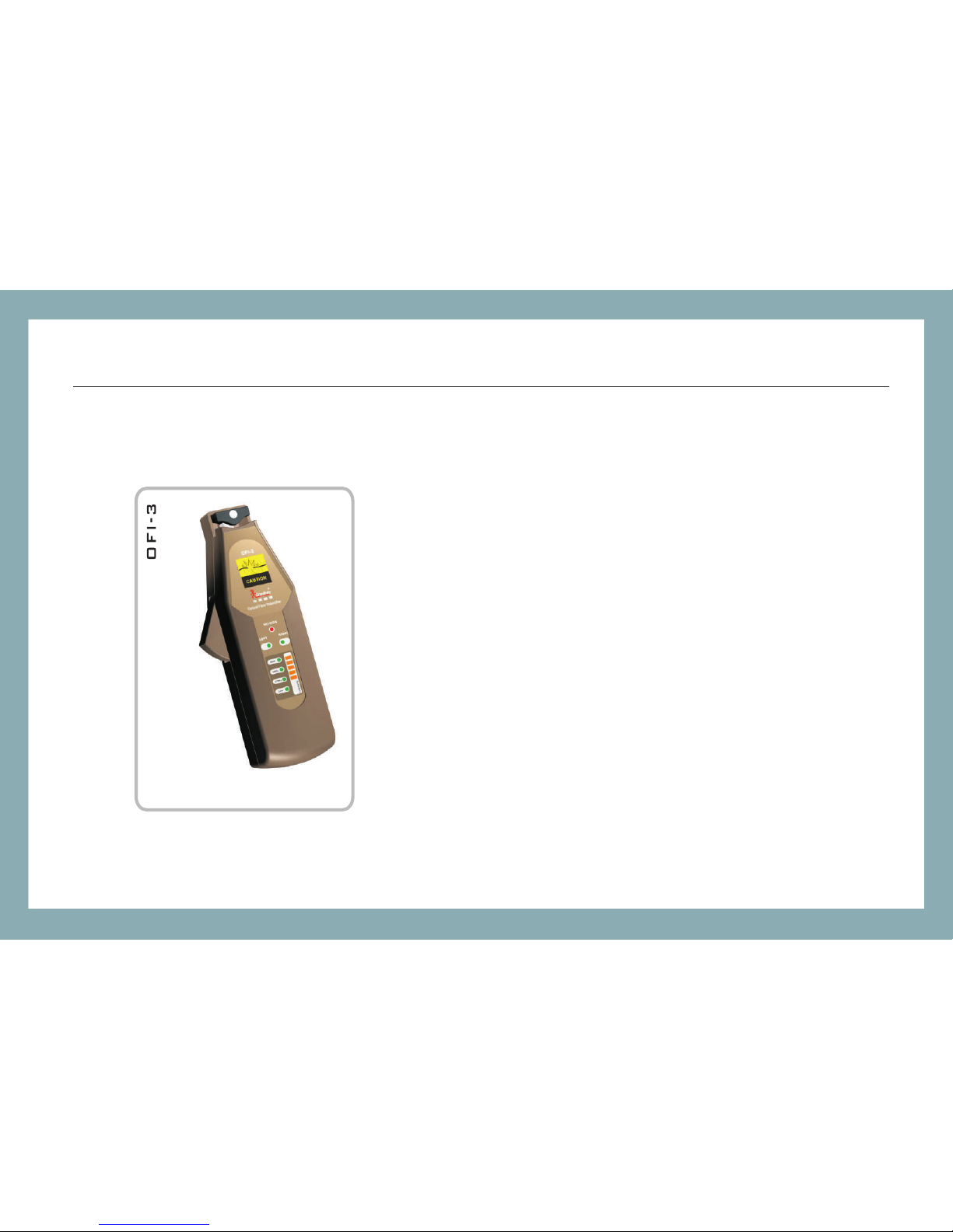
The OFI-3 optical fiber identifier is an inexpensive, portable
instrument designed to identify optical test tones and live
traffi c without disconn ecting live syste m. By simply
clamping the OFI-3 onto a fiber, the instrument will indicate
if there is a signal, or traffi c and show the signal d irection. It
can detect a variety of optical tones, 270Hz, 1KHz and
2KHz.
The OFI-3 is recommended for both 0.25 mm bare fiber,
0.9mm tightly buffered fi ber and 2/3mm jacke t fiber. When
testing jacket fibers, the slim design of the OFI-3 allows
easier access to a splice tray where the amount of
workspace is limited. The c lamping trigger i s designed to fit
the natural motion of the operator ’s hand. The ins trument is
ruggedly constructed and reliable to use.
Page 5

2
OFI-3 / Warranty
2 Warranty
One Year Limited Warranty
Grandway products are warranted against the de fective compone nts and workmansh ip for a period
of one year from the date of delivery to the original customer. Any product f ound to be defectiv e
within the warranty period would be returned to Gr andway authoriz ed service center f or repair,
replacement and calibrati on.
Exclusions
The warranty on your equipmen t shall not apply to de fects resulting f rom the following :
Unauthorized rep air or modification
Misuse, negligen ce, or accident
Returning Product
To return product, you may contact Grandway to obtain additional info rmation if necess ary.
To serve you better, please specify the reasons for the return.
All delivery and mails should b e sent to the followi ng address:
Page 6

3
Grandway Customer Service
6F, Xin'an building No. 99 Tianzho u Road
Shanghai, 200233 P.R. China
Contact Us
Tel: 0086-21-54451260/61/62/63
Fax: 0086-21-54451266
E-mail: [email protected]
Websit e: www.grandway.com.cn
OFI-3 / Warranty
Page 7

4
OFI-3 / Safety Information
3 Safety Information
Never look directly into optical outputs or a fiber while the equipme nt is on.Invisibl e laser beam
may damage your eyes.
Do not short-circuit the terminal of AC adapter / charger and the batteries.Excessive electrical
current may cause personal injury due to fumes,electric shock or eq uipment damage.
Connect AC power cord with the equ ipment and wall soc ket properly. While inserting the AC plug,
make sure there is no dust or dirt on the terminals and both plugs are fully se ated. Incomplet e
engagement may cause fuming, electric shock or equipment damage a nd may result in pers onal
injury.
Do not operate the equipment near hot objects, in ho t environments, i n dusty/ humid atmo sphere
or when condensation is prese nt on the equipment . This may result in electric shock , product
malfunction or poor performance.
Warnings!
Page 8

5
OFI-3 / Preparing for Operation
4 Preparing for Operation
4.1 Unpacking the instrument
Packing material
We sugge st that you keep the or iginal packing ma terial. Using the o riginal packing material is your
guarantee of protecting the instrument during transit.
Checking the package contents
The standard accessories of OFI-3 are as follows:
Main unit User's Guide
Plungers 2*1.5V Alkaline Batteries
Carrying Case Qua lity Check Report
Checking for damage in transit
After unpacking the instrument, check to see whether it was damaged in transit. This i s particularly li kely
if the outer casing is clearly damaged. If there is damage, do not attempt to operate the instrument or to
repair it without authorization. Doing so can ca use further damag e and you may lose your w arranty
qualification.
Page 9

6
4.2 Battery
The OFI-3 instrument is powered by two 1.5V AA batteries. There is a “Low ” battery indicat or on the
panel board. It turns on if there is not enough power to supply the instrument. That is when y ou should
replace the battery with a new one. To replace the bat tery, please remove the battery plate on the back
side of the instrument with a screwdriver.
Note: 1 It is advisable to use 1.5V alkaline batteries. The Low Batte ry Indicator may li ght up if you use
rechargeable batteries.
2 To eliminate the possibility of acid leakage, please take out the batteries if the unit is not used for a
long time.
OFI-3 / Preparing for Operation
Page 10
7
OFI-3 / Operation
5 Operation
5.1 Controls and connectors
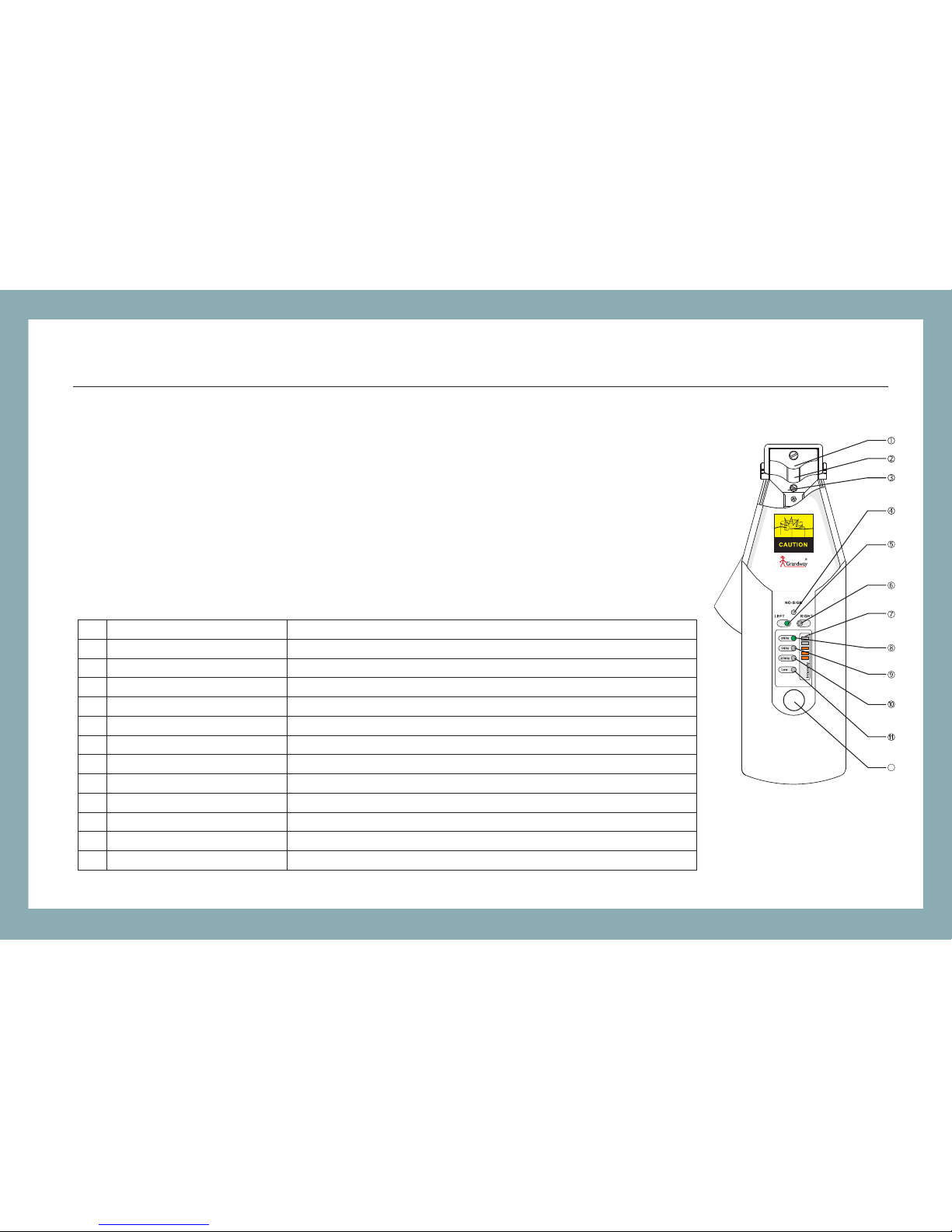
5.1.1 Front (Panel B oard)
Key / Indicator
Plunger
Fiber Groove
PD Headstock
No Signal Indi cato r
Left Traffic Indic ator
Right Traffi c Indi cato r
Signal Inten sity I ndic ator
2kHz Indicat or
1kHz Indicat or
270Hz Indica tor
Low Battery In dica tor
Adjusting Ke y
Note
Three availab le ty pes : H0. 25m m, H0 .9m m, H3.0mm.
A slot to place tes ted fi ber.
Lights up if the re is no t a sign al in tested fiber.
Lights up if the s igna l in tes ted fiber is from rig ht to le ft.
Lights up if the s igna l in tes ted fiber is from lef t to rig ht.
To show the signal i nten sity l evel. The higher, t he str onge r.
Lights up if the w ave fr eque ncy is 2kHz.
Lights up if the w ave fr eque ncy is 1kHz.
Lights up if the w ave fr eque ncy is 270Hz.
Lights up when t here i s not en ough power.
Self-calib rate s.
H2.0mm,
No.
1
2
3
4
5
6
7
8
9
10
11
12
ADJU ST
12
Page 11
8
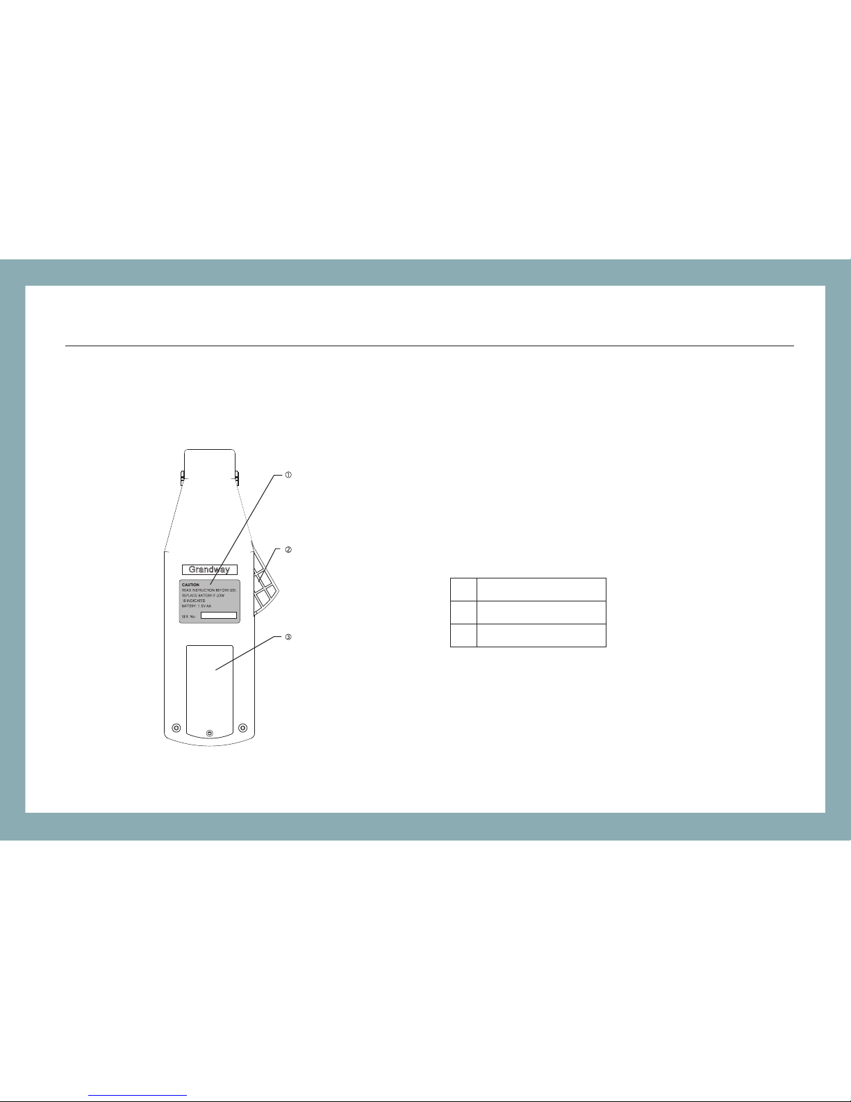
5.1.2 Back & Side
Serial Number
Clamping Trigger
Battery Plate
1
2
3
OFI-3 / Operation
Page 12
9
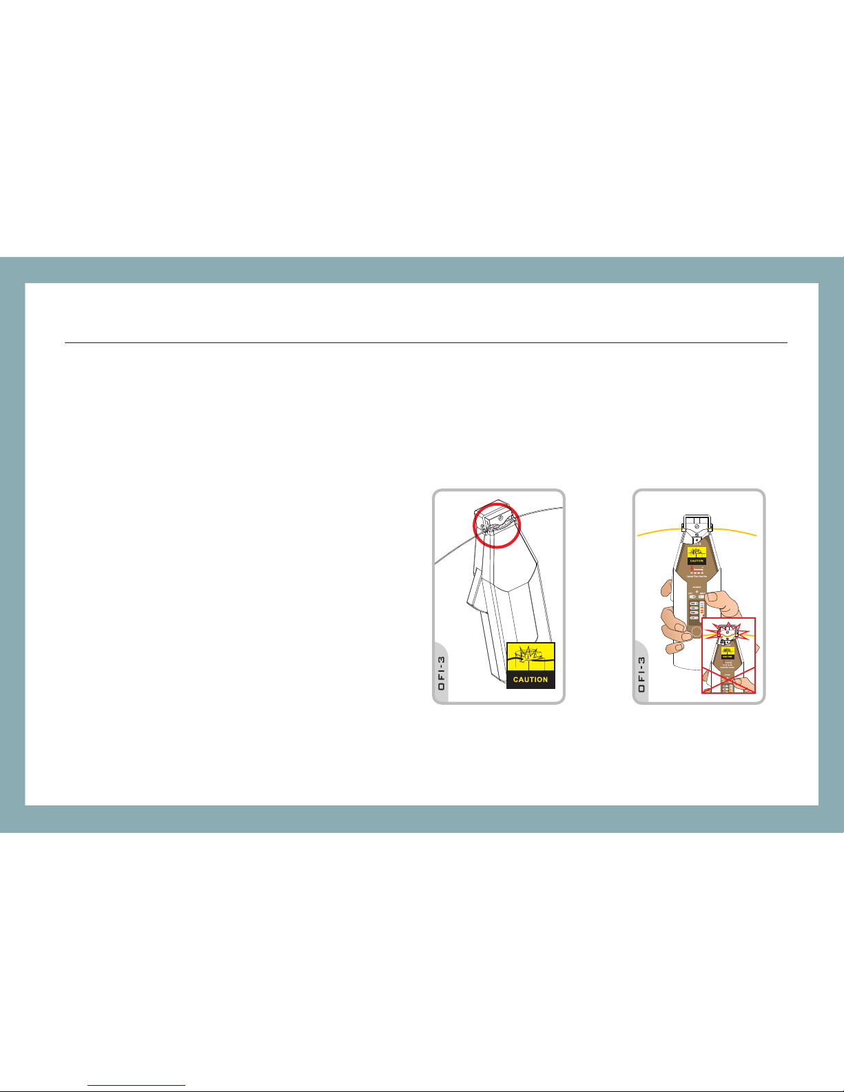
5.2 Powering on the instrument
Gently insert the tested fiber into the
groove at the top of instrument. Pull the
clamping trigger slowly to de press the
fiber against the optical assembly. The
instrument powers on when the detector
plunger has closed and the fibe r is in the
appropriate position.
Note: Please be careful while placing the
fiber in the provided slot. Force the fiber
into the headstock. Misaligning the fiber
may induce optical losses abo ve what the
specification demonstrates.
ADJUST
OFI-3 / Operation
Page 13
10
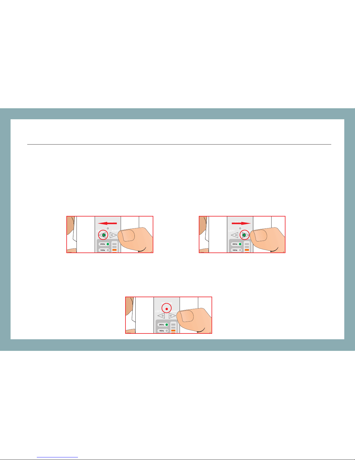
5.3 Traffic detecting
If the tested fiber is carrying signal, a Traffic I ndicator illumi nates to show the dir ection, left or
right.
When no signal is present or the signal to be tested is too weak for the instrument to detect, the
No Signal Indicator illumin ates.
OFI-3 / Operation
Page 14
11
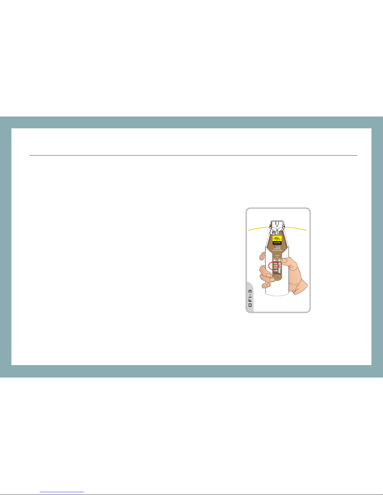
5.4 Frequency detecting
If the tested fiber is carrying 2kHz, 1kHz or
270Hz modulated wave, the respective
modulation indicator illu minates and the
instrument makes a buzzing sound.
Note: Th e instrument may no t recognize the
frequency correctly if the signal is too weak or
the frequency is not stable.
ADJUST
OFI-3 / Operation
Page 15
12
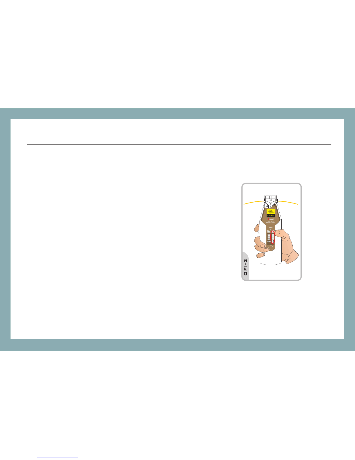
5.5 Signal intensity
The signal intensity indica tor on the panel boar d lights
up to tell you how strong the signal is. There are 5
LEDS aligning in a line. More of them illuminate
meaning the signal is stronge r.
ADJUST
OFI-3 / Operation
Page 16
13
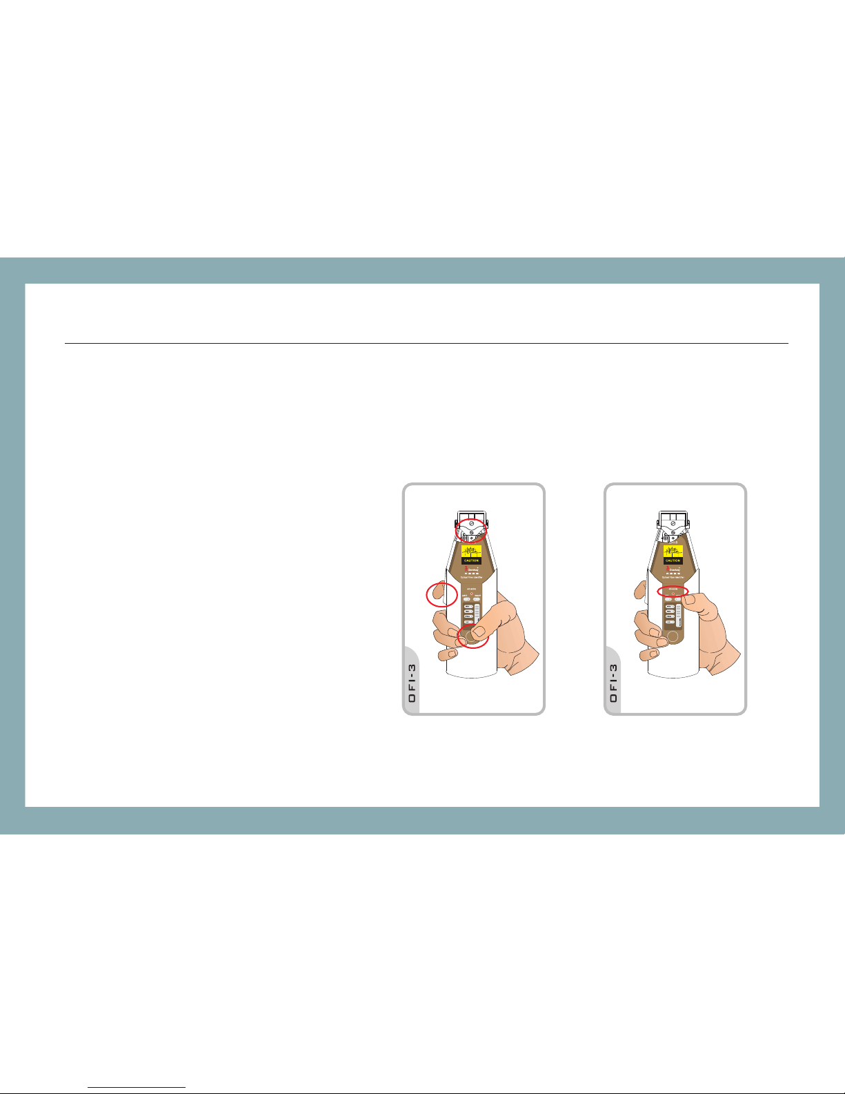
5.6 Self-calibrating
The instrument may need a little
adjustment after long-term disuse or a
sudden change of the environm ent
such as temperature or light variation.
Change the plunger to the H0.25 type,
pull the clamping trigger, the n press
the "Adjust" key shortly to start the
self-calibration which la sts about 1030 seconds. When it finishes, the
instrument makes a buzzing sound
and the "No Signal" Indicator blinks.
ADJUSTADJUST
OFI-3 / Operation
Page 17

-20dBm
-10dBm
-10dBm
-10dBm
-30dBm
-18dBm
-18dBm
-18dBm
Sensitivit y
(Minimum rec ogni zable optical pow er int ensity in the fiber )
Continuous Wav e
2KHz Modulat ed Wave De tection
1KHz Modulat ed Wave De tection
270Hz Modula ted Wave D etection
1310nm(typ ical )
1550nm(typ ical )
14
6 Specifications
Optical Specifications
Model
Recognizab le Wavel engt h Range
Recognizab le Sig nal Type
Detector Typ e
Available P lung er
Detecting Se nsit ivit y
Power
OFI-3
900nm - 1650nm
CW,270Hz±5% ,1KH z±5% ,2KHz±5%
InGaAa 2pcs
H 0.25 for bare fi bers
H 0.9 for tightl y buffere d fibe rs
H3.0 for jacke t fibe rs
≤-50dBm
2*1.5V AA batter ies
OFI-3 / Specification
Page 18

15
General Specifications
Op e r ation Temperature -10℃~+50℃
St o rage Temperature -20℃~+70℃
Si z e(H*W*D) 3.6cm*6.2cm*20.2cm
We i ght 0 .2 7 k g
OFI-3 / Specification
Page 19
OFI-3 / Maintenance
16
7 Maintenance
1. All the specifications of OFI-3 series are tested with cleaned Corning SMF-28TM/SMF-D pure nondispersion coated fiber. The testing perfor mance will be affected whe n using different brands or types
of fibers with various coating color.
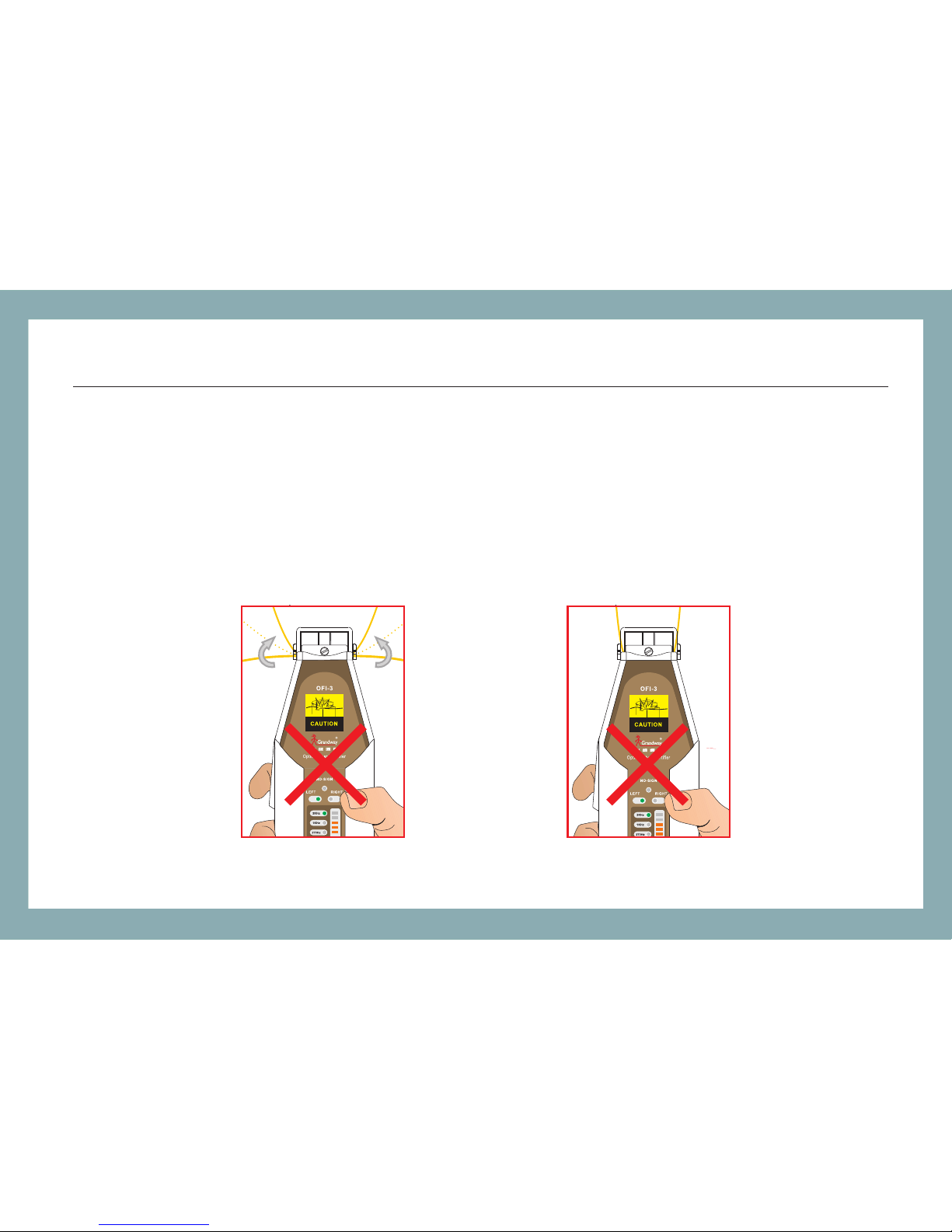
2. Please do not bend the fiber excessively; which m ay lead to misjudgm ent on traffic or even breaking
the fiber.
Page 20
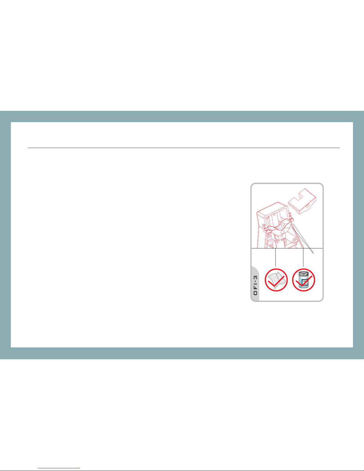
3. Keep the optical receiver clean and use cleanin g oil when
testing bare fiber to achieve the best performance.
4. To clean th e optical assembl y, remove the clamp and gently
clean the prism and optical win dows using cleani ng pads and
cleaning oil. Do not immerse the plunger assembl y in alcohol.
NOTE: Specif ic at io ns , te rm s an d co nd it io ns a re s ub je ct t o ch an ge w it ho ut n ot ic e.
©Copyright 2 00 6 Gr an dw ay. All rights reser ve d.
Grandway and i ts l og o ar e tr ad em ar ks o f Gr an dw ay.
Printed in Chi na .
17
OFI-3 / Maintenance
Removing the c la mp
before clean in g
Cleaning oil
Cleaning pad
 Loading...