

Grandway FHO2000-D26, FHO2000-D35 User Manual
1
MINI OTDR
Manual
Version E0000

2
Foreword
Thank you for purchasing MINI OTDR (Optical Time Domain
Reflectometer).This user’s manual contains useful information about the
instrument’s functions and operating procedures and the handling precautions
of MINI OTDR OTDR.To ensure correct use, please read this manual
thoroughly before beginning operation.After reading the manual, keep it in a
convenient location for quick reference whenever a question arises during
operation.
Note
• The contents of this manual are subject to change without prior notice as a
result of continuing improvements to the instrument’s performance and
functions. The figures given in this manual may differ from those that actually
appear on your screen.
• Every effort has been made in the preparation of this manual to ensure the
accuracy of its contents. However, should you have any questions or find any
errors, please contact your nearest Company dealer.
• Copying or reproducing all or any part of the contents of this manual without
Company’s permission is strictly prohibited.

3
Trademark
• Microsoft, Windows, and Windows XP are either registered trademarks or
trademarks
of Microsoft Corporation in the United States and/or other countries.
• Adobe and Acrobat are trademarks of Adobe Systems Incorporated.
• For purposes of this manual, the TM and ® symbols do not accompany their
respective trademark names or registered trademark names.
• Other company and product names are trademarks or registered trademarks
of their respective holders
Version
Version 1.0 2012

4
Standard Accessary
OTDR standard accessary showed in next table.
Num.
Description
Quantity
1
Power Adapter(220V 50Hz)
1
2
Power Patchcord
1
3
Data Cable
1
4
CD
1
5
Carrying Case
1
6
Securing Strip
1
7
Manual
1
Module
OTDR optional accessary showed in next table.
Num
Module
Description
1
OTDR module
Standard
2
VFL(visual fault locator) module
Optional
3
OPM(optical power meter) module
Optional
※ All changes with standard accessary and optional accessary prices are
subject to change without notice..

5
Safety Precautions
To use the instrument safely and effectively, be sure to observe the
precautions given in the user’s manual. Not complying might
result in injury or death.
Warning
Use the Correct Power Supply
Before connecting the power cord, ensure that the source voltage matches the
rated supply voltage of the AC adapter and that it is within the maximum rated
voltage of the provided power cord.
Use the Correct Power Cord
Use only the power cord that comes with the instrument. Do not use it for other
devices.
Use the Correct AC Adapter
Use only the AC adapter specified for the instrument. Do not use it for other
devices.
Use Only the Designated Battery pack
Use only the battery pack specified for the instrument. Do not use it for other
devices.
Use only this instrument or a charger specified by Company to charge the
battery pack. If the fast charge does not finish after three hours or more, stop
charging the battery pack immediately.
To prevent the possibility of electric shock and accidents, always turn OFF the
power switch and remove the AC adapter power supply from the instrument
when replacing the battery pack.
Do not throw the battery pack into fire or apply heat to it. This can cause
dangerous explosions or spraying of the electrolytes.
Do Not Look at the Laser Light
Do not look at the laser’s direct ray, reflected ray from a mirror, or indirect ray
without the proper protective eyewear. In addition, avoid being exposed to the
laser light. It can cause blindness or damage to the eye.
Do Not Operate in an Explosive Atmosphere
Do not use the thermocouple in a location where any flammable or explosive
gas/vapor is present. Operation in such an environment constitutes a safety
hazard.
Do Not Remove Covers
The covers should be removed by Company’s qualified personnel only.
Opening the cover is dangerous, because some areas inside the instrument

6
have high voltages.
Carrying and Moving the Instrument
Remove all power cords and connection cables from the main unit before
moving the instrument. When carrying the instrument, hold it firmly by the
handle.Also, if storage media is inserted into the instrument, always remove
the storage media before carrying or moving the instrument. Never leave the
media inserted when carrying or moving. The storage media can become
damaged.
Apply Correct Signals to the Optical Connectors
Do not apply light that is —10dBm or greater to the MINI OTDR optical
Connectors.
Doing so may damage the MINI OTDR
7
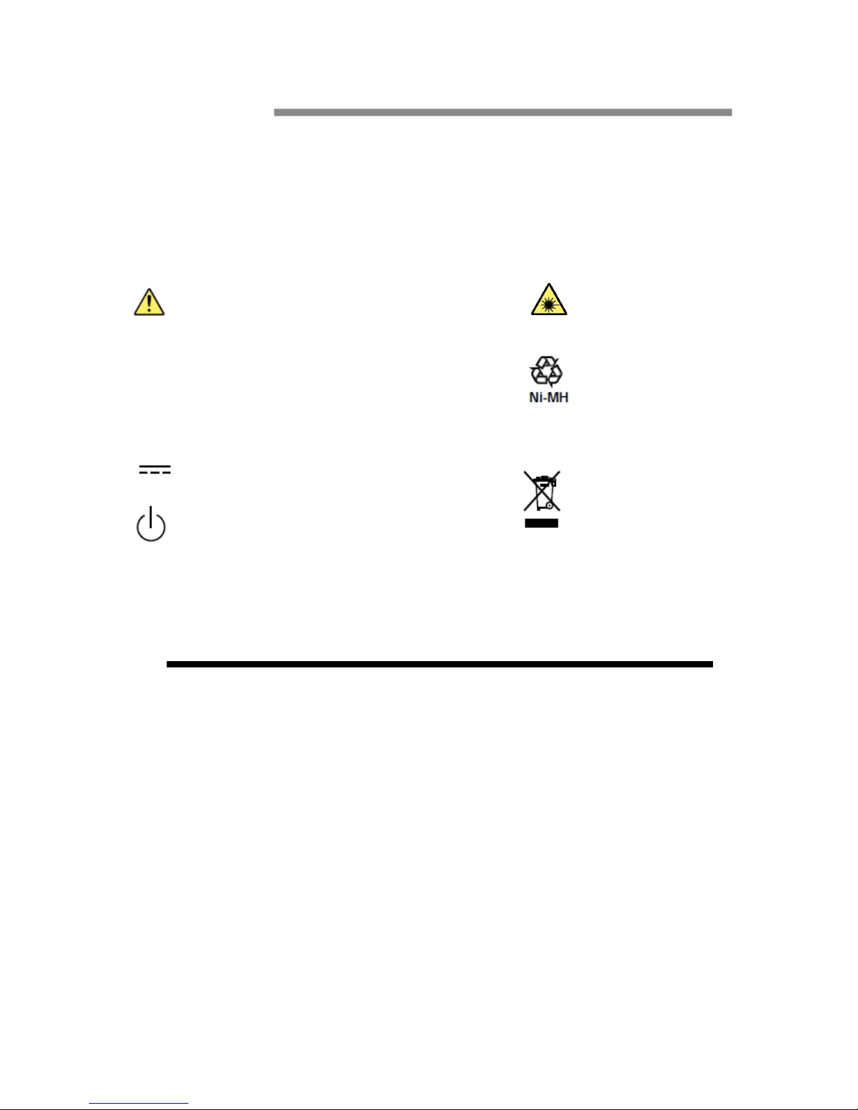
Symbol
Icons on the main body or in manual
Warning: handle with care. Refer to the user’s manual or
service manual.
This symbol appears on dangerous locations on the
instrument which require special instructions for proper
handling or use. The same symbol appears in the
corresponding place in manual to identify those
instructions
Recycle
Stand-by (power)
Direct current
Hazard, radiation of laser apparatus
Comply WEEE(Waste Electrical and
Electronic Equipment ) Directive
(2002/96/EC)

8
Content
0.0Names and Functions of Parts......................................................
0.1 Panel..................................................................................................
0.2 Main Menu Interface................................................................................
0.3OTDR Module Interface............................................................................
0.4 VFL Module Interface...............................................................................
1.0Preparation.....................................................................................
1.1 Turnning on.............................................................................................
1.2 Connecting the Fiber................................................................................
2.0 Introduction of OTDR......................................................................
2.1 Purpose of Measurement................................................................................
2.2 Content of Measurement................................................................................
2.3 Analyze of Curve........................................................................................
2.4 Fundamental of OTDR..................................................................................
2.5 Event Type...............................................................................................
3.0 Setting Measurement Conditions....................................................
3.1Setting to Auto Mode..................................................................................
3.2Setting to Manual Mode.................................................................................
4.0Making Measurements.....................................................................
4.1 Averaging test mode....................................................................................
4.2 Realtime test mode.....................................................................................
4.2.1 Setting wavelength..................................................................................
4.2.2 Setting test range and pulse width..................................................................
4.3 Event List................................................................................................
4.4 Distance Measurement.................................................................................
4.5 OTDR Optimizing Tool................................................................................
4.6 Setting proper parameters..............................................................................
5.0 Expanding the Waveform and Moving the Display Area............
5.1 Switching between Event list and display window.................................................
5.2 Cursor Operation........................................................................................
5.2.1 Activating Cursor.....................................................................................
5.2.2 Moving Cursor.......................................................................................
5.3Curve Operation...........................................................................................
5.3.1Horizontal Zoom.......................................................................................
5.3.2Vertical Zoom........................................................................................

9
5.3.3Horizontal Shift......................................................................................
5.3.4Vertical Shift...........................................................................................
5.4Elaborating Event.........................................................................................
5.5 Switching between curves.............................................................................
5.5.1 Removing Curve(s)..................................................................................
5.6 Removing an event.....................................................................................
5.7Adding an event.........................................................................................
6.0File Operation.................................................................................
6.1Saving Curve...........................................................................................
6.2Loading Curve(s).......................................................................................
6.3Deleting Curve(s).........................................................................................
6.4Copying/Moving Curve(s).............................................................................
6.5File Setting..............................................................................................
6.6Print screen.............................................................................................
7.0Entering Characters.......................................................................
7.1 Renaming...............................................................................................
7.2 Creating Directory.....................................................................................
8.0 VFL(Visual Fault Locator) Module..............................................
9.0OPM(Optical Power Meter Module)(Optional)........................
10.0 Software Update............................................................................
11.0 Background Information on Measurements..............................
11.1 Viewing the Optical Pulse Measurement Waveform............................................
11.2 Terminology...........................................................................................
12.0 Maintenance..................................................................................
12.1Notice...................................................................................................
12.2Cleaning Tools.........................................................................................
12.3Cleaning of Optical Port.............................................................................
12.4Calibration.............................................................................................
13.0 Diagnosis Center...........................................................................
13.1 FAQ ....................................................................................................
13.2 Help information......................................................................................
14.0 Specification...................................................................................
14.1 Physical Parameter...................................................................................

10
14.2 Test Index..............................................................................................
14.3 Dimension.............................................................................................
15.0 Warranty.......................................................................................
15.1 Terms of Warranty....................................................................................
15.2 Exclusions.............................................................................................
15.3 Transportation........................................................................................
15.4 Customer Service and Support.....................................................................
11
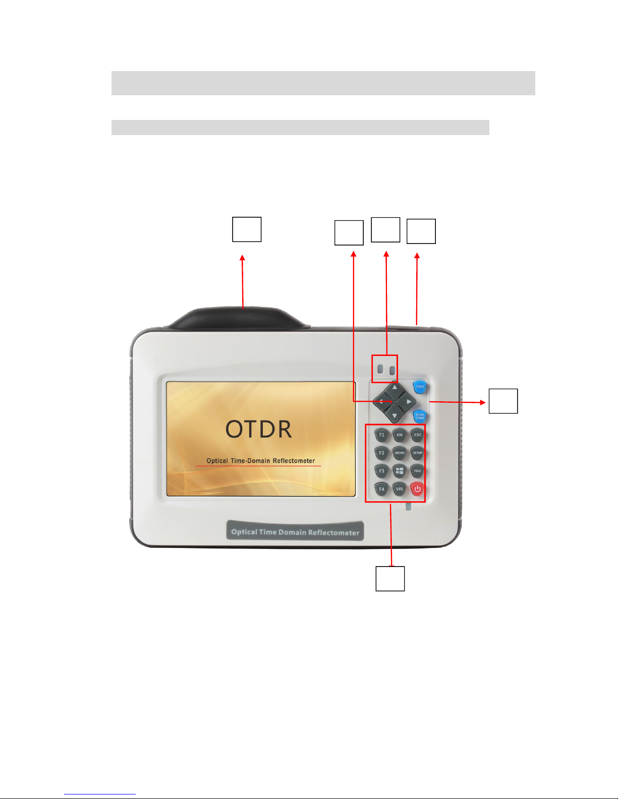
0.0 Names and Functions of Parts
0.1 Panel
I
II
III
VI
V
IV

12
Num
Name
Description
I
Port 1
Including OTDR Test port(FC/UPC)、Visual Fault
locator port(optional)×1、Power Meter port(optional)
×1 , touch pen×1 and USB A type×2
II
Port 2
Including micro-USB×1 and charging port
III
Indicator
Indicate test and power state
IV
Direction
Buttons
Move cursor, menu or files
V
Test button
Averaging Test(TEST) and Realtime Test(REALTIME)
button
VI
Button area
F1~F4: Select relative tag menu
OK: Confirm setting or enter menu
ESC: Cancel setting or enter menu
MENU: Back to main menu
SETUP:Set test parameters
FILE: File manager
VFL:visual fault locator menu
: Printscreen
:Power switch

13
0.2 Main Menu Interface
Num
Function
Description
I
Side menu
Enter relevant interface
II
Function Modules Area
Enter relevant module
III
Basic State Information Area
Display information of date ,time
and power
II
I
III
14
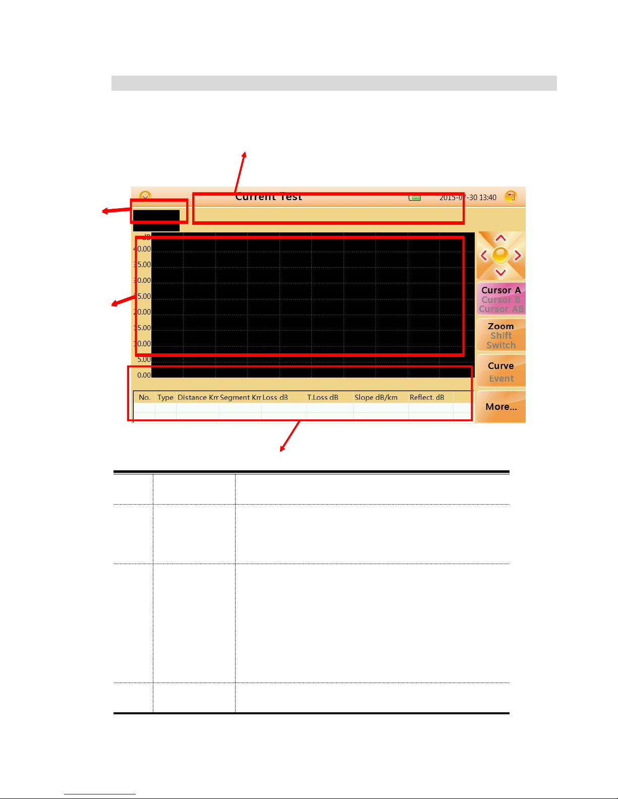
0.3 OTDR Module Interface
Num
Function
Description
I
Thumbnail of
current curve
For user's reference to the integrated curve
II
Curve
display and
operating
area
Display events and curves
III
Event list
Display event information
III
I
II
IV
I
II

15
area
including:"Type","distance(Km)","Loss(dB)","T.Los
s(dB)","Slope(dB/km)" and "Reflection(dB)"
IV
Test
condition
information
area
Display condition information of test
including"PW"(Pulse width),
"WL"(wavelength),resolution of X axis and Y
axis(dB/div),distance,averaging and total loss
from cursor A to cursor B.
16
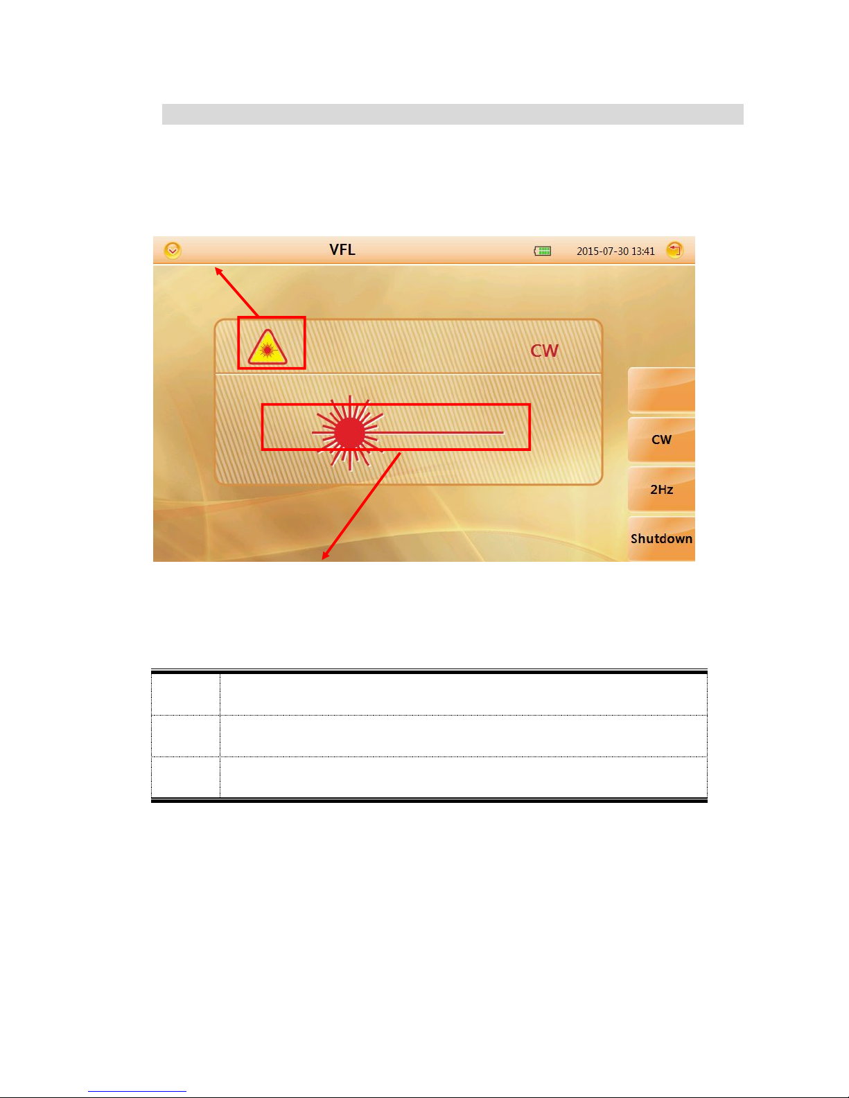
0.4 VFL Module Interface
Num.
Function
I
VFL mode indicator
II
Launching state indicator
II
I
17
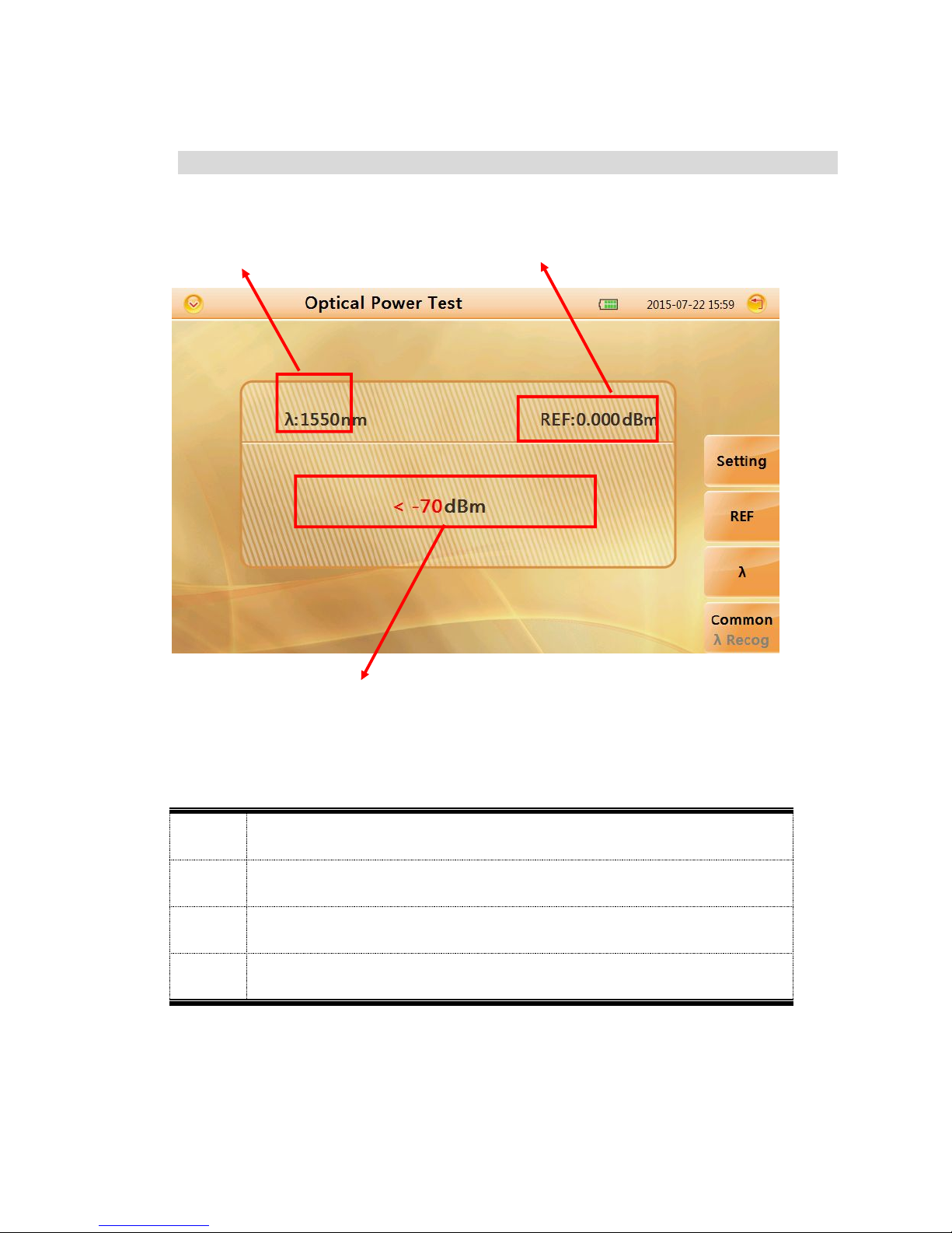
0.5 OPM Module Interface
Num.
Function
I
Power value display
II
Wavelength channel
III
Reference value
I
II
III
18
1.0 Preparation
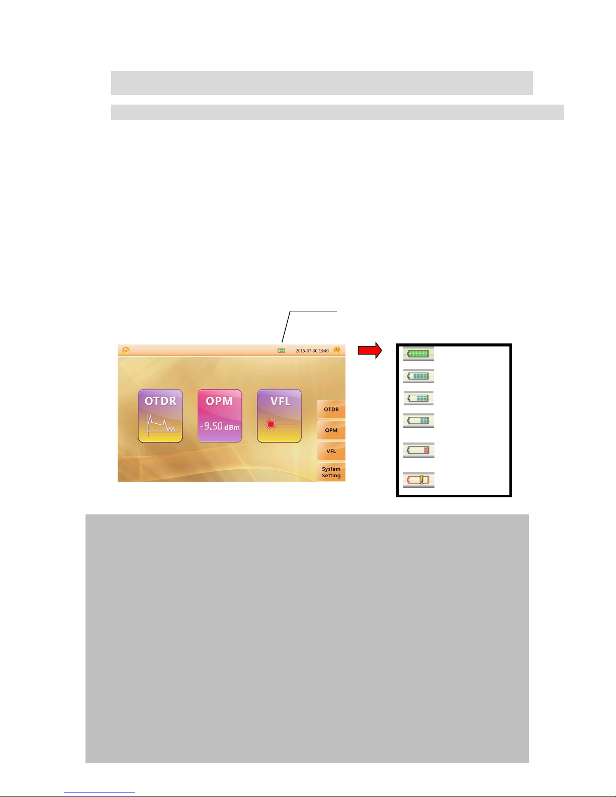
1.1 Turnning on
Press power button(>2s) to turn on OTDR, power state indicator turns
green .when power is low some warning information will display on the screen.
V
Full
80% Power
60% Power
40% Power
20% Power
Less than 20%
Launching state indicator
Green light:Proceed realtime test
Red light:Proceed averaging test
Power state indicator
Green light:Working state or fully charged
Red light:Charging state
Power Indicator
Caution
In case of low power, special icon will appear, and after that for a while MINI
OTDR will turn off automatically.
If it has not been used for an extended period of time,MINI OTDR will turn of
immediately after turned on to protect the internal battery ,please connect the AC
adapter adapter.
Proper charging temperature is: -10~50℃,high charging temperature may shorten
battery life.
Charging time is about 5 hours with power on, about 3 hours with power off.
Don't charge battery more than 8 hours.
19
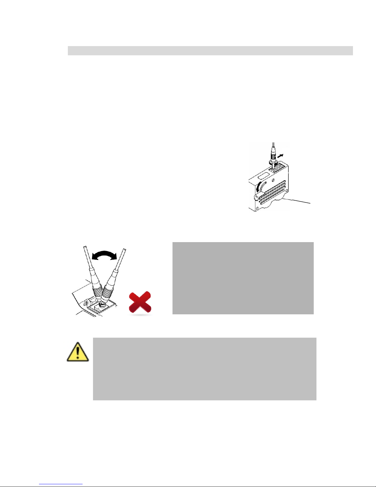
1.2 Connecting the Fiber
Before connect fiber to MINI OTDR,clean fiber end first ,the dust which on
the end of connector may damage the optical port or reduce test quality.
Procedure:
1. Put connector against the cleaner.
2. press the handle of cleaner.
3. Rub each other carefully to clean the contaminant.
4. Repeat procedure 1 and 3.
5. Open the protecting cover of optical port.
6. Insect connector into optical port carefully.
Caution
Insect connector carefully into optical
port,unproper operation may cause the
damage of optical port.
Cleaner
Warning
Before connection make sure that there is no optical signal exist
inside the fiber,any signal which is larger than -30dBm will disturb the
sampling of OTDR,even cause permanent damage of sensor.

20
2.0 Introduction of OTDR
2.1 Purpose of Measurement
OTDR shows the back-scatter light power of the optical signal relative to the
distance. With this information, the OTDR could measure a series of important
information of an optical fiber such as the quality of the line, distance of the line
and etc.
2.2 Content of Measurement
Event position----- a broken point or the end of the tested fiber
Optical attenuation coefficient of a optical fiber
Single event loss, such as the loss of a connection or a macro bending. Or
the loss of a end-to-end line on the tested optical fiber
2.3 Analyze of Curve
OTDR can auto analyze a tested trace, the position process shows below:
Get the reflection events generated by connectors or mechanical splicer.
Non-reflection events(usually it is splicing points or macro bending).
End: the first point which the loss of it is over the threshold would be
scanned as the end of a trace.
Events list: event type, loss, reflection and distance.
Normal Curve
21
A normal trace shows as above, the A mark is a start-peak and the B
mark is a end-reflection-peak. The tested trace is oblique, the total loss
will become bigger with the increasing of the fiber length. The total
loss(dB) divides total length is the average loss(dB/km) of a fiber.
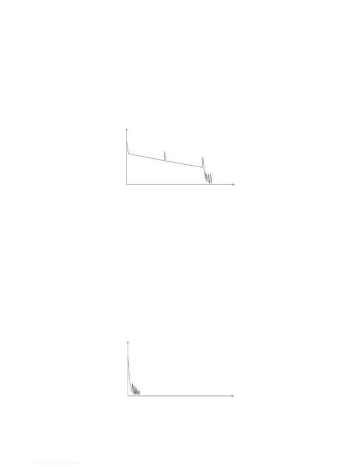
Curve with Jumper Connected
If there is additional reflection peak in a tested trace, this may be
caused by a connection point or some other reasons. Anyway,
appearance of the reflection peak shows that the two connecting
surfaces of the connection are smooth. The smoother the connection
surfaces are, the higher the reflection peak is.
For an instance, if a broken optical line is under test, the OTDR
trace will show a broken point. After a maintenance of this line, use the
OTDR test it again, we may see a reflection peak replacing the broken
point on the OTDR trace, this shows the maintenance is done.
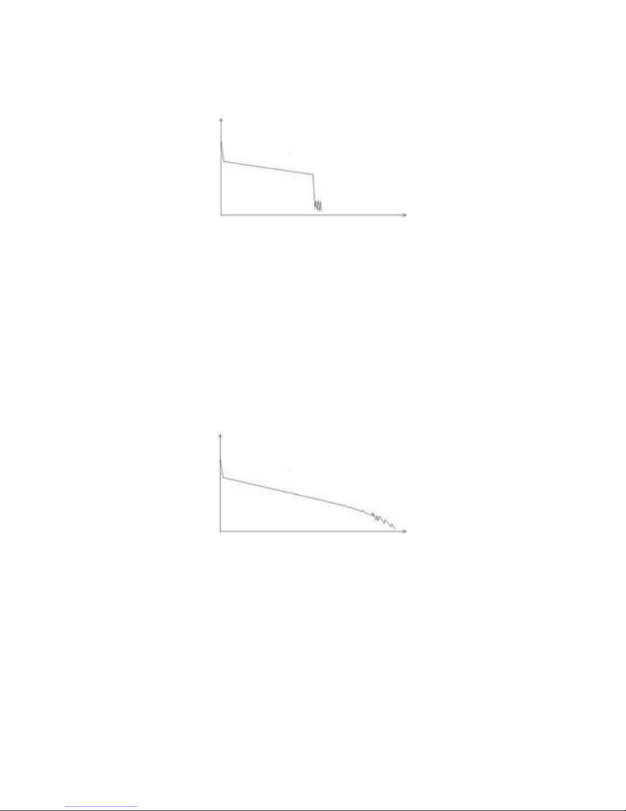
Curve with Broken Point

22
If the tested trace is just like the figure shows above, this might be
caused by several reasons like: a bad connection between the connector
and the lunching port, the optical pulse cannot be launched into the optical
fiber or a short distance broken point of the tested fiber from the initial
connection and the preset testing distance and pulse width is larger.
To fix this problem, we should:
1. Check the connection of the connector and the launching point
2. Reset the test parameters, decrease the preset distance and the
pulse width.
If the problem still exists, we could estimate:
1. The connector of the test fiber is broken or polluted.
2. The launching port on the OTDR is broken or polluted.
3. The distance of the broken point of the from the initial connection is
too close.
Curve with Non-reflective Event
There is a common phenomenon that an obvious step is on the middle of a
tested trace, it often caused by a fiber bending, fiber knot, being pressed by
something heavy or a fuse splicing point. The step means a bigger loss of a
fiber, it is also called event point. If the direction of it is downward, it could be
called non-reflection event. If the direction is upward, we can call it reflection
event.
Sometimes, the loss value could be a negative value, it does not means the
loss does not exist. It is common phenomenon called pseudo gain, it is by a
connection of two fibers with different back scatter coefficient, the scatter
coefficient of the back fiber is large than the front one's. In addition, the
different refract ratio also can cause the phenomenon. To avoid it, we could
test a fiber bi-directionally.
23
Abnormal Condition
The situation that there is no reflection peak at the end of a trace shows
above should be paid attention on. If the distance of the tested fiber is
available and the distance shown on OTDR is not equal to the original distance,
this shows that the fiber might be broken down or twisted and the bending
radius of it is over limited. The distance shown on OTDR is the position of the
fault point.
This phenomenon is often used in maintenance. If a fiber is uncertain, we
can bend a fiber and make sure the bending radius is over limited, then use
real time testing function of the OTDR to confirm the fiber.
Distance is Too long
This situation often happened in a long distance testing, caused by
under-range dynamic range of the OTDR that the energy of it can not support
a long distance transmission or caused by a under-range preset testing range
of distance or pulse width corresponding to the actual fiber length.
To avoid this situation, adjust the testing distance and the pulse bigger and
extend the sampling time.
 Loading...