

Page 1
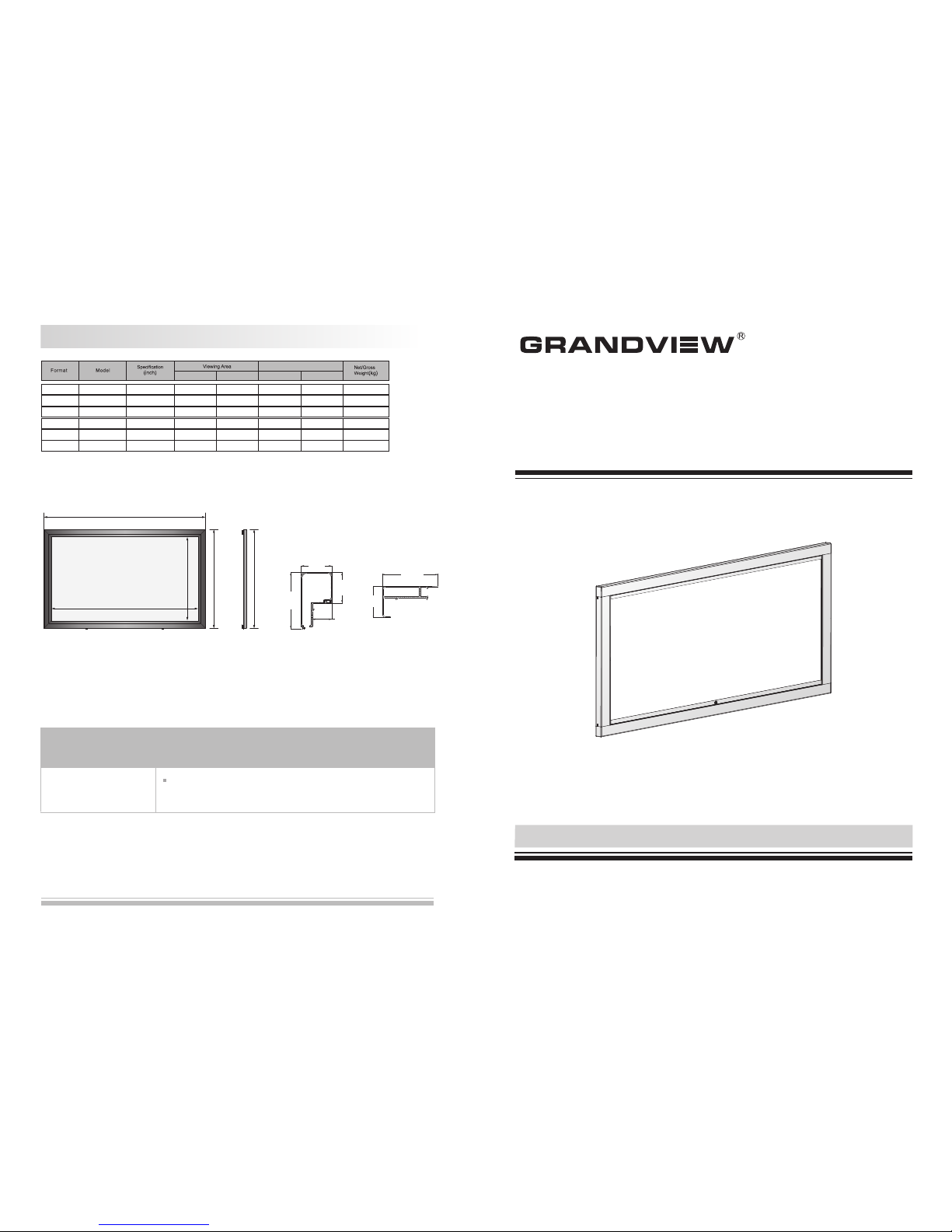
Instruction Manual for
Large-Flat Series Adjustable Fixed-Frame Screen
Model: VMF-xx xLF-
7
Pro du ct Specific ation
Scre en Size
W (mm ) L (mm ) H (mm ) A (mm )
16:9 77 "
80 "
92 "
100"
106”
L
A
W
H
A
Wri nkle on t he fram e
Whe n using n ormal ly, the wr inkle c an be rem oved na tural ly. The rem oving
per iod wil l chang e with 1- 15day s accor ding to t he temp eratu re. Wate ring
can r emove t he wrin kle fas ter.
Thr ee year s warra nty
Gra ndvie w provi des thr ee year s warra nty. Con tents o f warra nty inc lude re place ment of s pare pa rts whi le prob lems
occ ur with c orrec t opera tion. N ot incl ude ina pprop riate ly oper ating t he scre en or uni nstal l the scr een by yo ursel f.
You sho uld res erve in a dvanc e for the r epair w ith Gra ndvie w or appo inted s ervic e cente r.
Sid e Frame B ar
Sid e View
10 5m m
60 mm
Con cave Fr ame
Bar S ide View
11 0m m
38 .5 mm
60 mm
60 mm
LF- -77
LF- -80
LF- -92
LF- -10 0
LF- -10 6
LF- -12 0
VMF
VMF
VMF
VMF
VMF
VMF
120”
170 5
177 1
203 7
221 4
234 6
265 6
958
996
114 5
124 5
132 0
149 4
191 5
198 1
224 7
242 4
255 6
286 6
125 8
129 6
144 5
154 5
162 0
179 4
Thank you for purchasing a Grandview projection screen.
Before use, please read instructions carefully. After installation, store instructions for future reference.
Fro nt View
Sid e View
Note:
1. Due to product updates, sizes and specifications are subject to change at any time. The tolerance for L is approximately ± 5mm (3/16 inches).
2. Actual dimension is measured by: total screen length x end cap depth x end cap height.
Que stion s & Ans wers
Fab rics of G randv iew scr een can b e used fo r years , most pr oblem s are cau sed by si mple in ciden ts. If pr oblem
occ urs, pl ease fi nd the li st belo w for som e commo n solut ions. I f probl ems kee p on, ple ase con tact au thori zed
age nt of Gra ndvie w or call s ervic e numbe r at: (86 20)34 80616 6
REPRODUCING GENUINE COLORS
Page 2
1
Caution
Cle aning
Cle an the ca sing of s creen w ith a sof t cloth a nd luke warm wa ter.
Do no t use any d eterg ent or cl eanin g produ cts.
Ple ase fol low the i nstru ction t o opera te.
Ple ase con tact th e profe ssion al peop le for re pairi ng.
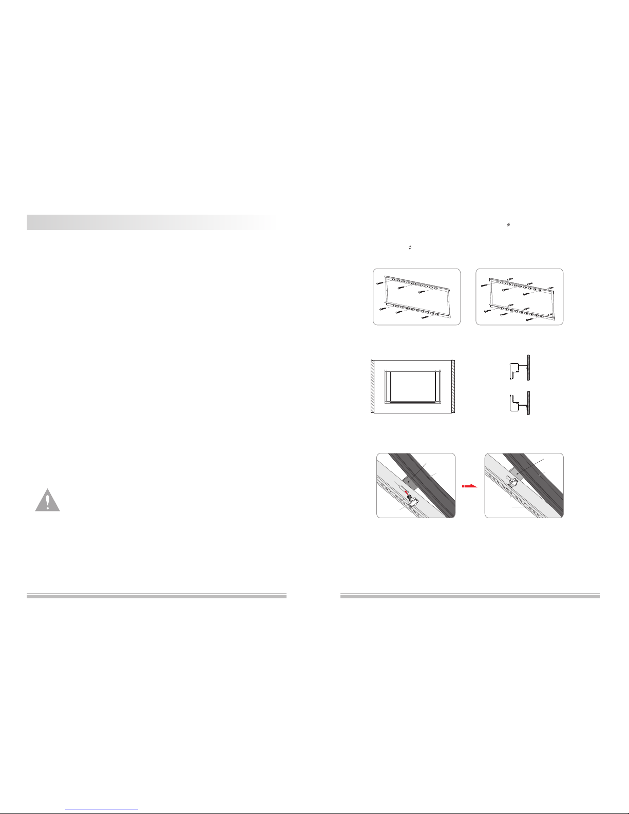
4.Af ter han ging on t he brac ket, pl ease ad just th e scree n horiz ontal ly and en sure th e hole of h angin g piece a nd the
hol es of low b racke t is at the s ame lev el, and t hen fas ten the s ecuri ty fixi ng scre ws into t he hole s (figu re 15-1 6)
fig ure 15 fig ure 16
Top Bracket
Security Fixing Screw
Frame
Hanging Piece
Low Bracket
Security Fixing Screw
Frame
Hanging Piece
G
r
oov
e
fig ure 13 fig ure 14
3.Bu ckle th e hange r of conc ave fra me bar on t op and lo w brack et, fig ure 13- 14.
fig ure 11 fig ure 12
6
ple ase pre vent sc reen fr om wet pl ace to av oid ele ctric o r fire da nger
1. Pl ease re ad care fully w ith thi s instr uctio ns befo re inst allat ion to av oid the d amage c aused b y inapp ropri ate
ins talla tion or o perat ion
2. Pl ease ke ep the sc reen aw ay from h ot sour ces, su ch as rad iator, h eatin g machi ne, fir eplac e, loud speak er
or ot her rel ative d evice .
3. Pl ease ha ndle th e repai r work to t he prof essio nal age nt
4. Pl ease pr event s creen f rom wat er as wel l as putt ing stu ff with w ater (s uch as va se) on th e scree n.
5. Pl ease ma ke sure w hich on e is fron t or back o f produ ct.
6. Pl ease pu t down th e scree n caref ully be cause o f the alu minum a lloy fr ame.
7. Pl ease co ver the s creen b y cloth i f it is not b eing us ed for a lo ng time .
8. Pl ease do n ot poke s creen f abric w ith han d or edge t ools to a void ma rking o n the scr een sur face.
Warn ings:
Ple ase fol low the i nstal latio n as belo w:
a.Wo od wall i nstal latio n: fix th e top and l ow brac ket on th e wall us ing the 5 X60mm w ood scr ew (3 scr ews on
eac h brack et) (fi gure 11) .
b.Co ncret e wall in stall ation : drill s ix prop er hole s on the co ncret e wall wi th elec tric dr ill, th en fix th e top and l ow
bra cket on t he wall u sing th e 5X40m m tappi ng scre w and the n faste n with th e ancho r (3 scre ws on eac h brack et)
(fi gure 12 ).
Page 3
5
Screen I ns ta llation
fig ure 8
3
25
15
10
120
32 23
20
6
6
Lt
12
40
R
8
5
35
40
120
32 23
20
6
6
Lt
12
R
8
5
5
2
15
40
21
3
Front View
Front ViewSide View
Side View
Top Bracket
Low Bracket
unit:mm
Spe cific atio n
Form at
16: 9
77"
80"
Lt (m m)
1000 1000
92" 100 " 106 "
112" 120"
1150 1150
1300 1300
1450
150 "
1750
Table 2: the length of bracket (Lt)
Not e: due to p roduc t updat es, siz es and sp ecifi catio ns are su bject t o chang e at any ti me.
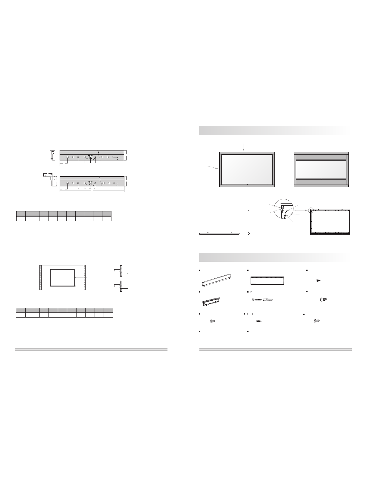
2.Top br acket a nd low br acket a re conn ected b y a belt wh en deli very. The t op brac ket sha ll keep b alanc e with th e
low b racke t verti cally b ecaus e of the un ivers al grav itati on. Ple ase ens ure the d istan ce betw een the t op brac ket
and t he low br acket i s the sam e as the da ta of tab le show s us (if no t, plea se meas ure), a nd then f ix the fr ames on
the w all ( ple ase ref er the da ta to mak e sure th e dista nce bet ween to p and low b racke t) (fig ure 9-1 0)
Top Bra cket
Low B racke t
fig ure 9 fig ure 10
Lin k
Sid e Frame B ar
Con cave Fr ame Bar
幕布
Fro nt View(16 :9)
Top View
Bac k View
Scr een
Rod
Con necti ng Boar d 2
Con necti ng Boar d 1
Spr ing
Scr een
Fro nt View(2. 35:1)
Descrip tion
Accesso ries
2
Co ncav e Fra me Ba r (2pcs)
Si de Fra me Ba r (2pc s)
In stru ctio n Manu al (1 pc)
War rant y Car d (1p c)
5×40m mTapp ing w ith An chor(8 sets)
Top& Low B rack et (1 pc)
Sid e View
M4X 6mm Scr ew(8p cs)
Sec urity F ixing S crew (2 pcs)
M2. 5X8mm Tapp ing Scr ew(4pcs)
7x 0 .8x2 8mm Spri ng(A num ber)
M5X 8mmSc rew 12 pcs( )
148 9
Table 3: the safety distance between two brackets
Spe cific atio n
Form at
16: 9
77" 80"
92"
100 "
106 "
112" 120 "
Note: due t o product upda tes, sizes and s pecificati ons are subjec t to change at any t ime.
1063
1101 1250
1350
1424
1499 1599
150 "
1972
Distance(mm)
1.Ea ch scre en has a se t of brac ket. Ea ch brac ket has a n umber o f corre spond ing hol es and 3 ho les per g roup,
Ple ase ref er to fig ure 8.
Page 4
3
Install ation
Frame In st al lation
Ope n the pac king bo x, chec k wheth er the co mpone nts whi ch need t o be inst alled a re comp lete or n ot acco rding t o
the Ac cesso ry Diag ramma tic Ske tch in th e user ma nual, t hen tak e out all t he smal l compo nents c arefu lly fro m the
pac king bo x and put t hem at a su itabl e place , final ly inst all it ac cordi ng to the o perat ing met hod as be low:
fig ure 1
fig ure 2
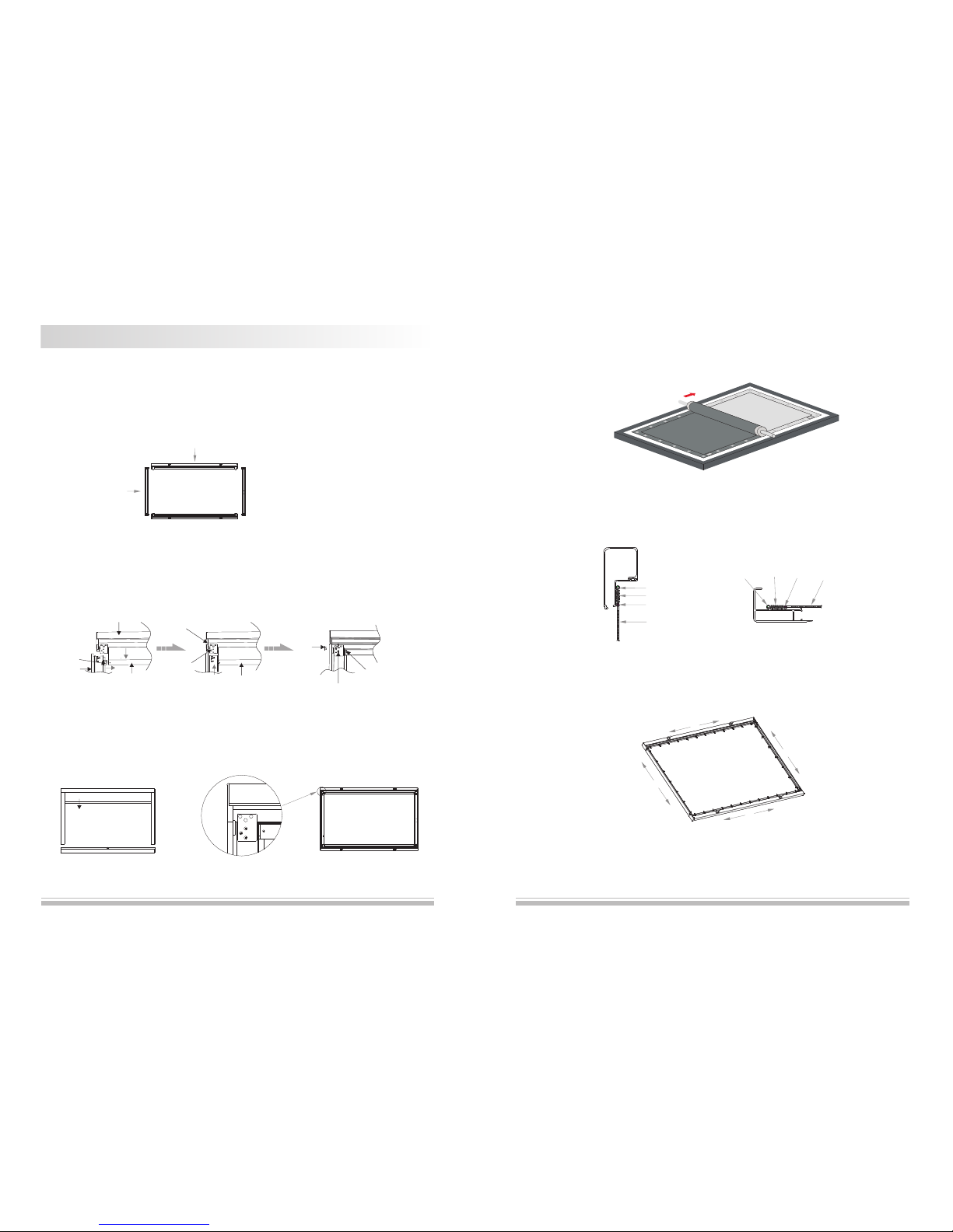
1.Pu t the fix ing lug i nto the s lots of t op and bo ttom ba rs, tak ing the f ollow ing tab le as ref erenc e (figu re 1).
Sid e Frame B ar
Con cave Fr ame Bar
1.Pu ll up the t op bar to a s uitab le dist ance in o rder to a ttach t he bar pl ug into i t. And the n inser t the con necti ng
boa rd 1 and th e conne cting b oard 2 in to Side F rame Ba r (plea se oper ate tog ether i n two sid es). Fi nally, f asten
the c orres pondi ng scre ws: fig ure 2
Top B ar
Plu g
Con necti ng
Boa rd 2
Con necti ng Boar d 1
M4X 6mm
Scr ew
M5x 8mmSc rew
M2. 5x8mm
Tappi ng Scre w
4
fig ure 3
3.Th e insta llati on of low b ar is the s ame as to p bar. Not ice: pl ease pu ll up the t op bar to a s uitab le dist ance an d keep
it w hen op erat ing t his st ep, ot herw ise, the lo w bar c an not be pul led o ut, an d then the in stal lati on is c ompl eted
(fi gure 3) .
fig ure 5
fig ure 6
fig ure 4
Screen F ab ri c Instal la ti on
1.P ut the wh ole fra me upsi de down a nd then u nwrap t he scre en fabr ic (avo id scra ping th e fabri c when
unw rappi ng) (fi gure 4) .
2.Pu t the ten sion ba rs to the f our slo ts of scr een fab ric (no te: thi s is a step s ugges ted to be c omple ted by tw o
per sons, o ne to hol d the scr een fab ric and t he othe r pull th rough t he tens ion bar ) (figu re 5-7) .
Ins talla tion fo r sprin g of conc ave fra me bar
Spr ing
Scr een Fab ric
Rod
Pos ition f or Fram e Hange r
Ins talla tion fo r sprin g of side f rame ba r
Pos ition f or
Fra me Hang er
Spr ing
Rod
Scr een Fab ric
fig ure7
Con cave Fr ame Bar
Sid e Frame
Bar
Top B ar
Pull u p the top b ar
 Loading...