

Page 1
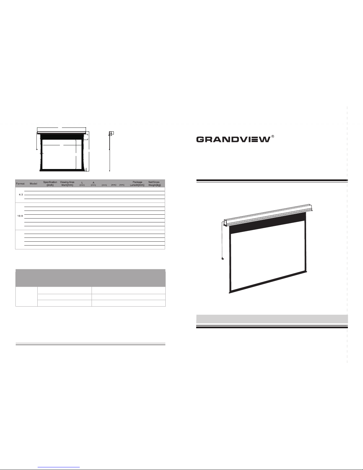
Instruction Manual for
Cyber Series Recessed-Ceiling Screen
Mode l:CB-MIRC or LF-MIR C
Http ://ww w.gra ndvie wscre en.co m
Note:
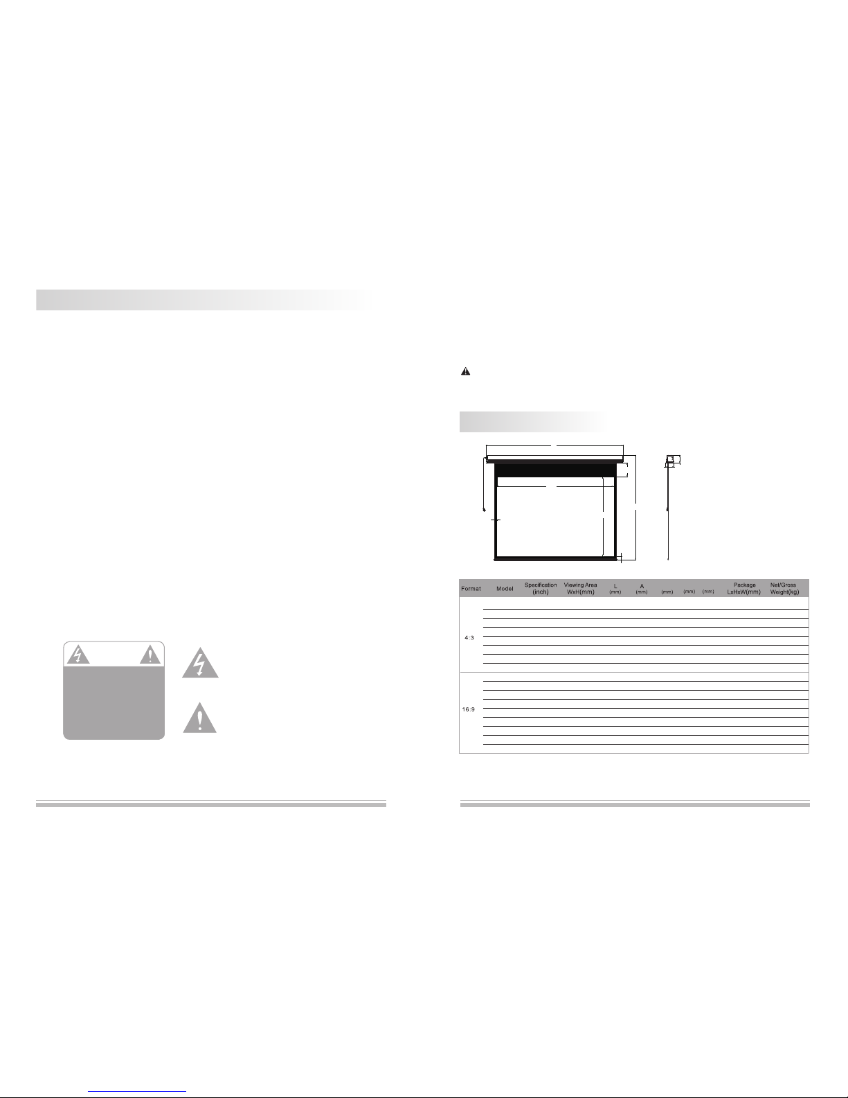
1. Due to product updates, sizes and specifications are subject to change at any time.
The tolerance for L is approximately ± 5mm (3/16 inches).
2. Actual dimension is measured by: total screen length L x end cap depth x end cap height.
B1
B2
H
W
A
B3
L
170
161
GRANDVIEW REPRODUCING GENUINE COLORS
Thank you for purchasing a Grandview projection screen.
Before use, please read instructions carefully. After installation, store instructions for future reference.
LF-M IRC84
LF-M IRC10 0
LF-M IRC12 0
LF-M IRC15 0
LF-M IRC77
LF-M IRC80
LF-M IRC92
LF-M IRC10 0
LF-M IRC10 6
LF-M IRC12 0
LF-M IRC15 0
LF-M IRC10 0
LF-M IRC11 0
LF-M IRC12 0
LF-M IRC13 0
LF-M IRC14 0
84
100
120
150
77
80
92
100
106
120
150
100
110
120
130
140
B1 B2 B3
2.3 5:1
26.8 /30.0
29.4 /33.4
33.0 /37.4
42.2 /47.4
26.4 /29.8
27.0 /30.4
29.0 /33.0
30.5 /34.5
31.6 /35.8
34.2 /38.8
44.0 /49.4
31.2 /35.4
33.0 /37.5
35.0 /39.8
40.5 /45.6
42.8 /48.0
1707 x1280
2032 x1524
2438 x1829
3048 x2286
1705 x 959
1771 x 996
2037 x1146
2214 x1245
2347 x1320
2657 x1494
3321 x1868
2337 x 995
2571 x1094
2805 x1193
3038 x1293
3272 x1392
2321
2646
3052
3667
2319
2385
2651
2828
2961
3271
3940
2951
3185
3419
3657
3891
2196
2195
2480
2937
2195
2197
2197
2196
2196
2195
2519
2196
2195
2194
2194
2193
100
100
100
100
100
100
100
100
100
100
100
100
100
100
100
100
55
55
55
55
55
55
55
55
55
55
55
50
50
50
50
50
665
420
400
400
985
950
800
700
625
450
400
955
855
755
655
555
2431 x260x 226
2756 x260x 226
3162 x260x 226
3777 x260x 226
2429 x260x 226
2495 x260x 226
2761 x260x 226
2938 x260x 226
3071 x260x 226
3381 x260x 226
4050 x260x 226
3061 x260x 226
3295 x260x 226
3529 x260x 226
3767 x260x 226
4001 x260x 226
Quest ion s & Answ ers
Fab rics of G randv iew mot orize d scree n can be us ed for ye ars, mo st prob lems ar e cost by s imple i ncide nts. If
pro blem oc curs, p lease f ind the l ist bel ow for so me comm on solu tions . If prob lems ke ep on, pl ease co ntact
aut horiz ed agen t of Gran dview o r call se rvice n umber : (8620 )3480 6166
One year w arranty
Grandv iew provides o ne year warran ty for motoriz ed screen. Con tents of warra nty include re placement of s pare
parts wh ile problems o ccur with corr ect operatio n. Not include i nappropria tely operati ng the screen or u ninstall the
screen b y self. You should res erve in advanc e for the repair w ith Grandvie w or appointed s ervice cente r.
Bat tery mi s-ins talle d or powe rless
Please check about the batteries as instruction manual.
Please connect the power line as instruction manual.
Power line disconnection
Scr een res ponds
not hing to a ny
ope ratio n
Rea son Sol ution
Page 2
1
Product Specifications
14
(1) F or adju sting t he view ing are a, plea se inse rt the ad justm ent to re gulat e adjus tment h ole. A
clo ckwis e adjus tment w ill inc rease t he view ing are a for abo ut 13mm .
Not e: After p ressi ng the up b utton , you wil l need a fe w secon ds to see t he adju stmen t of scre en;
and a fter pr essin g the dow n butto n, you wi ll see th e posit ion cha nged of s creen .
Ple ase do no t opera te the fo llowi ng step b efore s tep1 to a void da mages o f scree n.
(2) A cou nterc lockw ise cyc le can ad just th e dista nce to 13 mm betw een cas ing and r od.
Ple ase be ca reful w hile op erati ng, too m uch ret racti ng will c ause th e damag es of scr een and m otor.
Note:
1. Due to product updates, sizes and specifications are subject to change at any time.
The tolerance for L is approximately ± 5mm (3/16 inches).
2. Actual dimension is measured by: total screen length L x end cap depth x end cap height.
B1
B2
H
W
170
A
B3
L
161
B1
Cauti on
by inappropriate installation or operation.
2. Please keep the screen away from hot sources, such as radiator, heating machine, fireplace,
loudspeaker or other relative device.
3. Only Plug with ground wire is acceptable.
4. Only accessories from authorized supplier is acceptable.
5. Please unplug the power wire when lighting and raining or not use with a long time.
6. Please handle the repair work to the professional agent.
7. Please prevent screen from wet and water .
8. As soon as the plug of the screen is connected to the power source, the screen is connecting
with electricity.
9. Please use the approved power line (three-core power line)/ device interface/power plug.
10. Please use the rating (voltage, amps) power line (three-core power line) / device interface/power
plug. If have any questions about power line/ device interface/power plug, please contact the
professional people.
11. After installation, please locate a power device in order to disconnect power or connect the power
plug to electrical socket. This electrical socket should be installed to a convenient position. If the
accident occurs during operation, please disconnect power or take out the power plug.
12. The ceiling or wall used for fixture installation must be secure enough; load-bearing requirement
must be 4 times of the screen to prevent the screens from falling.
1. Please read carefully with this instructions before installation to avoid damage to product causing
Warn ings: P lease p reven t scree n from we t place t o avoid e lectr ic or fir e dange rous.
War nin gs
To prevent from electric
dangerous, please don't
remove the end cap. There
is no need for users to
check the parts inside,
please handle the problems
to professional repairman.
Please notice the non-insulated voltage of the
spare parts to prevent from electric dangerous.
Please operate according to the user manual
with the screen.
B1 B2 B3
CB-M IRC72
CB-M IRC84
CB-M IRC10 0
CB-M IRC12 0
CB-M IRC15 0
CB-M IRC18 0
CB-M IRC20 0
CB-M IRC24 0
CB-M IRC77
CB-M IRC80
CB-M IRC92
CB-M IRC10 0
CB-M IRC10 6
CB-M IRC12 0
CB-M IRC15 0
CB-M IRC18 0
CB-M IRC20 0
72
84
100
120
150
180
200
240
77
80
92
100
106
120
150
180
200
20.0 /23.0
24.0 /27.2
26.6 /30.2
29.3 /33.4
35.4 /40.2
46.2 /51.8
50.5 /56.8
59.6 /66.8
24.5 /27.8
24.7 /28.0
27.0 /30.5
28.2 /32.0
29.2 /33.0
31.6 /36.0
41.2 /46.5
48.5 /54.5
52.8 /59.5
1463 x1097
1707 x1280
2032 x1524
2438 x1829
3048 x2286
3658 x2743
4064 x3048
4877 x3658
1705 x 959
1771 x 996
2037 x1146
2214 x1245
2347 x1320
2657 x1494
3321 x1868
3985 x2241
4428 x2491
1847
2131
2456
2862
3472
4147
4553
5366
2129
2151
2461
2638
2771
3081
3750
4474
4917
2158
2161
2155
2160
2607
3064
3369
3979
2160
2157
2157
2156
2161
2155
2409
2782
3032
30
50
50
50
50
80
80
80
50
28
50
50
50
50
50
80
80
50
50
50
50
80
80
80
80
50
50
50
50
50
50
80
80
80
850
670
420
120
80
80
80
80
990
950
800
700
630
450
300
300
300
1913 x260x 226
2197 x260x 226
2522 x260x 226
2928 x260x 226
3538 x260x 226
4213 x260x 226
4619 x260x 226
5432 x260x 226
2195 x260x 226
2217 x260x 226
2527 x260x 226
2704 x260x 226
2837 x260x 226
3147 x260x 226
3816 x260x 226
4540 x260x 226
4983 x260x 226
Page 3
13
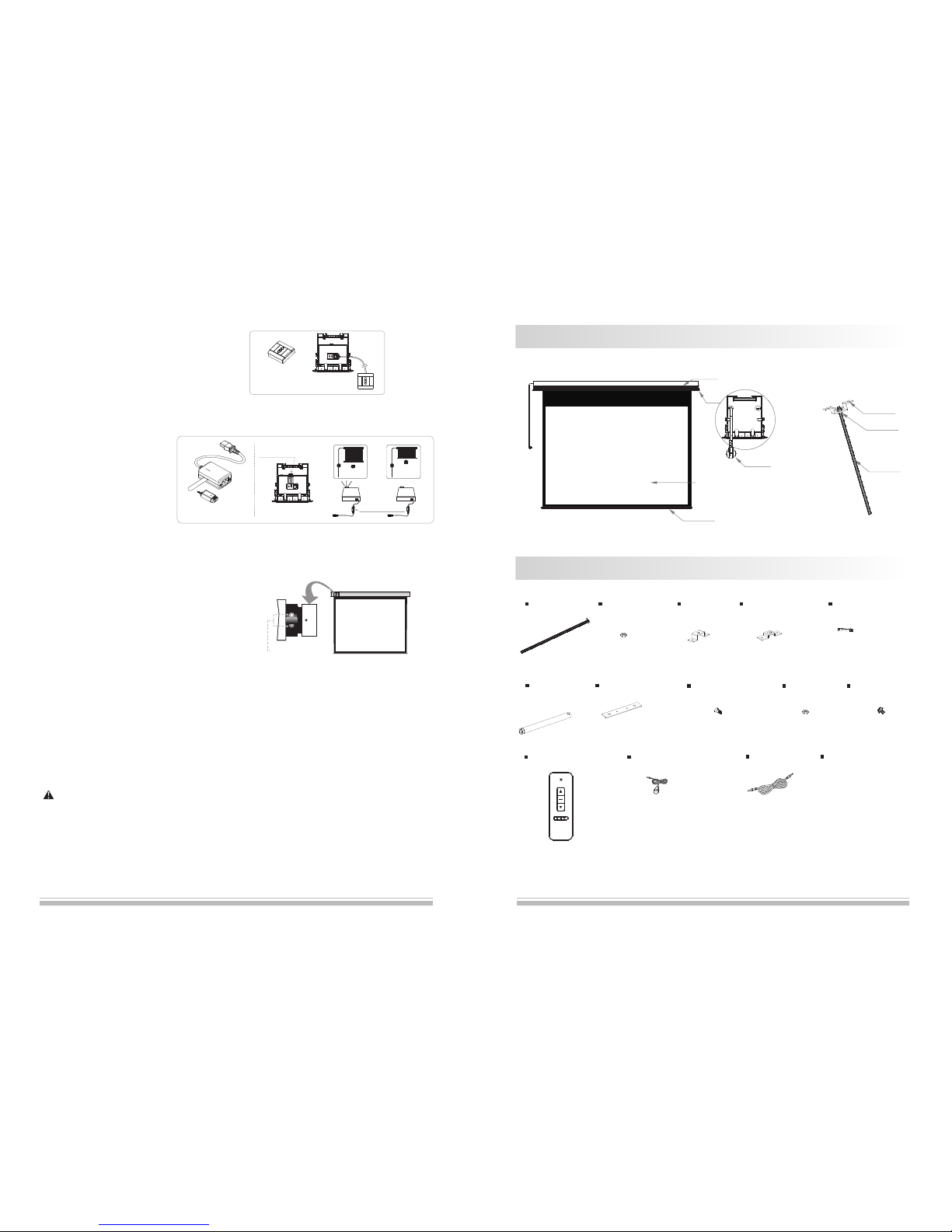
Mot or adju sting s lot
三. Scree n Adj ustme nt
(Pl ease ta ke apar t the baff le when a djust ing the s creen . And plea se rein stall t he baff le afte r adjus ting. )
Avo id the ov erhea ting of m otor; p lease d o not use t he scre en
ove r 4 secon ds for ex tendi ng and re tract ing con tinuo usly. The
mot or need s 4 minut es to col d down an d the mot or do not n eed
any l ubric ant. Th e stand ard fac tory se tting o f upper a nd lowe r
lim itati on is per fect. To av oid the d amage , pleas e conta ct the
pro fessi onal pe ople or l ocal de alers f or repa iring .
Motor P osi tio nin g
Ple ae adju st the mo tor adj ustin g slot us ing M4 al len key
“ ”
:
Scree n Ext end ing Adjust men t
Ope rate th e adjus tment w hen the s creen e xtend s compl etely
(1) F or adju sting t he view ing are a, plea se inse rt the ad justm ent to re gulat e adjus tment h ole. A cloc kwise
adj ustme nt will i ncrea se the vi ewing a rea for a bout 13 mm.
Not e: After p ressi ng the Up b utton , you wil l need a fe w secon ds to see t he adju stmen t of scre en; and a fter
pre ssing t he down b utton , you wil l see the p ositi on chan ged of sc reen.
(2) W ith the o ver-a djust ment, a c ounte r-clo ckwis e adjus tment w ill ret urn the s creen . This ad justm ent can b e
ope rated w hen the s creen s tops at t he lowe st post ion wit hout co ntrol ling.
Ple ase be ca reful w hile op erati ng, too m uch ret racti ng will c ause th e damag es of scr een and m otor.
E. Sync hro P owe r Rel ay(op tio nal )
Aft er conn ectin g the Wir eless S ynchr o
Con verte r, the scr een can b e contr olled
by FM m odula tion wi reles s contr oller
whi ch can co opera te with S ychro P ower
Rel ay and sw itch of p rojec tor to co ntrol
the u p and dow n of scre en sync hrono usly.
D. Exte rna l Wall Swi tch ( opt ion al)
The w all swi tch is av ailab le for a fi xed loc ation . Pleas e
con nect RJ 11 plug to E XTCTR L inp ut on the s creen .
Not e: plea se use a co rd for a fa r locat ion.
Wall S witch
(op tiona l)
Scree n Ret rac tin g Adju stm ent
Ref erenc e:
(No te: Thi s adjus tment i s not saf ety, plea se cont act the p rofes siona l peopl e for rep airin g and avo id dama ging of
scr een and w arran ty fail ure)
Cau tion we st rongl y recom mend th at do not r egula te the sc reen li mitat ion pri vatel y. The s tanda rd limi tatio n of
scr een is se t from th e facto ry and th is stan dard ca n satis fy the re quire ment of u sers.
“ ”
“ ”
2
Scr een Fab ric
Alu minum C asing
Low B ar
M12 N ut (12p cs)
M12 B ar (4pcs)
M12 B ar
M12 N ut
Hoo k
Bra cket
Fro nt View
Hoo k (4pcs ) Pre ssing P iece (2 pcs)
Wren ch (1pc )
M10 X100 Ex pansi on
Scr ew (8pc s)
Han ging Bo ard (2p cs)
M6 All en Scre w (4pcs )
M6 Nu t (4pcs )
M5 Sc rew (4p cs)
Ins truct ion Man ual (1p c)
Infra red R emote C ontro ller (1 pc)
Ext ernal I nfrar ed Rece iver (1 pc)
Trig ger Lin e (1pc)
Syc hro Pow er Rela y and
Wir eless S ynchr o Conve rter
IR to R F recei ver
Pow er Sync hro
and I R
Sid e View
Po we r l in e
Descr iption
Accessaries
“ “
“ “
Page 4
3
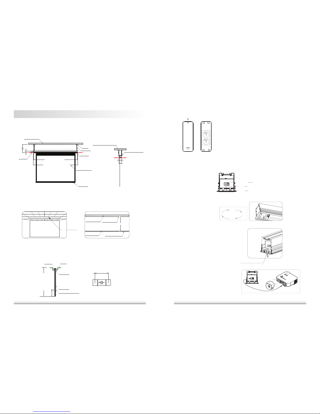
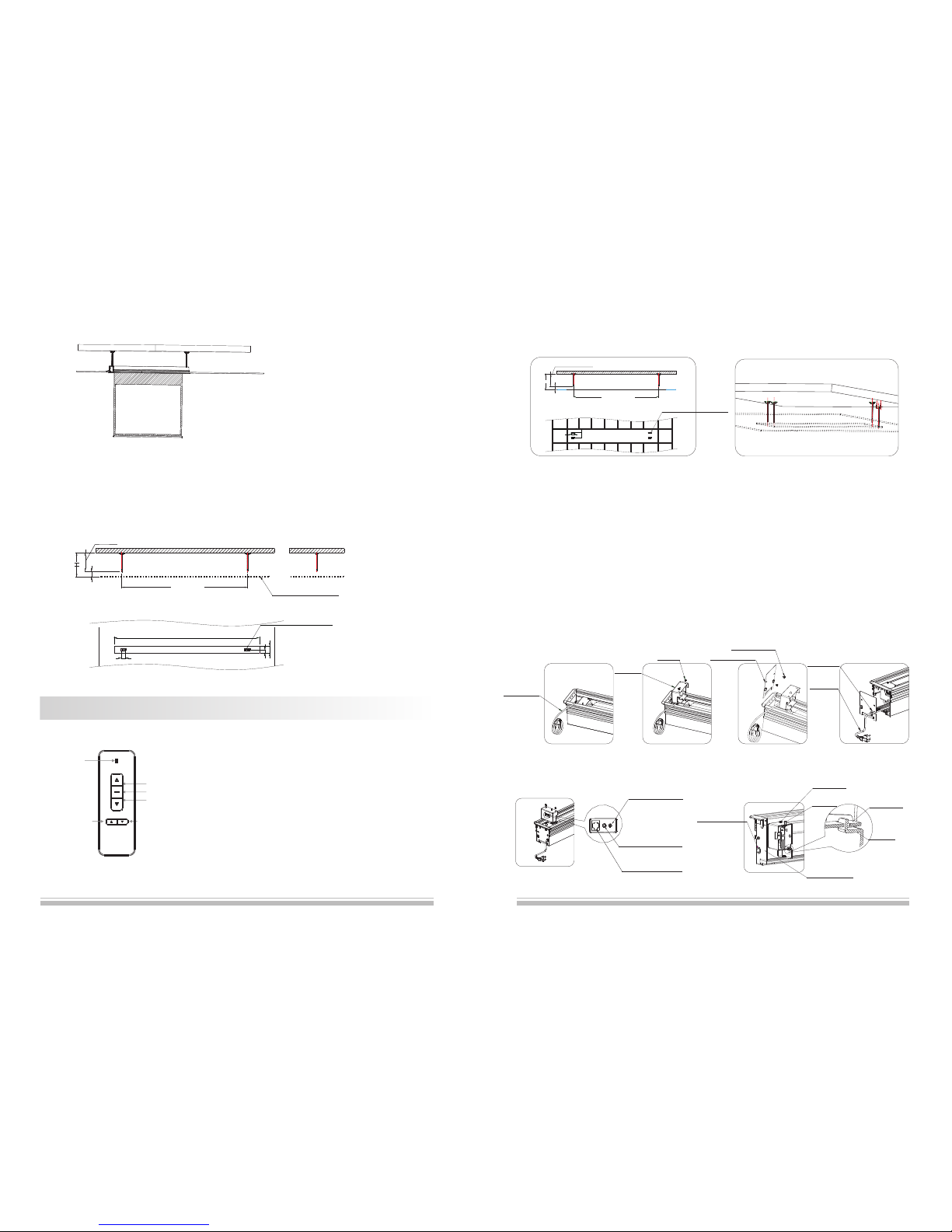
1.Ch oose a po sitio n accor ding to t he requ ired sp ace, an d then ta ke apar t the cei ling (f igure 1 ). Plea se meas ure the
dis tance H b etwee n concr ete roo f and cei ling su rface c orrec tly (fi gure 2) .
一. Grill e- Ceili ng Moun t
Take ap art the c eilin g
Figur e 2
Con crete R oof
Roo f Surfa ce
Cei ling Su rface
Gri lle-c eilin g
Figur e 1
H
2.Th is scre en equi ps brac ket, an d build u p the han ging br acket u sing th e hook, M 12 nut an d M12 bar. C ut the le ngth
of M1 2 bar to H mi nus 100 mm(H is t he dist ance be tween c oncre te roof a nd ceil ing sur face) ( Note: H i s 500mm , the
len gth of ha nging b racke t is 400m w hich is 5 00mm mi nus 100 mm) (fi gure 3) .
figur e 3
Cei ling
Con crete R oof
Low B ar
L minu s 26mm
( )The w idth of g roove
L( )The l ength o f scree n
M12 B ar
Scr een
Scr een Fab ric
Hoo k
100
Han ging Bo ard
Thi s numbe r of bars c an
be fo ur and tw o accor ding
to di fferen t insta llati on.
158( )T he widt h of groo ve
170( )T he leng th of scr een
12
二. External Control System
Fou r contr ol syst ems are a vaila ble
for m otori zed scr een
(1)M anual C ontro l
(2)I nfrar ed Remo te Cont rol (IR )
(3)D ry Cont act
(4)S witch
EXT CTRL
TRIG
EXT IR
Trig ger
Dry C ontac t/RS2 32
Ext ernal I nfrar ed Rece iver
B. Infr are d Rem ote C ontro l:
Bec ause of t he rece ssed mo unt, th e
ext ernal i nfrar ed EXT lr in put mus t be in
ser ted by ex terna l infra red rec eiver, t hen
ple ase fix i t in eyes f or cont rol.
Ext ernal I nfrar ed Inpu t
A.Manu al Co ntr ol:
The m anual c ontro l butto n is unde r
pow er box:
(Cl ose to po wer lin e)Cycl ic Cont rol
Cyc lic Con trol
Up
Sto p
Dow n
Sto p
C. Trigg er :
1. Pl ease co nnect 2 ,5mm pl ug of tri gger to
the T RIG inp ut on the s creen ; conne ct 3.5m m
plu g to the ou tput on t rigge r (only f or the eq uip
men ts whic h have tr igger f uncti on)
2. Th e proje ction s creen w ill aut omati cally
low er when t he proj ector i s on. It wi ll auto matic ally
ret ract wh en the pr oject or is tur ned off
Trig ger Lin e
Pro jecto r
TRI GGER
Thi s scree n needs t o be rece ssed in to the ce iling , and thi s instr uctio n manua l shows u s the gri lle-c eilin g and
woo d-cei ling as e xampl e. Plea se inst all the s creen a ccord ing to di ffere nt appl icati ons. Thi s scree n needs t o be
rec essed a t the bes t viewi ng angl e in orde r to impr ove the i mage. Tak e out all t he part s from th e packa ging an d
fol low the a ccess ories g uidel ine to en sure yo u have al l parts .
M12 B ar
M12 N ut
Hoo k
Bro och
H 100 mmmin us
100. 0
Mz2 S crew (4 pcs)
App roxim ately
150 mm
Insta llation Instruction
Push dow n
Batter ies Installa tion Instruc tion:
When the s ignal of the Con troller is fai nt, please rep lace the batte ries
as follo w steps:
1.Reve rse Controll er to the back, pu sh down as the arr ow mark to open
the cove r.
2.Inst alltwo cells o f battery and se t the directio n of positive an d
negati ve electrode j ust like the cha rt shows.
3.Clos e the battery co ver.
Page 5
4
3.Pl ease me asure t he secu rity di stanc e betwe en hang ing bra ckets ( figur e 4), and f ix the ha nging b racke ts on the
cei ling us ing exp ansio n screw s (figu re 5).
4, Pl ease fo llow th e below s teps to i nstal l the pow er cord w hich re cessi ng in cas ing, an d plug in t he exte rnal in frare d recei ver
(be cause o f the rec essed m ount, t he exte rnal in frare d recei ver mus t be read y for con trol) .
1)Take o ut the po wer cor d (figu re 6).
2)Lo ose the s crews o f power b ox and ta ke out th e power b ox (not e: the po wer box m ust be bu ttone d on the ha nger of b racke t
acc ordin g to figu re 11, plea se put up a nd move b ack the p ower bo x to take o ut), be cause t he powe r cord ha s a limit , pleas e do
not d raw it st rongl y.
3)Lo ose and t ake out t wo rubb er scre ws, the n remov e the end c ap (fig ure 8-9 ).
4)Re move th e line co ver of en d cap, th en fill i n the pow er line . Aft erwar d, stuc k the lin e cover b ack to en d cap, th en inst all the
pow er line o utsid e the cas ing.
5)In stall t he end ca p again ( figur e 10)
6)In sert th e exter nal inf rared r eceiv er to EXT IR h ole (fi gure 10 ) (note : pleas e put the c omple ted ext ernal i nfrar ed rece iver in to
ins ide fra me of scr een to av oid the p ressi ng from s creen ). Then in stall t he powe r box bac k to brac ket (no te: ens ure the p ower
box i s butto ned on th e hange r of brac ket) (f igure 11) .
figur e 4
figur e 5
TRIG( )Trigger
EXT IR()External
Infrared Receiver
EXT CT RL(
)
Dry
Con tact/ RS232
Figur e 10
Sig nal Out put
Swi tch
M4 Sc rew
Not e: the po wer box m ust be
but toned o n the han ger of br acket .
Bra cket
Pow er Box
End C ap Boar d
Figur e 11
Four Hangi ng
Boar ds are i n middl e.
100
H
L 94minus
H 100minus
180
100
Figur e6
Pow er Line
Figur e7 Figur e8 Figur e9
11
Pro duct Inst ruction
11. Ins talla tion Co mplet ed (fig ure 27) .
Not e: the up ward in struc tions a re only s uitab le for th e dista nce H whi ch betw een 200 -600m m; if the d istan ce is
gre ater th an 600m m, plea se foll ow the st eps as be low:
1)In stall t he hang ing bra cket at a r equir ed posi tion be fore ce iling f itmen t (M12 ba r is not pr ovide d) (fig ure 28) .
2)Sa w an oblo ng groo ve at a com plete d ceili ng (not e: plea se ensu re the ha nging b racke t must be i nstal led in th e
mid dle of th is groo ve) (fi gure 29 ). The re st of ste ps can fo llow th e instr uctio ns as bef ore!
Fig ure27
Fig ure29
Fig ure28
Two Ha nging
Boa rds are i n middl e.
L( ) 26m mTota l lengt h of scre en min us
Not c omple ted cei ling
H 100min us
100
L 94min us
158
79
Pow er Box
Scr ew
Rubbe r Scr ew
End C ap Boar d
Pow er Line
Line Cover
100
Button F unction and Op eration Inst ruction :
1.Pres s UP button to lift t he screen
2.Pres s STOP button to st op the screen
3.Pres s DOWN button to l ower the scree n
4.Pres s MICRO-UP butt on to retract th e screen in smal l
increm ents(150ms f or each moveme nt)
5.Pres s MICRO-DOWN b utton to lower t he screen in sma ll
increm ents (150ms fo r each movemen t)
Cautio ns:
1.The mi nimum distan ce between Con troller and Re ceiver: 50cm
2.Worka ble within 8m in h orizontal di rectionfro m the Receiver t o the
Contro ller
3.Do not c over the Contr oller’s lau nching port wh ile operatio n
4.Stri ctly banoper ation in wet or hi gh temperatu re environme nt.
5.Repl acing batter ies when the sig nal is faint or no s ignal.
6.Batt eries for the Co ntroller: 2 un its CR2032 but ton cells.
LED
UP
STOP
DOWN
Micro -up
Micro -down
Model :AC127
Page 6
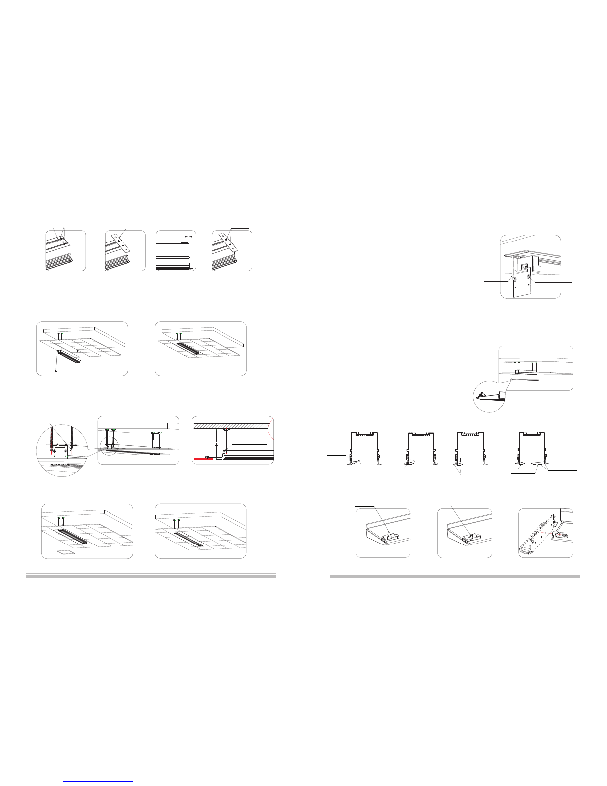
1) In sert th e baffle t o top gro ove.
Top Gro ove
2) St ay flat t he baffl e,
and c lip it to l ow groo ve.
Low G roove
Two su rface a t
the s ame lev el
3) Pr ess the b affle sl ightl y
and a lign it w ith cei ling bo ard.
4) The i nstal latio n of
lar ge baffl e is the sa me.
Lar ge Baffl e
Sma ll Baffl e
Two su rface a t
the s ame lev el
10
Not e: the up ward in struc tion sh ows us in stall ation o f exter nal con trol sy stem, i f the use rs want t o add oth er cont rol
sys tems, p lease f ollow t he step s as belo w:
1)Lo ose the s crews o f power b ox and ta ke out th e power b ox (bec ause
the p ower co rd has a li mit, pl ease do n ot
dra w it stro ngly) . Then lo ose two r ubber s crews a gain, a nd remo ve the
end c ap (ple ase ens ure the p ower li ne is
fix ed), st ep 3 can be f ollow.
2)In sert th e contr ol syst em sign al line t o corre spond ing out put (fi gure 11) ,
and t ake out t he sign al line f rom con trol
sys tem sig nal lin e exit (f igure 1 9).
3)Re insta ll the en d cap aft er comp leted c ontro l syste m and fas ten the
two r ubber s crews t hen rei nstal l the pow er box an d faste n two scr ews
acc ordin g to step 8 .
10. I nstal l the lar ge and sm all baf fle
1)Ple ase ens ure the s ecuri ty lock i s unloc ked (fi gure 20 a nd 22).
2)Ins tall th e large a nd smal l baffl e (figu re 21)
3)Unl ock the s ecuri ty lock o f baffl e (figu re 23), i nsert t he plug o f
sec urity t o a hole of e nd cap (f igure 2 4), if th e baffl e can not m ove
up th at plea se alig n baffl e with ce iling b oard.
Not e:
Rec essed m otori zed scr eens un der 120 ” utili ze both a l arge an d small
tri m cover. R ecess ed moto rized s creen s above a nd incl uding 1 20”
uti lize on ly one la rge tri m cover.
All Tab- tensi oned Re cesse d motor ized sc reens u tiliz e only on e large
tri m cover.
Fig ure21
Sig nal Lin e Exit
Fig ure22
Fig ure24
Fig ure25
Fig ure26
Fig ure23
5.Pl ease st ay the sc reen in t he oppo site di recti on, and f ix the le ft and ri ght han ging bo ard on th e scree n using
M6 sc rew and n ut (fig ure 12) .
6. In stall t he whol e scree n on the ha nging b racke t (figu re 13-1 4)
7. Fi x the scr een usi ng M12 nu t (figu re 15), t hen adj ust the s ecuri ty dist ance to H ( the dis tance b etwee n concr ete roo f and cei ling
sur face) u sing ad justi ng scre w. Loose t he M12 nu t and fix t he whol e scree n, and th en conn ect the p ower (f igure 1 6).
5
Fig ure13
fig ure 12
Fig ure15
Fig ure14
1)
in th e groov e of casi ng.
Sta y the M6 al len scr ew
2) In stall t he hang ing
boa rd
3) Pl ease en sure th e
dis tance b etwee n edge
of ha nging b oard an d the
edg e of casi ng is 5mm .
4) Fa sten th e hangi ng boar d
usi ng M6 nut , and ins tall ot her
han ging bo ard at th e same wa y.
Han ging Bo ard
Cas ing Gro ove
M6 All en Scre w
M6 Nu t
8. Cu t the sep arate d ceili ng boar d in a suit able si ze, whi ch can fi ll in the s ize of sp ace as sc reen (f igure 1 7-18) .
Fig ure18Fig ure17
Fig ure16
5.0
Unl ocked
Loc ked
M12 S crew (4 pcs)
M12 N ut
Pow er Line
"
"
Page 7
9
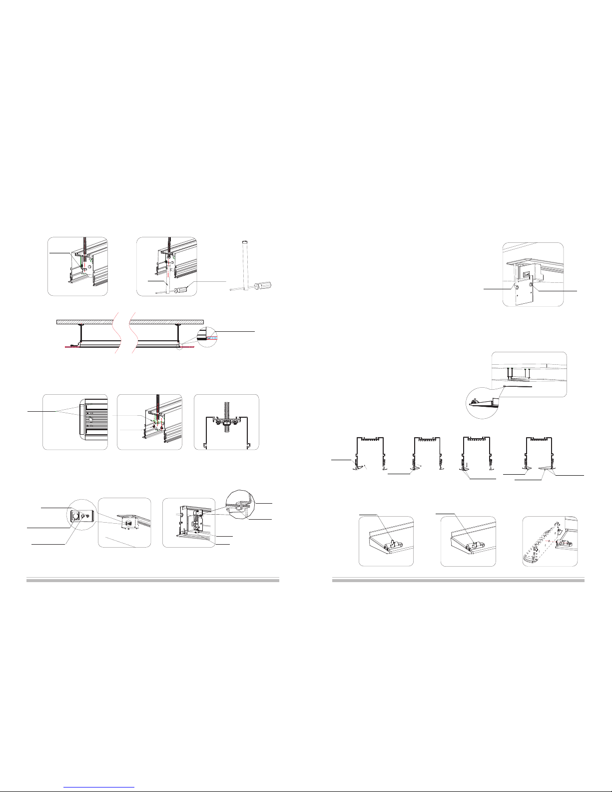
7.Pl ease en sure th e hexag on surf ace of nu t and ins ide sur face of c asing a re at the s ame lev el (fig ure 16) ; stay th e
pre ssing p iece on t he nut (f igure 1 7-18)
8. In sert th e exter nal inf rared r eceiv er to EXT I R hole(fi gure 18),
inf rared r eceiv er must b e ready f or cont rol, th en inst all the p ower bo x back to b racke t .
(no te: ens ure the p ower bo x is butt oned on t he hang er of bra cket) ( figur e 19).
bec ause of t he rece ssed mo unt, th e exter nal
Fig ure16 Fig ure18Fig ure17
Two su rface s are
at th e same le vel
Fig ure18
EXT CT RL
()
Dry
Con tact/ RS232
EXT IR(
)
External
Infrared Receiver
TRIG( )Trigger
Fig ure19
Fig ure15
M12 S crew
Wren ch
Not p rovid ed
(sc rewdr iver
can r eplac e)
Ali gn the or namen t
boa rd with c eilin g
Fig ure13
Fig ure14
Wren ch
Bra cket
But ton
Not e: the po wer box m ust be
but toned o n the han ger of br acket .
Pow er Box
Scr ew
1) In sert th e baffle
to to p groov e.
2) St ay flat t he baffl e,
and c lip it to l ow groo ve.
Low G roove
Two su rface a t
the s ame lev el
3) Pr ess the b affle sl ightl y
and a lign it w ith cei ling bo ard.
4) The i nstal latio n of
lar ge baffl e is the sa me.
Lar ge Baffl e
Sma ll Baffl e
Two su rface a t
the s ame lev el
6
10. I nstal l the lar ge and sm all baff le
1)Pl ease en sure th e secur ity loc k is unlo cked (f igure 2 0 and 22) .
2)In stall t he larg e and sma ll baffl e (figu re 21)
3)Un lock th e secur ity loc k of baffl e (figu re 23), i nsert t he plug o f secur ity to a
hol e of end ca p (figu re 24), i f the baff le can no t move up t hat ple ase ali gn
baff le with c eilin g board .
Not e:
Rec essed m otori zed scr eens un der 120 ” utili ze both a l arge an d
sma ll trim c over. Re cesse d motor ized sc reens a bove an d
inc ludin g 120” ut ilize o nly one l arge tr im cove r.
All Tab- tensi oned Re cesse d motor ized sc reens u tiliz e only on e
lar getri m cover.
Top Gro ove
Fig ure21
Fig ure22 Fig ure23 Fig ure24
Not e: the up ward in struc tion sh ows us in stall ation o f exter nal con trol sy stem, i f the use rs want t o
add o ther co ntrol s ystem s, plea se foll ow the st eps as be low:
1)Lo ose the s crews o f power b ox and ta ke out th e power
box ( becau se the po wer cor d has a lim it,
ple ase do no t draw it s trong ly). Th en lo ose t wo rub ber
scr ews aga in, and r emove t he end ca p
(pl ease en sure th e power l ine is fi xed), s tep 3 can b e follo w.
2)In sert th e contr ol syst em sign al line t o corre spond ing
out put (fi gure 11) , and t ake o ut the s ignal
lin e from co ntrol s ystem s ignal l ine exi t (figu re 18).
3)Re insta ll the en d cap aft er comp leted c ontro l syste m
and f asten t he two ru bber sc rews th en
rei nstal l the pow er box an d faste n two scr ews acc ordin g
to st ep 4.
Fig ure19
Fig ure20
Sig nal Lin e Exit
Unl ocked
Loc ked
6. Fi x the scr een usi ng M12 nu t, then f asten t he nut by w rench ( acces sorie s) (fig ure 13- 14); un til the o rname nt
boa rd alig n the cei ling (f igure 1 5) and co nnect t he powe r.
Pow er line
M5 Sc rew
Pre ssing P iece
Page 8

7
二. Woo d Ce iling
1. Sa w an oblo ng groo ve at a req uired p ositi on (fig ure 1); P lease m easur e the dis tance H b etwee n concr ete roo f
and c eilin g surfa ce corr ectly ( figur e 2).
Con crete R oof
Roo f Surfa ce
Cei ling Su rface
Wood C eilin g
H
L( ) 26mmTotal l ength o f scree n min us
1
5
8
m
m
Fig ure1 Fig ure2
11. In stall ation C omple ted (fi gure 25 ).
.No te: the l ength o f M12 bar i s 500mm . Pleas e prepa re the ba r your se lf if the d istan ce H (bet ween co ncret e roof
and c eilin g) is lon ger tha n 600mm .
Fig ure25
8
4, Pl ease fo llow th e below s teps to i nstal l the pow er cord w hich re cessi ng in cas ing .
1)Take o ut the po wer cor d (figu re 6).
2)Lo ose the s crews o f power b ox and ta ke out th e power b ox (not e: the po wer box m ust be bu ttone d on the ha nger
of br acket a ccord ing to fi gure 11, p lease p ut up and m ove bac k the pow er box to t ake out ), beca use the p ower
cor d has a lim it, ple ase do no t draw it s trong ly.
3)Lo ose and t ake out t wo rubb er scre ws, the n remov e the end c ap (fig ure 8).
4)Re move th e line co ver of en d cap, an d then fi ll in the p ower li ne. Afte rward , stuck t he line c over ba ck to end c ap,
the n insta ll the po wer lin e outsi de the ca sing (f igure 9 )
5) Pl ease co mplet e the ins talla tion of e nd cap an d faste n two rub ber scr ews; do n ot need t o insta ll the po wer box
at th is mome nt.
5. In stall t he whol e scree n on the ha nging b racke t (figu re 11-12 )
Figur e 4
Figur e 5
Fig ure9
Fig ure7 Fig ure8Fig ure6
Fig ure11 Fig ure12
3.Pl ease me asure t he secu rity di stanc e betwe en hang ing bra ckets ( figur e 4), and f ix the ha nging b racke ts on the
cei ling us ing exp ansio n screw s (figu re 5).
L( ) 26m mTotal l ength of screen minus
158
100
79
H 100minus
Pow er Line
图10
2.Th is scre en equi ps brac ket, an d build u p the han ging br acket u sing th e hook, M 12 nut an d M12 bar. C ut the le ngth of M 12 bar to
H min us 100m m(H is th e dista nce bet ween co ncret e roof an d ceili ng surf ace) (N ote: H is 5 00mm, t he leng th of han ging br acket i s
400 m which i s 500mm m inus 10 0mm) (f igure 3 ).
Figur e 3
M12 B ar
M12 n ut
Hoo k
Bro och
H 100 mmmin us
100. 0
L 94minus
100
H
Pow er Box
Scr ew
EXT IR
()Ext ernal
Inf rared R eceiv er
Power Line
Line Cover
Rub ber Scr ew
End C ap
Four Hangi ng
Boar ds are i n middl e.
 Loading...