

Page 1
Model:LF-PUxx
GRANDVIEW REPRODUCING GENUINE COLORS
GRANDVIEW REPRODUCING GENUINE COLORS
ISO9001:2000
International Certification
Tha nk you fo r purch asing a G randv iew pro jecti on scre en.
Bef ore use , pleas e read in struc tions c arefu lly. Afte r insta llati on, sto re inst ructi ons for f uture re feren ce.
Grandview Crystal Screen Canada Ltd.
#11- 3751 North Fraser Way,
Marine Way Business Centre,
Burnaby, BC, Canada V5J 5G4
Tel: 1-604-412-9777 Fax: 1-604-412-9796
Website: www.grandviewscreen.ca
Guangzhou Grandview Crystal Screen Co., Ltd.
P.O. 511400 Federal Ind. Zone No. 363, Yushan West Road,
Shiqiao, Panyu District, Guangzhou, Guangdong, China
Tel: +8620-8489-9499 Fax: +8620-8480-3343
Website: www.grandviewscreen.com
www.grandviewscreen.com.cn
Installation Guide for
Large-flat Series Prestige Permanent Cinema Screen
Page 2
1
6
List 2 on AA dist ance bet ween Top brac ket and Bottom b racket ( Ref. Fig ure 18)
Siz e(inc h)
4:3
16: 9
Dist.(mm)
Dist.(mm)
60"
72"
77"
80" 84" 92" 100 " 106 "
112"
135 "
120 " 150 "
1025 1208 1284
1330 139 1 1513
1726 1818 1940 2168
2397 1635
858 100 7 106 9 1107 1156 125 6
1356 1430
1505 1605 179 1 1978
4:3
16: 9
60"
72"
77"
80" 84" 92" 100 " 106 "
112"
135 "
120 " 150 "
20 20
24 24 24
26 28
30
30
32 34 38
18
22 22 22 24 24
28 28
30
30 34 38
Description
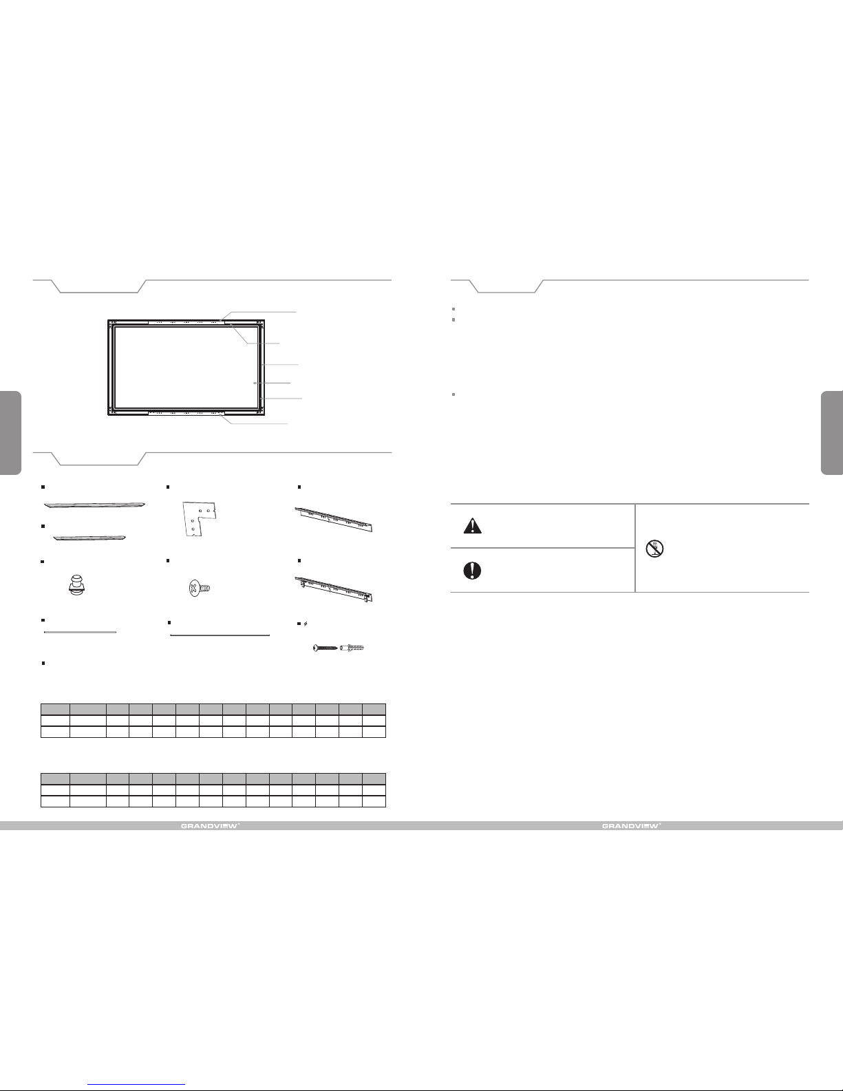
Accessories
Side fr ame
Horiz ontal fram e
Scree n fabric
Rem ark:Two ex tra Fix ing lug s for eac h scree n
Format
Siz e(inc h)
Qty (pcs)
Fixin g lug
Top bracket
Bottom bracket
Horizontal frame (2pcs)
Side frame (2 )pcs
Horizontal tensioning bar (2 )pcs
Side tensioning bar (2 )pcs
Fixing lug (Ref. list 1)
Cor ner b racke t (4 )pcs
5x1 0mm C orner scre w (16 )pcs
Instruction manual 1( pc)
Top bracket(1pc)
Bottom bracket (1pc)
Fixing lug list 1
Qty (pcs)
Format
Ignor ing the safe ty warning s may
le ad t o in juri es a nd/o r damaging
the pro duct.
Fixtures should be installed in a secure
place to avoid accidents or the screen
falling.
Pleas e contact yo ur local dea ler for
repairs or maintenance. Please contact
our company if you h ave any furth er
que stion s. Avoi d tak ing a part the
fix tures your self. Loos e part s may
cause t he screen to f all.
Warnings
Do not take apart and replace with unknown parts. If there are any problems, please contact your local dealer.
Product specifications are subject to change.
When in stalling , make sure it i s facing for ward. The bac k of the scree n will be labe led with a sti cker.
Pleas e read the fol lowing as an y damage to th e screen sur face will aff ect the qual ity of the pic ture:
1.The fr ame is made wi th lightwe ight alumi num. Pleas e handle wit h care.
2.Avoid c ontact or to uching the s creen surf ace as it may ca use scratc hes or tears .
3.Do not w rite or draw o n the surfac e.
4.Clean the screen wi th a soft cloth and lukewarm water. Do not use any detergent or cleaning prod ucts.
5.Use a co tton cloth t o carefull y wipe off the du st on the fram e to prevent a ny damages
6.If it is n ot in use for a lo ng period of t ime, cover t he screen to s hut out dust a nd dirt.
To prevent unnecessary damage , the operating and maintenance of the scree n should be done by adults.
Openi ng the case, t he frame has i ndentati ons on surfa ce because o f packagin g in a dry case fo r a long
time. Th is is a normal p henomeno n and the scre en can be used n ormally. Ple ase stay the s creen in a
norma l conditio n that the ind entation s can be natur ally remov ed. Recove ry time will b e changed in 1 -15
days be cause of the a ir humidit y, If you wa nt to remove t hese inden tations qu ickly, please u se half-we t
solut ion.
Metho ds: Sprink le water on th e surface th at can remov e the indent ations.
5x40 mm Tapping screw
with anchor (8 pcs)
Page 3
2
5
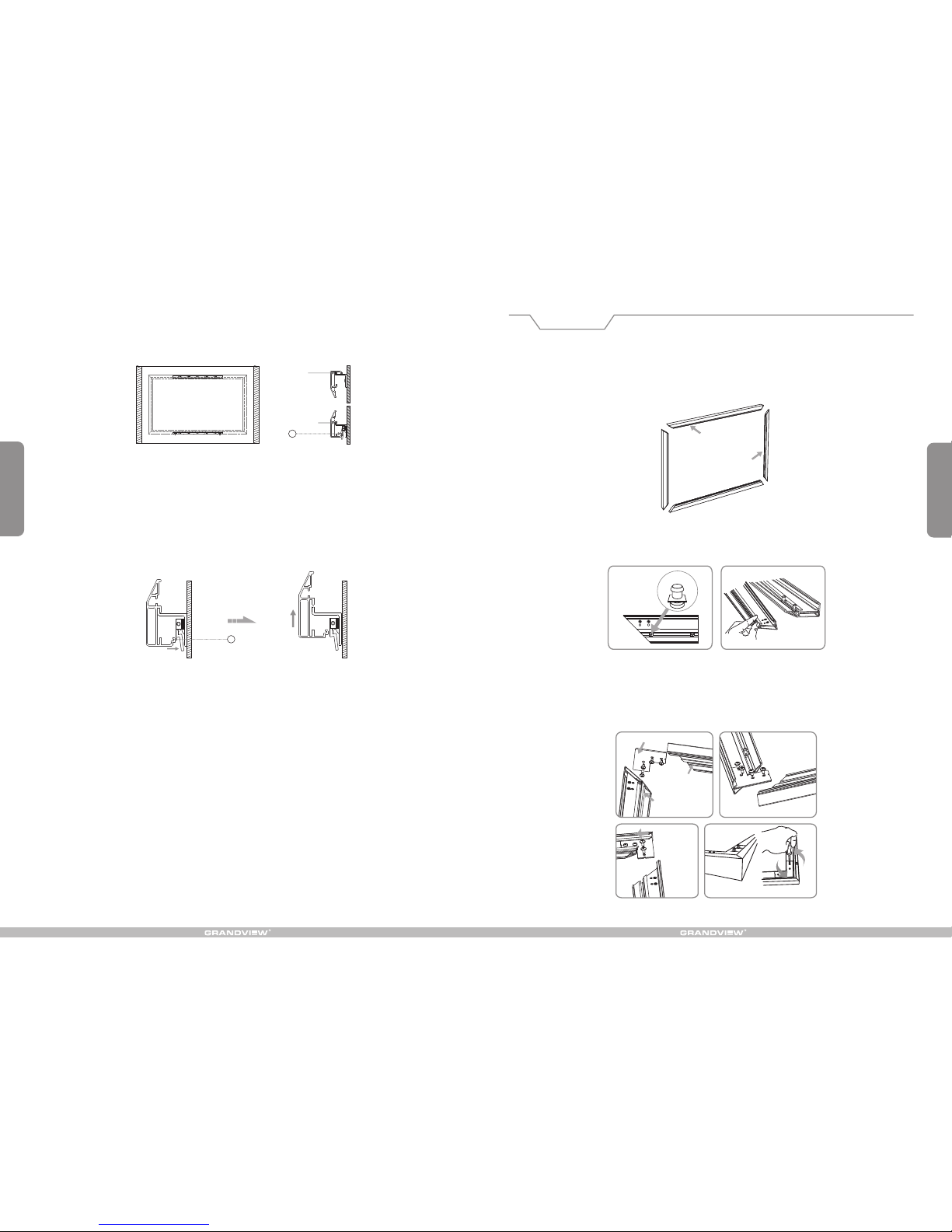
1. Locate Hori zontal frames and Side f rames on tidy flat surfa ce. (Figure 1)
2. Slide Fixin g lugs into grooves on rev erse side of frames and al ign with arrows. (Figu re 2-3)
Figure 1
3. Connect Hor izontal frame and Side f rame with Corner brack et, adjust the Corner br acket to match screw
holes on frame a nd Corner backet, then f ix with the Corner brack et screws. Same way to oth er 3 Corner
brackets ins talltion. (Figure 4- 7)
Corner
9. To tear down the screen, please press the Secure buttons towards wall to release bottom frame from
groove B, then uplift the screen little to release it totally from up groove & bottom groove of the brackets.
(Figure 23-24)
8. Uplift the assembled screen to make sure Up groove meet with Top bracket, and Down groove meet with
Bottom bracket, the Secure button would lock into Groove B because of spring tension when frames are
matched on brackets ideally. (Figure 21-22)
Up groove
Bottom groove
B
B
Take out all the parts from the p ackaging and follow the ac cessories guidelin e to ensure you have all par ts,
then install t he screen as below.
Installation
Side frame
Horizontal fra me
Figure 2 Figure 3
Fixing lug
Side frame
Horizontal frame
Figure 4 Figure 5
Figure 6
Figure 7
Figure 21 Figure 22
Figure 23 Figure 24
Page 4
3
4
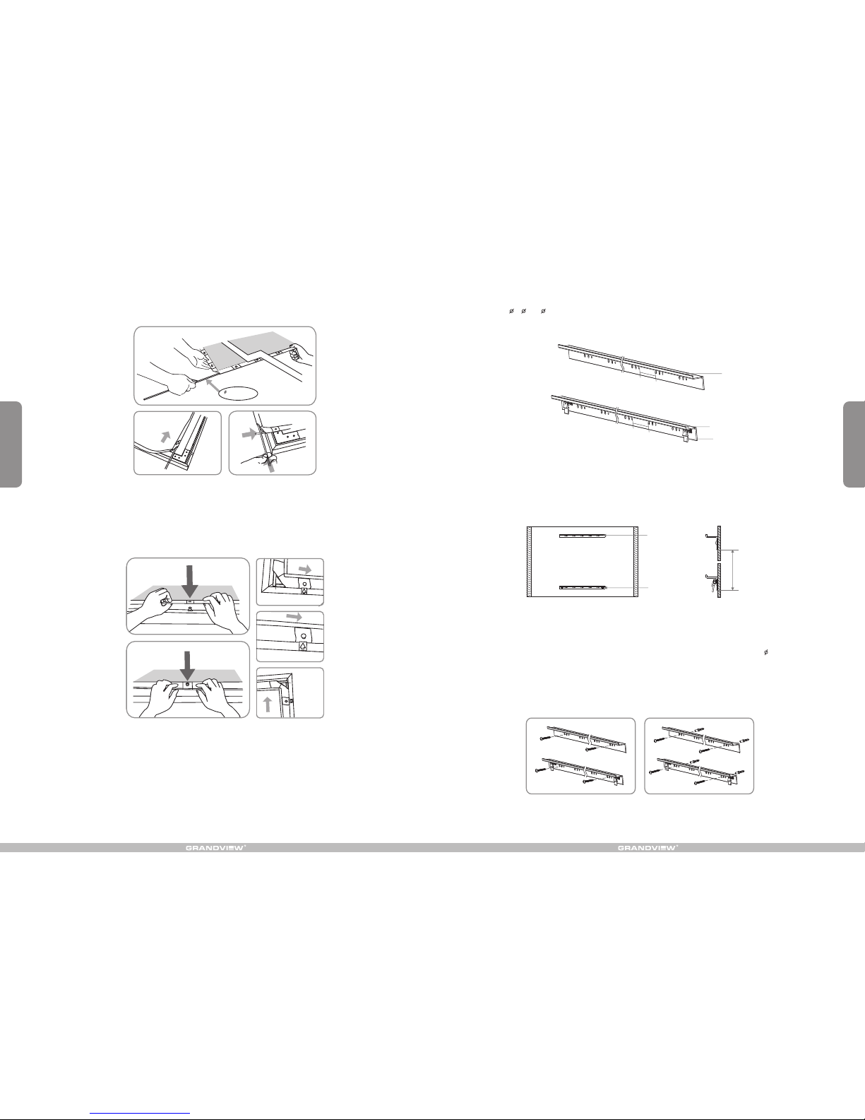
5. Double align Fixing lugs with arrows. Using the Tensioning bar, pull fabric eyelets over Fixing lugs by your
hands clockwise (Tips: arrange Horizontal tensioning bars first then Side tensioning bars). (Figure 11-15)
6. There is locking system on the Bottom bracket but no on the Top backet, brackets' length are at half of
Horizontal frames'. And there is 5 groups of holes on each brackets with 10cm distance, each group has
3 holes at 5 8 & 6 from left to right. Brackets are suggested to mount at the middle point of frame with
only 30% fluctuation if needed. (Figure 16)
Up bracket
Bottom bracket
Secure button
10
CM
10
CM
7. According to AA distance list on first page, mount two brackets onto the wall separately, assure they are at
horizontal level. (Figure 17-18)
Up br acket
Bot tom bra cket
AA
4. Unfold screen fabric and insert 4 Tensioning bars seperately into 4 different fabric grooves, be careful not
to poke the fabric. (Figure 8-10)
Figure 8
Figure 10
Figure 9
5mm Tensioning
bar
Figure 11
Figure 12
Figure 13
Figure 14
Figure 15
Figure 16
Figure 17 Figure 18
Here below are the mounting details:
a) Wood wall mounting: to fix the brackets onto the wall using 4 provided Wooden screws 5 x 40, two screws
for each brakcet. (Figure 19)
b) Concrete wall mounting: to use an electric drill to drill 4 holes ( 2 holes for each bracket), and hammer the
provided tapping anchors into each hole, then fix the brackets onto the wall by fastening the tapping screws
to the tapping anchors. (Figure 20)
Figure 19 Figure 20
 Loading...