

Page 1
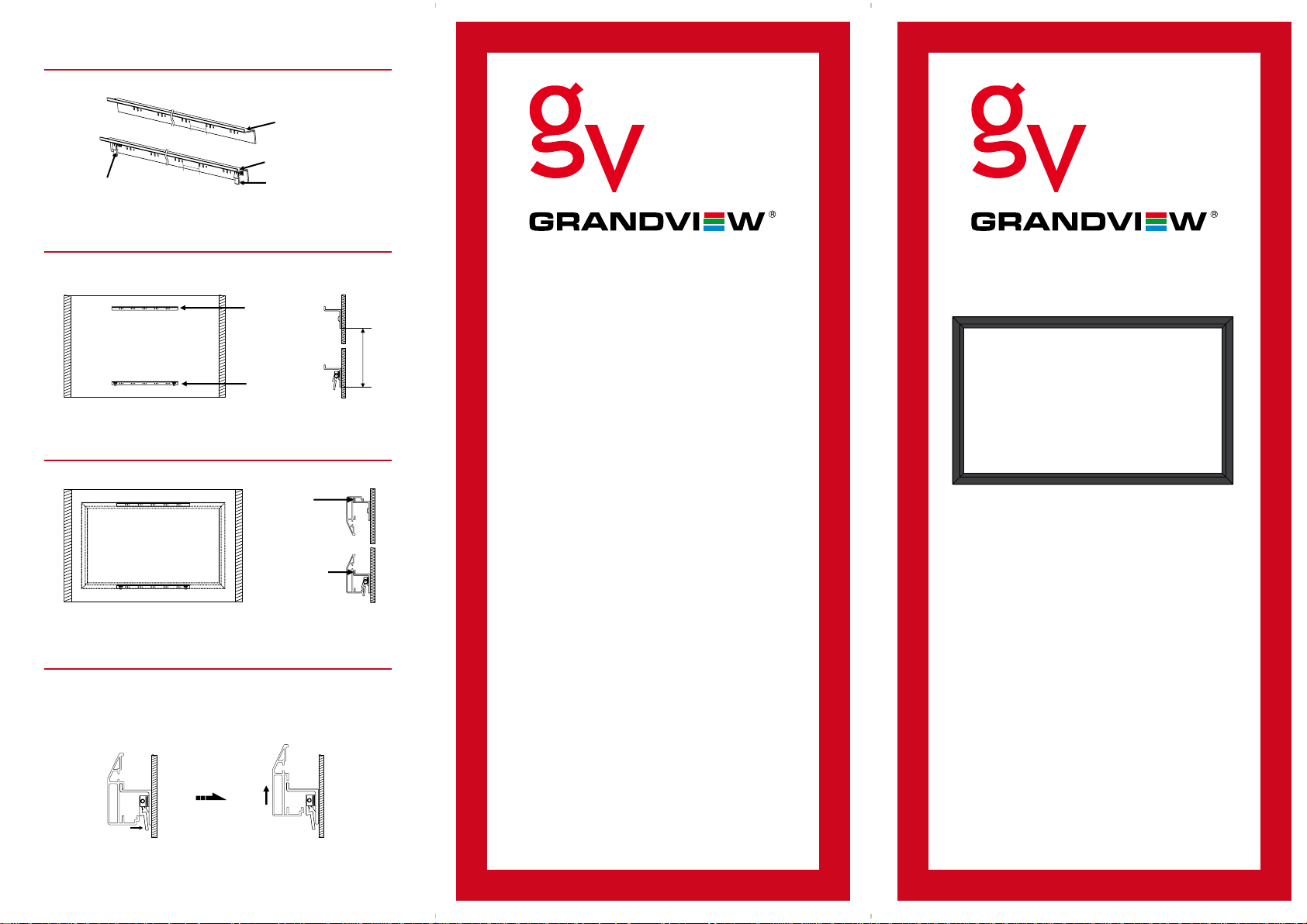
Step 6
There is a locking latch on the bottom wall mount only.
Up Bracket
Bottom Bracket
Locking Latch
Fig 16
Secure Button
Step 7
Fix the mounts onto the wall separately. (Fig 17-18)
(For 100” - height (h) = 1356mm & 115” - height (h) = 1542mm).
Up Bracket
h
Bottom Bracket
Fig 17 Fig 18
Step 8
Hook screen onto the top mount and bottom mount. (Fig 19-20)
Protecting Your Screen:
• Keep away from direct sunlight or
high temperatures.
• Examine both the front and back surfaces before
retracting into the case to make sure it is free of
dust, dirt, insects or other foreign matter.
• Use a soft brush or cloth to lightly remove any
foreign particles.
Cleaning Your Screen:
Fig 19 Fig 20
Step 9
To uninstall the screen, please press the latch towards the wall
to release bottom frame from bottom mount, then lift the screen
a little to release it totally from top and bottom groove of the
mounts. (Fig 21-22)
Fig 21 Fig 22
Happy Viewing!
• Do not use any solvents, chemicals or abrasive
cleaners on the screen surface.
• Use a mild detergent with warm water to remove
any marks on the surface or screen case.
• Always immediately dab the screen with a lint free
soft cloth to avoid soap marks.
• Do not scrub the surface.
Warranty: 12 Months
For more information please go to
www.projectisle.com.au
or call 1300 88 11 79
GV_Frame_Screen_Jul11 _v1.1
Grandview Flocked Frame
Screen User Manual
Page 2
Required (not supplied)
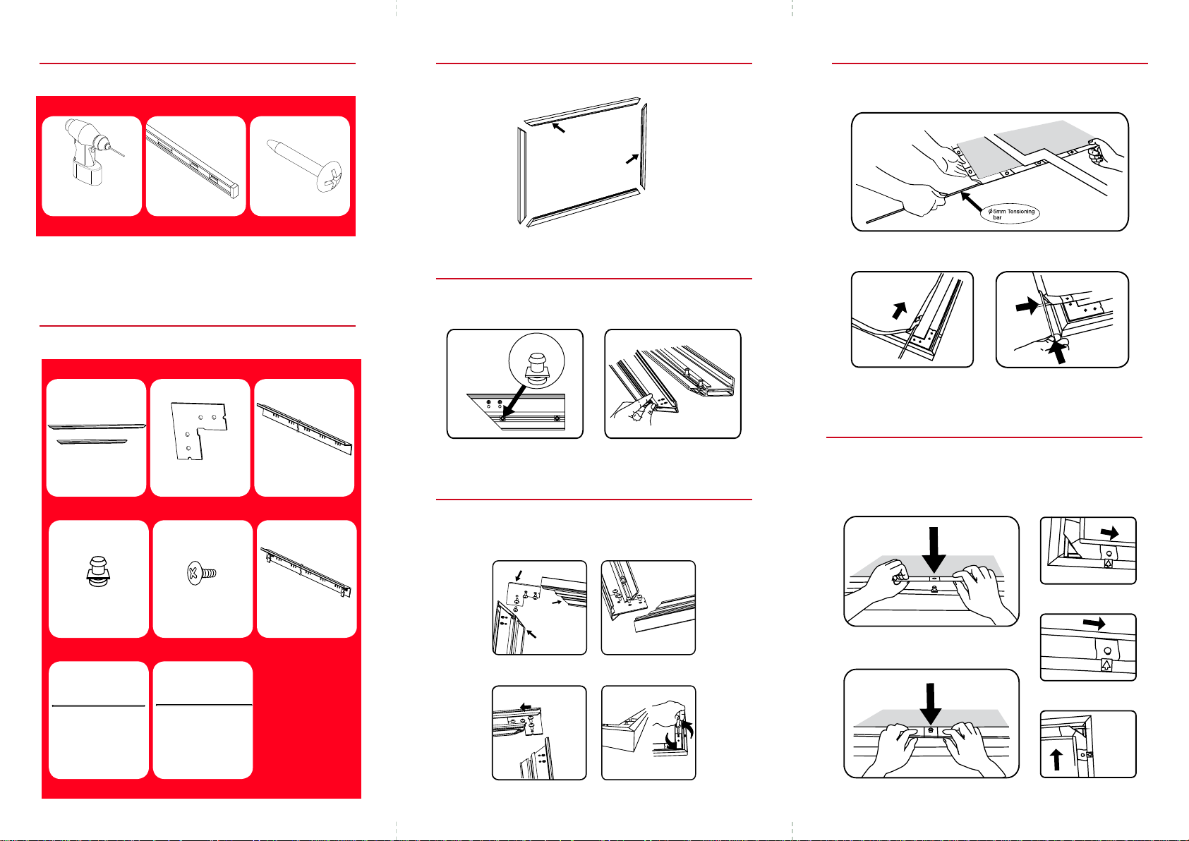
Step 1
Lay each section of the frames on a tidy flat surface. (Fig 1)
Horizontal Frame
Vertical Frame
Step 4
Unfold screen fabric and insert the tensioning bars into the fabric
grooves. (Fig 8-10)
Electric Drill
Screw Driver Level
Supplied parts
Horizontal Frame (x 2)
& Vertical Frame (x 2)
Fixing Lug
28 for 100”
30 for 115”
Corner Brackets
(x 4)
10mm Corner Screw
8 x Screws
to suit wall type
Top Mount (x 1)
Bottom Mount (x 1)
Fig 1
Step 2
Slide Fixing Lugs into grooves on the reverse side of frames.
(Fig 2 - 3)
Fixing Lug
Fig 3Fig 2
Step 3
Insert both horizontal and vertical frame sections with the corner
stakes. Ensure all joints are square and then lock off by
tightening with the screws provided. (Fig 4-7)
Corner
Horizontal
Frame
Vertical
Frame
Fig 4 Fig 5
Fig 8
Fig 9 Fig 10
Step 5
Align fixing lugs and the eyelets provided on the fabric. Using the
tensioning bar, pull fabric eyelets over the lugs. (Tip: Arrange
horizontal tensioning bars first then side tensioning bars).
(Fig 11-15)
Fig 13
Fig 11
Side Tensioning
Bar (x 2)
Horizontal Tensioning
Bar (x 2)
Fig 6 Fig 7
Fig 14
Fig 15Fig 12
 Loading...