

Page 1
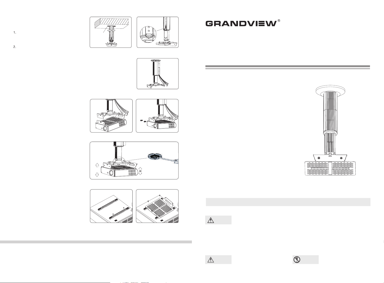
A. Please install GPC support bar
assembly on the ceiling
Fix the bas e o n the cei ling or con crete
(pl ease e nsu re that th e lo ad is 40kg at l east).
Fig ure 6
Ope n the b ack orna men t boa rd b, an d
lo osen the s crews of s ubsidia ry arm④
Ple ase adjust the subs idi ary arm④ t o y our
des ired positio n (t his fun ction is on ly f or
B20 0、 B30 0), and then faste n t he screws
again. Please hide the po wer line in to t he g ap
and clos e t he bac k o rname nt board③ b.
Fig ure 7 and Figure 8.
B.
Please connect the GPC support bar
③
assembly and GPM projector fixation
For inst all ing the complete d l ow bracket to
1.
the top bracke t⑦ that p ush up the comple ted
low bracket un til it is fixe d with the sec uri ty
loc k⑨ and fasten the scre ws,re fer to f igure9
and figure 1 0.
Ple ase ensure the GP C proj ect or fixation is
2.
fas tened .
Connecti on of p ower cord to p roj ector.
3.
Install th e bac k ornament b oar d.
4.
C. Adjust your desired angle.
Loose n t he screw s of GPC su pport ba r
1.
as sem bl y⑥
pro jecto r to your desired posi tio n and fasten
it. F igure 1 1
2.
The directio n of projecto r ca n be adjusted by
for ward 30° and backwar d 3°. Left a nd
rig ht adju stmen t is 3° .
vi a th e sp ann ed ; ad jus t t he
Installation for multifunctional arm
(optional accessories)
In stall t he mu ltifunc tional arm o n t he
1.
pro jecto r. Figu re 12
Adj ust the fixer a of mult ifu nctional arm for
2.
ali gning th e ins tal l hole of low br acket, and
the n faste n the screws. Fi gur e 13
Install o rna ment boar d⑩b for multifun cti onal
3.
arm.
⑩
⑩
GRANDVIEW REPRODUCING GENUINE COLORS
M6-M8 Expanding
Screw or Tapping
Screw
.
Figur e 6 Figur e 7
Instruction Manual
Figur e 8
⑧
Figur e 9 Figur e 10
3°
30°
Figur e 11
Figur e 12 Figure 13
3°
Projector Lift GPCM-C
Appli cable Model: GPCM-C Ser ies
Please read before using
Thank y ou for pur chasing our products.
Pl e ase re a d t h e i n st r uc t ion ma n ual
carefully i n orde r to ens ure this projector lift
is suitable f or your projection e quipment.
Cautious
Warnings
This in struction man ual is written fo r dealers and technicians.
The customer must employ the technicians for installation. Please process the
const ruction follo wing this instr uction manual to avoid injury caused by accidents.
For safety, the minimum load of ceiling must be 40KG
Grandview Crystal Screen Canada Ltd.
#11- 3751 N orth Fra ser Way,
Marin e Way Business Cen tre,
Burna by, BC, Cana da V5J 5G 4
Tel: 1-604-412-9 777 Fax: 1-604- 412-9796
Websi te: www.gr andvi ewscre en.ca
Guangzhou Grandview Crystal Screen Co., Ltd.
P.O. 511400 Fede ral Ind. Zone No. 3 63, Yushan We st Road ,
Shiqiao, Pan yu District, Gu angzhou, Guan gdong, China
Tel: +8620-8489- 9499 Fax: +8620 -8480-3343
Websi te: www.gr andvi ewscre en.co m
Caution
Pleas e do not incline the
proje ctor the extremely.
Do not
take apart
Pleas e do not take apart the
accessories of projector lift.
Page 2
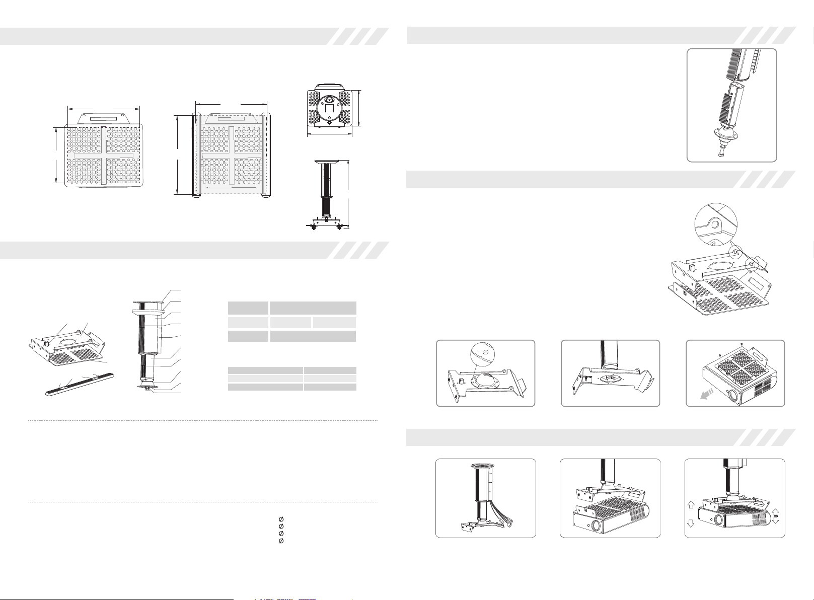
Diagram for applicable projector area
GPC
This projector lift must be installed above the bottom of projector (length 205mm; width 160mm).
Figure 1. Multifunctional arm is available for this projector lift and applicable projector area will be
increased (length 255mm; width 205mm)
180 mm
H
160mm
205mm
205mm
255 mm
Top View
255mm
Figure 1 Figure 2
Front View
Components and Accessories
GPCM-B is combined by GPC and GPM .
①
②
⑦
⑨
③
③a
③b
④
⑧
⑩b
⑩a
⑩
④a
⑤
⑤b
⑥
GPM
GPC
Spe cific ati ons
Model
Adjust distance
for each grid
Loa d
Optional Accessories
( )Support Bar、Multifunctional Arm
Pro duct Na me
The le ngth of s uppor t bar
Spec ifica tion fo r Multi funct ional A rm
GPC M-C
/
25k g
30x 355/3 0x295
Unit (mm)
16
Unit (mm)
Spe cific ation s
400 /600/ 800
Assembly
The main bar and the subsidiary bar are fixed tog ether from factory. Loosen
the screens of main bar③ and subsidiary bar④ . The distance between
proje ctor and ceiling can be adjusted according to the distance of install holes
betwe en main bar③ and subsidiary bar④ . Please refer to H in specification
table .
(Note: GPCM-C100 is no subsidiary bar and no stretch function).
③ ④
GPM
Assembly
1.GPM is combined by top bracket and low br acket . Press the
relea se button for separating the top bracket and low bracket.
2.The re are special security holes for avoiding the falling of
proje ctor (cooperate with security steel wire).
Usage
1. Press the release button for separating the top brac ket⑦ an d low
brack et⑧, refer to figure 3 and figure 4. Then, adj ust the half-cycle
junct ion⑤ and ensure that the groove of half-cycle junction to be
align the direction of security lock⑨ , and then put it on the
subsi diary bar after assembling. F inally, the glider is install ed on the
half- cycle junctio n for fastening the main bar⑥ as the figure.
2. Connect the projector and low bracket. Figure 5
Figure 3 Figure 4 Figure 5
⑦ ⑧
special
security holes
Parts :
① Base (1pc)
② Ornament Cover (1pc)
③ Main Bar (1pc)
③a Front Ornament Board
③b Back Or nament Board
④ Subsi diary Bar(1pc )
④a Ornament board for
subsidiary bar
Acces sories
M4x10 P ressin g Screw (4 pcs)
M4x5 Pr essing S crew (2p cs)
M4x5 Po sition ing Scre w (2pcs)
M3x10 C ross Mac hine Scr ew(4pc s)
M4x10 C ross Mac hine Scr ew(4pc s)
M5x10 C ross Mac hine Scr ew(8pc s)
M5x30 C ross Mac hine Scr ew(4pc s)
⑤ Half-Cycle Junction (1pc)
⑤b Glide r (1pc)
⑥ Main Screw (1pc)
⑦ Top Bracket (1pc)
⑧ Low Bracket (1pc)
⑨ Security Lock (1pcs)
M3x20 C ross Mac hine Scr ew(4pc s)
M4x20 C ross Mac hine Scr ew(4pc s)
M5x20 C ross Mac hine Scr ew(4pc s)
M3x30 C ross Mac hine Scr ew(4pc s)
M4x30 C ross Mac hine Scr ew(4pc s)
M6 Drop I n Anchor s(3 sets )
Optio nal Accessori es:
Multi functional Ar m
⑩ Multi functional Arm (2pcs)
⑩a Fixer (2pcs)
⑩b Ornam ent Board (8pcs)
16x10 R ubber In sert(4 pcs)
16x20 R ubber In sert(2 pcs)
Washe r(4pcs )
Sprin g Washer (4pcs)
Spann er (1pc)
Three steps for installation
A
A. Pl ease install GPC suppo rt
bar assembly on the ceiling
B. Pl ease connect the GPC
support bar assembly and
GPM projector fixation
B C
3°
30°
C. Ad just your d esired angle.
3°
 Loading...