

Page 1
GRANDVIEW REPRODUCING GENUINE COLORS
GRANDVIEW REPRODUCING GENUINE COLORS
Cyber Series Integrated Screen
With IR Remote Control
Grandview Crystal Screen Canada Ltd.
#11- 3751 No rth Fraser Way,
Marin e Way Busin ess Cent re,
Burna by, BC, Cana da V5J 5G4
Tel: 1-604- 412-97 77 Fax: 1-604- 412-9796
Websit e: www.grandvi ewscreen.c a
Guangzhou Grandview Crystal Screen Co., Ltd.
P.O. 511400 Feder al Ind. Zone No. 3 63, Yushan West Roa d,
Shiqi ao, Pany u District, Gu angzhou, Gua ngdong, Chin a
Tel: +8620- 8489-9 499 Fax: +8620 -8480-3343
Websit e: www.grandvi ewscreen.c om
ISO9001:2000
International Certification
Model:CB-MIxxⅡ
Thank you for purchasing a Grandview projection screen.
Before use, please read instructions carefully. After installation, store instructions for future reference.
Page 2
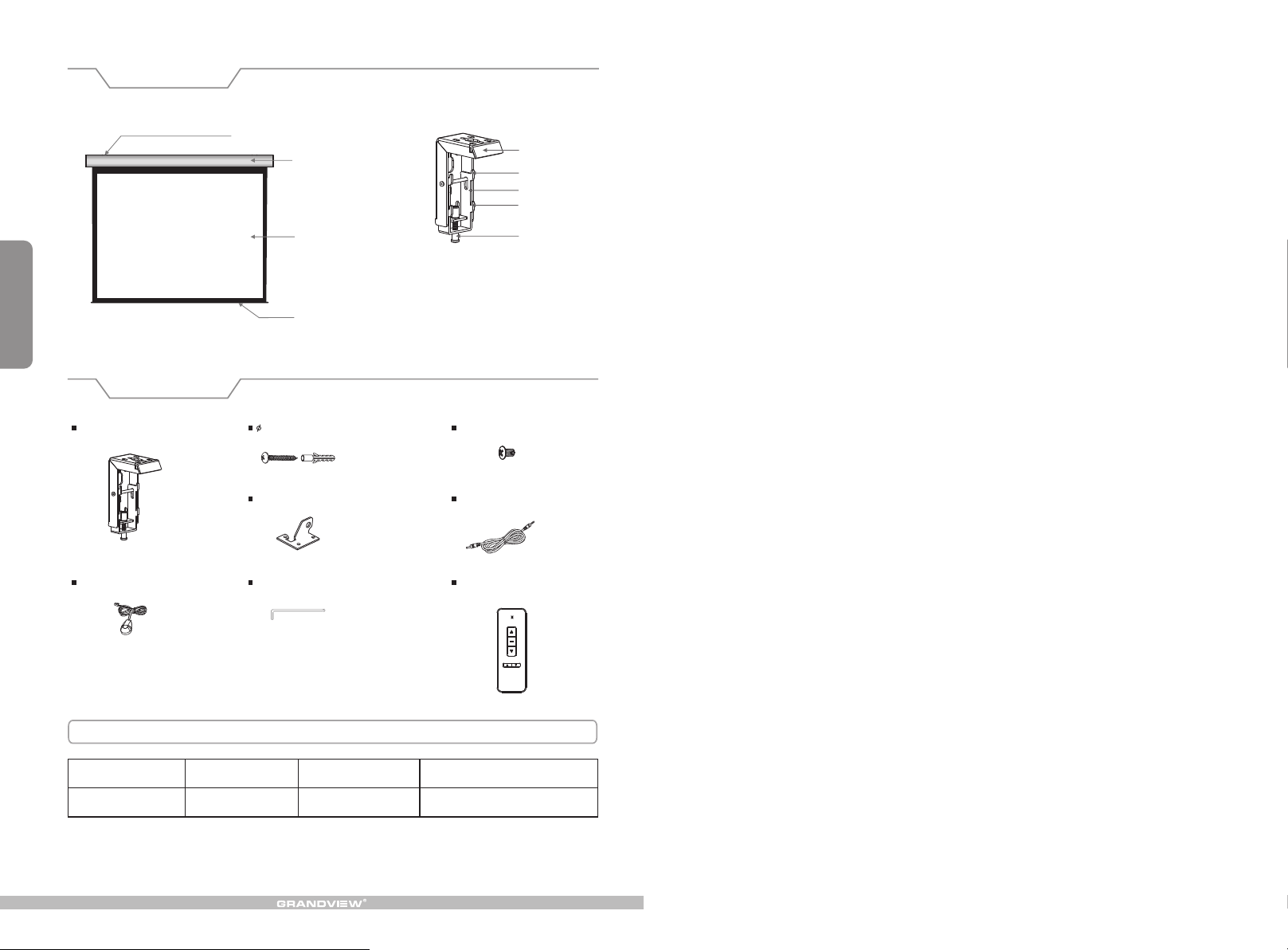
Description
Floating mounting bracket
Aluminum casing
Top panel
Upper groove
Locking piece
Lower groove
1
Accessories
Floating mounting bracket (2pcs)
External IR receiver (1 )pc
Screen fabric
Bottom Rod
5×40mm Tapping screw & cap (8sets)
Ceiling hanger (2pcs)
Allen key (1pc)
Locking screw
M5x10 Screw (6pcs)
Trigger line ( 1 pc )
Re
mote
Co
n
tro
ller
(1
pc
)
Motorized Screen Power Specifications
Voltag e Fre qu en cy
230V/1 20 V/100V
50Hz/6 0Hz 90W/8 0W
Wat ts
Appli ca tion
Applies to motorized screen up to 120"
Page 3
Warnings
The ceiling or wall used for fixture installation must be secure to prevent the screens from falling.
While installing electrical motors, please hire professionals or your local dealer to ensure safety. A misconnection
may lead to fire or leaks.
Make sure the Fixing screw be fastened when using the wall bracket, to avoid any damage.
Keep all infrared wireless products away from fluorescent lighting as it may cause malfunctions.
Please read the following as any damage to the screen surface will affect the quality of the picture:
1.Avoid contact or touching the screen surface as it may cause scratches or tears.
2.Do not write or draw on the surface.
3.Clean the screen with a soft cloth and lukewarm water. Do not use any detergent or cleaning products.
Roll up the screen after every use. Ensure that the screen is level when installing; do not pull on the sides or fold
the screen.
To prevent unnecessary damage, the operating and maintenance of the screen should be done by adults.
Installation
Take out all the parts from the package and following the accessories guideline ensure all the parts are there.
There are three different types of installation available for this product: wall mount, ceiling mount or ceiling hang.
Depending on the installation environment, the floating mounting brackets can be installed at various points for your
convenience. However, the ideal position for the mounting brackets is closer to the endcap as this will reduce
vibration and noise.
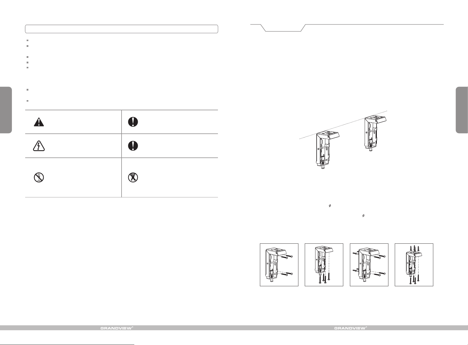
Wall and Ceiling Mount Installation
1.According to the surface of installation, choose the appropriate screws needed for mounting (regular screws for
wood surfaces, tapping screws for concrete surfaces)
2.Mount the brackets onto the surface, ensuring it is level (tip: draw a erasable level line when mounting the
brackets). See below for picture description (figure 1):
9
Ignoring the safety warnings may
lea d t o i njuries and /or damaging
the product.
Do n ot co nne ct a n y el ect ri cal
attachments o r re mote controls .
Please contact your local dealer for
repairs or maintenance. Please contact
our company if you have any further
questions. Avoid tak ing apart the
fixtures your self . Loose parts may
cause the screen to fall.
Do not take apart and replace with unknown parts. If there are any problems, please contact your local dealer.
Product specifications are subject to change.
Fixtures should be installed in a secure
place to avoid accidents or the screen
falling.
Roll up t he s cr ee n after e ve ry u se .
Leaving it ha ngin g for a long peri od
of time may cause the fabric to loosen.
Refrain from hanging anything on the
screen as it may cause the screen to
fall.
Figure 1
Installation Steps:
1.Wood wall and ceiling installation: Drill in the 5 x 40 screws through the appropriate holes in the bracket
(figure 2-3)
2.Drywall and ceiling installation: Install the anchors and drill in the 5 x 40 screws into the appropriate
bracket holes (figure 4-5)
Wood wall installation
Wood ceiling installation
Concrete wall installation
Concrete ceiling installation
2
Figure 2 Figure 3
Figure 4 Figure 5
Page 4
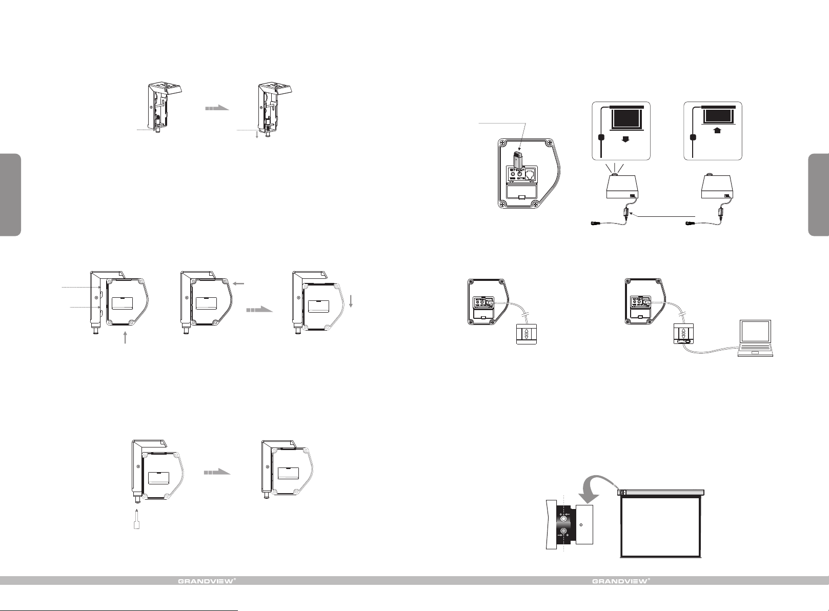
3.Loose n th e lo ck in g sc rew to lowe r th e lo ck in g pi ece down al l th e wa y (f ig ur e 6- 7)
Locking screw
Figure 6 Figure 7
Locking piece
Other Control Options Description
1.FM to IR control description:
When you insert the Wireless Synchro Converter Receiver into the EXTR slot of the control panel, you can use a
FM wireless remote control device. (figure 27). The Intelligent Synchro Power Supply Control Adaptor (for all
projectors) combined with the wireless 12V trigger (for all projectors with a trigger output) can control the screen
together. (figure 28-29)
Wir eless S ynchr o
Con verto r Recei ver
3
4.When mo un ti ng t he s cr een onto th e fl oa ti ng m ou nting bra ck et s, e ns ur e the grooves o n th e sc re en
casing ma tc h up w it h th e up per and low er g ro ve s on t he b rackets . Si mp ly s li de i n, and bracke t' s gr oo ve s
will hold t he c as in g in p la ce. Horiz on ta l ad ju st ments can s ti ll b e ma de ( fi gure 8-10).
Up gro ove
Down g roove
Fi gu r e 8 Fi gu r e 9
5.To lock the s cr ee n in p la ce , close and t ig ht en t he l oc king scre w on t he m ou nt in g brackets. T hi s wi ll keep
the scree n ca si ng l oc ke d firmly in p la ce ( fi gu re 11-12 ).
Figure 10
nte llige nt Sync hro Pow er
Sup ply Con trol Ada pter.
Figure 27 Figure 28 Fi gure 2 9
二 .Exte rn al Wall Swit ch
Figure 30 Figure 31
Manual control for screen up/stop/down.
Attention:
> Please make sure there is no dus t or dir t on the f abri c surface before rolling it back to the casing
> The rec omme ned working time is less than 50 seconds. The moto r will e nter o verheating protection
status and stop working for every co ntin uous 4 m inuters operation, user would need to wait for a
while until the motor cool dow n befo re ope rating again.
> There i s no lub e needed for the motor. Please be noticed that the appropriate setting is optimized
which requires no further ad just ment , plea se consult the after sales team before adjusting the limits.
Retraction Limit
三 .Exte rn al I ntelligen t Wall Switc h Co nn ection
1.Control for screen up/stop/down when connected to the
control panel interface of the screen.
2.Control for screen up/stop/down when connected to the
computer's RS232 or USB ingerface.
8
Figure 11
Figure 12
Drop Limit
Figure 32
Page 5
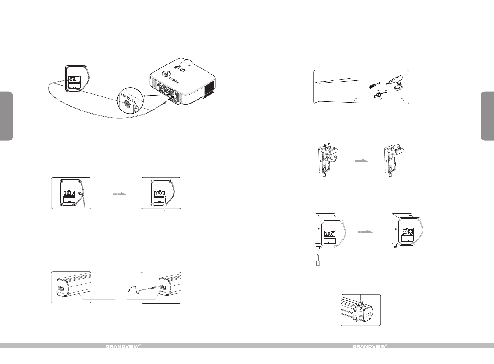
Automatic Trigger Control Description
1.Insert one end of the trigger wire into the trigger jack located on the left side of the screen casing's end cap
labeled “TRIG”. (figure 22). Insert the other end into the 12V output.
2.When the projector is powered on, the screen will lower automatically. When th projector is powered off, the
screen will retract automatically.
Ceiling Hang Installation
Choose ta pp in g sc re ws w ith hange rs ( or o th er s cr ews with ha ng er s, n ot p ro vided) acco rd in g to y ou r
ceiling m at er ia l. 5 x 4 0m m for wood ce il in gs a nd t ap ping scre ws f or c on cr et e ceilings ar e re co mm en de d.
1.Drill t wo i de nt ic al h oles with a n el ec tr ic al d rill and ensu re i t is h or iz on tal with th e
Wal l. F asten han ge rs ( no t pr ov ided) into th e ce il in g (f ig ure 13).
7
Pro jecto r
Figure 22
External Controls Description (Central Control or R232, Grandview Wall Switch)
Insert one end of the signal cord into the computer output jack located on the left side of the screen casing's end
cap and the other end of the signal cord to the central control jack, RS232 or Grandview wall switch. (figure 23-24).
You can then control the screen via central control or computer.
Figure 23
Figure 24
Infrared (IR) Remote Control Description
1.In order for the IR remote control to work, please ensure there is nothing covering the built-in sensor on the
screen casing.
For installations where the built-in sensor on the screen casing will be covered, use the external IR receiver
(provided) and insert it into the external IR slot on the screen casing's left end cap. Ensure the external IR
received head is in a position where it can received the remote control signal.
A
1
Figure 13
2.Use the M 5 x 10 s cr ew s pr ov ided in the a cc es so ry p ac kage to fix t he c ei li ng h an ger into the wa ll b ra ck et .
Ensure th e ti gh te ni ng s crews on th e wa ll b ra ck et a re tighte ne d an d se cu re . (figure 14- 15 )
Figure 14 Figure 15
3.After i ns er ti ng t he c eiling ha ng er, e ns ur e th e grooves o n th e ca se h ou si ng match up wit h th e mo un ti ng
bracket . To sec ur e the case ho us in g in to t he b rackets, ti gh te n th e lo cking screw s. ( fi gu re 1 6- 17)
Figure 16 Figure 17
2
4
Figure 23
External IR sensor
4.After c om pl et in g st eps 2 and 3, ch ec k to s ee w he th er the wall b ra ck et i s se cu rely fixe d on to t he h ou si ng
of the scre en b ef or e ha ng ing. Hang s cr ee n as s ho wn b elow. (fig ur e 18 )
External IR slot
Figure 24
Figure 18
Page 6
5
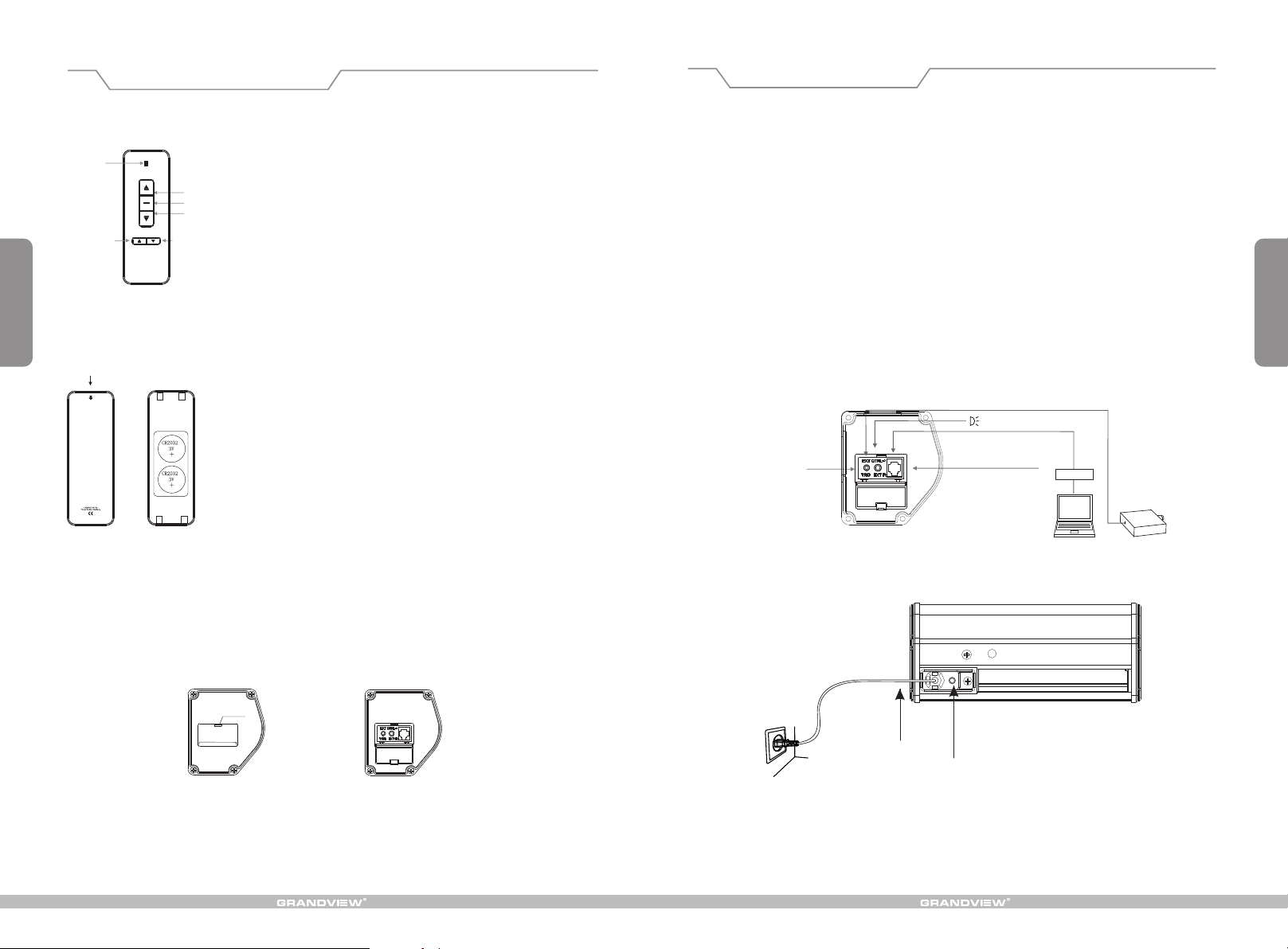
Remote Control Instruction
LED
UP
STOP
DOWN
Micro-up
Model:AC127
Push down
Micro-down
Button Function a nd Ope ration Instruct ion :
1.Press UP button to lift th e scre en
2.Press STOP button to stop the scr een
3.Press DOWN butt on to lo wer the screen
4.Press MICRO-U P butto n to ret ract the screen in sm all
increments(15 0ms fo r each movement)
5.Press MICRO-D OWN bu tton to lower the scr een in s mall
increments (150 ms for e ach movement)
Cautions:
1.The minimum dis tanc e between Control ler an d Receiver: 50cm
2.Wor kable within 8m in ho rizo ntal directionfrom th e Receiver to the
Controller
3.Do not cover the Co ntro ller ’s lau nchi ng port while opera tion
4.Strictly bano pera tion in wet or high tem pera ture environmen t.
5.Replacing bat teri es when the signal is f aint o r no signal.
6.Batteries for t he Con troller: 2 units CR 2032 b utton cells.
Operating Instructions
Connecting to an external power source:
1.Remove the glued on cloth on the bottom rod to ensure the rod is free from the casing.
2.Switch on the power. (with the appropriate voltage)
How to use the Manual/Remote Control Switch Button (Figure 20-21)
This motorized screen has 4 types on control options: infrared (IR) remote control, manual control, triggered control,
and external control (central control or RS232/USB).
Other Control Options (optional)
1.Convert the infrared control to a FM wireless control using the Wireless Synchro Converter Receiver.
2.Control using the Intelligent Synchro Power Supply Control Adaptor for inline control with the projector. Please
refer to specific manual instructions if options A and B are paired.
6
Batteries Insta llat ion Instruction :
When the signal of th e Cont roller is faint, pl ease r eplace the batter ies
as follow steps:
1.Reverse Contr olle r to the back, push dow n as the a rrow mark to open
the cover.
2.Installtwo ce lls of b attery and set the di rect ion of positive and
negative electr ode ju st like the chart sho ws.
3.Close the batte ry cov er.
Func tions
Press dow n an d op en t he e nd c ap lid to acc es s th e co nt ro l interfa ce . Wh en n ot i n us e, close to t he l id t o
conceal t he c on tr ol i nt erface.
End cap lid
Figure 19
Trig ger Jac k
Fig ure 20
Pow er cord
Switch control follows thi s priori ty: Down-Stop-Up-Stop-Down
Com puter O utput J ack
Man ual Con trol Sw itch
Con necti ng Exte rnal IR
RS2 32
Cen tral co ntrol ler
Figure 21
Pro jecto r
 Loading...