

Grandstream Networks, Inc.
UCM6510 IP PBX
User Manual

Firmware Version 1.0.2.5
UCM6510 IP PBX User Manual
Page 1 of 313
UCM6510 IP PBX User Manual
Index
CHANGE LOG ........................................................................................... 16
FIRMWARE VERSION 1.0.2.5 ............................................................................................................ 16
FIRMWARE VERSION 1.0.1.12 .......................................................................................................... 17
FIRMWARE VERSION 1.0.0.25 .......................................................................................................... 18
WELCOME ................................................................................................ 19
PRODUCT OVERVIEW ............................................................................. 21
FEATURE HIGHTLIGHTS ................................................................................................................... 21
TECHNICAL SPECIFICATIONS ......................................................................................................... 21
INSTALLATION ......................................................................................... 25
EQUIPMENT PACKAGING ................................................................................................................. 25
CONNECT YOUR UCM6510 .............................................................................................................. 25
CONNECT THE UCM6510 ........................................................................................................... 25
SAFETY COMPLIANCES ................................................................................................................... 27
WARRANTY ........................................................................................................................................ 27
GETTING STARTED ................................................................................. 29
USE THE LCD MENU ......................................................................................................................... 29
USE THE LED INDICATORS .............................................................................................................. 31
USE THE WEB GUI ............................................................................................................................ 32
ACCESS WEB GUI ...................................................................................................................... 32
WEB GUI CONFIGURATIONS ..................................................................................................... 33
WEB GUI LANGUAGES ............................................................................................................... 33
SAVE AND APPLY CHANGES ..................................................................................................... 34
MAKE YOUR FIRST CALL .................................................................................................................. 35
SYSTEM SETTINGS ................................................................................. 37
USER MANAGEMENT ........................................................................................................................ 37
USER PRIVILEGES ..................................................................................................................... 37
CREATE NEW WEB UI USER ..................................................................................................... 38
USER PORTAL ............................................................................................................................. 40
CONCURRENT MULTI-USER LOGIN ......................................................................................... 41
OPERATION LOG ........................................................................................................................ 41
CHANGE BINDING EMAIL .......................................................................................................... 43

Firmware Version 1.0.2.5
UCM6510 IP PBX User Manual
Page 2 of 313
NETWORK SETTINGS ....................................................................................................................... 44
BASIC SETTINGS ........................................................................................................................ 44
802.1X .......................................................................................................................................... 49
STATIC ROUTES ......................................................................................................................... 50
PORT FORWORDING ................................................................................................................. 53
DDNS SETTINGS ......................................................................................................................... 55
FIREWALL ........................................................................................................................................... 56
STATIC DEFENSE ....................................................................................................................... 56
DYNAMIC DEFENSE ................................................................................................................... 58
FAIL2BAN ..................................................................................................................................... 60
CHANGE PASSWORD ....................................................................................................................... 60
LDAP SERVER .................................................................................................................................... 61
LDAP SERVER CONFIGURATIONS ........................................................................................... 62
LDAP PHONEBOOK .................................................................................................................... 63
LDAP CLIEN T CONFIGURATIONS ............................................................................................. 66
HTTP SERVER .................................................................................................................................... 68
EMAIL SETTINGS ............................................................................................................................... 69
TIME SETTINGS ................................................................................................................................. 71
AUTO TIME UPDATING ............................................................................................................... 71
SET TIME MANUALLY ................................................................................................................. 72
OFFICE TIME ............................................................................................................................... 73
HOLIDAY ...................................................................................................................................... 74
NTP SERVER ...................................................................................................................................... 76
RECORDINGS STORAGE .................................................................................................................. 77
LOGIN TIMEOUT SETTINGS ............................................................................................................. 79
PROVISIONING ......................................................................................... 81
OVERVIEW ......................................................................................................................................... 81
CONFIGURATION ARCHITECTURE FOR END POINT DEVICE ...................................................... 81
AUTO PROVISIONING SETTINGS .................................................................................................... 82
DISCOVERY ........................................................................................................................................ 85
GLOBAL CONFIGURATION ............................................................................................................... 86
GLOBAL POLICY ......................................................................................................................... 86
GLOBAL TEMPLA TES ................................................................................................................. 93
MODEL CONF IGURATION ................................................................................................................. 96
MODEL TEMPLA TES ................................................................................................................... 96
MODEL UPDATE .......................................................................................................................... 98
DEVICE CONFIGURATION ................................................................................................................ 98
CREATE NEW DEVICE ................................................................................................................ 98
MANAGE DEVICES ..................................................................................................................... 99
SAMPLE APPLICATION .................................................................................................................... 106

Firmware Version 1.0.2.5
UCM6510 IP PBX User Manual
Page 3 of 313
EXTENSIONS .......................................................................................... 111
CREATE NEW USER ........................................................................................................................ 111
CREATE NEW SIP EXTENSION ................................................................................................111
CREATE NEW IAX EXTENSION ............................................................................................... 117
CREATE NEW FXS EXTENSION .............................................................................................. 122
BA TCH ADD EXTENSIONS .............................................................................................................. 126
BATCH ADD SIP EXTENSIONS ................................................................................................ 126
BATCH ADD IAX EXTENSIONS ................................................................................................ 129
SEARCH AND EDIT EXTENSION .................................................................................................... 132
EXPORT EXTENSIONS .................................................................................................................... 133
IMPORT EXTENSIONS..................................................................................................................... 133
EMAIL TO USER ............................................................................................................................... 134
ANALOG TRUNKS .................................................................................. 137
ANALOG TRUNKS CONFIGURATION ............................................................................................. 137
PSTN DETECTION ........................................................................................................................... 140
ANALOG HARDWA RE CONFI G URATION ....................................................................................... 144
DIGITAL TRUNKS ................................................................................... 147
DIGITAL HARDWARE CONFIGURATION ........................................................................................ 147
DIGIT A L TRUNK CONFIG URATION ................................................................................................. 157
DIRECT OUTWARD DIALING (DOD) VIA DIGITAL TRUNKS .......................................................... 158
DIGITA L T RUNK TRO UBLES HOOTING .......................................................................................... 158
DATA TRUNK .......................................................................................... 161
VOIP TRUNKS ......................................................................................... 163
VOIP TRUNK CONFIGURATION ...................................................................................................... 163
DIRECT OUTWARD DIALING (DOD) VIA VOIP TRUNKS ............................................................... 173
SLA STATION .......................................................................................... 175
CREATE/EDIT SLA STATION ........................................................................................................... 175
SAMPLE CONFIGURATIO N ............................................................................................................. 176
CALL ROUTES ........................................................................................ 179
OUTBOUND ROUTES ...................................................................................................................... 179
INBOUND ROUTES .......................................................................................................................... 181
INBOUND RULE CONFIGURATIONS ....................................................................................... 182
INBOUND ROUTE: PREPEND EXAMPLE ................................................................................ 184
BLACKLIST CONFIGURATIONS ............................................................................................... 185

Firmware Version 1.0.2.5
UCM6510 IP PBX User Manual
Page 4 of 313
CONFERENCE BRIDGE ......................................................................... 187
CONFERENCE BRIDGE CONFIGURATIONS .......................................................................... 187
JOIN A CONFERENCE CALL .................................................................................................... 189
INVITE OTHER PARTIES TO JOIN CONFERENCE ................................................................. 189
DURING THE CONFERENCE ................................................................................................... 190
RECORD CONFERENCE .......................................................................................................... 191
IVR ........................................................................................................... 193
CONFIGURE IVR .............................................................................................................................. 193
CREATE IVR PROMPT ..................................................................................................................... 195
RECORD NEW IVR PROMPT ................................................................................................... 195
UPLOAD IVR PROMPT ............................................................................................................. 196
LANGUAGE SETTINGS FOR VOICE PROMPT .................................... 197
DOWNLOAD AND INSTALL VOICE PROMPT PACKAGE ............................................................... 197
VOICEMAIL ............................................................................................. 201
CONFIGURE VOICEMAIL ................................................................................................................ 201
ACCESS VOICEMAIL ....................................................................................................................... 202
VOICEMAIL EMAIL SETTINGS ........................................................................................................ 203
CONFIGURE VOICEMAIL GROUP .................................................................................................. 205
RING GROUP .......................................................................................... 207
CONFIGURE RING GROUP ............................................................................................................. 207
REMOTE EXTENSION IN RING GROUP ........................................................................................ 209
P AGING AND INTERCOM GROUP ........................................................ 211
CONFIGURE PAGING/INTERCOM GROUP .................................................................................... 211
CALL QUEUE .......................................................................................... 213
CONFIGURE CALL QUEUE ............................................................................................................. 213
EXTENSION GROUPS ............................................................................ 217
CONFIGURE EXTENSION GROUPS .............................................................................................. 217
USE EXTENSION GROUPS ............................................................................................................. 217
PICKUP GROUPS ................................................................................... 219
CONFIGURE PICKUP G ROUPS ...................................................................................................... 219
CONFIGURE PICKUP F EATURE CODE .......................................................................................... 219

Firmware Version 1.0.2.5
UCM6510 IP PBX User Manual
Page 5 of 313
MUSIC ON HOLD .................................................................................... 221
FAX/T.38 .................................................................................................. 223
CONFIGURE FAX/T.38 ..................................................................................................................... 223
SAMPLE CONFIGURATIO N TO RECEIVE FAX FROM PSTN LINE ............................................... 224
SAMPLE CONFIGURATIO N FOR FAX-TO-EMAIL .......................................................................... 226
ASTERISK MANAGER INTERFACE (RESTRICTED ACCESS) ............ 227
FOLLOW ME ........................................................................................... 229
ONE-KEY DIAL ....................................................................................... 231
DISA ........................................................................................................ 233
CALLBACK FEATURE ........................................................................... 235
BLF AND EVENT LIST ............................................................................ 237
BLF .................................................................................................................................................... 237
EVENT LIST ...................................................................................................................................... 237
DIAL BY NAME ....................................................................................... 241
DIAL BY NAME CONFIGURATION................................................................................................... 241
ACTIVE CALLS AND MONITOR ............................................................ 245
ACTIVE CALLS STATUS .................................................................................................................. 245
HANG UP ACTIVE CALLS ................................................................................................................ 246
CALL MONITOR ................................................................................................................................ 246
CALL FEATURES ................................................................................... 249
FEATURE CODES ............................................................................................................................ 249
CALL RECORDING ........................................................................................................................... 253
CALL PARK ....................................................................................................................................... 253
P ARK A CALL ............................................................................................................................. 253
RETRIEVE THE PARKED CALL ................................................................................................ 254
ENABLE SPY .................................................................................................................................... 254
INTERNAL OPTIONS .............................................................................. 255
INTERNAL OPTIONS/GENERAL ..................................................................................................... 255
INTERNAL OPTIONS/JITTER BUFFER ........................................................................................... 257

Firmware Version 1.0.2.5
UCM6510 IP PBX User Manual
Page 6 of 313
INTERNAL OPTIONS/RTP SETTINGS ............................................................................................ 257
INTERNAL OPTIONS/STUN MONITOR ........................................................................................... 258
IAX SETTINGS ........................................................................................ 259
IAX SETTINGS/GENERAL................................................................................................................ 259
IAX SETTINGS/REGISTRATION ...................................................................................................... 259
IAX SETTINGS/STATIC DEFENSE .................................................................................................. 260
SIP SETTINGS ........................................................................................ 261
SIP SETTINGS/GENERAL ................................................................................................................ 261
SIP SETTINGS/MISC ........................................................................................................................ 262
SIP SETTINGS/SESSION TIMER ..................................................................................................... 262
SIP SETTINGS/TCP and TLS ........................................................................................................... 263
SIP SETTINGS/NAT .......................................................................................................................... 264
SIP SETTINGS/TOS.......................................................................................................................... 265
VALUE-ADDED FEATURES ................................................................... 267
FAX SENDING .................................................................................................................................. 267
ST ATUS AND REPORTING .................................................................... 269
PBX STATUS ..................................................................................................................................... 269
TRUNKS ..................................................................................................................................... 269
EXTENSIONS ............................................................................................................................. 270
QUEUES ..................................................................................................................................... 272
CONFERENCE ROOMS ............................................................................................................ 272
INTERFACE S STATUS .............................................................................................................. 273
DIGITAL CHANNELS STATUS ................................................................................................... 275
PARKING LOT ............................................................................................................................ 276
SYSTEM ST ATUS ............................................................................................................................. 277
GENERAL ................................................................................................................................... 277
NETWORK ................................................................................................................................. 278
STORAGE USAGE ..................................................................................................................... 278
RESOURCE USAGE .................................................................................................................. 279
SYSTEM EVENTS ............................................................................................................................ 280
ALERT EVENTS LIST ................................................................................................................ 280
ALERT LOG ................................................................................................................................ 282
ALERT CONTACT ...................................................................................................................... 284
CDR ................................................................................................................................................... 284
DOWNLOADED CDR FILE ........................................................................................................ 287
STATISTICS ................................................................................................................................ 288
RECORDING FILES ................................................................................................................... 289

Firmware Version 1.0.2.5
UCM6510 IP PBX User Manual
Page 7 of 313
CDR API CONFIGURATION FILES ........................................................................................... 290
UPGRADING AND MAINTENANCE ....................................................... 297
UPGRADING ..................................................................................................................................... 297
UPGRADING VIA NETWORK .................................................................................................... 297
UPGRADING VIA LOCAL UPLOAD ........................................................................................... 298
NO LOCAL FIRMWARE SERVERS ........................................................................................... 300
BACKUP ............................................................................................................................................ 300
BACKUP/RESTORE ................................................................................................................... 301
DA TA SYNC ................................................................................................................................ 302
RESTORE CONFIGU RATION FROM BACKUP FILE ............................................................... 303
CLEANER .......................................................................................................................................... 304
RESET AND REBOOT ...................................................................................................................... 305
SYSLOG ............................................................................................................................................ 306
TROUBLESHOOTING ...................................................................................................................... 307
ETHERNET CAPTURE .............................................................................................................. 307
IP PING ....................................................................................................................................... 307
TRACEROUTE ........................................................................................................................... 308
PRI/SS7/MFC/R2 SIGNALING TRACE ...................................................................................... 309
ANALOG RECORD TRACE ....................................................................................................... 309
E&M IMMEDIA TE RECORD TRACE ......................................................................................... 310
SERVICE CHECK ...................................................................................................................... 310
REMOTE ACCESS ............................................................................................................................ 311
SSH ACCESS ............................................................................................................................. 311
EXPERIENCING THE UCM6510 SERIES IP PBX .................................. 313

Firmware Version 1.0.2.5
UCM6510 IP PBX User Manual
Page 8 of 313
T abl e of Tables
UCM6510 IP PBX User Manual
Table 1: T e chnical Specifications ................................................................................................................ 21
Table 2: UCM6510 Equipment Packaging .................................................................................................. 25
Table 3: LCD Menu Options ........................................................................................................................ 30
Table 4: UCM6510 LED INDICATORS ....................................................................................................... 31
Table 5: User Management - Create New User .......................................................................................... 39
Table 6: Operation Log Column Header ..................................................................................................... 42
Table 7: Change Binding Email option ........................................................................................................ 44
Table 8: UCM6510 Network Settings->Basic Settings ................................................................................ 44
Table 9: UCM6510 Network Settings->802.1X ........................................................................................... 50
Table 10: UCM6510 Network Settings->Static Routes ............................................................................... 51
Table 11: UCM6510 Network Settings->Port Forwarding ........................................................................... 53
Table 12: UCM6510 Firewall->Static Defense->Current Servi ce ................................................................ 56
Table 13: Typical Fir ewall Settings .............................................................................................................. 57
Table 14: Firewall Rule Settings .................................................................................................................. 58
Table 15: UCM6510 Firewall Dynamic Defense ......................................................................................... 58
Table 16: Fail2Ban Settings ........................................................................................................................ 60
Table 17: HTTP Server Settings .................................................................................................................. 69
Table 18: Email Settings .............................................................................................................................. 69
Table 19: Auto Time Updating ..................................................................................................................... 71
Table 20: Create New Office Time .............................................................................................................. 74
Table 21: Create New Holiday .................................................................................................................... 75
Table 22: Auto Provision Settings ............................................................................................................... 84
Table 23: Global Policy Parameters - Localization ..................................................................................... 87
Table 24: Global Policy Parameters - Phone Settings ................................................................................ 88
Table 25: Global Policy Parameters - Contact List ...................................................................................... 88
Table 26: Global Policy Parameters - Maintenance .................................................................................... 90
Table 27: Global Policy Parameters - Network Settings ............................................................................. 92
Table 28: Global Policy Parameters - Customization .................................................................................. 92
Table 29: Create New Template .................................................................................................................. 94
Table 30: Create New Model Template ....................................................................................................... 96
Table 31: SIP Extension Configuration Parameters - Basic Settings ........................................................ 112
Table 32: SIP Extension Configuration Parameters - Media ..................................................................... 113
Table 33: SIP Extension Configuration Parameters - Features ................................................................ 115
Table 34: SIP Extension Configuration Parameters - Specific Time ......................................................... 117
Table 35: IAX Extension Configuration Parameters - Basic Settings........................................................ 117
Table 36: IAX Extension Configuration Parameters - Media ..................................................................... 119
Table 37: IAX Extension Configuration Parameters - Features ................................................................ 119
Table 38: IAX Extension Configuration Parameters - Specific Time ......................................................... 121

Firmware Version 1.0.2.5
UCM6510 IP PBX User Manual
Page 9 of 313
Table 39: FXS Extension Configuration Parameters - Basic Settings ...................................................... 122
Table 40: FXS Extension Configuration Parameters - Media ................................................................... 123
Table 41: FXS Extension Configuration Parameters - Features ............................................................... 124
Table 42: FXS Extension Configuration Parameters - Specific Time ........................................................ 126
Table 43: Batch Add SIP Extension Parameters ....................................................................................... 127
Table 44: Batch Add IAX Extension Pa rameters ....................................................................................... 129
Table 45: Analog Trunk Configuration Parameters ................................................................................... 137
Table 46: PSTN Detection for Analog Trunk ............................................................................................. 143
T able 47: Analog Hardware Configuration Parameters ............................................................................. 145
Table 48: Digital Hardware Configuration Parameters: E 1 - PRI_NET/PRI_CPE .................................... 148
Table 49: Digital Hardware Configuration Parameters: E 1 - SS7 ............................................................. 150
Table 50: Digital Hardware Configuration Parameters: E 1 - MFC/R2 ....................................................... 151
Table 51: Digital Hardware Configuration Parameters: T1/J1 - PRI_NET/PRI_CPE ................................ 153
Table 52: Digital Hardware Configuration Parameters: T1/J1 - SS7 ......................................................... 155
Table 53: Digital Hardware Configuration Parameters: T1-E&M Immediate/E&M Wink ........................... 156
Table 54: Digital Trunk Configuration Parameters .................................................................................... 157
Table 55: Data Trunk Configuration Parameters ....................................................................................... 162
Table 56: Create New SIP Trunk ............................................................................................................... 163
Table 57: SIP Register Trunk Configuration Parameters .......................................................................... 164
Table 58: SIP Peer Trunk Configuration Parameters ................................................................................ 167
Table 59: Create New IAX Trunk ............................................................................................................... 170
Table 60: IAX Register Trunk Configuration Parameters .......................................................................... 171
Table 61: IAX Peer Trunk Configurati on Parameters ................................................................................ 172
Table 62: SLA Station Configuration Parameters ...................................................................................... 175
Table 63: Outbound Route Configuration Parameters .............................................................................. 179
Table 64: Inbound Rule Configuration Parameters ................................................................................... 182
Table 65: Conference Bridge Configuration Parameters .......................................................................... 187
Table 66: Conference Caller IVR Menu .................................................................................................... 190
Table 67: IVR Configuration Parameters .................................................................................................. 193
Table 68: Voicemail Settings ..................................................................................................................... 201
Table 69: Voicemail IVR Menu .................................................................................................................. 202
Table 70: Voicemail Email Sett i ngs ........................................................................................................... 204
Table 71: Voicemail Group Set tings .......................................................................................................... 205
Table 72: Ring Group Parameters ............................................................................................................ 207
Table 73: Paging/Intercom Group Configuration Parameters ................................................................... 211
Table 74: Call Queue Configuration Parameters ...................................................................................... 213
Table 75: FAX/T.38 Settings ...................................................................................................................... 223
Table 76: Follow Me Settings .................................................................................................................... 230
Table 77: Follow Me Options ..................................................................................................................... 230
Table 78: DISA Settings ............................................................................................................................ 233
Table 79: Callback Configuration Parameters........................................................................................... 235

Firmware Version 1.0.2.5
UCM6510 IP PBX User Manual
Page 10 of 313
Table 80: Event List Settings ..................................................................................................................... 238
Table 81: UCM6510 Feature Codes ......................................................................................................... 249
Table 82: Internal Options/General ........................................................................................................... 255
Table 83: Internal Options/Jitter Buffer ...................................................................................................... 257
Table 84: Internal Options/RTP Settings ................................................................................................... 258
Table 85: Internal Options/STUN Monitor ................................................................................................. 258
Table 86: IAX Settings/General ................................................................................................................. 259
Table 87: IAX Settings/Registration .......................................................................................................... 259
Table 88: IAX Settings/Static Defense ...................................................................................................... 260
Table 89: SIP Settings/General ................................................................................................................. 261
Table 90: SIP Settings/Misc ...................................................................................................................... 262
Table 91: SIP Settings/Session Timer ....................................................................................................... 262
Table 92: SIP Settings/TCP and TLS ........................................................................................................ 263
Table 93: SIP Settings/NAT ....................................................................................................................... 264
Table 94: SIP Settings/ToS ........................................................................................................................ 265
Table 95: Trunk Status ............................................................................................................................... 269
Table 96: Extension Status ........................................................................................................................ 271
Table 97: Agent Status .............................................................................................................................. 272
Table 98: Interface Status Indicators ......................................................................................................... 273
Table 99: Digital Channel Status Indicators .............................................................................................. 276
Table 100: Parking Lot Status ................................................................................................................... 277
Table 101: System Status->General ......................................................................................................... 278
Table 102: System Status->Network ......................................................................................................... 278
Table 103: CDR Filter Criteria ................................................................................................................... 284
Table 104: CDR Statistics Filter Criteria .................................................................................................... 289
Table 105: CDR API Configuration Files ................................................................................................... 290
Table 106: CDR API URI Parameter s ....................................................................................................... 291
Table 107: Network Upgrade Configuration .............................................................................................. 298
Table 108: Data Sync Configuration ......................................................................................................... 303
Table 109: Cleaner Configuration ............................................................................................................. 305

Firmware Version 1.0.2.5
UCM6510 IP PBX User Manual
Page 11 of 313
Table of Figures
UCM6510 IP PBX User Manual
Figure 1: UCM6510 Front View ................................................................................................................... 25
Figure 2: UCM6510 Back View ................................................................................................................... 25
Figure 3: UCM6510 T1/E1/J1 Crossove r Cable Pin-out ............................................................................. 26
Figure 4: UCM6510 web GUI Login Page .................................................................................................. 32
Figure 5: UCM6510 web GUI Language ..................................................................................................... 34
Figure 6: UCM6510 web GUI: Apply Changes ........................................................................................... 34
Figure 7: User Management Page Display ................................................................................................. 37
Figure 8: Create New User ......................................................................................................................... 39
Figure 9: User Management – New Users .................................................................................................. 39
Figure 10: Edit User Information by Super Admin ...................................................................................... 40
Figure 11: User Portal Login ....................................................................................................................... 40
Figure 12: User Portal Layout ..................................................................................................................... 41
Figure 13: Multiple User Operation Error Prompt ....................................................................................... 41
Figure 14: Operation Logs .......................................................................................................................... 42
Figure 15: Operation Logs Filter ................................................................................................................. 43
Figure 16: Change Binding Email ............................................................................................................... 43
Figure 17: UCM6510 Network Interface Method: Route ............................................................................. 47
Figure 18: UCM6510 Network Interface Method: Switch ............................................................................ 48
Figure 19: UCM6510 Network Interface Method: Dual ............................................................................... 49
Figure 20: UCM6510 Using 802.1X as Client ............................................................................................. 49
Figure 21: UCM6510 Using 802.1X EAP-MD5 ........................................................................................... 50
Figure 22: UCM6510 Static Route Sample ................................................................................................. 52
Figure 23: UCM6510 Static Route Configuration ........................................................................................ 52
Figure 24: UCM6510 Port Forwarding Config urat i on ................................................................................. 54
Figure 25: GXP2160 Web Access Using UCM6510 Port Forwarding ........................................................ 54
Figure 26: Register Domain Name on noip.com ......................................................................................... 55
Figure 27: UCM6510 DDNS Setting ........................................................................................................... 55
Figure 28: Using Domain Name to Connect to UC M 6510 .......................................................................... 56
Figure 29: Create New Firewall Rule .......................................................................................................... 57
Figure 30: Configure Dynamic Defense ...................................................................................................... 59
Figure 31: LDAP Server Configurations ...................................................................................................... 62
Figure 32: Default LDAP Phoneboo k DN .................................................................................................... 62
Figure 33: Default LDAP Phonebook Attributes .......................................................................................... 63
Figure 34: A dd LDAP Phonebook ............................................................................................................... 63
Figure 35: Edit LDAP Phonebook ............................................................................................................... 64
Figure 36: Import Phonebook ..................................................................................................................... 64
Figure 37: Phonebook CSV File Format ..................................................................................................... 65
Figure 38: LDAP Phonebook After Import ................................................................................................... 65

Firmware Version 1.0.2.5
UCM6510 IP PBX User Manual
Page 12 of 313
Figure 39: Export Selected LDAP Phonebook ............................................................................................ 66
Figure 40: LDAP Client Configurations ....................................................................................................... 67
Figure 41: GXP2200 LDAP Phonebook Configuration ............................................................................... 68
Figure 42: UCM6510 Email Settings ........................................................................................................... 70
Figure 43: UCM6510 Email Settings: Send Test Email............................................................................... 70
Figure 44: Set Time Manually ..................................................................................................................... 72
Figure 45: Create New Office Time ............................................................................................................. 73
Figure 46: Settings->Time Settings->Office Time ....................................................................................... 74
Figure 47: Create New Holiday ................................................................................................................... 75
Figure 48: Settings->Time Settings->Holiday ............................................................................................. 76
Figure 49: Settings->Recordings S torage ................................................................................................... 77
Figure 50: Recordings Storage Prompt Information ................................................................................... 78
Figure 51: Recording Storage Category ..................................................................................................... 78
Figure 52: Login Timeout Settings .............................................................................................................. 79
Figure 53: Zero Config Configuration Architecture for End Point Device ................................................... 82
Figure 54: UCM6510 Zero Config ............................................................................................................... 83
Figure 55: A uto Provision Settings .............................................................................................................. 84
Figure 56: A uto Discover ............................................................................................................................. 86
Figure 57: Discovered Devices ................................................................................................................... 86
Figure 58: Global Policy Categories ........................................................................................................... 87
Figure 59: Edit Global Template .................................................................................................................. 95
Figure 60: Edit Model Template .................................................................................................................. 97
Figure 61: Template Management .............................................................................................................. 98
Figure 62: Create New Device .................................................................................................................... 99
Figure 63: Manage Devices ........................................................................................................................ 99
Figure 64: Edit Device ............................................................................................................................... 100
Figure 65: Edit Customize Device Settings ............................................................................................... 102
Figure 66: A dd P Value in Customize Device Settings ............................................................................. 103
Figure 67: Modify Selected Devices--Same Model ................................................................................... 104
Figure 68: Modify Selected Devices—Different Models ........................................................................... 105
Figure 69: Device List in Zero Config ........................................................................................................ 106
Figure 70: Zero Config Sample - Global Policy ......................................................................................... 107
Figure 71: Zero Config Sample - Device Previ ew 1 .................................................................................. 108
Figure 72: Zero Config Sample - Device Previ ew 2 .................................................................................. 109
Figure 73: Zero Config Sample - Device Previ ew 3 .................................................................................. 110
Figure 74: Create New Device .................................................................................................................. 111
Figure 75: Manage Extensions ................................................................................................................. 132
Figure 76: Export Extensions .................................................................................................................... 133
Figure 77: Export Extensions .................................................................................................................... 134
Figure 78: Email To User: Prompt Information .......................................................................................... 135
Figure 79: Email To User: Account Registration Information and QR Code ............................................. 135

Firmware Version 1.0.2.5
UCM6510 IP PBX User Manual
Page 13 of 313
Figure 80: Email To User: LDAP Client Information and QR Code ........................................................... 136
Figure 81: UCM6510 FXO Tone Settings ................................................................................................. 141
Figure 82: UCM6510 PSTN Detection ...................................................................................................... 141
Figure 83: UCM6510 PSTN Detection: Auto Detect ................................................................................. 142
Figure 84: UCM6510 PSTN Detection: Sem i-Aut o Detect ....................................................................... 142
Figure 85: FXS Ports Signaling Preference .............................................................................................. 144
Figure 86: FXO Ports ACIM Settings ........................................................................................................ 144
Figure 87: Digital Hardware Configuration ................................................................................................ 147
Figure 88: Troubleshooting Digital Trunks ................................................................................................ 159
Figure 89: Data Trunk Web Page .............................................................................................................. 161
Figure 90: Data Trunk Configuration ......................................................................................................... 161
Figure 91: DOD extension selection ......................................................................................................... 174
Figure 92: Edit DOD .................................................................................................................................. 174
Figure 93: SLA Station .............................................................................................................................. 175
Figure 94: Enable SLA Mode for Analog Trunk ......................................................................................... 176
Figure 95: A nalog Trunk with SLA Mode Enabled .................................................................................... 176
Figure 96: SLA Example - SLA Station ..................................................................................................... 177
Figure 97: SLA Example - MPK Configuration .......................................................................................... 177
Figure 98: Inbound Route feature: Prepend ............................................................................................. 185
Figure 99: Blacklist Configuration Paramet ers .......................................................................................... 185
Figure 100: Conference Invitation From web GUI .................................................................................... 189
Figure 101: Conference Recording ........................................................................................................... 192
Figure 102: Click On Prompt To Create IVR Prompt ................................................................................ 195
Figure 103: Record New IVR Prompt ....................................................................................................... 195
Figure 104: Upload IVR Prompt ................................................................................................................ 196
Figure 105: Language Settings for Voice Prompt ..................................................................................... 198
Figure 106: Voice Prompt Package List .................................................................................................... 198
Figure 107: New Voice Prompt Language Added ..................................................................................... 199
Figure 108: Voicemail Email Settings ....................................................................................................... 204
Figure 109: Voicemail Group ..................................................................................................................... 205
Figure 110: Ring Group ............................................................................................................................. 207
Figure 111: Ring Group Configuration ....................................................................................................... 208
Figure 112: Sync LDAP Server opt i on ...................................................................................................... 209
Figure 113: Manually Sync LDAP Server .................................................................................................. 210
Figure 114: Ring Group Remote Extension .............................................................................................. 210
Figure 115: Paging/Intercom Group .......................................................................................................... 211
Figure 116: Page/Intercom Group Sett i ngs ............................................................................................... 212
Figure 117: Call Queue ............................................................................................................................. 213
Figure 118: Agent Login Settings .............................................................................................................. 216
Figure 119: Edit Extension Group ............................................................................................................. 217
Figure 120: Select Extension Group in Outbound Route .......................................................................... 218

Firmware Version 1.0.2.5
UCM6510 IP PBX User Manual
Page 14 of 313
Figure 121: Edit Pickup Group .................................................................................................................. 219
Figure 122: Edit Pickup Feature Code ...................................................................................................... 220
Figure 123: Music On Hold Default Class ................................................................................................. 221
Figure 124: Configure Analog Trunk without Fax Detection ..................................................................... 224
Figure 125: Configure Extension For Fax Machin e .................................................................................. 225
Figure 126: Configure Inbound Rule for Fax ............................................................................................. 225
Figure 127: Create Fax Extension ............................................................................................................ 226
Figure 128: Inbound Route to Fax Extension ........................................................................................... 226
Figure 129: Create Follow Me ................................................................................................................... 229
Figure 130: Edit Follow Me ....................................................................................................................... 229
Figure 131: Configure One-Key Dial ......................................................................................................... 231
Figure 132: One-Key Dial Destinations ..................................................................................................... 232
Figure 133: Create New DISA .................................................................................................................. 233
Figure 134: Create New Event List ........................................................................................................... 238
Figure 135: Create Dial By Name Group .................................................................................................. 241
Figure 136: Dial By Name Group In IVR Key Pressing Events ................................................................ 242
Figure 137: Dial By Name Group In Inbound Route ................................................................................. 242
Figure 138: Configure Extension First Name and Last Name .................................................................. 243
Figure 139: Status->PBX Status->Active Calls - Ringing .......................................................................... 245
Figure 140: Status->PBX Status->Active Calls – Call Established ........................................................... 245
Figure 141: Configure to Monitor an Active Call ....................................................................................... 246
Figure 142: Download Recording File from CDR Page ............................................................................ 253
Figure 143: Fax Sending in Web UI .......................................................................................................... 267
Figure 144: Status->PBX Status ............................................................................................................... 269
Figure 145: Trunk Status ........................................................................................................................... 269
Figure 146: Extension Status .................................................................................................................... 271
Figure 147: Queue Status ......................................................................................................................... 272
Figure 148: Conference Room Status ....................................................................................................... 273
Figure 149: Digital Channels Status .......................................................................................................... 276
Figure 150: Parking Lot Status .................................................................................................................. 277
Figure 151: System Status->Storage Usage ............................................................................................. 279
Figure 152: System Status->Resource Usage .......................................................................................... 280
Figure 153: System Events->Alert Ev ents Lists: Disk Usage ................................................................... 280
Figure 154: System Events->Alert Events Lists: Modify Admin Password ............................................... 281
Figure 155: System Events->Alert Events Lists: Memory Usage ............................................................. 281
Figure 156: System Events->Alert Events Lists: System Reboot ............................................................. 281
Figure 157: System Events->Alert Events Lists: System Update ............................................................. 282
Figure 158: System Events->Alert Events Lists: System Crash ............................................................... 282
Figure 159: System Events->Alert Log ..................................................................................................... 282
Figure 160: System Events->Alert Log ..................................................................................................... 283
Figure 161: Filter for Alert Log................................................................................................................... 283

Firmware Version 1.0.2.5
UCM6510 IP PBX User Manual
Page 15 of 313
Figure 162: CDR Filter .............................................................................................................................. 284
Figure 163: Call Report ............................................................................................................................. 285
Figure 164: Call Report Entry with Audio Recording File .......................................................................... 286
Figure 165: Automatic Download Settings ................................................................................................ 286
Figure 166: Downloaded CDR File Sample - Call To Shows "s" .............................................................. 287
Figure 167: Downloaded CDR File Sample - Source Channel and De st Channel 1 ................................ 287
Figure 168: Downloaded CDR File Sample - Source Channel and Dest Channel 2 ................................ 288
Figure 169: Downloaded CDR File Sample - Source Channel and Dest Channel 3 ................................ 288
Figure 170: CDR S tatistics ........................................................................................................................ 289
Figure 171: Network Upgrade ................................................................................................................... 297
Figure 172: Local Upgrade ........................................................................................................................ 298
Figure 173: Upgrading Firmware Files ...................................................................................................... 299
Figure 174: Reboot UCM6510 .................................................................................................................. 299
Figure 175: Create New Backup ............................................................................................................... 301
Figure 176: Backup / Restore ................................................................................................................... 302
Figure 177: Local Backup ......................................................................................................................... 302
Figure 178: Data Sync .............................................................................................................................. 303
Figure 179: Restore UCM6510 from Backup File ..................................................................................... 304
Figure 180: Cleaner .................................................................................................................................. 305
Figure 181: Reset and Reboot .................................................................................................................. 306
Figure 182: Ethernet Capture ................................................................................................................... 307
Figure 183: PING ...................................................................................................................................... 308
Figure 184: Traceroute .............................................................................................................................. 308
Figure 185: Troubleshooting Analog Trunks ............................................................................................. 309
Figure 186: E&M Immediate Record Trace ............................................................................................... 310
Figure 187: Service Check ........................................................................................................................ 310
Figure 188: SSH Access ........................................................................................................................... 311

Firmware Version 1.0.2.5
UCM6510 IP PBX User Manual
Page 16 of 313
CHANGE LOG
This section documents significant changes from previous versions of the UCM6510 user manual. Only
major new features or major document update s are listed here. Minor update s for correction s or editing are
not documented here.
FIRMWARE VERSION 1.0.2.5
• Added option to enable/disable SSH access v i a LCD or web UI [SSH ACCESS]
• Added ability to select voicemail storage (Email + WAV is supported) [Table 70: Voicemail Email
Settings]
• Added support to allow remote peer extensions in ring group [REMOTE EXTENSION IN RING
GROUP]
• Added ability to strip and prepend digits in inbound routes [Table 64: Inbound Rule Configuration
Parameters]
• Added ability to search extensions on Extension page [
• SEARCH AND EDIT EXTENSION]
• Added user portal for users to log in with extension number, access user information, extension
configuration and CDR [USER PORTAL]
• Added support to send Fax via web UI [FAX SENDING]
• Added “Enable LDAP” option to skip the extension from UCM default LDAP phonebook [Table 31: SIP
Extension Configuration Parameters]
• Added video RE-INVITE support
• Added DDNS Support [DDNS SETTINGS]
• Added support for Call Barging using feature codes [ENABLE SPY]
• Added ability to search the CDR by called number [Table 103: CDR Filter Criteria]
• Added ability to select the file types for automati c backup [BACKUP/RESTORE]
• Added automatic backup support on SD Card or USB storage [BACKUP/RESTORE]
• Added support to skip trunk authentication by time condition [Table 33: SIP Extension Configuration
Parameters - Features]
• Added option to send P-Asserted-Identity header in SIP Register Trunk [Table 57: SIP Register Trunk
Configuration Parameters]
• Added ability to specify trunks in CDR filters [CDR]
• Added ability to use Pattern in Caller Number to fil ter CDR [CDR]
• Added support to send UNREGISTER when VoIP trunk is disabled [Table 57: SIP Register Trunk
Configuration Parameters]
• Added LDAP client support [LDAP CLIENT CONFIGURATIONS]
• Added option to specify the chronological orde r to voice mails [Table 68: Voicemail Set tings]

Firmware Version 1.0.2.5
UCM6510 IP PBX User Manual
Page 17 of 313
• Added option to configure whether to skip pressing 1/2 to accept or reject calls from Follow Me [Table
76: Follow Me Settings]
• Added option to specify port range in Port Forwarding configuration [Table 11: UCM6510 Network
Settings->Port Forwarding]
• Added ability to go back to IVR menu from Dial By Name by pressing the star key [DIAL BY NAME
CONFIGURATION]
• Added support to upgrade SIP end device via SD card in Zero Config [Table 26: Global Policy
Parameters - Maintenance]
• Added ability to filter alert logs [ALERT LOG]
• Added ability to delete alert logs [ALERT LOG]
• Added NAT option for peer trunk [Table 63: Outbound Route Configuration Parameters]
• Improved Automatic Download CDR result format [CDR]
• Fixed Digital Trunk SS7 signaling mode inbound / outbound call problem
• Fixed A sterisk is crashed while using external MCB and CEI
FIRMWARE VERSION 1.0.1.12
• Added Active Calls feature to monitor call status and barge in active calls [ACTIVE CALLS AND
MONITOR]
• Added support to disable the trunk for VoIP trunk and analog trunk [Table 56: Create New SIP Trunk]
[Table 45: Analog Tr unk Configuration Parameters]
• Added RBS support on T1 [Error! Reference source not found.]
• Added Frame Relay support on Data Trunk [DATA TRUNK]
• Added 'Assign CIC to D-channel' option on SS7 settings page [Table 49: Digital Hardware
Configuration Parameters: E1 - SS7]
• Added 'First CIC' option in SS7 configuration [Table 49: Digital Hardware Configuration Parameters:
E1 - SS7]
• Added 'D-Chan' selection for PRI and SS7 in editing digital ports [Table 48: Digital Hardware
Configuration Parameters: E1 - PRI_NET/PRI_CPE] [Table 49: Digital Hardware Configuration
Parameters: E1 - SS7]
• Added support for Ring simultaneously feature for extensions [Table 31: SIP Extension Configuration
Parameters]
• Added support for Music On Hold selection per extension [Table 31: SIP Extension Configuration
Parameters]
• Added support to disable this extension per extension [Table 31: SIP Extension Configuration
Parameters
• Added ability to set personal password for making outbound calls per extension [Table 31: SIP
Extension Configuration Parameters]
• Added 'T EL UR I' configuration for SIP extension/VoIP trunk [Table 31: SIP Extension Configuration
Parameters] [Table 56: Create New SIP Trunk]
]

Firmware Version 1.0.2.5
UCM6510 IP PBX User Manual
Page 18 of 313
• Added E&M Immediate and E&M Wink signaling for T1 [Error! Reference source not found.]
• Renamed the 'network backup' settings items to 'data sync' [DATA SYNC]
• Added “Download Search Result” in CDR [CDR]
• Added office time and holiday set ting support [OFFICE TIME] [HOLIDAY]
• Added time condition for call forward [EXTENSIONS]
• Added support to monitor FXO trunk using SLA [SLA STATION]
• Added One-Key Dial function [ONE-KEY DIAL]
• Added Follow Me support [FOLLOW ME]
• Supported external number as the key pressing event of an IVR
• Improved APIs for Zero Config templates and setti ngs [PROVISIONING]
• Supported GXP16XX, Surveillance and GS_wave models in Zero Config [PROVISIONING]
• Added advanced settings for devices discover ed in Zero Config [DEVICE CONFIGURATION]
• Added ability to delete multiple recording files at one time [RECORDING FILES]
• Added call queue destination if no answer/tim eout [Table 74: Call Queue Configuration Parameters]
• Added call queue Music on Hold customization [Table 74: Call Queue Configuration Parameters]
• Added restricted AMI access [ASTERISK MANAGER INTERF ACE (RESTRICTED ACCESS)]
Warning: Please do not enable AMI on the UCM6510 if it is placed on a public or untrusted network
unless you have taken steps to prot ect the device from unauthorize d access. I t is crucial to unders tand
that AMI access can allow AMI user to originate calls and the data exchanged via AMI is often very
sensitive and private for your UCM6510 system. Please b e cauti ous when e nabling AMI access on the
UCM6510 and restrict the permission granted to the AMI user. By using AMI on UCM6510 you agree
you understand and acknowledge the risks associated with this.
• Added ability to choose the type(s) of files to be cleaned in cleaner [CLEANER]
• Added DTMF configuration per SIP trunk [Table 56: Create New SIP Trunk]
• Added ability to upload and play ring group announcement [Table 72: Ring Group Parameters]
• Added ability to upload and play paging call announcement [PAGING AND INTERCOM GROUP]
• Added Alert-info configuration for distinctive ringing on inbound route [Table 64: Inbound Rule
Configuration Parameters]
• Added ability to prepend digits/trunk name to inbound calls’ caller ID [Table 64: Inbound Rule
Configuration Parameters]
• Modified Static Routes Interface display when network method is changed [STATIC ROUTES]
FIRMWARE VERSION 1.0.0.25
• This is the initial version.

Firmware Version 1.0.2.5
UCM6510 IP PBX User Manual
Page 19 of 313
WELCOME
Thank you for purchasing Grandstream UCM6510 IP PBX appliance. The UCM6510 is an innovative IP
PBX appliance for E1/T1/J1 networks that brings enterprise-grade unified communications and security
protection to enterprises, small-to-mediu m businesses (SM Bs), retai l environment s and re sidential setti ngs
in an easy-to-manage fashion. Powered by an advanced hardware platform and revolutionary software
functionalities, the UCM6510 offers a breakthrough turnkey solution for converged voice, video, data, fax,
security surveillance, and mobility applications out of the box without any extra license fees or recurring
costs.
--------------------------------------------------------------------------------------------------------------------------------------------
Caution:
Changes or modifications to this product not expressly approved by Grandstream, or operation of this
product in any way other than as detailed by this User Manual, could void your manufacturer warranty.
Warning:
Please do not use a different power adapter with the UCM6510 as it may cause damage to the products
and void the manufacturer warranty.
--------------------------------------------------------------------------------------------------------------------------------------------
This document is subject to change without notice. The latest electronic version of this user manual is
available for download here:
http://www.grandstream.com/support
Reproduction or transmittal of the entire or any part, in any form or by any means, electronic or print, for
any purpose without the express written permission of Grandstream Networks, Inc. is not permitted.

Firmware Version 1.0.2.5
UCM6510 IP PBX User Manual
Page 20 of 313
This page intentionally left blank

Firmware Version 1.0.2.5
UCM6510 IP PBX User Manual
Page 21 of 313
PRODUCT OVERVIEW
Analog Telephone FXS Ports
FEATURE HIGHTLIGHTS
• 1 GHz quad-core Cortex A9 application processor, large memory (1GB DDR3 RAM, 32GB Flash), and
dedicated high performance multi-core DSP array for advanced voice processing
• 1 Integrated 1 T1/E1/J1 interfac e, 2 PSTN trunk FXO ports, 2 analog telephone/Fax FXS ports with
lifeline capability in case of power outage, and up to 50 SIP trunk ac counts
• Hardware DSP based 128ms-tail-length carrier-grade line echo cancellation (LEC), hardware based
caller ID/call progress tone and smart aut om ated impedance matching for various countries
• Gigabit network port(s) with integrated PoE, USB, SD card; integrated NAT router with advanced QoS
support
• Strong defense against malicious attacks (Fail2 ban, Whitelist, Blacklist, alert s, etc.)
• Data communication via T1/E1/J1 and data-voice combined communication via T1/E1/J1 with SS7 or
PRI
• Supports up to 2000 SIP endp oint regi stration s, up to 200 co ncurr ent calls (up to 100 SRTP encrypted
concurrent calls), and u p to 64 conference attendees
• Flexible dial plan, call routing, site peering, call recording (manual and automatic per SIP c all and SIP
trunk), central control panel for endpoints, integrated NTP server, and integrated LDAP contact
directory
• Automated detection and provisioning of IP phones, video phones, ATAs, gateways, SIP cam eras, an d
other endpoints for easy deployment
• Strongest-possible security protection using SRTP, TLS, and HTTPS with hardware encryption
accelerator
• Redundant power supply, advanced support for Hot Standby Clustering and High Availability to
minimize system down time (pending)
• Automatic export of previous day’s data; periodically cleans up user data
TECHNICAL SPECIFICATIONS
Interfaces
PSTN Line FXO Ports
T1/E1/J1 Interface
Network Interfaces
Table 1: Technical Specifications
2 RJ11 ports (both with lifeline capability in case of power outage)
2 RJ11 ports (both with lifeline capability in case of power outage)
1 RJ45 port
Dual Gigabit ports (switched or rout ed) with PoE;
A 3rd Gigabit port for Hot-Standby Clustering
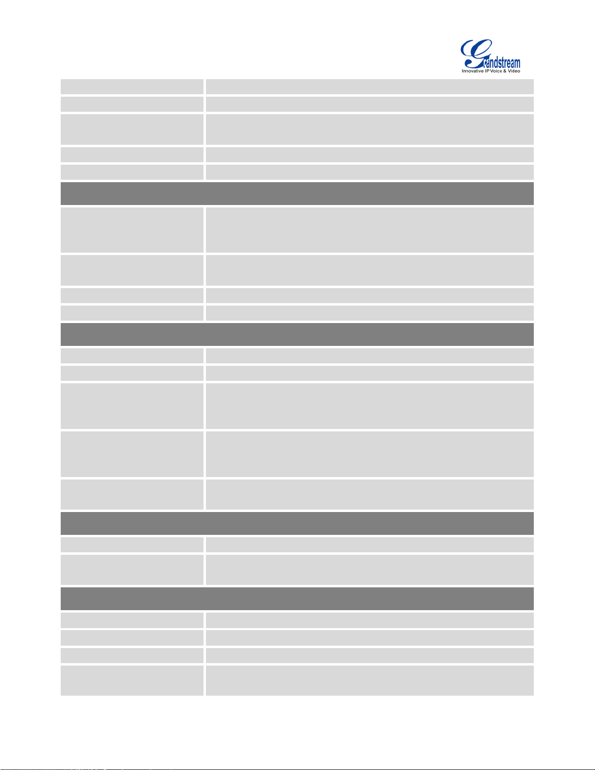
Firmware Version 1.0.2.5
UCM6510 IP PBX User Manual
Page 22 of 313
NAT Router
Power 1/2, PoE, USB, SD, T1/E1/J1, FXS 1/2, FXO 1/2, LAN, WAN,
LCD Display
length carrier
grade Line Echo Cancellation, Dynam ic Jit ter B uffer , Modem det e ct ion and
law, G.722, G.723.1 5.3K/6.3K, G.726, G.729A/B, iLBC,
provisioning of Grandstream
IP endpoints via ZeroConfig (DHCP Option 66/multicast SIP
TCP/UDP/IP, RTP/RTCP, ICMP, ARP, DNS, DDNS, DHCP, NTP, TFTP,
SSH, HTTP/HTTPS, PPPoE, SIP (RFC3261), STUN, SRTP, TLS, LDAP,
Call Progress Tone, Polarity Reversal, Hook Flash Timing, Loop Current
Media
Fail2ban, alert events, Whitelist, Blacklist, strong password based access
Dimensions
Yes (user configurable)
Peripheral Ports
LED Indicators
Reset Switch
Voice/Video Capabilities
Voice-over-Packet
Capabilities
Voice and Fax Codecs
Video Codecs
QoS
Signaling and Control
DTMF Methods
Digital Signaling
USB, SD
Cluster Heartbeat
128x32 dot matrix graphic LCD with DOWN and OK buttons
Yes, long press for factory reset and short press for reboot
LEC with NLP Packetized Voice Protocol Unit, 128ms-tail-
auto-switch to G.711
G.711 A-law/U-
GSM, AAL2-G.726-32, ADPCM; T .38
H.264, H.263, H.263+
Layer 3 QoS, Layer 2 QoS
In Audio, RFC2833, and SIP INFO
PRI, SS7, MFC/R2, E&M
Provisioning Protocol and
Plug-and-Play
Network Protocols
Disconnect Methods
Security
Advanced Defense
Physical
Universal Power Supply
Physical
TFTP/HTTP/HTTPS, auto-discovery & auto-
SUBSCRIBE/mDNS), eventlist between l ocal and remote trunks
HDLC, HDLC-ETH, PPP, Frame Relay
Disconnect, Busy Tone
SRTP, TLS, HTTPS, SSH
control
Input: 100-240VAC, 50-60Hz; Output: DC+12VDC, 1.5A
Unit Weight: 2.165 KG; Package weight: 3.012 KG
440mm (L) x 185mm (W) x 44mm (H)
Environmental
Operating: 32 - 113oF / 0 - 45oC, Humidity 10-90% (non-condensing)
Storage: 14 - 140oF / -10 - 60oC, Humidity 10-90% (non-condensing)

Firmware Version 1.0.2.5
UCM6510 IP PBX User Manual
Page 23 of 313
Mounting
English, Simplified Chinese, Traditional Chinese, Spanish, French,
Portuguese, German, Russian, Italian, Polish, Czech for web GUI;
German, Spanish, Greek, French, Italian, Dutch, Polish, Portuguese,
BT, NTT Japan
Multiple configurable call queues, automatic call distribution (ACD) based
TICK: AS/NZS CISPR 22 Class B, AS/NZS CISPR 24, AS/NZS
Additional Features
Rack mount and Desktop
Multi-language Support
Caller ID
Polarity Reversal/ Wink
Call Center
Customizable Auto Attendant
Maximum Call Capacity
Conference Bridges
Call Features
Compliance
Customizable IVR/voice prompts for English, Chinese, British English,
Russian, Swedish, Turkish, Hebrew and Arabic
Bellcore/Telcordia, ETSI-FSK, ETSI-DTMF, SIN 227 -
(pending)
Yes, with enable/disable option upon call establishment and termination
on agent skills/availability/busy level, in-queu e announcement
Up to 5 layers of IVR (Interactive Voice Response)
Up to 2000 registered SIP endpoints, up to 200 concurrent call s
Up to 8 bridges, up to 64 simultaneous conf erence attendees
Call park, call forward, call transfer, DND, DISA, ring group, pickup group,
blacklist, paging/intercom and etc
• FCC: Part 15 (CFR 47) Class B, Part 68
• CE: EN55022 Class B, EN55024, EN61000-3-2, EN61000-3-3,
EN60950-1, TBR21, RoHS
• A-
60950, AS/ ACIF S002
• ITU-T K.21 (Basic Level); UL 60950 (power adapter)
• T1: TIA-968-B Section 5.2.4
• E1: TBR12/TBR13, E1: AS/ACIF

Firmware Version 1.0.2.5
UCM6510 IP PBX User Manual
Page 24 of 313
This page intentionally left blank
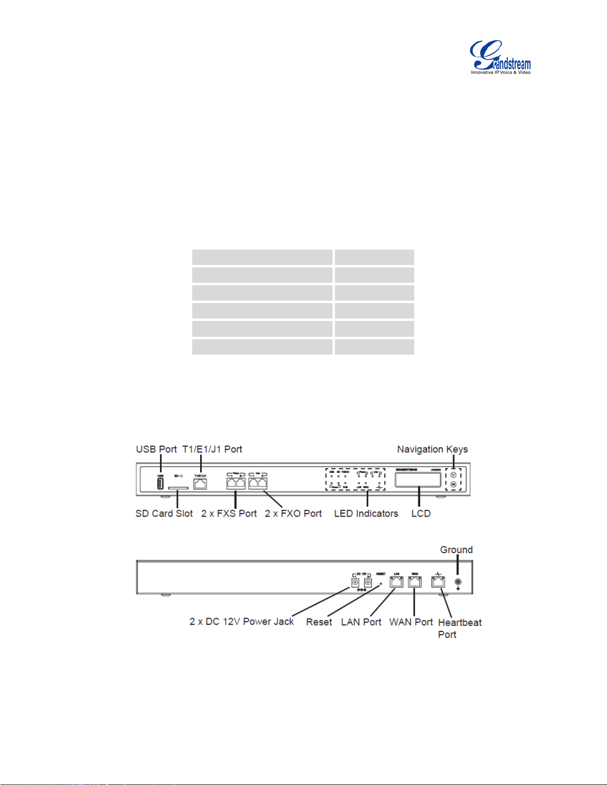
Firmware Version 1.0.2.5
UCM6510 IP PBX User Manual
Page 25 of 313
INSTALLATION
Main Case
Power Adapter
Ethernet Cable
Yes ( x 1)
Wall Mount
Screws
Quick Installation Gui de
Before deploying and configuring the UCM6510 series, the device needs to be properly powered up and
connected to network. This section describes detailed information on inst al l ation, connection and warranty
policy of the UCM6510 series.
EQUIPMENT PACKAGING
Table 2: UCM6510 Equipment Packaging
CONNECT YOUR UCM6510
CONNECT THE UCM6510
Figure 1: UCM6510 Front View
Yes ( x 1)
Yes ( x 2)
Yes ( x 2)
Yes ( x 6)
Yes ( x 1)
Follow the steps below to connect the UCM 6510 for initial setup:
Figure 2: UCM6510 Back View
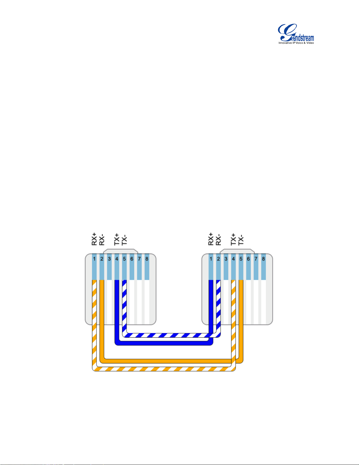
Firmware Version 1.0.2.5
UCM6510 IP PBX User Manual
Page 26 of 313
1. Connect one end of an RJ-45 Ethernet cable (cabl e type: straight through) into the WAN port of the
UCM6510; connect the other end into the uplink port of an Ethernet switch/hub.
2. Connect the 12V DC power adapter into the DC 12V power jack 1 on the ba c k of the UCM 65 10. Inse rt
the main plug of the power adapter into a surge-protected power outlet. (Connect the second power
adapter into the DC 12V power jack 2 for failover purpose in case the first one is down).
3. Wait for the UCM6510 to boot up. The LCD in the front will show its hardware information when the
bootup process is done.
4. Once the UCM6510 is successfully connected to the network, the LED indicator for the WAN port in
the front will be in solid green and the LCD show s up the IP address.
Depending on how the UCM6510 is used, users can follow the steps below for optional s etup:
1. PSTN Line Connection: connect PSTN lines from the wall jack to the UCM6510 LINE ports (FXO
ports).
2. Analog Line Connection: connect analog lines ( phone and fax) to the PHONE ports (FX S ports).
3. T1/E1/J1 Line Connection: connect one end of the T1/E1/J1 cable provided from the service provider
into the T1/E1/J1 port of the UCM6510; connect the other end into the T1/E1/J1 wall jack. T1/E1/J1
crossover cable should be used and it’s not provided in the UCM6510 package. Please see T1/E1/J1
crossover cable pin-out in the figure below:
Figure 3: UCM6510 T1/E1/J1 Crossover Cable Pin-out

Firmware Version 1.0.2.5
UCM6510 IP PBX User Manual
Page 27 of 313
SAFETY COMPLIANCES
The UCM6510 series IP PBX complies with FCC/CE and various safety standards. The UCM6510 power
adapter is compliant with the UL standard. Use the universal power adapter provided with the UCM6510
package only. The manufacturer’s warranty does not cover damages to the device caused by unsupport ed
power adapters.
WARRANTY
If the UCM6510 series IP PBX was purchased from a reseller, please contact the company where the
device was purchased for replacement, repair or refund. If the device was purchased directly from
Grandstream Networks, contact our Technical Support Team for a RMA (Return Materials Authorization)
number before the product is returned. Grandstream Networks reserves the right to remedy warranty
policy without prior notification.
--------------------------------------------------------------------------------------------------------------------------------------------
Warning:
Use the power adapter provided with th e UCM6510 se ries IP PBX. Do not use a dif ferent power ad apter as
this may damage the device. This t ype of damage is not covered under warranty.
--------------------------------------------------------------------------------------------------------------------------------------------

Firmware Version 1.0.2.5
UCM6510 IP PBX User Manual
Page 28 of 313
This page intentionally left blank

Firmware Version 1.0.2.5
UCM6510 IP PBX User Manual
Page 29 of 313
GETTING STA RT ED
The UCM6510 provides LCD interface, LED indication and web GUI configuration interface.
• The LCD displays hardware, software and network information. Users could also navigate in the LCD
menu for device information and basic network configuration.
• The LED indication at the front of the device provides interface connection and activity status.
• The web GUI gives users access to all the configurations and options for UCM6510 setup.
This section provides step-by-step instructions on how to use the LCD menu, LED indicators and w eb G UI
of the UCM6510. Once the basic settings are done, users could start making calls from UCM6510
extension registered on a SIP phone as described at the end of this section.
USE THE LCD MENU
• Default LCD Display
By default, when the device is powered up, the LCD will show device model (e.g., UCM6510),
hardware version (e.g., V1.4A) and IP address. Press "Down" button and the system time will be
displayed (e.g., 2014-10-21 14:20).
• Menu Access
Press "OK" button to start browsing menu options. Please see menu options in [Table 3: LCD Menu
Options].
• Menu Navigation
Press the "Down" arrow key to browser different menu options. Press the "OK" button to select an
entry.
• Exit
If "Back" option is available in the menu, select it to go back to the previous menu. For "Device Info"
"Network Info" and "Web Info" which do not have "Back" option, simply press the "OK" button to go
back to the previous menu. Additionally, the LCD will display default idle screen after staying in menu
option for 15 seconds.
• LCD Backlight
The LCD backlight will be on upon key pressing. The bac klight wil l go off after the LCD st ay s in idle f or
30 seconds.

Firmware Version 1.0.2.5
UCM6510 IP PBX User Manual
Page 30 of 313
The following table shows the LCD menu options.
tus for USB, SD,
T1/E1/J1, Phone 1/Phone 2, Line 1/Line 2 ports. After the LED test, select
Clock) test pattern. Check the sy stem t ime f rom LCD id le scre en by pre ssing
page. After
the test, reboot the device manually and the device will display the correct
Table 3: LCD Menu Options
View Events
Device Info
Network Info
Network Menu
• Critical Events
• Other Events
• Hardware: Hardware version number
• Software: Software version number
• P/N: Part number
• WAN MAC: WAN side MAC address
• LAN MAC: LAN side MAC address
• Uptime: System up time since the last reboot
• WAN Mode: DHCP, Static IP, or PPPoE
• WAN IP: IP address
• WAN Subnet Mask
• LAN IP: IP address
• LAN Subnet Mask
• WAN Mode: Select WAN mode as DHCP, Static IP or PPPoE
• Static Routes Reset: Click to reset the static route setting
• Reboot
• Factory Reset
• LCD Test Patterns
Press "OK" to start. Then p ress " Down" butt on to t e st different LCD patterns.
When done, press "OK" button to exit.
• Fan Mode
Select "Auto" or "On".
Factory Menu
• LED Test Patterns
Select "All On" "All Off" or "Blinking" and check LED sta
"Back" in the menu and the device will show the LED actual status again.
• RTC Test Patterns
Select "2022-02-22 22:22" or "2011-01-11 11:11" t o start the RTC ( Real-Time
"DOWN" button, or from web GUI->System Status->General

Firmware Version 1.0.2.5
UCM6510 IP PBX User Manual
Page 31 of 313
time.
st SVIP" to perform SVIP test on the device. This is mainly for
factory testing purpose which verifies the hardware connection inside the
• Hardware T e sting
Select "Te
device. The diagnostic result displays on the LCD after the test is done.
Web Info
• Protocol: Web access protocol. HTTP or HTTPS. By default it's HTTPS
• Port: Web access port nu m ber. By default it's 8089
• Enable SSH: Enable SSH access.
SSH Switch
• Disable SSH: Disable SSH access.
By default the SSH access is disabled.
USE THE LED INDICATORS
The UCM6510 has LED indicators in the front to display connection status. The following table shows the
status definitions.
Table 4: UCM6510 LED INDICATORS
LED Indicator LED Statu s
Power 1/Power 2
PoE
LAN
WAN
USB
SD
Solid: Connected
Fast Blinking: Data Transferring
Slow Blinking: Trying to connect
OFF: Not Connected
Phone 1 /Phone 2 (FXS)
Line 1/Line 2 FXO
Solid: Connected and working
Fast Blinking (0.5s on/0.5s off): No cable is
T1/E1/J1
connected; or connected but the link is not
working at all.
Slow Blinking (1s on/1s off): Connected but
the link is only working one-way

Firmware Version 1.0.2.5
UCM6510 IP PBX User Manual
Page 32 of 313
USE THE WEB GUI
ACCESS WEB GUI
The UCM6510 embedded Web server responds to HTTP/HTTPS GET/POST requests. Embedded HTML
pages allow users to configure the device through a Web browser such as Microsoft IE (version 8+),
Mozilla Firefox, Google Chrome and etc.
Figure 4: UCM6510 web GUI Login Page
To access the web GUI:
1. Connect the computer to the same network as t he UCM6510.
2. Ensure the device is properly powered up and sho ws its IP address on the LCD.
3. Open a web browser on the comput er and enter the IP address in t he address bar. The web login page
will display as shown above.
4. Enter the administrator’s login and password to access the web configuration menu. The default
administrator's username and password is "admin" and "admin". It is highly recommended to change
the default password after l ogi n for the first time.

Firmware Version 1.0.2.5
UCM6510 IP PBX User Manual
Page 33 of 313
--------------------------------------------------------------------------------------------------------------------------------------------
Note:
By default, the UCM6510 has "Redirect From Port 80" enabled. Therefore, if users ty pe in the UCM6510 IP
address in the web browser, the web page will be automatically redirected to the page using HTTPS and
port 8089.
For example, if the LCD shows 192.168.40.167, please enter 192.1 68.40.167 in your web browser and the
web page will be redirected to:
https://192.168.40.167:8089
The option "Redirect From Port 80" can be configured under the UCM6510 web GUI->Settings->HTTP
Server.
--------------------------------------------------------------------------------------------------------------------------------------------
WEB GUI CONFIGURATIONS
There are four main sections in the web GUI for users to view the PBX status, configure and manage the
PBX.
• Status: Displays PBX status, System Status, System Events and CDR.
• PBX: To configure extensions, trunks, call routes, zero config for auto provisioning, call features,
internal options, IAX settings, SIP settings, as well as ports confi guration for digital trunks.
• Settings: To configure network settings, firewall settings, change password, LDAP Server, HTTP
Server, Email Settings, Time Settings and NTP server.
• Maintenance: To perform firmware upgrade, backup configurations, cleaner setup, reset/reboot,
syslog setup and troubleshooting.
WEB GUI LANGUAGES
Currently the UCM6510 web GUI supports t he following languages:
English
Simplified Chinese
Traditional Chinese
Spanish

Firmware Version 1.0.2.5
UCM6510 IP PBX User Manual
Page 34 of 313
French
Portuguese
Russian
Italian
Polish
German
Users can select the displayed language in web GUI login page, or at the upper right of the web GUI after
logging in.
Figure 5: UCM6510 web GUI Language
SAVE AND APPLY CHANGES
Click on "Save" button after configuring the web GUI options in one page. After saving all the changes,
make sure click on "Apply Changes" button on the upper right of the web p age to submit all the changes. If
the change requires reboot to take effect, a prompted message will pop up for you to reboot the device.
Figure 6: UCM6510 web GUI: Apply Changes

Firmware Version 1.0.2.5
UCM6510 IP PBX User Manual
Page 35 of 313
MAKE YOUR FIRST CALL
Power up the UCM6510 and your SIP end point phone. Connect both devices to the network. Then follow
the steps below to make your first call.
1. Log in the UCM6510 web GUI, go to PBX->Basic/Call Routes->Extensions.
2. Click on "Create New SIP Extension" to create a new extension. You will need User ID, Password and
Voicemail Password information to register and use t he extension later.
3. Register the extension on your phone with the SI P User ID, SIP server and SIP Password information.
The SIP server address is the UCM6510 IP address.
4. When your phone is registered with the extension, dial *97 to access the voicemail box. Enter the
Voicemail Password once you hear "Password" voice prom pt.
5. Once successfully logged in to the voicemail , you will be prompted with the Voice Mail Main menu.
6. You are successfully connected to the PBX system now.

Firmware Version 1.0.2.5
UCM6510 IP PBX User Manual
Page 36 of 313
This page intentionally left blank

Firmware Version 1.0.2.5
UCM6510 IP PBX User Manual
Page 37 of 313
SYSTEM SETTINGS
This section explains configurations for system-wide parameters on the UCM6510. Those parameters
include Network Settings, Firewall, Change Password, LDAP server, HTTP server, Email settings, Time
Settings and NTP Server settings.
USER MANAGEMENT
User management is on web GUI->Settings->User Management page. User could create multiple
accounts for different administrators to log in the UCM6510 web GUI. Additionally the system will
automatically create user accounts along with creating new extensions for extension users to login to the
web UI using their extension number and password. All existing user accounts for web UI login will be
displayed on User Management pag e as shown in the following figure.
USER PRIVILEGES
Three privilege levels are supported:
• Super Admin
- This is the highest privilege. Super Admin can access all pages on UCM6510 web GUI, change
Figure 7: User Management Page Display

Firmware Version 1.0.2.5
UCM6510 IP PBX User Manual
Page 38 of 313
configuration for all options and execute all t he operations.
- Super Admin can create, edit and delete one or more users with “Admin” privilege
- Super Admin can edit and delete one or more users with “Consumer” privilege
- Super Admin can view operation logs generated by all users.
- By default, the user account “admin” is configured with “Super Admin” privilege and it’s the only
user with “Super Admin” privilege. The User Name and Privilege level cannot be changed or
deleted.
- Super Admin could change its own login password on web UI->Settings->Change Password
page.
- Super Admin could view operations done by all the users in web UI->Settings->User
Management->Operation Log.
• Admin
- Users with “Admin” privilege can only be created by “Super Admin” user.
- “Admin” privilege users are not allowed to ac cess the following pages:
Maintenance->Upgrade
Maintenance->Backup
Maintenance->Cleaner
Maintenance->Reset/Reboot
Settings->User Management->Operation Log
- “Admin” privilege users cannot create new users for login.
• Consumer
- A user account for web UI login is created automatically by the system when a new extension is
created.
- The user could log in the web UI with the extension number and password to access user
information, extension configuration and CDR of that extension.
CREATE NEW WEB UI USER
When logged in as Super Admin, click on
following dialog will prompt. Configure the parameters as shown in below table.
to create a new account for web UI user. The

Firmware Version 1.0.2.5
UCM6510 IP PBX User Manual
Page 39 of 313
Configure a username to identify the user which will be required in web UI login.
This is the role of the web UI user. Currently only “Admin” is supported when
First Name
Figure 8: Create New User
Table 5: User Management - Create New User
User Name
User Password
Privilege
Letters, digits and underscore are allowed in the user name.
Configure a password for this user which will be required in web UI login. Letters,
digits and underscore are allowed.
Super Admin creates a new user.
Department
Fax
Email Address
Enter the necessary information to keep a rec ord for this user.
Last Name
Home Number
Phone Number
Once created, the Super Admin can edit the users by clicking on
or delete the user by clicking on .
Figure 9: User Management – New Users

Firmware Version 1.0.2.5
UCM6510 IP PBX User Manual
Page 40 of 313
USER PORTAL
The user could log in web UI user portal using the extension number and password. When there is an
extension created in the UCM6510, the corresponding user account for the extension is automatically
created. The user portal allows limit ed access including user infor mation, exten sion configurat ion and CDR
information of the extension. The login username is the extension number and the password is configured
by Super Admin. The following figure shows the dialog of editing the account information by Super Admin.
The User Name must be the extension number and it’s not configurable.
Figure 10: Edit User Information by Super Admin
The following figure shows an example of login page using extension number 1000 as the username.
Figure 11: User Portal Login
After login, the web UI displays is shown as below.

Firmware Version 1.0.2.5
UCM6510 IP PBX User Manual
Page 41 of 313
Figure 12: User Portal Layout
For the configuration parameter information in each page, please refer [Table 5: User Management - Create
New User] for options in User Portal->Basic Information->User Information page; please refer to
[EXTENSIONS] for options in User Portal->Basic Information->Extension page; please refer to [CDR] for
User Portal->Basic Information->CDR page.
CONCURRENT MULTI-USER LOGIN
When there are multiple web UI users created, concurrent multi-user login is supported on the UCM6510.
Multiple users could edit options and have configurations take effect simultaneously. However, if different
users are editing the same option or making the same operation (by clicking on “Apply Changes”), a
prompt will pop up as shown in the following figure.
Figure 13: Multiple User Operation Error Prompt
OPERATION LOG
Super Admin has the authority to view operation logs on UCM6510 web GUI->Settings->User
Management->Operation Log page. Operation logs list operations done by all the web UI users, for
example, web UI login, creating trunk, creating outbound rule and etc. There are 6 columns to record the
operation details “Date”, “User Name”, “IP Address”, “Results”, “Page Operation” and “Specific Operation”.

Firmware Version 1.0.2.5
UCM6510 IP PBX User Manual
Page 42 of 313
The page where the operation is made. For example, login, logout, delete user,
Figure 14: Operation Logs
The operation log can be sorted and filtered for easy access. Click on the header of each column to sort.
For example, clicking on "Date" will sort the logs according to operation date and time. Clicking on "Date"
again will reverse the order.
Table 6: Operation Log Column Header
Date The date and time when the operation is executed.
User Name The username of the user who performed the operation.
IP Address The IP address from which the operati on is made.
Results The result of the operation.
Page Operation
Specific Ope ration
create trunk and etc.
Click on to view the options and values configured by this operation.
User could also filter the operation logs by time condition, IP address and/or username. Configure these
conditions and then click on
.

Firmware Version 1.0.2.5
UCM6510 IP PBX User Manual
Page 43 of 313
Figure 15: Operation Logs Filter
The above figure shows an example that operations made by user “support” on device with IP
192.168.40.173 from 2014-11-01 00:00 to 2014-11-06 15:38 are filtered out and displayed.
To delete operation logs, users can perform filtering first and then cli ck on
delete the filtered result of operation logs. Or users can click on
to delete all
to
operation logs at once.
CHANGE BINDING EMAIL
UCM6510 allows user to configure binding email in case login password is lost. UCM6510 login credential
will be sent to the designated email address. The feature can be found under web UI->Settings->User
Management->Change Binding Email.
Figure 16: Change Binding Email

Firmware Version 1.0.2.5
UCM6510 IP PBX User Manual
Page 44 of 313
Table 7: Change Binding Email option
Enter the password of
WAN port interface will be used for uplin k connection. LAN port interf ace will be
WAN port interface will be used for uplin k connection. LAN port interf ace will be
oth ports can be used for uplink connection. Users will need assign LAN 1 or
LAN 2 as the default interface in option "Default Interface" and configure
the account
Enter the current login user credential for UCM6510
Email Address Email Address is used to retrieve password when password is lost
NETWORK SETTINGS
After successfully connecting t he UCM6510 to the net work for the fi rst time, user s could log in the web G UI
and go to Settings->Network Settings to configure the network parameters for the device. Select each
tab in web GUI->Settings->Network Settings page to configure LAN/WAN settings, 802.1X and Port
Forwarding.
--------------------------------------------------------------------------------------------------------------------------------------------
Note:
To connect the UCM6510 to network, T1/E1/J1 data trunk can also be used, instead of using the
WAN/LAN port. Please see section [DATA TRUNK] to use UCM6510 data trunk to connect the device to
Internet.
--------------------------------------------------------------------------------------------------------------------------------------------
BASIC SETTINGS
Please refer to the following table s f or basic network configuration parameters on the UCM6510.
Table 8: UCM6510 Network Settings->Basic Settings
Select "Route", "Switch" or "Dual" mode on the network interface of UCM6510. The
default setting is "Route".
• Route
used to serve as router.
Method
• Switch
used as bridge for PC connection.
• Dual
B
"Gateway IP" for this interface if stat ic IP is used for the interface.
Preferred DNS Server Enter the preferred DNS server address. If Preferred DNS is configured, the

Firmware Version 1.0.2.5
UCM6510 IP PBX User Manual
Page 45 of 313
UCM6510 will use it as Primary DNS server.
The default setting is
Layer 2 QoS
Assign the VLAN tag of the layer 2 QoS p ackets for WAN port . The default value is
Allow IP Address From
Enter the DHCP IP Pool st art i ng address. The default setting is 192. 168.2.100.
LAN (when Method is set to "Switch")
default setting is
WAN (when "Method" is set to "Route")
IP Method Select DHCP, Static IP, or PPPoE. The default setting is DHCP.
IP Address Enter the IP address for static IP settings. The default setting is 192.168.0.160.
Subnet Mask
Enter the subnet mask address for static IP settings.
255.255.0.0.
Gateway IP Enter the gateway IP address for static IP settings. The default setting is 0.0.0.0.
DNS Server 1 Enter the DNS server 1 address for static IP settings. The default setting is 0.0.0.0.
DNS Server 2 Enter the DNS server 2 address for stati c IP settings.
User Name Enter the user name to connect via PPPoE.
Password Enter the password to connect via PPPoE.
802.1Q/VLAN Tag
Layer 2 QoS 802.1p
Priority Value
0.
Assign the priority value of the layer 2 QoS packet s for WAN port. The default value
is 0.
LAN (when Method is set to "Route")
IP Address Enter the IP address assigned to LAN port. The default setting is 192.168.2.1.
Subnet Mask Enter the subnet mask. The defaul t setting is 255.255.255.0.
DHCP Server Enable Enable or disable DHCP server cap abili t y. The default setting is "Yes".
DNS Server 1 Enter DNS server address 1. The default set ting is 8.8.8.8.
DNS Server 2 Enter DNS server address 2. The default set ting is 208.67.222.222.
Allow IP Address To Enter the DHCP IP Pool ending address. The default setting is 192.168.2. 254.
Default IP Lease Time Enter the IP lease time (in seconds). The default setting is 43200.
IP Method Select DHCP, Static IP, or PPPoE. The default setting is DHCP.
IP Address Enter the IP address for static IP settings. The default setting is 192.168.0.160.
Subnet Mask
Enter the subnet mask address for static IP settings. The
255.255.0.0.
Gateway IP Enter the gateway IP address for static IP settings. The default setting is 0.0.0.0.
DNS Server 1 Enter the DNS server 1 address for static IP settings. The default setting is 0.0.0.0.
DNS Server 2 Enter the DNS server 2 address for stati c I P settings.
User Name Enter the user name to connect via PPPoE.
Password Enter the password to connect via PP P oE.
Layer 2 QoS Assign the VLAN tag of the layer 2 QoS packets for LAN port. The default value is

Firmware Version 1.0.2.5
UCM6510 IP PBX User Manual
Page 46 of 313
802.1Q/VLAN Tag 0.
Assign the priority value of the layer 2 QoS packets for LAN port. The default value
LAN 1 / LAN 2 (when Method is set to "Dual")
LAN 1 (mapped to UCM6510 W AN po rt) or LA N 2 (m apped to U CM6510 LAN port )
and then configure network settings for LAN 1 and LAN 2. The default interface is
The default setting is
when the port is assigned as
User Name
Enter the user name to connect via PPPoE.
Assign the VLAN tag of the layer 2 QoS packets for LAN port. The default value is
Assign the priority value of the layer 2 QoS packets for LAN port. The default value
Layer 2 QoS 802.1p
Priority Value
is 0.
If "Dual" is selected as "Method", users will need assign the default interface to be
Default Interface
LAN 2.
IP Method Select DHCP, Static IP, or PPPoE. The default setting is DHCP.
IP Address Enter the IP address for static IP settings. The default setting is 192.168.0.160.
Subnet Mask
Gateway IP
Enter the subnet mask address for static IP settings.
255.255.0.0.
Enter the gateway IP address for static IP settings
default interface. The default setting is 0.0.0.0.
DNS Server 1 Enter the DNS server 1 address for static IP settings. The default setting is 0.0.0.0.
DNS Server 2 Enter the DNS server 2 address for stati c IP settings.
Password Enter the password to connect via PP P oE.
Layer 2 QoS
802.1Q/VLAN Tag
0.
Layer 2 QoS 802.1p
Priority Value
is 0.
• Method: Route
WAN port interface is used for uplink connection; LAN port interface is used as a router. Please see a
sample diagram below.

Firmware Version 1.0.2.5
UCM6510 IP PBX User Manual
Page 47 of 313
Figure 17: UCM6510 Network Interface Method: Route
• Method: Switch
WAN port interface is used for uplink connection; LAN port interface is used as bridge for PC
connection.

Firmware Version 1.0.2.5
UCM6510 IP PBX User Manual
Page 48 of 313
Figure 18: UCM6510 Network Interface Method: Switch
• Method: Dual
Both WAN port and LAN port are used for uplink connection. WAN port will be mapped to LAN 1
interface; LAN port will be mapped to LAN 2 interface. Users will need assign LAN 1 or LAN 2 as the
default interface in option "Default Interface" and configure "Gateway IP" if static IP is used for this
interface.

Firmware Version 1.0.2.5
UCM6510 IP PBX User Manual
Page 49 of 313
Figure 19: UCM6510 Network Interface Method: Dual
802.1X
IEEE 802.1X is an IEEE standard for port-based network access control. It provides an authentication
mechanism to device before the device is allowed to access Internet or other LAN resources. The
UCM6510 supports 802.1X as a supplicant/client to be authenticated. The following diagram and figure
show UCM6510 uses 802.1X mode “EAP-MD5” on WAN port as client i n the network to access Internet.
Figure 20: UCM6510 Using 802.1X as Client

Firmware Version 1.0.2.5
UCM6510 IP PBX User Manual
Page 50 of 313
Figure 21: UCM6510 Using 802.1X EAP-MD5
The following table shows the configuration parameters for 802.1X on UCM6510. Identity and MD5
password are required for authentication, which should be provided by the network administrator obtained
from the RADIUS server. If “EAP-TLS” or “EAP-PEAPv0/MSCHAPv2” is used as the 802.1X mode, users
will also need upload 802.1X CA Certificate and 802.1X Client Certificate, which should be also generated
from the RADIUS server.
Table 9: UCM6510 Network Settings->802.1X
Select 802.1X mode. The default setting is "Disable". The supported 802.1X mode
are:
802.1X Mode
• EAP-MD5
• EAP-TLS
• EAP-PEAPv0/MSCHAPv2
Identity Enter 802.1X mode identity information.
MD5 Password Enter 802.1X mode MD5 password info rmation.
802.1X CA Certificate Select 802.1X certificate from local PC and then upload.
802.1X Client
Certificate
Select 802.1X client certificate from local P C and then upload.
STATIC ROUTES
A static route is a pre-determined path that the network traffic travels to reach a specific host or network.
On the UCM6510, the static route function allow s the device to use manually configured rout es, rather than
dynamically assigned routes or default gateway configured in the UCM6510 web GUI->Network
Settings->Basic Settings to forward traffic. It can be used to define a route when no other routes is

Firmware Version 1.0.2.5
UCM6510 IP PBX User Manual
Page 51 of 313
available or necessary, or used in complementary with existing routing on the UCM6510 as a failover
192.168.66.0
Configure the subnet mask for the above destination address. If left blank, the
255.255.255.0
192.168.40.5
“Data Trunk 1”
backup, and etc.
• Click on
to create a new static route. The configuration parameters are listed
in the table below.
• Once added, users can select
• Select
to delete the static route.
to edit the static route.
• St atic routes configuration can be reset from LCD menu->Network Menu.
Table 10: UCM6510 Network Settings->Static Routes
Configure the destination IP addre ss or the destin ation I P subnet for the UCM6510
to reach using the static route.
Destination
Example:
IP address - 192.168.66.4
IP subnet -
default value is 255.255.255.255.
Netmask
Example:
Configure the gateway address so that t he UCM6510 can reach the dest ination via
this gateway. Gateway address is optional.
Gateway
Example:
Specify the network interface "LAN", "WAN" or “Data trunk 1” (
Interface
option will show only when the data trunk is enabled) on the UCM6510 to reach
the destination using the static route.
The following diagram shows a sample applicati on of static route usage on UCM6510.

Firmware Version 1.0.2.5
UCM6510 IP PBX User Manual
Page 52 of 313
Figure 22: UCM6510 Static Route Sample
The network topology of the above diagram is as below:
• Network 192.168.69.0 has IP phones registered to UCM6510 LAN 1 address
• Network 192.168.40.0 has IP phones registered to UCM6510 LAN 2 address
• Network 192.168.66.0 has IP phones registered to UCM6510 via VPN
• Network 192.168.40.0 has VPN connection established with network 192.168.66. 0
In this network, by default the IP phones in network 192.168.69.0 are unable to call IP phones in network
192.168.66.0 when registered on different interfaces on the UCM6510. Therefore, we need configure a
static route on the UCM6510 so that the phones in isolated networks can make calls between each other.
Figure 23: UCM6510 Static Route Configuration

Firmware Version 1.0.2.5
UCM6510 IP PBX User Manual
Page 53 of 313
PORT FORWORDING
. Up to 8 ports can be
When it is set to a range, WAN port and LAN port must be configured with the
the LAN port with the same port number, for
AN port must be configured with the
from WAN port will be forwarded to the LAN port with the same port number, for
Select protocol type "UDP Only", "TCP Only" or "TCP/UDP" for the forwarding in
The UCM6510 network interface supports router functions which provides users the ability to do port
forwarding. If the UCM6510 is set to "Route" under web GUI->Settings->Network Settings->Basic
Settings: Method, port forwarding is available for configuration.
The port forwarding configuration is under web GUI->Settings->Network Settings->Port Forwarding
page. Please see related settings in t he table below.
Table 11: UCM6510 Network Settings->Port Forwarding
Specify the WAN port number or a range of WAN ports
configured.
WAN Port
Note:
same range, such as WAN port: 1000-1005 and LAN port: 1000-1005, and access
from WAN port will be forwarded to
example, WAN port 1000 will be port forwarding to LAN port 1000.
LAN IP Specify the LA N I P address.
Specify the LA N port number or a range of LAN ports.
Note:
LAN Port
When it is set to a range, WAN port and L
same range, such as WAN port: 1000-1005 and LAN port: 1000-1005, and access
example, WAN port 1000 will be port forwarding to LAN port 1000.
Protocol T ype
the selected port. The default setting is "UDP Only".
The following figures demonstrate a port forwarding example to provide phone’s web UI access to public
side:
• The UCM6510 network mode is set to “Route”
• The UCM6510 WAN port is connected to uplink switch, with a public IP address configured, e.g.
1.1.1.1.
• The UCM6510 LAN port provides DHCP pool that connects to multiple phone devices in the LAN
network 192.168.2.x. The UCM6510 is used as a router, with gateway address 192.168.2.1
• There is a GXP2160 connected under the LAN interface network of the UCM6510. It obtains IP
address 192.168.2.100 from UCM6510 DHCP pool

Firmware Version 1.0.2.5
UCM6510 IP PBX User Manual
Page 54 of 313
• On the UCM6510 web UI->Settings->Network Settings->Port Forwarding, configure a port
forwarding entry as the figure shows below.
WAN Port: This is the port opened up on the WAN side for access purpose.
LAN IP: This is the GXP2160 IP address, under the LAN interface network of the UCM6510.
Protocol Type: We select TCP here for web UI access using HTTP.
Figure 24: UCM6510 Port Forwarding Configuration
This will allow users to access the GXP2160 web UI from public side, by typing in address “1.1.1.1:8088”.
Figure 25: GXP2160 Web Access Using UCM6510 Port Forwarding

Firmware Version 1.0.2.5
UCM6510 IP PBX User Manual
Page 55 of 313
DDNS SETTINGS
DDNS setting allows user to access UCM6510 via domai n name instead of IP address.
The UCM6510 supports DDNS service from the following DDNS provider:
• dydns.org
• noip.com
• freedns.afraid.org
• zoneedit.com
• oray.net
Here is an example of using noip.com for DDNS.
1. Register domain in DDNS service provider. Please note the UCM6510 needs to have public IP access.
Figure 26: Register Domain Name on noip.com
2. On web UI->Settings->Network Settings->DDNS Settings, enable DDNS service and configure
username, password and host name.
Figure 27: UCM6510 DDNS Setting

Firmware Version 1.0.2.5
UCM6510 IP PBX User Manual
Page 56 of 313
Port
Process
Type
389
Slapd
tcp/IPv4
3. Now you can use domain name instead of IP address to connect to the UCM6510 web UI.
Figure 28: Using Domain Name to Connect to UCM6510
FIREWALL
The UCM6510 provides users firewall configurations to prevent certain malicious attack to the UCM6510
system. Users could configure to allow, restrict or reject specific traffic through the device for security and
bandwidth purpose. The UCM6510 also provides Fail2ban feature for authentication errors in SIP
REGISTER, INVITE and SUBSCRIBE.
To configure firewall settings in UCM6510, go to web GUI->Settings->Firewall page.
STATIC DEFENSE
Under web GUI->Settings->Firewall->Static Defense page, users will see the following information:
• Current service information with port, proce ss and type.
• Typical firewall settings.
• Custom firewall settings.
The following table shows a sample cu rrent service status running on the UCM6510.
Table 12: UCM6510 Firewall->Static Defense->Current Service
7777 Asterisk tcp/IPv4
22 Dropbear tcp/IPv4

Firmware Version 1.0.2.5
UCM6510 IP PBX User Manual
Page 57 of 313
80 Lighthttpd tcp/IPv4
4569
Asterisk
udp/IPv4
If enabled, ICMP response will not be allowed for Ping request. The default
Death attack to the device. The default setting is
disabled. To enable or disable it, click on the check box for the LAN or WAN
8089 Lighthttpd tcp/IPv4
69 Opentftpd udp/IPv4
9090 Asterisk udp/IPv4
6060 zero_config udp/IPv4
5060 Asterisk udp/IPv4
5353 zero_config udp/IPv4
37435 Syslogd udp/IPv4
For typical firewall settings, users could configure the following options on the UCM6510.
Table 13: Typical Firewall Settings
Ping Defense
Enable
Ping-of-Death
Defense Enable
setting is disabled. To enable or disable it, click on the check box for the LAN or
WAN interface.
Enable to prevent Ping-of-
interface.
Under "Custom Firewall Settings", users could create new rules to accept, reject or drop certain traffic
going through the UCM6510. To create new rule, click on "Create New Rule" button and a new window will
pop up for users to specify rule options.
The following figure shows a firewall rule example that will deny SSH access for the UCM6510 from WAN
side.
Figure 29: Create New Firewall Rule

Firmware Version 1.0.2.5
UCM6510 IP PBX User Manual
Page 58 of 313
Rule Name
Specify the Fi rew al l rule name to identify the firewall rule.
Action
Select the traffic type.
"LAN", "WAN" or
If selected, users will need specify Sour ce (I P and port), Destination (IP and
Please note if the
Type
Service
Table 14: Firewall Rule Settings
Select the action for the Firewall to perform.
• ACCEPT
• REJECT
• DROP
• IN
If selected, users will need specify the network interface
"Both" for the incoming traffic.
• OUT
Select the service type.
• FTP
• SSH
• Telnet
• TFTP
• HTTP
• LDAP
• Custom
The new rule will be listed at the bottom of the page with sequence number, rule name, action, protocol,
type, source, destination and operation. Users can click on
the rule. Save the change and reboot the device for the configuration to take ef fect.
DYNAMIC DEFENSE
Dynamic defense can blacklist hosts dynamically when the UCM6510 is set to "Route" under web
GUI->Settings->Network Settings->Basic Settings: Method. If enabled, the traffic via TCP connection
coming into the UCM6510 can be monitored, which helps prevent massive connection attempts or brute
force attacks to the device. The blacklist can be created and updated by the UCM6510 firewall, which will
then be displayed in the web page. Please refer to the following table for dynamic defense options on the
UCM6510.
Dynamic Defense
Enable
port) and Protocol (TCP, UDP or Both) for the service.
source or the destination field is left blank, it will be used as "Anywhere".
to edit the rule, or click on to delete
Table 15: UCM6510 Firewall Dynamic Defense
Enable dynamic defense. The default setting is disabled.

Firmware Version 1.0.2.5
UCM6510 IP PBX User Manual
Page 59 of 313
Periodical Time
of TCP connections from a host exceeds the “Connection Threshold” within this
Configure the blacklist update time interval (in seconds). The default setting is
This defines how long the IP will be blocke d once added into th e UCM65 10
st. For example, if it’s set to 300 second s, the bloc ked IP add ress will only
be able to establish TCP connection with the UCM6510 again after 300
Once the number of connections from the
me host reaches the threshold during “Periodical Time Interval”, it will be
This is a list of IPs that will not be
Interval
Configure the dynamic defense periodi c time interval (in minutes). If the number
period, this host will be added into Bl acklist. The valid value is between 1 and 59
when dynamic defense is turned on. The default setting is 59.
Blacklist Update
Interval
120.
blackli
seconds.
Connection
Threshold
Configure the connection threshold.
sa
added into the blacklist. The default set ting is 100.
Configure the dynamic defense whitelist.
Dynamic Defense
Whitelist
blocked by the UCM6510. For example,
192.168.1.3
192.168.1.4
The following figure shows a configuration ex am pl e like this:
• If a host at IP address 192.168.40.7 initiates more than 20 TCP connections to the UCM6510 within 1
minute, it will be added into UCM6510 blacklist.
• This host 192.168.40.7 will be blocked by the UCM6510 for 300 seconds.
• Since IP address 192.168.40.5 is in whitelist , if the host at IP addre ss 192.168. 40.5 ini tiates more t han
20 TCP connections to the UCM6510 within 1 minute, it will not be added into UCM6510 blacklist. It
can still establish TCP connection with the UCM6510.
Figure 30: Configure Dynamic Defense

Firmware Version 1.0.2.5
UCM6510 IP PBX User Manual
Page 60 of 313
FAIL2BAN
Global Settings
Please make sure both "Enable
Fail2Ban" and "Asterisk Service" are turned on in order to use Fail2Ban for SIP
ceeds the max times of retry as
Configure the number of authentication failures durin g " Max Ret ry Durat ion" before
Configure IP address, CIDR mask or DNS host in the whiltelist. Fail2Ban will not
ban the host with matching address in this list. Up to 5 addresses can be added
Local Settings
. The default setting is disabled. Please make
sure both "Enable Fail2Ban" and "Asterisk Service" are turned on in order to use
Configure the number of authentication failures durin g " Max Ret ry Durat ion" before
the host is banned. The default setting is 10. Please make sure this option is
Fail2Ban feature on the UCM6510 provides intrusion detection and prevention for authentication errors in
SIP REGISTER, INVITE and SUBSCRIBE. Once the entry is detected within "Max Retry Duratio n", the
UCM6510 will take action to forbid the h ost for cert ain period a s defined in "Bann ed Durati on". This fe ature
helps prevent SIP brute force attacks to the PBX system.
Table 16: Fail2Ban Settings
Enable Fail2Ban. The default setting is disabled.
Enable Fail2Ban
authentication on the UCM6510.
Banned Duration
Max Retry Duration
MaxRetry
Fail2Ban Whitelist
Asterisk Service
Protocol
MaxRetry
Configure the duration (in seconds) for th e dete cted host t o be bann ed. The default
setting is 300. If set to -1, the host will be always banned.
Within this duration (in seconds), if a host ex
defined in "MaxRetry", the host will be banne d. The default setting is 5.
the host is banned. The default set ting is 10.
into the list.
Enable Asterisk service for Fail2Ban
Fail2Ban for SIP authentication on the UCM6510.
Configure the listening port number for the service. Currently only 5060 (for UDP)
is supported.
properly configured as it will override the "M axRetry" value under "Global Settings" .
CHANGE PASSWORD
After logging in the web GUI for the first time, it is highly recommended for users to change the default
password "admin" to a mor e compli cated p a ssword f or securit y pu rpose. F ollow t he steps below to change
the web GUI access password.
1. Go to web GUI->Settings->Change Password page.

Firmware Version 1.0.2.5
UCM6510 IP PBX User Manual
Page 61 of 313
2. Enter the old password first.
3. Enter the new password and retype the new password to confirm. The new password has to be at
least 4 characters. The maximum l ength of the password is 16 characters.
4. Click on "Save" and the user will be automatically logged out.
5. Once the web page comes back to the login page again, enter the username "admin" and the new
password to login.
LDAP SERVER
The UCM6510 has an embedded LDAP server for users to manage corporate phonebook in a centralized
manner.
• By default, the LDAP server has generated the first phonebook with PBX DN
"ou=pbx,dc=pbx,dc=com" based on the UCM6510 user extensions already.
• Users could add new phonebook with a different Phonebook DN for other external contacts. For
example, "ou=people,dc=pbx,dc=com".
• All the phonebooks in the UCM6510 LDAP server have the same Base DN "dc=pbx,dc=com".
• “cn” “ou” and “dc” are parts of LDAP data Interchange Format according to RFC 2849, which is how
the LDAP tree is filtered.
cn= Common Name
ou= Organization Unit
dc= Domain Component
• Here is an example of how the search for “ou=pbx,dc=pbx,dc=com” is performed in LDAP server
query.
From the dc=com Domain Component, find the dc=pbx Domain Component first. In the dc=pbx
Domain Component, find the Organizational Unit call ed pbx (ou=pbx) and then find the object that has
a Common Name of admin.
If users have the Grandstream phone provisioned by the UCM6510, the LDAP directory has been set up
on the phone and can be used right away for users t o access all phonebooks generated in the UCM6510.
Additionally, users could manually configure the LDAP client settings to manipulate the built-in LDAP
server on the UCM6510. If the UCM6510 has multiple LDAP phonebooks created, in the LDAP client
configuration, users could use "dc=pbx,dc=com" as Base DN to have access to all phonebooks on the
UCM6510 LDAP server, or use a specific phonebook DN, for example "ou=people,dc=pbx,dc=com", to
access to phonebook with Phonebook DN "ou=people,dc=pbx,dc=com " only.
To access LDAP Server settings, go to web GUI->Settings->LDAP Server.

Firmware Version 1.0.2.5
UCM6510 IP PBX User Manual
Page 62 of 313
LDAP SERVER CONFIGURATIONS
The following figure shows the default LDAP server configurations on the UCM6510.
Figure 31: LDAP Server Configurations
The UCM6510 LDAP server support s anony mous access ( read-only) by def ault. Theref ore the LDAP client
doesn't have to configure username and password to access the phonebook directory. The "Root DN" and
"Root Password" here are for LDAP management and configuration where users will need provide for
authentication purpose before modifying the LDAP information.
The default phonebook list in this LDAP server can be viewed and edited by clicking on
phonebook under LDAP Phonebook.
Figure 32: Default LDAP Phonebook DN
for the first

Firmware Version 1.0.2.5
UCM6510 IP PBX User Manual
Page 63 of 313
Figure 33: Default LDAP Phonebook Attributes
LDAP PHONEBOOK
Users could use the default phonebook, edit the default phonebook as well as add new phonebook on the
LDAP server. The first phonebook with default phonebook dn "ou=pbx,dc=pbx,dc=com" displayed on the
LDAP server page is for extensio ns in this PBX . Users cannot add o r delete con t act s di rectly. The contacts
information will need to be modified via web GUI->PBX->Basic/Call Routes->Extensions first. The
default LDAP phonebook will then be updated automatically.
• Add new phonebook
A new sibling phonebook of the default PBX phonebook can be added by clicking on "Add" under
"LDAP Phonebook" section.
Figure 34: Add LDAP Phonebook

Firmware Version 1.0.2.5
UCM6510 IP PBX User Manual
Page 64 of 313
Configure the "Phonebook Prefix" first. The "Phonebook DN" will be automatically filled in. For
example, if configuring "Phonebook Prefix" as "people", the "Phonebook DN" will be filled with
"ou=people,dc=pbx,dc=com".
Once added, users can select
or select
to delete the phonebook.
to edit the phonebook attributes and c ontact list (see figure below),
Figure 35: Edit LDAP Phonebook
• Import phonebook from your computer to LDAP server
Click on “Import Phonebook” and a dialog will pro m pt as shown in the figure below.
Figure 36: Import Phonebook

Firmware Version 1.0.2.5
UCM6510 IP PBX User Manual
Page 65 of 313
The file to be imported must be a CSV file with UTF-8 encoding. Users can open the CSV file with
Notepad and save it with UTF-8 encoding.
Here is how a sample file looks like. Please note “Account Number” and “Phonebook DN” fields are
required. Users could export a phonebook file from the UCM6510 LDAP phonebook section first and
use it as a sample to start with.
Figure 37: Phonebook CSV File Format
The Phonebook DN field is the same “Phonebook Pr efix” entry as when the user clicks on “Add” to
create a new phonebook. Therefore, i f the user enters “phonebook” in “Phonebook DN” field in the
CSV file, the actual phonebook DN “ou=phonebook,dc=pbx,dc=com” will be automatically c reated by
the UCM6510 once the CSV file is imported.
In the CSV file, users can specify dif ferent phonebook DN field s for dif ferent cont act s. If the phonebook
DN already exists on the UCM6510 LDAP Phonebook, the conta cts in the CSV file will be added into
the existing phonebook. If the phone book D N doe sn’t ex ist on the U CM6510 LDA P Phonebook, a new
phonebook with this phonebook DN will be cr eated.
The sample phonebook CSV file in above picture will result in the following LDAP phone book in the
UCM6510.
As the default LDAP phonebook wit h DN “ou=pbx,dc=pbx,dc=com” cannot be edit ed or deleted in
LDAP phonebook section, use rs cannot import cont act s wi th Phone book DN field “pbx” if ex isted in t he
Figure 38: LDAP Phonebook After Import

Firmware Version 1.0.2.5
UCM6510 IP PBX User Manual
Page 66 of 313
CSV file.
• Export phonebook to your computer from UCM6510 LDAP server
Select the checkbox for the LDAP phonebook and then click on “Export Selected Phonebook” to
export the selected phonebook. The exported phonebook can be used as a record or a sample CSV
file for the users to add more contacts in it and import to the UCM6510 again.
Figure 39: Export Selected LDAP Phonebook
LDAP CLIENT CONFIGURATIONS
The configuration on LDAP client is similar when you use other LDAP servers. Here we provide an
example on how to configure the LDAP client on the SIP end points to use the default PBX phonebook.
Assuming the server base dn is "dc=pbx,dc=com", configure the LDAP clients as follows (case
insensitive):
Base DN: dc=pbx,dc=com
Login DN: Please leave this field empty
Password: Please leave this field empty
Anonymous: Please enable this option
Filter: (|(CallerIDName=%)(AccountNumber=%))
Port: 389
The following figure gives a sample configurat i ons for UCM6510 acting as a LDAP client.

Firmware Version 1.0.2.5
UCM6510 IP PBX User Manual
Page 67 of 313
Figure 40: LDAP Client Configurations
To configure Grandstream IP phones as the LDAP client, please refer to the following example:
Server Address: The IP address or domain name of the UCM6510
Base DN: dc=pbx,dc=com
User Name: Please leave this field empty
Password: Please leave this field empty
LDAP Name Attrib ute: Ca ll erIDNam e Em ail Department FirstName LastName
LDAP Number Attribute: AccountNumber MobileNumber HomeNumber Fax
LDAP Number Filter: (AccountNumber=%)
LDAP Name Filter: (CallerI DNam e =%)
LDAP Display Nam e : AccountNumber CallerIDName
LDAP Version: If existed, please selec t LDAP Version 3
Port: 389
The following figure shows the configuration information on a Grandstream GXP2200 to successfully use
the LDAP server as configured in [Figure 31: LDAP Server Configurations].

Firmware Version 1.0.2.5
UCM6510 IP PBX User Manual
Page 68 of 313
HTTP SERVER
The UCM6510 embedded web server responds to HTTP/HTTPS GET/POST requests. Embedded HTML
pages allow the users to configure the PBX through a web browser such as Microsoft IE, Mozilla Firefox
and Google Chrome. By default, the PBX can be accessed directly by typing IP address in the PC's web
browser (e.g., 192.168.40.50). It will then be automatically redirected to HTTPS using Port 8089 (e.g.,
https://192.168.40.50:8089). Users could also change the access protocol and port as preferred under
web GUI->Settings->HTTP Server.
Figure 41: GXP2200 LDAP Phonebook Configuration

Firmware Version 1.0.2.5
UCM6510 IP PBX User Manual
Page 69 of 313
Table 17: HTTP Server Settings
Enable or disable redirect from port 80. On the PBX, the default access
enabled, the access using HTTP with Port 80 will be redirected to HTTPS
. The
This also defines whether to use HTTP or
HTTPS to download the config file in zero config as the UCM6510 is
served as HTTP/HTTPS server that has the device config files for zero
tting your Email to other
MTA: Mail Transfer Agent. The Email will be sent from the configured
domain. When MTA is selected, there is no need to set up SMTP
r, the Emails sent from
Client: Submit Emails to the SMTP server. A SMTP server is required
Specify the SMTP server when using type "Client". For example, if using
Username is required when using type "Client". Normally it's the Email
Password to log in for the above Username (Email address) is required
Redirect From Port 80
protocol is HTTPS and the default port number is 8089. When t his opti on is
with Port 8089. The default setti ng i s " Enable".
Select HTTP or HTTPS as the protocol to access the HTTP server
default setting is "HTTPS".
Protocol T ype
config.
Port
Specify port number t o access t he HTTP se rver. The default port number is
8089.
Once the change is saved, the web page will be redirected t o t he login page using the new URL. Enter the
username and password to login again.
EMAIL SETTINGS
The Email application on the UCM6510 can be used to send out alert event Emails, Fax (Fax-To-Email),
Voicemail (Voicemail-To-Email) and etc. The configuration parameters can be accessed via web
GUI->Settings->Email Settings.
Table 18: Email Settings
TLS Enable
Enable or disable TLS during transferring/submi
SMTP server. The default setting is "Yes".
•
Type
server for it or no user login is req uir ed. Ho weve
MTA mi ght be considered as spam by the target SMTP server.
•
and users need login with correct credentials.
Domain Specify the domai n name to be used in the Email when using type "MTA".
Server
Username
Password
Display Name Specify the display name in the FROM header in the Email.
Gmail as the SMTP server, you can configure it as smtp.gmail.com:465.
address.
when using type "Client".

Firmware Version 1.0.2.5
UCM6510 IP PBX User Manual
Page 70 of 313
Sender
Specify the s ender's Email address.
For example, pbx@example.mycompany.com.
The following figure shows a sample Email settings on the UCM6510, assuming the Email is using
smtp.gmail.com as the SMTP serv er and the port number is 465.
Figure 42: UCM6510 Email Settings
Once the configuration is finished, click on "Save" first. Then click on "Test" button to make sure the Email
setting is working.
The following figure shows the new dialog prompted to test the Email setting. Fill in a valid Email address
to send a test Email to verify the Email settings on t he UCM6510.
Figure 43: UCM6510 Email Settings: Send Test Email

Firmware Version 1.0.2.5
UCM6510 IP PBX User Manual
Page 71 of 313
TIME SETTINGS
Specify the URL or IP address of the NTP server for the UCM6510 to
. The default NTP server is
get provisioned for Time Zone
from DHCP Option 2 in the local serv er aut omatically. The default setting is
is allowed to get provisioned for NTP Server
ver automatically. This will override
can display correct
ify the time zone
AUTO TIME UPDATING
The current system time on the UCM6510 is displayed on the upper right of the web page. It can also be
found under web GUI->Status->System Status->General.
To configure the UCM6510 to update time automatically, go to web GUI->Settings->Time Settings->
Auto Time Updating.
--------------------------------------------------------------------------------------------------------------------------------------------
Note:
The configurations under Web GUI->Settings->Time Settings->Time Auto Updating page require
reboot to take effect. Please consider configuring auto time updating related changes when setting up the
UCM6510 for the first time to avoid service interrupt after installation and deployment in production.
--------------------------------------------------------------------------------------------------------------------------------------------
Table 19: Auto Time Updating
Remote NTP Server
Enable DHCP Option 2
Enable DHCP Option 42
Time Zone
synchronize the date and time
ntp.ipvideotalk.com.
If set to "Yes ", the UCM6510 is allowed to
"Yes".
If set to "Yes ", the UCM6510
from DHCP Option 42 in the local ser
the manually configured NTP Server. The default setting is "Yes".
Select the proper time zone option so the UCM6510
time accordingly.
If "Self-Defined Tome Zone" is selected, please spec
parameters in "Self-Defined Time Zone" field as d escribed in below option.

Firmware Version 1.0.2.5
UCM6510 IP PBX User Manual
Page 72 of 313
Self-Defined Time Zone
Defined Time Zone" is selected in "Time Zone" option, users will
This indicates a time zone with 6 hours offset and 1 hour ahead for DST,
the Prime Meridian (A.K.A: International or Greenwich Meridian); If it is
3rd Tuesday…). Norm al ly 1, 2, 3, 4 are used. If 5 is used, it means the l ast
If "Selfneed define their own time zone following the f ormat below.
The syntax is: std offset dst [offset], start [/time], end [/time]
Default is set to: MTZ+6MDT+5,M4.1.0,M 11.1.0
MTZ+6MDT+5
which is U.S central time. If it is positive (+), the local time zone is west of
negative (-), the local time zone is east.
M4.1.0,M11.1.0
The 1st number indicates Month: 1, 2, 3..., 12 (for Jan, Feb...Dec.).
The 2nd number indicates the nth iteration of t he weekday: (1st Sunday,
iteration of the weekday.
The 3rd number indicates weekday: 0, 1, 2…6 (for Sun, Mon, Tues... Sat).
Therefore, this example is the DST which starts from the First S unday of
April to the 1st Sunday of November.
SET TIME M A N UA LLY
To manually set the time on the UCM6510, go to Web GUI->Settings->Time Settings->Set Time
Manually. The format is YYYY-MM-DD HH:MI:SS.
Figure 44: Set Time Manually

Firmware Version 1.0.2.5
UCM6510 IP PBX User Manual
Page 73 of 313
--------------------------------------------------------------------------------------------------------------------------------------------
Note:
Manually setup time will take effect immediately after saving and applying change in the web UI. If users
would like to reboot the UCM6510 and keep the manually setup time setting, please make sure "Remote
NTP Server", "Enable DHCP Option 2" and "Enable DHCP Option 42" options under Web
GUI->Settings->Time Settings->Time Au to Updating page are unchecked or set to empty. Otherwise,
time auto updating settings in this pag e wil l take effect af ter reboot.
--------------------------------------------------------------------------------------------------------------------------------------------
OFFICE TIME
On the UCM6510, the system administrator can define "office time", which can be used to configure time
condition for extension call forwarding schedule and inbound rule schedule. To configure office time, go to
Web GUI->Settings->Time Settings->Office Time. Click on "Create New Office Time" to create an office
time.
Figure 45: Create New Office Time

Firmware Version 1.0.2.5
UCM6510 IP PBX User Manual
Page 74 of 313
Table 20: Create New Office Time
Start Time
Configure the start time for office hour .
Check this options to show advanced options. Once selected, please
Month
Select the months for office time.
End Time Configure the end time for office hou r
Week Select the work days in one week.
Show Advanced Options
specify "Month" and "Day" below.
Day Select the work days in one month.
Select "Start Time", "End Time" and the day for the "Week" for the office time. The system administrator
can also define month and day of the month as advanced options. Once done, click on "Save" and then
"Apply Change" for the office time t o take effect. The office time will be listed in the web page as the figure
shows below .
Figure 46: Settings->Time Settings->Office Time
• Click on to edit the office time.
• Click on
to delete the office time.
• Click on "Delete Selected Office Times" to delete multiple selected office ti m es at once.
HOLIDAY
On the UCM6510, the system administrator can define "holiday", which can be used to configure time
condition for extension call forwarding schedule and inbound rule schedule. To configure holiday, go to
Web GUI->Settings->Time Settings->Holiday. Click on "Create New Holiday" to create holiday time.

Firmware Version 1.0.2.5
UCM6510 IP PBX User Manual
Page 75 of 313
Figure 47: Create New Holiday
Name
Specify the holi day name to identify this holiday.
d options. If selected, please specify
Table 21: Create New Holiday
Holiday Memo Create a note for the holiday.
Month Select the month for the holiday.
Day Select the day for the holiday.
Show Advanced Options
Check this option to show advance
the days as holiday in one week below.
Week Select the days as holiday in one week.
Enter holiday "Name" and "Holiday Memo" for the new holiday. Then select "Month" and "Day". The
system administrator can also define days in one week as advanced options. Once done, click on "Save"
and then "Apply Change" for the holiday to take effect. The holiday will be listed in the web page as the
figure shows below.

Firmware Version 1.0.2.5
UCM6510 IP PBX User Manual
Page 76 of 313
Figure 48: Settings->Time Settings->Holiday
• Click on to edit the holiday.
• Click on
to delete the holiday.
• Click on "Delete Selected Holidays" to delete multiple selected holidays at once.
--------------------------------------------------------------------------------------------------------------------------------------------
Note:
For more details on how to use office time and holiday, please refer to the link below:
http://www.grandstream.com/products/ucm_series/ucm61xx/documents/how_to_use_office_time_and_hol
iday_ucm6100.pdf
--------------------------------------------------------------------------------------------------------------------------------------------
NTP SERVER
The UCM6510 can be used as a NTP server for the NTP clients to synchronize their time with. To
configure the UCM6510 as the NTP server, set "Enable NTP server" to "Yes" under web
GUI->Settings->Time Settings->NTP Server. On the client side, point the NTP server address to the
UCM6510 IP address or host name t o use the UCM6510 as the NTP serve r.

Firmware Version 1.0.2.5
UCM6510 IP PBX User Manual
Page 77 of 313
RECORDINGS STORAGE
The UCM6510 supports call recordings automatically or manually and the recording files can be saved in
external storage plugged in the UCM6510 or on the UCM6510 locally. To manage the recording storage,
users can go to UCM6510 w eb GUI->Settings->Recordings Storage page and select whether to store
the recording files in USB Disk, SD card or locally on the UCM6510.
• If “Enable Auto Change” is selected, the recording files will be automatically saved in the available
USB Disk or SD card plugged into the UCM6510. If both USB Disk and SD card are plugged in, the
recording files will be always saved in the USB Disk.
• If “Local” is selected, the recordings will be stored i n UCM6510 internal storage.
Figure 49: Settings->Recordings Storage

Firmware Version 1.0.2.5
UCM6510 IP PBX User Manual
Page 78 of 313
• If “USB Disk” or “SD Card” is selected, the recordings will be stored in the corresponding plugged in
external storage device. Please note the options “USB Disk” and “SD Card” will be displayed only if
they are plugged into the UCM6510.
Once “USB Disk” or “SD Card” is selected, click on “OK”. The user will be prompted to confirm to copy
the local files to the external storage device.
Figure 50: Recordings Storage Prompt Information
Click on “OK” to continue. The users will be prompted a new dialog t o select the cat egories for the fi les
to be copied over.
On the UCM6510, recording files are generated and exist in 3 categories: normal call recording files,
conference recording files, and call queue recording files. Therefore users have the following options
when select the categories to copy the files to the external device:
- Recording Files: Copy the normal recording f il es to the external device.
- Conference: Copy the conference recording files to the external device.
- Queue: Copy the call queue recording files t o the external device.
Figure 51: Recording Storage Category

Firmware Version 1.0.2.5
UCM6510 IP PBX User Manual
Page 79 of 313
- All: Copy all recording files to the external device.
LOGIN TIMEOUT SETTINGS
After the user logs in the UCM6510 web UI, the user will be automatically logged out after certain timeout.
This timeout value can be specified under UCM6510 web GUI->Settings->Login T imeout Setting s page.
The “User Login T imeo ut” v alue is in m inute and t he def ault set tin g is 10 m inutes. If the user doesn’t make
any operation on web UI within the timeout, the user w ill be logged o ut automat ically. After that , the web UI
will be redirected to the login page and the user will need to enter username and pa ss word to log in.
If set to 0, there is no timeout for the web UI login sessi on and the user will not be automat ically logged out .
Figure 52: Login Timeout Settings

Firmware Version 1.0.2.5
UCM6510 IP PBX User Manual
Page 80 of 313
This page intentionally left blank

Firmware Version 1.0.2.5
UCM6510 IP PBX User Manual
Page 81 of 313
PROVISIONING
OVERVIEW
Grandstream SIP Devices can be configured via Web interface as well as via configuration file through
TFTP/HTTP/HTTPS download. All Grandstream SIP devices support a proprietary binary format
configuration file and XML f ormat config uration fil e. The UCM65 10 provide s a Plug and Play mechani sm to
auto-provision the Grandstream SIP devices in a zero configuration manner by generating XML config file
and having the phone to download it within LAN area. This allows users to finish the installation with ease
and start using the SIP devices in a managed way.
To provision a phone, three steps are involved, i.e., discovery, configuration and provisioning. This section
explains how Zero Config works on the UCM6510. The settings for this feature can be accessed via Web
UI->PBX->Zero Config.
CONFIGURATION ARCHITECTURE FOR END POINT DEVICE
The end point device configurati on in Zero Config is divided i nto the f ollowing three layers with priority f rom
the lowest to the highest:
• Global
This is the lowest layer. Users can configure the most basic options that could apply to all Grandstream
SIP devices during provisioning via Zero Config.
• Model
In this layer, users can define model-specific options for the co nfiguration template.
• Device
This is the highest layer. Users can configure device-specific options for the configuration for individual
device here.
Each layer also has its own structu re in different levels. Please see figure below. The details for each layer
are explained in sections [GLOBAL CONFIGURATION], [MODEL CONFIGURATION] and [DEVICE
CONFIGURATION].

Firmware Version 1.0.2.5
UCM6510 IP PBX User Manual
Page 82 of 313
Figure 53: Zero Config Configuration Architecture for End Point Device
The configuration in model layer and device layer have all the options in global layers already, i.e., the
options in global layer is a subset of the options in model layer and device layer. If an option is set in all
three layers with different values, the highest layer value will override the value in lower layer. For
example, if the user selects English for Language setting in Global Policy and Spanish for Language
setting in Default Model Template, the language setting on the device to be provisioned will use S p anish as
model layer has higher priority than global layer. To sum up, configurations in higher layer will always
override the configurations for the same options/fields in the lower layer when presented at the
same time.
After understanding t he Zero Config configuration architecture, users could configure the avail able options
for end point devices to be provisioned by the UCM6510 by going through the three layers. This
configuration architecture allows users to set up and manage the Grandstream end point devices in the
same LAN area in a centralized way.
AUTO PROVISIONING SETTINGS
By default, the Zero Config feature is enabled on the UCM6510 for auto provisioning. Two methods of
auto provisioning are used.

Firmware Version 1.0.2.5
UCM6510 IP PBX User Manual
Page 83 of 313
Figure 54: UCM6510 Zero Config
• SIP SUBSCRIBE
When the phone boots up, it sends out SUBSCRIBE to a multicast IP address in the LAN. The
UCM6510 discovers it and then sends a NOTIFY with the XML config file URL in the message body.
The phone will then use the path to download the config file generated in the UCM6510 and take the
new configuration.
• DHCP OPTION 66
This method should be used only when the UCM6510 is set to "Route" mode under web
GUI->Settings->Network Settings->Basic Settings: Method. When the phone restarts (by default
DHCP Option 66 is turned on), it will send out a DHCP DISCOVER request. The UCM6510 receives it
and returns DHCP OFFER with the config server path URL in the Option 66, for example,
https://192.168.2.1:8089/zccgi/. The pho ne will then use the path to download the config fi le generated
in the UCM6510.
To start the auto provisioning process, under Web GUI->PBX->Zero Config->Zero Config Settings, fill in
the auto provision information.

Firmware Version 1.0.2.5
UCM6510 IP PBX User Manual
Page 84 of 313
Figure 55: Auto Provision Settings
By default, this is disabled. If disabled, when SIP device boots up, the
send the configuration path to the device when you
have any manual configuration on the device. This manual configuration
NOTIFY from the UCM6510 which will include the XML config file URL for
If enabled, when the device is discovered, the PBX will automatically
e range defined in "Zero Config Extension
Table 22: Auto Provision Settings
Enable Zero Config
Enable or disable the Zero Config feature on the PBX. The default setting
is enabled.
UCM6510 will only
includes:
- Any configuration under BASIC and CUSTOM page of the device
Enable Automatic
Configuration Assignment
in Zero Config page
- If any global or model template (expect for the defaul t template) is
selected for the assigned device in Zero Config page.
Note:
When disabled, SIP devices can still be provisioned by manually sending
the SIP device to download.
Automatically Assign Extension
assign an extension within th
Segment" to the device. The default setting is disabled.
Zero Config Extension
Segment
Click on the link "Zero Config Extension Segment" to specif y the ex tension
range to be assigned if "Automatically Assign Extension" is enabled. The
default range is 5000-6299. Zero Config Extension Segment range can b e

Firmware Version 1.0.2.5
UCM6510 IP PBX User Manual
Page 85 of 313
Enable Pick Extension
list will be sent out to the device after receiving
the device's request. This feature is for the GXP series phones that
support selecting extension to be provisioned via phone's LCD. The
Click on the link "Pick Extension Segment" to specify the extension list to
>Extension Preference section: "Pick
Specify the number of minutes to allow the phones being provisioned to
Pick Extension Segment
defined in web UI->PBX->Internal Options->General page->Extension
Preference section: "Auto Provision Extensions".
If enabled, the extension
default setting is disabled.
be sent to the device. The default range is 4000 to 4999. Pick Extension
Segment range can be defined in web UI->PBX->Internal
Options->General page-
Extensions".
Pick Extension Period (hour):
pick extensions.
Please make sure an extension is manually assigned to the phone or "Automatically Assign Extension" is
enabled during provisioning. Aft er the configuration on the UCM6510 web GUI, click on "Save" and "Apply
Changes". Once the phone boots up and picks up the config file from the UCM6510, it will take the
configuration right away.
DISCOVERY
Users could manually discover the device by specifying the IP address or scanning the entire LAN
network. Three methods are supported to scan the devices.
• PING
• ARP
• SIP Message (NOTIFY)
Click on "Auto Discover" under web GUI-> PBX-> Zero Config-> Zero Config, fill in the "Scan Method"
and "Scan IP". The IP address segment will be automatically filled in based on the network mask detected
on the UCM6510. If users need scan the entire n etwork se gment, ent er 255 (for example, 19 2.168.40.2 55)
instead of a specific IP address. Then click on "Save" to start discovering the devices within the same
network. To successfully discover the devices, "Zero Config" needs to be enabled on the UCM6510 web
GUI->PBX->Zero Config->Auto Provisioning Settings.

Firmware Version 1.0.2.5
UCM6510 IP PBX User Manual
Page 86 of 313
Figure 56: Auto Discover
The following figure shows a list of discovered phones. The MAC address, IP Address, Extension (if
assigned), Version, Vendor, Model, Connection Status, Create Config, Options (Edit/Delete/Update) are
displayed in the list.
Figure 57: Discovered Devices
GLOBAL CONFIGURATION
GLOBAL POLICY
Global configuration will apply to all the connected Grandstream SIP end point devices in the same LAN
with the UCM6510 no matter what the Grandst ream device model it is. It is divided into two levels:
• Web UI->PBX->Zero Config->Global Policy
• Web UI->PBX->Zero Config->Global Templates.
• Global Templates configuration has higher priority to Global Policy configuration.
Global Policy can be accessed in web GUI->PBX->Zero Config->Global Policy page. On the top of the
configuration table, users can select category in the "Options" dropdown list to quickly navigate to the
category. The categories are:
• Localization: configure display language, data and time.
• Phone Settings: configure dial plan, call features, NAT, call progress tones and etc.

Firmware Version 1.0.2.5
UCM6510 IP PBX User Manual
Page 87 of 313
• Contact List: configure LDAP and XML phoneboo k download.
Date and Time
Configure the time display in 12-hour or 24-hour format on the SIP end
Configure the URL or IP address of the NTP server. The SIP end device
• Maintenance: configure upgrading, web access, Telnet/SSH access and syslog.
• Network Settings: configure IP address, QoS and STUN settings.
• Customization: customize LCD screen wallpaper for the supported models.
Figure 58: Global Policy Categories
Select the checkbox on the left of the parameter you would like to configure to active the dropdown list for
this parameter.
The following tables list the Global Pol icy configuration parameters for t he SIP end device.
Table 23: Global Policy Parameters - Localization
Language settings
Language Select the LCD display language on the SIP end device.
Date Format Configure the date display format on the SI P end device’s LCD.
Time Format
NTP Server
device’s LCD.
may obtain the date and time from the s erv er.
Time Zone Configure the time zone used on the SIP end device.

Firmware Version 1.0.2.5
UCM6510 IP PBX User Manual
Page 88 of 313
Default Call Settings
When enabled, “Do Not Disturb”, “Call Forward” and other call features
If set to “Yes”, pressing the number key “#” will immediately dial out the
Configure call progress tones including ring tone, dial tone, second dial
Please refer to user manual of the SIP devices to be provisioned for
Select “Default Mode” or “Toggle Headset/Speaker” for the Headset key.
If "Manual" is selected, the LDAP configuration below will be applied
in from UCM6510
Table 24: Global Policy Parameters - Phone Settings
Dial Plan
Enable Call Features
Configure the default dial plan rule. For synt ax and exam ples, plea se refer
to user manual of the SIP devices to be provisioned for more details.
can be used via the local feature code on the phone. Otherwise, the ITSP
feature code will be used.
Use # as Dial Key
input digits.
If set to "Yes", the phone will automatically turn on the speaker phone to
Auto Answer by Call-info
answer incoming calls after a short reminding beep, based on the SIP
Call-Info header sent from the server/proxy.
The default setting is enabled.
NA T Traversal Configure if NAT traversal mechanism is activated.
User Random Port
If set to “Y es”, this parameter will for ce random gener ation of both the local
SIP and RTP ports.
General Settings
tone, message waiting tone, ring back tone, call waiting tone, busy tone
and reorder tone using the following syntax:
f1=val, f2=val[, c=on1/ off1[- on2/ off2[- on3/ off3]]];
Call Progress Tones
• Frequencies are in Hz and cadence on and off are in 10ms).
• “on” is the period (in ms) of ringing while “off” is the period of silence.
Up to three cadences are supported.
•
more details
HEADSET Key Mode
Please refer to user manual of the SIP devices to be provisioned for more
details.
Table 25: Global Policy Parameters - Contact List
LDAP Phonebook
Select "Manual" or "PBX" as the LDAP configuration source.
Source
•
to the SIP end device.
• If "PBX" is selected, the LDAP configuration built-

Firmware Version 1.0.2.5
UCM6510 IP PBX User Manual
Page 89 of 313
web UI->Settings->LDAP Server will be applied.
Configure the bind "Username" for querying LDAP servers. The field can
Configure the bind "Password" for querying LDAP servers. The field can
Configure the filter used for number lookups. Please refer to user manual
Configure the filter used for name look up s. Pleas e refe r to u ser manual for
Select the protocol version for the phone to send the bind requests. The
ify the "name" attributes of each record which are returned in the
Specify the "number" attributes of each record which are returned in the
Configure the entry information to be shown on phone's LCD. Up to 3
%cn %sn %telephoneNumber
Specify the maximum number of results to be returned by the LDAP
Specify the interval (in seconds) for the server to process the request and
client waits for server to return. Valid range is 0 to 180. The default value is
Configure to enable LDAP number searching when receiving calls. The
Configure to enable LDAP number searching when making calls. The
Address Configure the IP address or DNS name of the LDAP server.
Port Configure the LDA P server port. The default value is 389.
This is the location in the directory where the search is request ed to begin.
Base DN
Example:
• dc=grandstream, dc=com
• ou=Boston, dc=grandstream, dc=com
User Name
Password
Number Filter
Name Filter
Version
Name Attribute
Number Attribute
be left blank if the LDAP server allows anonymous binds.
be left blank if the LDAP server al lows anonymous binds.
for more details.
more details.
default value is 3.
Spec
LDAP search result. Example:
• gn
• cn sn description
LDAP search result. Example:
• telephoneNumber
• telephoneNumber Mobile
Display Name
fields can be displayed. Example:
•
Max Hits
server. Valid range is 1 to 3000. The default value is 50.
Search Timeout
30.
Sort Results
Incoming Calls
Specify whet her the searc hing re sult i s sorte d or n ot. The default setting is
No.
default setting is No.
Outgoing Calls

Firmware Version 1.0.2.5
UCM6510 IP PBX User Manual
Page 90 of 313
default setting is No.
Configures the display name when LDAP looks up the name for incoming
XML Phonebook
Once selected, users need specify downloading protocol HTTP,
HTTPS or TFTP and the s erver p at h to dow nload t he phone boo k X ML
could be IP address or URL, with up to 256
XML file. Please note: after uploading the phonebook XML file to the
server, the original file name will be used as the directory name and
Configure the phonebook download interval (in Minute). If set to 0,
XML phonebook is downloaded, the entries added
RL for external
server address, local UCM directory or USB media if plugged in to the
If select to use URL to upgrade, complete the configuration for the
ver Path”, “File Prefix”
Firmware can be uploaded to the UCM6510 internal storage for
firmware upgrade. If selected, click on “Manage Storage” icon next to
Local USB Media
Lookup Display Name
Phonebook XML Server
Phonebook Download Interval
Remove manually-edited
entries on download
call or outgoing call. It must be a subset of the LDAP Name Attributes.
Select the source of the phonebook XML server.
• Disable
Disable phonebook XML downloading.
• Manual
file. The server path
characters.
• Local UCM Server
Once selected, click on the Server Path field to upload t he phonebook
the file will be renamed as phonebook.xml under that directory.
automatic download will be disabled. Valid range is 5 to 720.
If set to "Yes", when
manually will be automatically removed.
Table 26: Global Policy Parameters - Maintenance
Upgrade and Provision
Firmware source via ZeroConfig provisionoing could a U
UCM6510.
Select a source to get the firmware file:
• URL
Firmware Source
following four parameters: “Upgrade Via”, “Ser
and “File Postfix”.
• Local UCM Server
“Directory” option, upload firmware file and select dire ctory for t he end
device to retrieve the firmware file.
•

Firmware Version 1.0.2.5
UCM6510 IP PBX User Manual
Page 91 of 313
If selected, the USB storage device needs to be plugged into the
UCM6510 and the firmware file must be put under a folder named
“ZC_firmware” in the USB storage root directory.
the firmware file must be put under a folder named “ZC_firmware” in
When URL is selected as firmware source, configure upgrade via TFTP,
When URL is selected as firmware source, configure the firmware
When URL is selected as firmware source, configure the firmware file
will be downloaded and flashed into the phone, if URL is selected as
When URL is selected as firmware source, configure the firmware file
postfix. If configured, only the configuration file with the matching
If DHCP option 43 or 66 is enabled on the LAN side, the TFTP server can
a new
firmware is detected. Users can select automatic upgrading by day, by
Once selected, specify the day of the week to check HTTP/TFTP
the hour of the day to check the HTTP/TFTP
that the SIP end device will
Web Access
• Local SD Card Media
If selected, an SD card needs to be plugged into the UCM6510 and
the USB storage root directory.
Upgrade via
Server Path
File Prefix
File Postfix
Allow DHCP Option 43/66
Automatic Upgrade
HTTP or HTTPS.
upgrading server path.
prefix. If configured, only the firmware with the matching encrypted prefix
firmware source.
encrypted postfix will be downloaded and flashed into the phone.
be redirected.
If enabled, the end point device will automatically upgrade if
week or by minute.
• By week
server for firmware upgrades or configuration files changes.
• By day
Once selected, specify
server for firmware upgrades or configuration files changes.
• By minute
Once selected, specify the interval X
request for new firmware every X minutes.
Firmware Upgrade Rule Specify how firmware upgrading and provisioning request to be sent.
Admin Password Configure the administrator passwor d for admin level login.
End-User Password Configure the end-user password for the end user level login.
Web Access Mode Select HTTP or HTTPS as the web access protocol.
Web Server Port Configure the port for web access. Th e valid range is 1 to 65535.

Firmware Version 1.0.2.5
UCM6510 IP PBX User Manual
Page 92 of 313
Security
Enable Telnet/SSH access for the SIP end device. If the SIP end device
on controls the Telnet access of the
device; if the SIP end device support s SSH access, t his option c ontrols the
IP address. DHCP or
Once selected, users can specify the Host Name (option 12) of the
SIP end device as DHCP client, and Vendor Class ID (option 60) used
nce selected, users need specify the Account ID, Password and
Define the Layer 3 QoS parameter. This value is used for IP Precedence,
Configure the IP address or Domain name of the STUN server. Only
Specify how often the phone will send a blank UDP packet to the SIP
server in order to keep the "ping hole" on the NAT router to open. Valid
Wallpaper
Check this option if the SIP end device shall use 1024 x 600 resolution for
Disable Telnet/SSH
supports Telnet access, this opti
SSH access of the device.
Syslog
Syslog Server Configure the URL/IP address f or the syslog server.
Syslog Level Select the level of logging for syslog.
Send SIP Log Configure whether the SIP log will be included in the syslog message.
Table 27: Global Policy Parameters - Network Settings
Basic Settings
Configure how the SIP end device shall obtain the
PPPoE can be selected.
• DHCP
IP Address
by the client and server to exchange vendor class ID information.
• PPPoE
O
Service Name for PPPoE.
Advanced Setting
Layer 3 QoS
Diff-Serv or MPLS. Valid range is 0-63.
Layer 2 QoS Tag Assign the VLAN Tag of the Layer 2 QoS packets. Valid range is 0 -4095.
Layer 2 QoS Priority Value Assign the priority value of the Layer 2 QoS packets. Valid range is 0-7.
STUN Server
non-symmetric NAT routers work with STUN.
Keep Alive Interval
range is 10-160.
Table 28: Global Policy Parameters - Customization
Screen Resolution 1024 x 600
the LCD screen wallpaper.
• Source
Configure the location where wallpapers are stored.

Firmware Version 1.0.2.5
UCM6510 IP PBX User Manual
Page 93 of 313
as source, specify the URL of the wallpaper file. If
"Local UCM Server" is selected as source, click to upload wallpaper
Screen Resolution 800 x 400
Check this option if the SIP end device shall use 800 x 400 resolution for
If "URL" is selected as source, specify the URL of the wallpaper file. If
"Local UCM Server" is selected as source, click to upload wallpaper
"Local UCM Server" is selected as source, click to upload wallpaper
Check this option if the SIP end device supports 320 x 240 resolution for
If "URL" is selected as source, specify the URL of the wallpaper file. If
"Local UCM Server" is selected as source, click to upload wallpaper
Screen Resolution 480 x 272
• File
If "URL" is selected
file to the UCM6510.
the LCD screen wallpaper.
• Source
Configure the location where wallpapers are stored.
• File
file to the UCM6510.
Check this option if the SIP end device shall use 480 x 272 resolution for
the LCD screen wallpaper.
• Source
Configure the location where wallpapers are stored.
• File
If "URL" is selected as source, specify the URL of the wallpaper file. If
file to the UCM6510.
the LCD screen wallpaper.
• Source
Screen Resolution 320 x 240
Configure the location where wallpapers are stored.
• File
file to the UCM6510.
GLOBAL TEMPLATES
Global Templates can be accessed in web GUI->PBX->Zero Config->Global Templates. Users can
create multiple global templates with different sets of configurations and save the templates. Later on,
when the user configures the device in Edit Device dialog->Advanced Settings, the user can select to use
one of the global template for the device. Please refer to section [MANAGE DEVICES] for more details on
using the global templates.

Firmware Version 1.0.2.5
UCM6510 IP PBX User Manual
Page 94 of 313
When creating global template, users can select the cat egories and the p aram eters un der each categories
to be used in the template. The global policy and the selected global template will both take effect when
generating the config file. However, the selected global template has higher priority to the global policy
when it comes to the same setting option/field. If the same option/fiel d has dif f erent v alue configured in the
global policy and the selected global template, t he value for this o ption/f ield in the selected g lobal templat e
will override the value in global policy.
• Click on "Create New Template" to add a global template. Users will see the following configurations.
Table 29: Create New Template
Template Name Create a name to identify this global templat e.
Description Provide a description for the global templat e. This is optional.
Active Check this option to enable the global template.
• Click on
to edit the global template.
The window for editing global template is shown in the following figure. In the “Options” field, after
entering the option name key word, the options cont aining t he key word will be listed. Users could t hen
select the options to be modified and click on “Add Option” to add it into the global template.

Firmware Version 1.0.2.5
UCM6510 IP PBX User Manual
Page 95 of 313
Figure 59: Edit Global Template
The added options will show in the list. Users can then enter or select val ue for each optio n to be used
in the global template. On the left side of each added option, users can click on
option from the template. On the right side of each option, users can click on
to remove this
to reset the option
value to the default value.
• Click on “Save” to save this global template.
• The created global templates will show in the web UI->PBX->Zero Config->Global Templates page.
Users can click on
to delete the global template or click on “Delete Selected Templates” to delete
multiple selected templates at once.
• Click on “Toggle Selected Template(s)” to toggle the status between enabled/disabled for the selected
templates.

Firmware Version 1.0.2.5
UCM6510 IP PBX User Manual
Page 96 of 313
MODEL CONFIGURATION
Select a model to apply this template. The supported Grandstream
Select to assign this model template as the default model template. The
te will be overridden if other
MODEL TEMPLATES
Model layer configuration allows users to apply model-specific configurations to different devices. Users
could create/edit/delete a model template by accessing web GUI, page PBX->Zero Config->Model
Templates. If multiple model templates are created and enabled, when the user configures the device in
Edit Device dialog->Advanced Settings, the user can select to use one of the model template for the
device. Please refer to section [MANAGE DEVICES] for more details on using the model template.
For each created model template, users can assign it as default model template. If assigned as default
model template, the values in this model template will be applied to all the devices of this model. There is
always only one default model template that can be assigned at one time on the UCM6510.
The selected model template and the default model template will both take effect when generating the
config file for the device. However the model template has higher pr iority t o default model templat e when it
comes to the same setting option/field. If the same option/field has different val ue configured in the default
model template and the selected model template, the value for this option/field in the selected model
template will override the value in default model template.
• Click on “Create New Template” to add a model template.
Table 30: Create New Model Template
Model
models are listed in the dropdown list for selection.
Template Name Create a name for the model template.
Description Enter a description for the model template. This is optional.
Default Model Template
value of the option in default model templa
selected model template has a dif ferent value for the same option.
Active Check this option to enable the model template.
• Click on
to edit the model template.
The editing window for model template is shown in the following figure. In the “Options” field, enter the
option name key word, the option that contains the key word will be listed. User could then select the
option and click on “Add Option” to add it into t he m odel template.
Once added, the option will be shown in the list below. On the left side of each option, users can click
to remove this option from the model template. On t he right side of ea ch opti on, user s can clic k
on
on
to reset the option to the default value.

Firmware Version 1.0.2.5
UCM6510 IP PBX User Manual
Page 97 of 313
Figure 60: Edit Model Template
User could also click on “Add New Field” to add a P value number and the value to the configuration.
The following figure shows setting P value “P1362” to “en”, which means the display language on the
LCD is set to English. For P value information of different models, please refer to configuration
template here http://www.grandstream.com/support/tools
.
• Click on Save when done. The model template will be displayed on web UI->PBX->Zero
Config->Model Templates page.
• Click on
to delete the model template or click on “Delete Selected Templates” to delete multiple
selected templates at once.
• Click on “Toggle Selected Template(s)” to toggle the status between enabled/disabled for the selected
model templates.

Firmware Version 1.0.2.5
UCM6510 IP PBX User Manual
Page 98 of 313
MODEL UPDATE
UCM6510 zero config feature supports provisioning all models of Grandstream SIP end devices.
Templates for most of the Grandstream models are built in with the UCM6510 already. Templates for
GXP16XX, GSWave and Surveillance products requires user to download on UCM6510 web
UI->PBX->Zero Config->Model Update first as those products are more often used as needed. After
downloading the model template, it will show in the dropdown list for “Model” selection when editing the
model template.
• Click on
to download the template.
• User could also upload model template package to UCM6510.
Figure 61: Template Management
DEVICE CONFIGURATION
On web GUI, page PBX->Zero Config->Zero Config, users could create new device, delete existing
device(s), make special configuration f or a single device, or send NOTIFY t o existing device(s).
CREATE NEW DEVICE
Besides configuring the device after t he device is disc overed, users could al so directly create a new device
and configure basic settings before the device is disco vered by t he UCM6510. Once t he devic e is plugged
in, it can then be discovered and provisioned. This gives the system administrator adequate time to set up
each device beforehand.
Click on "Create New Device" and the following dialog will show. Follow the steps below to create the
configurations for the new device.

Firmware Version 1.0.2.5
UCM6510 IP PBX User Manual
Page 99 of 313
1. Firstly select a model for the devic e to be created and ent er it s MA C addr ess, I P add ress and firmwa re
version (optional) in the corresponding field.
2. Basic settings will show a list of settings based on the model selected in step 1. Users could assign
extensions to accounts, assign functions to Line Keys and Multiple-Purposed K eys if supported on the
selected model.
3. Click on “Create New Device” to save the configuration for this device.
Figure 62: Create New Device
MANAGE DEVICES
The device manually created or discovered from Auto Discover will be listed in the web UI->PBX->Zero
Config->Zero Config page. Users can see the devices with their MAC address, IP address, vendor,
model and etc.
Figure 63: Manage Devices
1. Click on to access the web UI of the phone.
2. Click on
to edit the device configuration.
 Loading...