

Page 1

Grandstream Networks, Inc.
126 Brookline Ave, 3rd Floor
Boston, MA 02215. USA
Tel : +1 (617) 566 - 9300
Fax: +1 (617) 249 - 1987
www.grandstream.com
For Warranty and RMA information, please visit www.grandstream.com
UCM6510 IP PBX Appliance
Quick Installation Guide
Page 2

Content
English..............................................................................1
简体中文..........................................................................5
Español..............................................................................9
Français...........................................................................13
Deutsch...........................................................................17
Italiano............................................................................21
Русскй.............................................................................25
Português........................................................................29
Polski..............................................................................33
Page 3
EN
The UCM6510 is not pre-congured to support or
carry emergency calls to any type of hospital, law
enforcement agency, medical care unit (“Emergency
Service(s)”) or any other kind of Emergency Service.
You must make additional arrangements to access
Emergency Services. It is your responsibility to pur-
chase SIP-compliant Internet telephone service, prop-
erly congure the UCM6510 to use that service, and
periodically test your conguration to conrm that it
works as you expect. If you do not do so, it is your responsibility to purchase traditional wireless or landline
telephone services to access Emergency Services.
GRANDSTREAM DOES NOT PROVIDE CONNECTIONS TO EMERGENCY SERVICES VIA THE
UCM6510. NEITHER GRANDSTREAM NOR ITS
OFFICERS, EMPLOYEES OR AFFILIATES MAY BE
HELD LIABLE FOR ANY CLAIM, DAMAGE, OR LOSS.
YOU HEREBY WAIVE ANY AND ALL SUCH CLAIMS
OR CAUSES OF ACTION ARISING FROM OR RELATING TO YOUR INABILITY TO USE THE UCM6510
TO CONTACT EMERGENCY SERVICES, AND YOUR
FAILURE TO MAKE ADDITIONAL ARRANGEMENTS
TO ACCESS EMERGENCY SERVICES IN ACCORDANCE WITH THE IMMEDIATELY PRECEDING
PARAGRAPH.
PRECAUTIONS:
• Do not attempt to open, disassemble, or modify the device.
• Do not use a third party power adapter.
• Do not expose this device to temperatures outside the range of 0 °C to +45 °C for
operating or -10 °C to +60 °C for storage.
• Do not expose this device to environment outside of the following humidity range:
10%-90% RH (non-condensing).
• Do not power cycle the device during system boot up or rmware upgrade. You
may corrupt rmware images and cause the unit to malfunction.
OVERVIEW:
UCM6510 is an innovative IP PBX appliance designed to bring enterprise-grade
Unied Communications and Security Protection features to small-to-medium
businesses (SMBs) in an easy-to-manage fashion. Powered by an advanced
hardware platform and revolutionary software functionalities, UCM6510 offers a
breakthrough turnkey solution for converged voice, video, data, fax, security surveillance, and mobility applications out of the box without any extra license fees
or recurring costs.
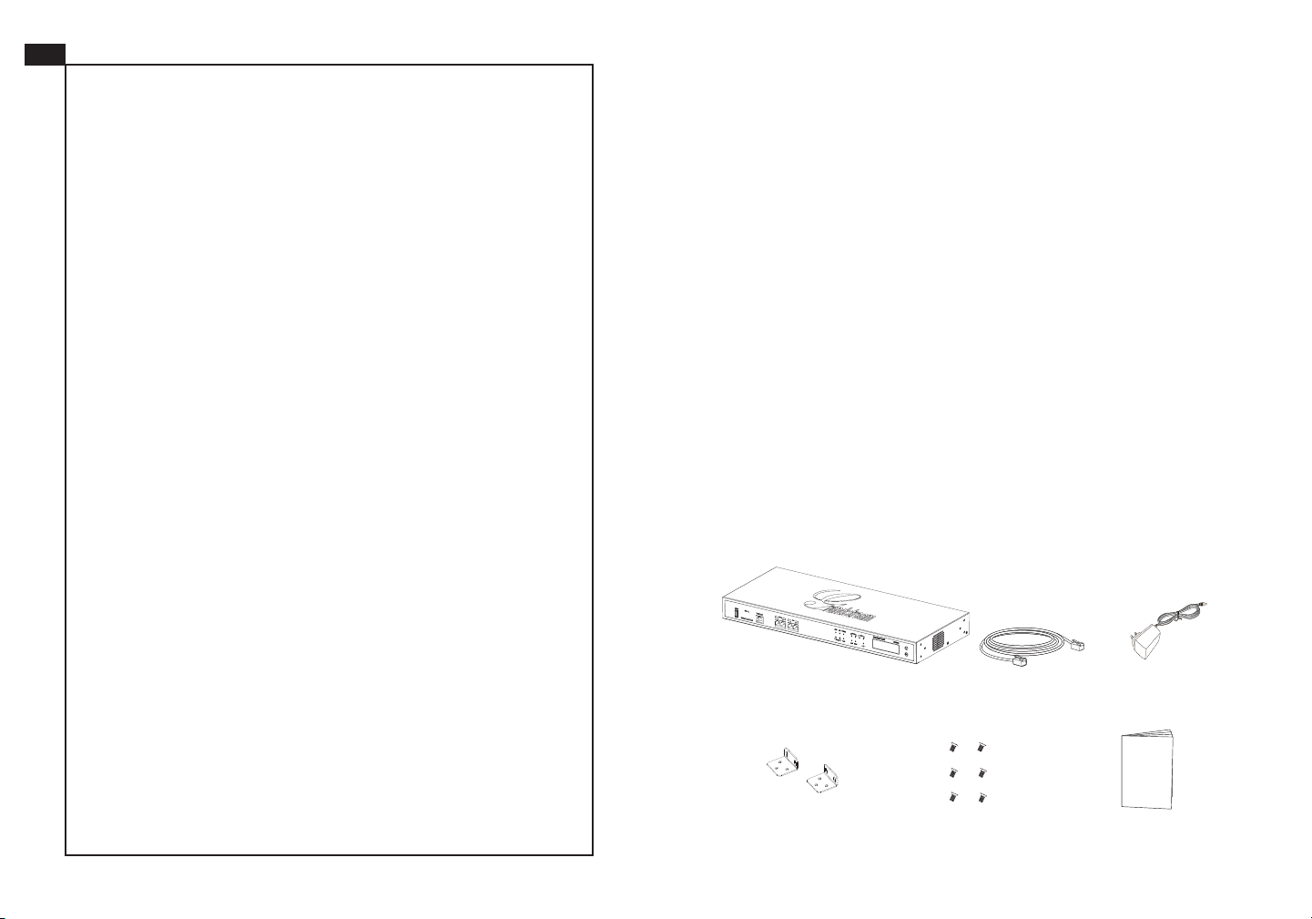
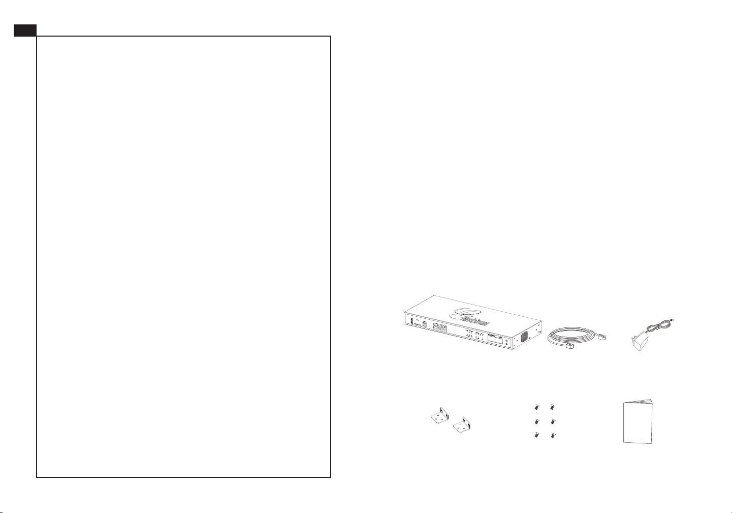
PACKAGE CONTENTS:
12V
1 X UCM6510 Main Case 1 X Ethernet Cable
2 X 12V Power Adapter
6 X Screws2 X Wall Mount
1 X Quick Installation Guide
1 2
Page 4
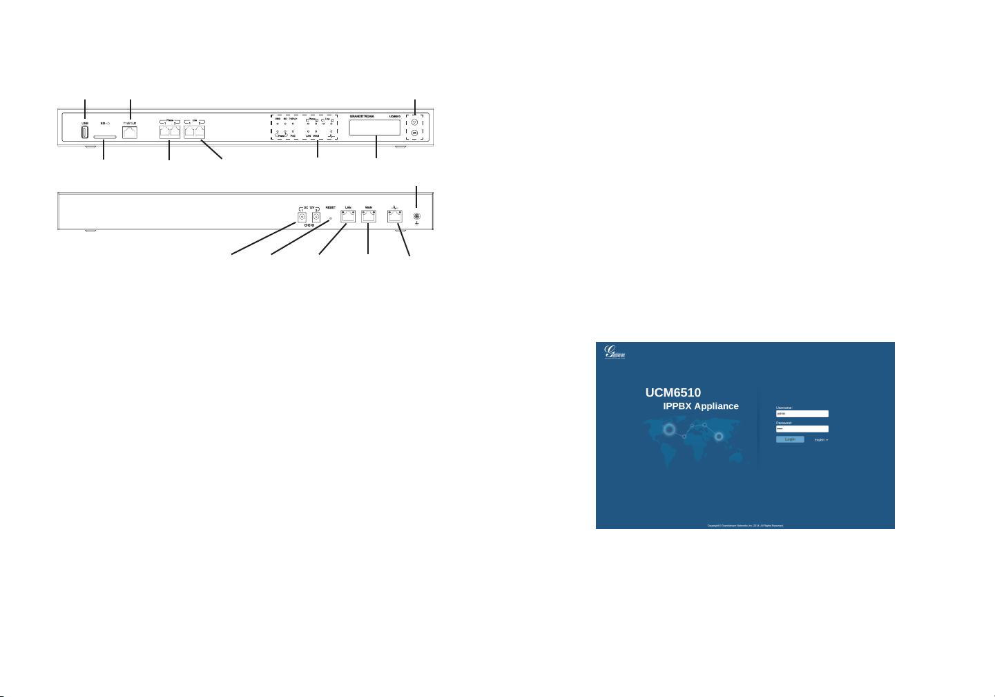
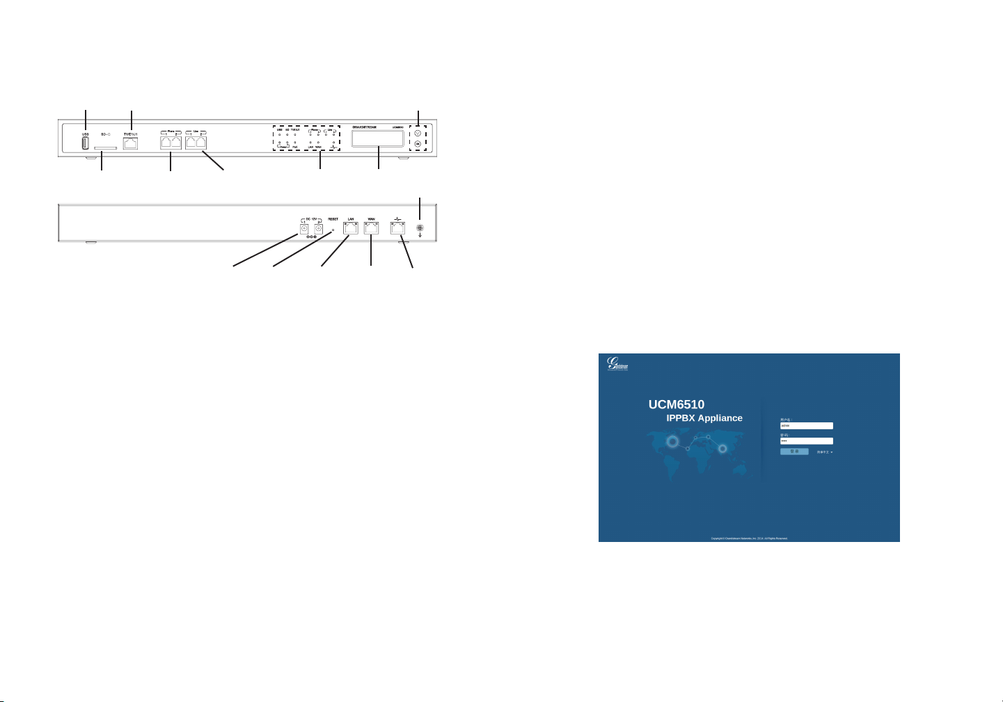
CONNECTING THE UCM6510:
USING THE UCM6510 KEYPAD MENU:
USB Port
SD Card Slot
Basic connections for intial setup:
1. Connect one end of an RJ-45 Ethernet cable (cable type: straight through) into
the WAN port of the UCM6510; connect the other end into the uplink port of an
Ethernet switch/hub.
2. Connect the 12V DC power adapter into the DC 12V power jack 1 on the back of
the UCM6510. Insert the main plug of the power adapter into a surge-protected
power outlet. (Connect the second power adapter into the DC 12V power jack 2
for failover purpose in case the rst one is down).
3. Wait for the UCM6510 to boot up. The LCD in the front will show its hardware
information when the bootup process is done.
4. Once the UCM6510 is successfully connected to the network, the LED indicator
for the WAN port in the front will be in solid green and the LCD shows up the IP
address.
T1/E1/J1 Port
2 x FXS Port
2 x DC 12V Power Jack
2 x FXO Port
Reset
LED Indicators
LAN Port
WAN Port
Navigation Keys
LCD
Ground
Heartbeat
Port
1. Press “OK” key to start browsing menu options.
2. Press “Down” to browser different menu options. Press “OK” to select an entry.
3. In the menu option, select “Back” to go back to previous menu.
4. The LCD will return to default display after being idle in menu for longer than 20
seconds.
CONFIGURING THE UCM6510 VIA WEB GUI:
1. Connect the computer to the same network as the UCM6510.
2. Ensure the UCM6510 is properly powered up and shows its IP address in the
LCD.
3. Open a web browser in the computer and enter the IP address in the address
bar.
4. The web GUI login page will be shown as the gure below. The default user
name and password for administrator are “admin”.
Optional connections depending on how the UCM6510 is used:
1. PSTN Line Connection: connect PSTN lines from the wall jack to the UCM6510
LINE ports (FXO ports).
2. Analog Line Connection: connect analog lines (phone and fax) to the PHONE
ports (FXS ports).
3. T1/E1/J1 Line Connection: connect one end of the T1/E1/J1 cable provided from
the service provider into the T1/E1/J1 port of the UCM6510; connect the other
end into the T1/E1/J1 wall jack.
5. For the detailed information to congure SIP Extensions, PSTN lines, SIP trunks
and all the other system settings via web GUI, please download the UCM6510
user manual here:
http://www.grandstream.com/support
3 4
Page 5
ZH
UCM6510不预设对医院,执法机构,医疗中
心(急救服务)以及各种紧急服务的紧急通话服
务。用户必须自行设定紧急通话功能。用户必
须自行购买SIP兼容的网络电话服务,正确的设
定UCM6510使用该服务,并定期测试您的配
置以确保UCM6510如预期工作,否则请购买
传统无线或有线电话服务来拨打紧急通话。
Grandstream Networks 公司的UCM6510不支
持紧急通话服务。Grandstream Networks公
司、其管理者和员工以及其相关机构对此所造
成的任何索赔、损失或者损害都不负有任何法
律追究责任。在此,您将无权对任何以及所有
由于无法通过UCM6510拨打紧急电话以及没
有遵照前段文字描述而造成紧急通话失败的事
件提出诉讼。
注意事项:
1. 请不要拆卸或修改该设备。
2. 请不要使用第三方的电源适配器。
3. 请不要在超出0至45摄氏度的环境下使用该设备;请不要在超出-10至60摄氏度
的环境下存储该设备。
4. 请不要将设备暴露在超出相对湿度10%-90%范围外的环境下。
5. 请不要在设备启动未完成的时候或设备的软件升级过程中断开电源。如上所述
的操作会导致话机本身的程序损坏,进而造成设备无法启动。
产品概览:
UCM6510是一款为中小型企业设计的融合通信与安全性能、管理便捷、兼具创新
的企业级IPPBX设备。它采用了先进的硬件平台和丰富的软件功能,无额外软件
Licence费用,为用户提供了集语音、视频、数据、传真、安全监控和移动设备需
求的统一解决方案。
设备包装清单:
12V
UCM6510主机(1台)
墙体支架工具(2个)
网线(1根)
螺丝(6个)
电源适配器(2个)
快速安装手册(1本)
5 6
Page 6
连接UCM6510:
使用UCM6510菜单按键:
USB端口
基本连接(可用于首次配置):
1.将RJ45以太网线(网线类型:直通线)的一端连接UCM6510的WAN端口,另
一端连接以太网交换机或集线器上行链接的RJ-45网络接口。
2.用12V电源适配器连接UCM6510电源接口1和交流电源插座。用户可使用第二
个电源适配器将电源接口2也连接上,用于电源故障切换。
3.等待设备启动。启动完成后,UCM6510的LCD显示屏上将会显示设备硬件信
息。
4.等待设备网络连接完成。连接成功后,UCM6510的WAN端口LED指示灯将会
持续显示绿色,LCD将会显示设备IP地址。
SD卡插槽
T1/J1/E1端口
12V电源接口(2个)
FXO端口(2个)
重置
LED指示灯FXS端口(2个)
LAN端口
WAN端口 心跳端口
菜单按键
LCD显示屏
接地端
1.按“OK”键开始浏览菜单。
2.按“下”键浏览菜单各选项;按“OK”键选择菜单选项。
3.选择菜单中的“Back”选项返回上一级菜单。
4.在菜单中,若空闲状态停留20秒后,LCD将会回到默认显示。
通过网络界面配置UCM6510:
1.将电脑与UCM6510连接至同一网络。
2.UCM6510正常启动并成功连接网络后,在LCD上确认UCM6510的IP地址。
3.在电脑的网络浏览器地址栏中,输入UCM6510的IP地址。
4.UCM6510网络登录界面如下图所示。默认用户名和密码均为“admin”。
可选连接(根据实际使用情况):
1.PSTN连接:将PSTN电话线连接至UCM6510的LINE端口(即FXO端口)。
2.模拟电话/传真连接:将模拟电话线或传真机线连接至UCM6510的PHONE端
口(即FXS端口)。
3.T1/E1/J1连接:将服务提供商/运营商提供的T1/E1/J1线缆连接至UCM6510的
T1/E1/J1端口。
5.登录后,用户可以在网络界面下配置SIP账号、PSTN连接、SIP中继、系统设定
等。欲获取更多详细信息,请在如下链接下载UCM6510用户手册:
http://www.grandstream.com/support
7 8
Page 7

ES
El UCM6510 no viene pre congurado ni tiene acceso a información de ningún tipo de servicio de llamadas de emer-
gencia, hospitales, servicios policiales, unidades de cuidados médicos o cualquier otro tipo de servicio de socorro.
Usted deberá hacer las coordinaciones necesarias para
poder acceder a estos servicios. Será su responsabilidad, el
contratar el servicio de telefonía por internet compatible con
el protocolo SIP, congurar apropiadamente el UCM6510
para usar dicho servicio y periódicamente, probar su conguración para conrmar su funcionamiento de acuerdo a
sus expectativas. Si usted decide no hacerlo, será su responsabilidad comprar servicios de telefonía tradicional, ya
sea por línea ja o inalámbrica para poder acceder a los
servicios de emergencia.
GRANDSTREAM NO PROVEE CONEXIONES CON
NINGUN SERVICIO DE EMERGENCIA MEDIANTE EL
UCM6510. NI GRANDSTREAM NI SUS DIRECTORES,
EMPLEADOS O AFILIADOS, PUEDEN SER SUJETOS
REPONSABLES POR NINGUN RECLAMO, DAÑO O
PERDIDA. POR LO TANTO, POR LA MEDIANTE, USTED
RENUNCIA A SU DERECHO DE RECLAMO O DENUNCIA
QUE PUEDA SURGIR DEBIDO A LAS LIMITACIONES EN
EL USO DEL UCM6510 PARA CONTACTAR A LOS SERVICIOS DE EMERGENCIA, ASI COMO A SU NEGLIGENCIA
DE REALIZAR LAS COORDINACIONES NECESARIAS
PARA ACCEDER A TODOS LOS SERVICIOS DE EMERGENCIA, MENCIONADOS EL PARRAFO PRECEDENTE.
PRECAUCIONES:
• No abrir, desarmar o intentar modicar este equipo.
• No use adaptadores de corriente distintos al suministrado.
• No exponga este dispositivo a temperaturas fuera del rango de 0 °C a +45 °C en
funcionamiento y desde -10 °C a +60 °C cuando este almacenado.
• No exponga este dispositivo ambientes fuera del siguiente rango de humedad:
10%-90% RH (Sin condensación).
• Por favor NO apague el UCM6510 durante el arranque o durante la actualización
del rmware. La interrupción de la actualización del rmware puede causar mal
funcionamiento del equipo.
INFORMACIÓN GENERAL:
UCM6510 es un innovador IP PBX diseñado para llevar a un nivel empresarial
las comunicaciones unicadas con características de protección de seguridad
avanzadas para las pequeñas y medianas empresas (pymes) de una manera fácil
de administrar. Desarrollado con una plataforma de hardware avanzada y funcionalidades de software revolucionarios, El UCM6510 ofrece una solución completa
para la convergencia de voz, vídeo, datos, fax, vídeo vigilancia y aplicaciones de
movilidad sin ningún tipo de licencias adicionales o costos recurrentes.
CONTENIDO DEL PAQUETE:
12V
1 X UCM6510 1 X Cable de Red 2 X Adaptador de
Alimentación de 12V
2 X Montura de rack
6 X Tornillos
1 X Guía de
instalación rápida
9 10
Page 8

CONECTANDO EL UCM6510:
Puerto USB
Ranura de
tarjeta SD
1 X Puerto T1/E1/J1
2 x Puertos
FXS
2 x Puertos
FXO
Teclas de Navegación
Indicadores
LED
Pantalla
LCD
Tierra
USO DEL MENÚ A TRAVÉZ DEL TECLADO DEL
UCM6510:
1. Pulse el botón “OK” para comenzar a navegar por las opciones del menú.
2. Pulse el botón “Bajar” para navegar por las diferentes opciones del menú. Pulse
el botón “OK” para seleccionar una entrada.
3. En la opción del menú, seleccione “Volver” para regresar al menú anterior.
4. La pantalla LCD volverá a la pantalla por defecto (de inicio) después de estar
inactiva durante más de 20 segundos.
CONFIGURACION DEL UCM6510 ATRAVEZ DE LA
INTERFAZ WEB DE USUARIO
2 x Conectores DC 12V
Conexiones básicas para la conguración inicial:
1. Conecte un extremo de un cable Ethernet RJ-45 en el puerto WAN del UCM6510;
conecte el otro extremo en el puerto de enlace de un switch/hub.
2. Conecte el adaptador de corriente de 12 V CC en el conector de alimentación
1 DC 12V en la parte posterior de la UCM6510. Inserte el enchufe principal
del adaptador de corriente en un toma corriente protegido contra sobre tensio nes. (Conecte el segundo adaptador de alimentación en el conector de alimen tación 2 DC 12V para nes de conmutación cuando el primero falle).
3. Espere a que el UCM6510 inicie. La pantalla LCD en la parte frontal mostrará la
información de hardware cuando el proceso de arranque comienza.
4. Una vez que el UCM6510 está correctamente conectado a la red, el indicador
LED para el WAN en la parte frontal estará en color verde y en la pantalla apa-
rece la dirección IP asignada.
Conexiones opcionales del UCM6510:
1. Conexión de línea PSTN: conecte las líneas PSTN desde la toma de la pared a
los puertos LINE del UCM6510 (puertos FXO).
2. Conexión de lineas analógicas: Conecte las lineas analógicas (Teléfonos y Fax)
a los puertos PHONE (puertos FXS).
3. Conexión de lineas T1/E1/J1: conecte un extremo del cable T1/E1/J1 proporcio nado por el proveedor de servicios en el puerto T1/E1/J1 del UCM6510; conecte
el otro extremo en el enchufe de la pared T1/E1/J1.
Resetear
Puerto
LAN
Puerto
WAN
Puerto de
monitoreo
1. Conecte un ordenador a la misma red que el UCM6510.
2. Asegúrese de que el UCM6510 está correctamente encendido y muestra su
dirección IP en la pantalla LCD.
3. Abra un navegador web en el ordenador y escriba la dirección IP en la barra de
direcciones.
4. La página web de inicio de sesión GUI mostrará (ver gura más adelante). El
nombre de usuario y contraseña por defecto para el administrador es “admin”.
5. Para la información detallada de las conguraciones de extensiones SIP, líneas
PSTN, troncos SIP y todos los ajustes del sistema a través de la interfaz Web
GUI, por favor descargue el manual de usuario UCM6510 desde aquí.
http://www.grandstream.com/support
11 12
Page 9

FR
Le UCM6510 n’est pas préconguré pour prendre en
charge ou de procéder les appels d’urgence à tout
type d’hôpital, d’application de la loi, ou unité de soins
médicaux (“Service (s) d’urgence”) ou tout autre type
de service d’urgence. Vous devez faire des arrangements pour l’accès aux services d’urgence. C’est
votre responsabilité d’acheter un service téléphonique
Internet compatible SIP, congurer correctement le
UCM6510 à utiliser ce service et, périodiquement, de
tester votre conguration an de conrmer qu’il fonctionne comme prévu. Si vous ne le faites pas, c’est
votre responsabilité d’acheter un accès au service téléphonique traditionnel sans l ou laire an d’accéder
aux services d’urgence.
GRANDSTREAM NE FOURNIT AUCUNE CONNEXION AUX SERVICES D’URGENCE VIA LE UCM6510.
NI GRANDSTREAM, NI SES DIRIGEANTS, EMPLOYES OU FILIALES PEUVENT ETRE TENUS RESPONSABLE POUR TOUTE RECLAMATION OU CAUSE
D’ACTION DECOULANT OU RELATIF A VOTRE INCAPACITE D’UTILISER LE UCM6510 POUR CONTACTER LES SERVICES D’URGENCE ET VOTRE
ECHEC DE FAIRE DES ARRANGEMENTS SUPPLEMENTAIRES POUR ACCEDER AUX SERVICES
D’URGENCE EN CONFORMITE AVEC LE PARAGRAPHE PRECEDENT.
PRECAUTIONS:
• Ne pas tenter d’ouvrir, de désassembler, ou de modier le dispositif.
• Ne pas utiliser un adaptateur d’alimentation tiers.
• Ne pas exposer cet appareil à des températures hors de la plage de 0 °C à
+45 °C en opération ou -10 °C à +60 °C en stockage.
• Ne pas exposer cet appareil à un environnement avec humidité hors de la plage
de 10%-90% RH (sans condensation).
• Veuillez ne pas éteindre le UCM6510 pendant le démarrage du système ou la
mise à jour du rmware. Cela risque de rompre l’image du rmware et en consé quence rendre l’unité inutilisable.
PRESENTATION:
UCM6510 est est une Appliance IP PBX innovatrice, conçue pour offrir des communications uniées de classe entreprise et des fonctions de sécurité pour les
petites et moyennes entreprises (PME) faciles à administrer. Propulsée par une
plate-forme matérielle de pointe et des fonctionnalités logicielles révolutionnaires,
la série UCM6510 offre une solution clé en main pour la convergence voix, vidéo,
données, fax, surveillance de la sécurité, et des applications de mobilité prêtes à
l’emploi, sans frais de licence supplémentaires ou coûts récurrents.
CONTENU DU PACK:
12V
1 X UCM6510 Boîtier Principal 1 X Câble Ethernet
2 X 12V
Adaptateur Secteur
6 X Vis2 X Montage mural
1 X Guide d’installation rapide
13 14
Page 10

CONNECTER LE UCM6510:
UTILISATION DU CLAVIER MENU DU UCM6510:
Port USB
Port Carte
SD
2 x Adaptateur Secteur 12V DC
Connexions basiques pour installation initiale:
1. Connectez l’extrémité d’un câble Ethernet RJ45 ( type de câble: droit) au port
WAN de l’UCM6510; connectez l’autre extrémité au port ascendant d’un Switch/
hub Ethernet.
2. Connectez l’adaptateur 12V DC au port 1 d’alimentation 12V DC à l’arrière de
l’UCM6150. Insérez le Plug principal de l’adaptateur d’alimentation dans la prise
d’alimentation protégée contre la surtension. (Connectez le deuxième adaptat eur au port 2 d’alimentation 12V DC pour basculement dans le cas où le premier
tombe en panne).
3. Attendez que le UCM6510 démarre. L’écran LCD à l’avant afchera ses informa tions matérielle lorsque le processus de démarrage est terminé.
4. Une fois que le UCM6510 est connecté au réseau, le voyant LED WAN à l’ avant
sera en vert et l’écran LCD afchera l’adresse IP.
1 X Port T1/E1/J1
2 x Ports
FXS
2 x Ports
FXO
Réinitialisation
Boutons de Navigation
Indicateurs
LED
Port
LAN
LCD
Port
WAN
Terre
Port de
Pulsation
(Hearbeat)
1. Appuyez sur “OK” pour commencer à parcourir les options du menu.
2. Appuyez sur “Bas” pour parcourir les différentes options du menu. Appuyez
sur “OK” pour sélectionner une entrée.
3. Dans le menu, sélectionnez “Retour” pour revenir au menu précédent.
4. L’écran LCD revient à l’afchage par défaut après avoir été inactif dans le menu
pendant plus de 20 secondes.
CONFIGURATION DU UCM6510 VIA
L’INTERFACE WEB:
1. Connectez l’ordinateur au même réseau que le UCM6510.
2. S’assurer que le UCM6510 est bien sous tension et afche son adresse IP dans
l’écran LCD.
3. Ouvez un navigateur Web dans l’ordinateur et entrez l’adresse IP dans la barre
d’adresse.
4. La page de connexion apparaîtra (voir la gure ci-dessous). Par defaut, Le nom
d’utilisateur et le mot de passe administrateur sont «admin».
Connexions facultatives dependant de l’usage de l’UCM6510:
1. Connexion de ligne RTC: Connectez les lignes RTC à partir de la sortie murale
aux ports Ligne de l’UCM6510 (Ports FXO).
2. Connexion de ligne Analogique: Connectez les lignes analogiques (téléphone et
fax) aux ports Téléphone (Ports FXS).
3. Connexion de ligne T1/E1/J1: Connectez l’extrémité du câble T1/E1/J1 fourni
par le fournisseur de services au port T1/E1/J1 de l’UCM6510, Connectez l’aut re extrémité au port mural T1/E1/J1.
5. Pour des informations détaillées concernant la conguration des extensions
SIP, lignes RTC, Trunks SIP et tous les autres paramètres du système via l’inter face Web, Veuillez télécharger le manuel d’utilisation du UCM6510 à partir d’ici.
http://www.grandstream.com/support
15 16
Page 11

DE
Das UCM6510 ist nicht für die Durchführung von Notrufen
an Krankhäuser, Strafverfolgungsbehörden, medizinische
Pegeeinrichtungen (“Notdienste”) oder jegliche andere
Form von Notdiensten ausgerichtet. Sie müssen zusätzliche Einstellungen vornehmen, um Zugang zu Notdiensten
zu erhalten. Es liegt an Ihnen, einen SIP-kompatiblen Internettelefoniedienst zu erwerben, das UCM6510 korrekt für
die Nutzung dieses Dienstes zu kongurieren und die Kongurierung regelmäßig auf ihre Funktionstüchtigkeit zu testen. Andernfalls liegt es an Ihnen, herkömmliche Drahtlosoder Festnetztelefoniedienste zu erwerben, um Zugang zu
Notdiensten zu erhalten.
GRANDSTREAM BIETET ÜBER DAS UCM6510 KEINE
VERBINDUNG ZU NOTRUFEN AN. WEDER DAS UNTERNEHMEN GRANDSTREAM NOCH SEINE FUNKTIONÄRE, ANGESTELLTEN ODER PARTNER KÖNNEN
FÜR FORDERUNGEN, SCHADEN ODER VERLUSTE
HAFTBAR GEMACHT WERDEN. SIE VERZICHTEN
HIERMIT AUF JEGLICHE UND ALLE SOLCHE FORDERUNGEN ODER RECHTLICHEN SCHRITTE, DIE DURCH
DIE UNMÖGLICHKEIT, ÜBER DAS UCM6510 NOTRUFE
ZU NUTZEN, SOWIE DURCH IHR VERSÄUMNIS, DIE
GEMÄß DEM VORHERGEHENDEN PARAGRAPH NOTWENDIGEN ZUSÄTZLICHEN EINSTELLUNGEN FÜR
DEN ZUGANG ZU NOTRUFEN VORZUNEHMEN, VERURSACHT WERDEN KÖNNEN.
VORSICHTSMAßNAHMEN:
• Versuchen Sie nicht, das Gerät zu öffnen, zu zerlegen oder zu modizieren.
• Verwenden Sie keine Netzteile von anderen Herstellern.
• Das Gerät darf nicht bei Temperaturen jenseits von 0 °C bis +45 °C betrieben
oder gelagert werden von -10 °C bis +60 °C.
• Die Luftfeuchtigkeit muss innerhalb des folgenden Bereichs liegen: 10%-90% rel.
Luftfeuchtigkeit (nichtkondensierend).
• Schalten Sie das UCM6510 beim Systemstart oder bei der Firmware-Aktualisier
ung NICHT aus und wieder ein. Andernfalls können Firmware-Bilder beschädigt
werden und es könnten Funktionsstörungen am Gerät auftreten.
ÜBERSICHT:
Die innovative IP-Telefonanlage UCM6510 stellt den Ausstattungsumfang von Anlagen für Großkunden ab sofort auch kleinen und mittelständischen Unternehmen
zur Verfügung. Die Hochleistungsplattform der UCM6510 bietet bahnbrechende
Softwarefunktionen und perfekte Konvergenz von Sprache, Daten, Video, Fax,
Sicherheits- und mobilen Applikationen. Die UCM6510 stellt alle Funktionen in der
Grundausstattung zur Verfügung, es fallen keine Lizenz-oder andere, wiederkehrende Kosten an.
PACKUNGSINHALT:
12V
1 X UCM6510
1 X Ethernet-Kabel
2 X 12V Netzteil
2 X Wandhalterung
6 X Schrauben
1 X Schnellinstallationsanleitung
17 18
Page 12

UCM6510 ANSCHLIESSEN:
VERWENDUNG DES UCM6510-TASTENFELDMENÜS:
USB-Anschluss
SD Card
Slot
2 x DC 12V Stromanschluss
Basisanschlüsse für die initialen Einstellungen:
1. Schließen Sie ein Ende des RJ-45 Netzwerkkabels (Typ 1:1 Standard) am
WAN-Port der UCM6510, das andere Ende am Netzwerk Switch / Hub an.
2. Schließen Sie das mitgelieferte 12V Netzteil an der Rückseite der UCM6510 an.
Anschließend stecken Sie das andere Ende in die Steckdose. (Schließen Sie
das zweite Netzteil an einem anderen Stromkreislauf an, es kann dann die
Stromzufuhr bei Ausfall des ersten Netzteils übernehmen).
3. Warten Sie, bis das UCM6510 gestartet wurde. Nach dem Startvorgang werden
die Hardwareinformationen auf dem LCD auf der Vorderseite angezeigt.
4. Sobald das UCM6510 ordnungsgemäß mit dem Netzwerk verbunden wurde,
leuchtet die LED für WAN auf der Vorderseite grün und auf dem LCD
wird die IP-Adresse angezeigt.
1 X T1/E1/J1 Anschluss
2 x FXS-
Anschluss
2 x FXOAnschluss
Zurücksetzen
LEDAnzeigen
LANAnschluss
Navigationstasten
LCD
Erdung
WAN-
Anschluss
NotfallPort
1. Drücken Sie die OK, um durch die Menüoptionen zu navigieren.
2. Drücken Sie die Abwärtstaste, um zu anderen Menüoptionen zu wechseln.
Drücken Sie OK, um einen Eintrag auszuwählen.
3. Wählen Sie in der Menüoption „Zurück“, um zum vorherigen Menü zu wechseln.
4. Bei mehr als 20 Sekunden ohne Aktivität wird auf dem LCD wieder die Standar
danzeige angezeigt.
KONFIGURIEREN DES UCM6510 ÜBER DIE WEB-GUI
1. Schließen Sie den Computer an dasselbe Netzwerk an wie das UCM6510.
2. Vergewissern Sie sich, dass das UCM6510 eingeschaltet ist und die IP-Adresse
im LCD angezeigt wird.
3. Öffnen Sie auf dem Computer einen Webbrowser und geben Sie die URL für die
Web-GUI im folgenden Format ein:
http(s)://IP-Adresse:Port
Das Standardprotokoll ist HTTPS und die Standardportnummer ist 8089.
4. Die Anmeldeseite der Web-GUI wird angezeigt (siehe Abbildung). Der Standar dbenutzername und das Standardkennwort für den Administrator lauten
„admin“.
Weitere Anschlüsse, je nach Nutzung der UCM6510:
1. Analoger Amt-Anschluss: Schließen Sie das analoge Kabel am FXO-Anschluss
der UCM6510, und das andere Ende an der analogen Wandsteckdose an.
2. Analoger Anschluss: Schließen Sie die analogen Endgeräte (Telefone, Fax) an
die FXO Ports der UCM6510.
3. T1/E1/J1 Anschluss: Schließen Sie ein Ende des Netzwerkkabels am T1/E1/J1
Port der UCM6510, das andere Ende an der T1/E1/J1 Anschlussdose des
Service-Providers an.
5. Ausführliche Informationen zum Kongurieren der SIP-Nebenstellen, Festnet zleitungen, SIP-Leitungen und allen anderen Systemeinstellungen über die
Web-GUI nden Sie im UCM6510-Benutzerhandbuch, das Sie hier herunter laden können.
http://www.grandstream.com/support
19 20
Page 13

IT
UCM6510 non è precongurato per supportare o effettuare chiamate di emergenza a qualsiasi tipo di ospedale, struttura giudiziaria, unità di assistenza medica (“Servizi di emergenza”) o a qualsiasi altro tipo di
servizio di emergenza. È necessario effettuare accordi
supplementari per accedere ai Servizi di emergenza.
È a Vostra esclusiva responsabilità acquistare servizi di telefonia internet conformi con SIP, congurare
UCM6510 correttamente per usare tale servizio ed effettuare test periodici della congurazione per assicurarsi che funzioni in modo idoneo. Se non si effettua
ciò, è Vostra responsabilità acquistare servizi telefonici
ssi o wireless tradizionali per accedere ai Servizi di
emergenza.
GRANDSTREAM NON FORNISCE COLLEGAMENTI AI SERVIZI DI EMERGENZA ATTRAVERSO
UCM6510. NÈ GRANSTREAM NÈ I SUOI RESPONSABILI, DIPENDENTI O AFFILIATI POSSONO ESSERE RITENUTI RESPONSABILI DI QUALSIASI
RECLAMO, DANNO O PERDITA, E DI QUALSIASI
AZIONE LEGALE DERIVANTE DA TALI RECLAMI O
CAUSE IN RELAZIONE ALL’IMPOSSIBILITÀ DI USARE IL UCM6510 PER CHIAMATE AI SERVIZI O DI
STRINGERE ACCORDI SUPPLEMENTARI PER ACCEDERE AI SERVIZI DI EMERGENZA IN CONFORMITÀ AL PARAGRAFO PRECEDENTE.
PRECAUZIONI:
• Non tentare di aprire, smontare o modicare il dispositivo.
• Non utilizzare un adattatore di alimentazione di terzi.
• Non esporre il dispositivo a temperature non incluse nell’intervallo da 0 °C a
+45 °C per l’operatività o da -10 °C a +60 °C per l’immagazzinaggio.
• Non esporre il dispositivo ad ambienti non inclusi nel seguente intervallo di
umidità: 10% - 90 % di umidità relativa (senza condensa)
• NON spegnere e riaccendere il UCM6510 durante l’avvio del sistema o l’aggiorna mento del rmware. Si possono corrompere le immagini del rmware e causare
problemi di funzionamento.
PANORAMICA:
UCM6510 è un apparato IP PBX innovativo progettato per portare, a livello enterprise, le funzioni di Protezione e comunicazione unicata alle piccole e medie imprese (SMB) in un modo facile da gestire. Alimentato da una piattaforma
hardware avanzata e da rivoluzionare funzionalità software, UCM6510 offre una
innovativa soluzione precongurata per le applicazioni vocali, video, dati, fax, sorveglianza e mobilità senza costi per licenze extra o spese ricorrenti.
CONTENUTO DELLA CONFEZIONE:
12V
1 X UCM6510
Apparecchi principale
1 X Cavo Ethernet
2 X 12V Alimentatore
6 X Viti2 X Montaggio a Parete
1 X Guida di installazione rapida
21 22
Page 14

CONNESSIONE DEL UCM6510:
UTILIZZO DEL MENU DEL TASTIERINO DI UCM6510:
Porta USB
Slot per
SD Card
2 x Jack alimentatore CC 12V
Collegamenti di base per la congurazione iniziale:
1. Collegare l’estremità di un cavo Ethernet RJ-45 (tipo di cavo: diretto) alla porta
WAN di UCM6510; collegare l’altra estremità alla porta uplink di uno switch/hub
Ethernet.
2. Collegare l’adattatore di alimentazione 12V CC al jack 1 dell’alimentatore CC
12V sul retro di UCM6510. Inserire il connettore principale dell’adattatore di ali mentazione in una presa elettrica protetta da sovracorrente. (Collegare il secon do adattatore di alimentazione al jack 2 dell’alimentatore CC 12V per scopi di
failover, nel caso in cui il primo non dovesse funzionare).
3. Attendere l’avvio di UCM6510. Quando il processo di avvio sarà completato, sul
display LCD anteriore verranno visualizzate le informazioni relative all’hardware.
4. Una volta che UCM6510 è connesso correttamente alla rete, l’indicatore LED
della WAN nella parte anteriore sarà di colore verde e il display LCD visualizzerà
l’indirizzo IP.
Collegamenti opzionali a seconda della modalità di utilizzo di UCM6510:
1. Collegamento della linea PSTN: collegare le linee PSTN dal jack a parete alle
porte LINE di UCM6510 (porte FXO).
2. Collegamento linea analogica: collegare le linee analogiche (telefono e fax) alle
porte PHONE (porte FXS).
3. Collegamento della linea T1/E1/J1: collegare un’estremità del cavo T1/E1/J1
fornito dal fornitore del servizio alla porta T1/E1/J1 di UCM6510; collegare l’altra
estremità nel jack a parete T1/E1/J1.
1 X Porta T1/E1/J1
2 x Porte
FXS
2 x Porte
FXO
Ripristina
Indicatori
LED
Due porte
LAN
Tasti di navigazione
LCD
Messa a terra
Due porte
WAN
Porta
Heartbeat
1. Premere il tasto “OK” per iniziare a scorrere le opzioni del menu.
2. Premere “Giù” per scorrere le diverse opzioni del menu. Premere “OK” per
selezionare una voce.
3. Nell’opzione di menu, selezionare “Indietro” per tornare al menu precedente.
4. Il display LCD tornerà alla visualizzazione predenita dopo un periodo di inat tività nel menu di più di 20 secondi.
CONFIGURAZIONE DI UCM6510 TRAMITE
INTERFACCIA UTENTE GRAFICA WEB:
1. Collegare il computer alla stessa rete di UCM6510.
2. Assicurarsi che UCM6510 sia alimentato correttamente e visualizzi l’indirizzo IP
sul display LCD.
3. Aprire un browser Web nel computer e immettere l’indirizzo IP nella barra degli
indirizzi.
4. Verrà visualizzata la pagina di accesso dell’interfaccia utente graca Web
(vedere la gura sotto). Il nome utente e la password amministratore predeniti
sono “admin”.
5. Per informazioni dettagliate su come congurare le estensioni SIP, le linee
PSTN, i trunk SIP e tutte le altre impostazioni di sistema tramite l’interfaccia
utente graca Web, scaricare qui il manuale utente di UCM6510.
http://www.grandstream.com/support
23 24
Page 15

RU
UCM6510 не предназначен для поддержки и
выполнения срочных звонков в медицинские
учреждения, правоохранительные органы, учреждения
здравоохранения (“Экстренные службы”) и в какие-либо
другие экстренные службы. Для доступа к экстренным
службам необходимо предпринять дополнительные
меры. Приобретение SIP-совместимой услуги Интернет
телефонии, надлежащая конфигурация UCM6510 для
использования данной услуги и периодическая проверка
конфигурации с целью подтверждения правильности
работы являются обязанностью заказчика. Если это
не сделано, то для доступа к экстренным службам
необходимо подключиться к услугам беспроводной или
проводной телефонной связи.
GRANDSTREAM НЕ ПРЕДОСТАВЛЯЕТ ПОДКЛЮЧЕНИЕ
К ЭКСТРЕННЫМ СЛУЖБАМ ЧЕРЕЗ UCM6510. КРОМЕ
ТОГО, НИ КОМПАНИЯ GRANDSTREAM, НИ ЕЕ
РУКОВОДИТЕЛИ, СОТРУДНИКИ И АФФИЛИРОВАННЫЕ
ЛИЦА НЕ НЕСУТ ОТВЕТСТВЕННОСТИ В СЛУЧАЕ
КАКИХ-ЛИБО ПРЕТЕНЗИЙ, УЩЕРБА ЛИБО ПОТЕРЬ,
И ВЫ ТЕМ САМЫМ ОТКАЗЫВАЕТЕСЬ ОТ КАКИХЛИБО
ТРЕБОВАНИЙ ИЛИ ОСНОВАНИЙ ДЛЯ ИСКА,
ЯВЛЯЮЩИХСЯ РЕЗУЛЬТАТОМ ИЛИ КАСАЮЩИХСЯ
ВАШЕЙ НЕСПОСОБНОСТИ ИСПОЛЬЗОВАТЬ UCM6510,
ЧТОБЫ СВЯЗАТЬСЯ С АВАРИЙНЫМИ СЛУЖБАМИ
И ВАШИМ ОТКАЗОМ СДЕЛАТЬ ДОПОЛНИТЕЛЬНЫЕ
ПРИГОТОВЛЕНИЯ, ЧТОБЫ ПОЛУЧИТЬ ДОСТУП
К АВАРИЙНЫМ СЛУЖБАМ В СООТВЕТСТВИИ С
ПРЕДЫДУЩИМ ПАРАГРАФОМ.
МЕРЫ ПРЕДОСТОРОЖНОСТИ:
• Не пытайтесь открывать, разбирать или изменять устройство.
• Не используйте адаптер питания другого производителя.
• Не допускается использование устройства при температурах вне диапазона
от 0 °C до +45 °C при эксплуатации и от -10 °C до +60 °C при хранении.
• Не допускается выставлять устройство наружу при относительной
влажности вне диапазона 10%-90% (без конденсата).
• Не следует выключать/включать UCM6510 во время загрузки системы или
обновления микропрограммного обеспечения. Возможно повреждение
встроенных программ, что приведет к поломке устройства.
ОБЩИЙ ОБЗОР:
UCM6510 - инновационная IP-АТС, созданная для того, чтобы дать малым
и средним предприятиям возможность пользоваться первоклассными
функциями объединенных коммуникаций и защиты безопасности, ранее
доступных только крупным предприятиям, в простой в управлении форме.
Построенная на продвинутой аппаратной платформе и революционном
программном функционале, UCM6510 предлагает готовое решение,
которое объединяет в себе передачу голоса, видео, данных, факс,
мониторинг безопасности и мобильные приложения сразу при покупке без
дополнительных лицензионных сборов и периодических платежей.
КОМПЛЕКТ ПОСТАВКИ:
12V
1 X корпус UCM6510 1 X кабель Ethernet
2 X 12V адаптер
питания 12 В
2 X подставка для
крепежа на стену
6 X Шурупа
1 X Руководство по
быстрой установке
25 26
Page 16

ПОДКЛЮЧЕНИЕ UCM6510:
ИСПОЛЬЗОВАНИЕ МЕНЮ КЛАВИАТУРЫ UCM6510:
Порт USB
Разъем для
SD-карты
Порт T1/E1/J1
2 порта
FXS
2 порта
FXO
Световые
индикаторы
Клавиши навигации
ЖК-дисплей
Заземление
1. Нажмите кнопку “OK”, чтобы открыть параметры меню.
2. Нажмите “Down” (Вниз) для перехода к пунктам другого меню. Нажмите
“OK”, чтобы выбрать запись.
3. В меню выберите пункт “Back” (Назад), чтобы вернуться к предыдущему
меню.
4. При бездействии в меню более 20 секунд ЖК-дисплей вернется в состояние
по умолчанию.
НАСТРОЙКА UCM6510 ЧЕРЕЗ ВЕБ-ИНТЕРФЕЙС:
Сетевой разъем 2 x DC 12V
Основные подключения для начальной установки:
1. Подсоедините один конец Ethernet-кабеля RJ-45 (тип кабеля: прямой скво зной) к WAN-порту UCM6510; подсоедините другой конец провода к порту
восходящей передачи данных (uplink) Ethernet-маршрутизатора/хаба.
2. Подключите 12В-адаптер к сетевому разъему DC 12V 1 на задней части
UCM6510. Подсоедините сетевой штепсель блока питания к волнозащищен ному источнику питания. (Подключите второй блок питания к разъему 2 как
резервный на случай выхода из строя первого блока питания.)
3. Дождитесь загрузки UCM6510. По завершении процесса загрузки на ЖК дисплее на передней панели отобразится информация об оборудовании.
4. После успешного подключения UCM6510 к сети индикатор WAN на передн ей панели загорится зеленым цветом, а на ЖК-дисплее будет отображен
IP-адрес.
Дополнительные соединения в зависимости от того, как используется
UCM6510:
1. Подключение линий PSTN: подключите линии PSTN от настенного разъема
к портам LINE на UCM 6510 (FXO-порты).
2. Подключение аналоговых линий: Подключите аналоговые линии (телефон
и факс) к портам PHONE (FXS-порты).
3. Подключение линии T1/E1/J1: подключите один конец кабеля T1/E1/J1, пр едоставленного провайдером к порту T1/E1/J1 на UCM6510; подключите
другой конец кабеля к настенному разъему.
Сброс
Порт
локальной
сети
порт WAN
Тактовый
порт
1. Подключите компьютер к той же сети, в которой находится UCM6510.
2. Убедитесь, что UCM6510 правильно включен, а на ЖК-дисплее отобража ется его IP-адрес.
3. Откройте на компьютере веб-браузер и введите IP-адрес в адресной
строке.
4. Появится страница входа веб-интерфейса (см. рис. ниже). Имя
пользователя и пароль администратора по умолчанию “admin”.
5. Подробная информация о настройке расширений SIP, линий ТСОП, SIP
транков и всех других систем в веб-интерфейса доступна в руководстве
пользователя UCM6510, которое можно загрузить здесь.
http://www.grandstream.com/support
27 28
Page 17

PT
O UCM6510 não é pré-congurado para suportar ou realizar chamadas de emergência a qualquer tipo de hospital,
agência policial, unidade de atendimento médico (“Serviço
(s) de emergência”), ou qualquer outro tipo de serviço de
emergência. Você deverá tomar providências adicionais
para acessar serviços de emergência. É da sua responsabilidade adquirir serviço de telefonia via Internet compatível
com o protocolo SIP, congurar corretamente o UCM6510
para usar esse serviço e periodicamente testar a conguração para conrmar que ele funciona como você espera.
Se você não zer isso, é da sua responsabilidade adquirir
os serviços tradicionais de telefones celulares ou xos para
acessar serviços de emergência.
GRANDSTREAM NÃO FORNECE CONEXÕES A SERVIÇOS DE EMERGÊNCIA ATRAVÉS DO UCM6510.
NEM GRANDSTREAM, NEM OS SEUS DIRIGENTES,
EMPREGADOS OU AFILIADOS PODEM SER RESPONSÁVEIS POR QUALQUER RECLAMAÇÃO, DANO OU
PERDA, E VOCÊ, NESTE ATO, RENUNCIA QUAISQUER
E TODAS REIVINDICAÇÕES OU MOTIVOS DE ACÇÃO
RESULTANTES DA OU RELATIVA À SUA INCAPACIDADE
DE USAR O UCM6510 PARA CONTATAR SERVIÇOS DE
EMERGÊNCIA E POR NÃO FAZER ARRANJOS ADICIONAIS PARA ACEDER AOS SERVIÇOS DE EMERGÊNCIA,
SEGUNDO O PARÁGRAFO IMEDIATAMENTE ANTERIOR.
PRECAUÇÕES:
• Não tente abrir, desmontar ou modicar o dispositivo.
• Não use um adaptador de energia de terceiros.
• Não exponha este dispositivo a temperaturas fora do intervalo de 0 °C a 45 °C
durante operação ou -10 °C a 60 °C durante armazenamento.
• Não exponha este dispositivo a ambientes fora do seguinte intervalo umidade:
10% -90% HR (sem condensação).
• Não desligar e ligar o dispositivo durante a inicialização do mesmo ou durante
atualização de rmware. Você pode corromper as imagens de rmware e causar
avaria do dispositivo.
RESUMO:
UCM6510 é um aparelho IP PBX inovador projetado para trazer o nível de Comunicações Unicadas e funcionalidades de Proteção de Segurança de grandes
empresas para pequenas e médias empresas (PMEs), e de uma forma fácil de
gerenciar. Alicerçado por uma avançada plataforma de hardware e funcionalidades de software revolucionárias, o UCM6510 oferece uma solução inovadora
chave-na-mão para convergência de voz, vídeo, dados, fax, vigilância de segurança, e aplicações de mobilidade logo de início, sem quaisquer despesas extras
de licença ou custos recorrentes.
CONTEÚDO DO PACOTE:
12V
1 X UCM6510 1 x Cabo de Ethernet
2 X 12V Adaptador de
Corrente
2 X Suporte para
montagem de parede
6 X Parafusos
1 X Guia de instalação rápida
29 30
Page 18

CONNECTANDO O UCM6510:
USANDO O MENU DO TECLADO DO UCM6510:
Porta USB
Entrada para
cartão SD
2 x 12V DC Entrada de Alimentação
Conexões básicas para a conguração inicial:
1. Conecte uma extremidade de um cabo Ethernet RJ-45 (tipo de cabo: straight
through) na porta WAN do UCM6510; conecte a outra extremidade à porta de
uplink de um Switch / Hub de Ethernet.
2. Conecte o adaptador de alimentação 12V DC na tomada de DC 12V 1 na parte
de trás do UCM6510. Insira a cha principal da fonte de alimentação em uma
tomada de corrente protegida contra sobretensão. (Conecte o segundo adap
tador de energia na tomada de corrente DC 12V 2 para ns de transferência no
caso de a primeira é para baixo).
3. Aguarde que o UCM6510 nalize o processo de inicialização. O LCD da frente
vai mostrar as informações de hardware do dispositivo quando o processo de
inicialização estiver nalizado.
4. Quando o UCM6510 estiver devidamente conectado à rede, o indicador LED
para a porta WAN na frente ca verde sólido e o LCD mostra o endereço IP.
Porta T1/E1/J1
2 x Porta
FXS
2 x Porta
FXO
Indicadores LED
Reset
Porta
LAN
Teclas de Navegação
LCD
Ligação à terra
Porta de
Porta
Funcionamento
WAN
1. Pressione a tecla “OK” para começar a navegar as opções do menu.
2. Pressione o botão “Down” para navegar as diferentes opções de menu. Pres
sione “OK” para selecionar uma entrada.
3. Na opção de menu, selecione “Back” para voltar ao menu anterior.
4. O LCD voltará ao padrão de exibição depois de o menu car sem actividade
por mais de 20 segundos.
CONFIGURAÇÃO DO UCM6510 VIA WEB GUI:
1. Ligue o computador à mesma rede que o UCM6510.
2. Assegure que o UCM6510 está devidamente ligado e mostra o seu endereço
IP no LCD.
3. Abra um navegador da Web no computador e insira o endereço IP na barra de
endereços.
4. A página de login que vai encontrar está ilustrada na gura abaixo . O nome de
usuário e a senha padrão para o administrador é “admin”.
Ligações opcionais dependendo de como o UCM6510 vai ser usado:
1. Linha de Conexão à PSTN: Conectar linhas PSTN das tomadas telefônicas na
parede às portas de linha (FXO) do UCM6510.
2. Linha de Conexão Analógica: Conectar linhas analógicas (telefone e fax) às
portas PHONE (FXS).
3. Conexão de Linha T1/E1/J1: Conecte uma extremidade do cabo T1/E1/J1 prov
idenciado pelo fornecedor de serviço à porta T1/E1/J1 do UCM6510; ligue a
outra extremidade à tomada de parede T1/E1/J1.
5. Para a informações detalhadas sobre como congurar os ramais SIP, as linhas
PSTN, e os troncos SIP e todas as outras congurações do sistema via web
GUI, faça o download do manual do usuário do UCM6510 aqui:
http://www.grandstream.com/support
31 32
Page 19

PL
Urządzenie UCM6510 nie jest wstępnie skongurowane do
obsługi lub wykonywania połączeń alarmowych do szpitali, organów ochrony porządku publicznego, jednostek opieki medycznej (zwanych dalej „służbami ratunkowymi”) ani jakichkolwiek innych służb ratunkowych. Aby uzyskać dostęp do służb
ratunkowych, konieczne jest wprowadzenie dodatkowych
ustawień. Użytkownik jest odpowiedzialny za zakup usługi
telefonii internetowej zgodnej z protokołem SIP, odpowiednią
kongurację urządzenia UCM6510 umożliwiającą korzystanie z
tej usługi oraz okresowe testy konguracji w celu sprawdzenia,
czy działa ona zgodnie z oczekiwaniami. W przypadku niewykonania tych czynności użytkownik jest odpowiedzialny za zakup
tradycyjnych bezprzewodowych lub przewodowych usług telefonicznych w celu uzyskania dostępu do służb ratunkowych.
FIRMA GRANDSTREAM NIE ZAPEWNIA MOŻLIWOŚCI
POŁĄCZENIA ZE SŁUŻBAMI RATUNKOWYMI ZA
POŚREDNICTWEM URZĄDZENIA UCM6510. FIRMA GRANDSTREAM, JEJ KIEROWNICTWO, PRACOWNICY ANI PODMIOTY STOWARZYSZONE NIE MOGĄ BYĆ POCIĄGNIĘTE
DO ODPOWIEDZIALNOŚCI Z TYTUŁU JAKICHKOLWIEK ROSZCZEŃ, SZKÓD LUB STRAT, A UŻYTKOWNIK
NINIEJSZYM ZRZEKA SIĘ WSZELKICH TEGO TYPU
ROSZCZEŃ I PODSTAW POWÓDZTWA WYNIKAJĄCYCH LUB
POWIĄZANYCH Z NIEMOŻNOŚCIĄ UŻYCIA URZĄDZENIA
UCM6510 W CELU NAWIĄZANIA KONTAKTU ZE SŁUŻBAMI
RATUNKOWYMI I NIEWPROWADZENIEM DODATKOWYCH
USTAWIEŃ UMOŻLIWIAJĄCYCH UZYSKANIE DOSTĘPU DO
SŁUŻB RATUNKOWYCH ZGODNIE Z INFORMACJAMI W
POPRZEDNIM AKAPICIE.
ŚRODKI OSTROŻNOŚCI:
• Nie należy podejmować próby otwierania, demontażu ani modykacji urządzenia.
• Nie należy korzystać z zasilaczy innych rm.
• Nie należy wystawiać urządzenia na działanie temperatur wykraczających poza
zakres od 0 °C do +45 °C podczas eksploatacji i od -10 °C do +60 °C podczas
przechowywania.
• Nie należy wystawiać urządzenia na działanie wilgotności wykraczającej poza
poniższy zakres: 10% - 90% wilgotności względnej (bez kondensacji).
• Nie należy wyłączać i ponownie włączać urządzenia podczas rozruchu systemu
lub aktualizacji oprogramowania układowego. Może to spowodować uszkodze
nie obrazów oprogramowania układowego i nieprawidłową pracę urządzenia.
OPIS URZĄDZENIA:
Urządzenie UCM6510 jest innowacyjną centralą abonencką IP PBX oferującą
małym i średnim przedsiębiorstwom w łatwej do zarządzania formie funkcje ujednoliconej komunikacji i bezpieczeństwa znane z rozwiązań dla dużych
rm. Urządzenie UCM6510 wykorzystuje zaawansowaną platformę sprzętową i
oferuje rewolucyjne funkcje programowe. Jest to przełomowe, gotowe do użytku
rozwiązanie do zintegrowanych zastosowań głosowych, wideo, transmisji danych,
komunikacji faksowej, zastosowań dozorowych i mobilnych bez dodatkowych
opłat licencyjnych ani opłat cyklicznych.
ZAWARTOŚĆ OPAKOWANIA:
12V
1 x główne urządzenie UCM6510 1 X kabel Ethernet
2 X zasilacz 12 V
6 X śruba2 X mocowanie ścienne
1 X Przewodnik szybkiej instalacji
33 34
Page 20

PODŁĄCZENIE URZĄDZENIA UCM6510:
Port USB
Gniazdo
karty SD
Port T1/E1/J1
2 x port FXS
2 x port FXO
Przyciski nawigacyjne
Kontrolki LED
Ekran LCD
Uziemienie
KORZYSTANIE Z MENU KLAWIATUROWEGO
URZĄDZENIA UCM6510:
1. Naciśnij klawisz OK, aby rozpocząć przeglądanie opcji menu.
2. Naciśnij klawisz strzałki w dół, aby przeglądać różne opcje menu. Naciśnij przy cisk OK, aby wybrać element.
3. W opcji menu wybierz przycisk „Wstecz”, aby powrócić do poprzedniego menu.
4. Po upływie 20 sekund bezczynności podczas wyświetlania menu na ekranie
LCD zostanie wyświetlony ekran domyślny.
KONFIGURACJA URZĄDZENIA UCM6510 ZA
2 x gniazdo zasilania
prądem stałym 12 V
Podstawowe połączenia do wstępnej konguracji:
1. Podłącz jeden koniec przewodu RJ-45 Ethernet (typ kabla: nieskrosowany) do
portu WAN urządzenia UCM6510; drugi koniec podłącz do portu uplink
przełącznika/koncentratora Ethernet.
2. Podłącz zasilacz prądu stałego 12 V do gniazda zasilania prądem stałym 12 V
nr 1 w tylnej części urządzenia UCM6510. Włóż główną wtyczkę zasilacza do
zabezpieczonego przed przepięciami gniazda zasilającego. (Podłącz drugi
zasilacz do gniazda zasilania prądem stałym 12 V nr 2 w celu zasilania zapa
sowego w przypadku awarii podstawowego zasilania).
3. Poczekaj na rozruch urządzenia UCM6510. Po zakończeniu rozruchu na ekra nie LCD w przedniej części urządzenia wyświetlona zostanie informacja o sprz ęcie.
4. Po pomyślnym połączeniu urządzenia UCM6510 z siecią kontrolka LED dia por tu WAN w przedniej części urządzenia będzie świeciła na zielono, a na wyśw ietlaczu LCD wyświetlony zostanie adres IP.
Opcjonalne połączenia w zależności od sposobu użytkowania urządzenia
UCM6510:
1. Połączenie liniowe sieci PSTN: połącz przewody sieci PSTN z gniazda ścienne go do portów LINE urządzenia UCM6510 (portów FXO).
2. Analogowe połączenie liniowe: połącz przewody analogowe (telefonu i faksu)
do portów PHONE (portów FXS).
3. Połączenie liniowe T1/E1/J1: połącz jeden koniec kabla T1/E1/J1 dostarczone go przez dostawcę usługi do portu T1/E1/J1 urządzenia UCM6510; podłącz dr ugi koniec do gniazda ściennego T1/E1/J1.
Reset
Port LAN
Port WAN
Port sygnału
dostępności
(heartbeat)
POŚREDNICTWEM SIECIOWEGO GRAFICZNEGO
INTERFEJSU UŻYTKOWNIKA:
1. Podłącz komputer do tej samej sieci co urządzenie UCM6510.
2. Upewnij się, że urządzenie UCM6510 jest odpowiednio zasilane i że adres IP
urządzenia jest wyświetlony na ekranie LCD.
3. Otwórz w komputerze przeglądarkę internetową i wprowadź adres IP w pasku
adresu.
4. Wyświetlona zostanie strona logowania gracznego interfejsu użytkownika, jak
przedstawiono na poniższej ilustracji. Domyślna nazwa użytkownika i hasło dla
administratora to „admin”.
5. Więcej informacji o konguracji numerów wewnętrznych SIP, linii PSTN, pre k sów SIP oraz wszystkich innych ustawień systemowych za pośrednictwem sie ciowego gracznego interfejsu użytkownika można znaleźć w instrukcji obsługi
urządzenia UCM6510, którą można pobrać tutaj:
http://www.grandstream.com/support
35 36
 Loading...