

Page 1

Grandstream Networks, Inc.
UCM6100 Basic Configuration Guide
Grandstream Networks, Inc.
www.grandstream.com
Page 2

TABLE OF CONTENTS
O
VERIEW ...................................................................................................... 4
SETUP GUIDE SCENARIO................................................................................ 4
QUICK INSTALLATION ..................................................................................... 5
Connecting the UCM6102 ..................................................................................................................... 5
Access UCM6100 series Web Interface ................................................................................................ 5
CREATE USER EXTENSION ............................................................................. 6
Configure Extension Range ................................................................................................................... 6
Batch & Single User Creation ................................................................................................................ 7
Steps on Adding Single User .......................................................................................................... 7
Steps on Adding Batch of Users ..................................................................................................... 8
PROVISIONING & ZERO CONFIG .................................................................... 10
Auto Discovering .................................................................................................................................. 10
Extension Assignment.......................................................................................................................... 11
CONFERENCE BRIDGE ................................................................................. 12
How to Setup a Conference Bridge ..................................................................................................... 12
IVR ........................................................................................................... 14
Configure IVR ...................................................................................................................................... 14
Create New IVR ................................................................................................................................... 14
TRUNKS ..................................................................................................... 16
Analog Trunks ...................................................................................................................................... 16
Setup Analog Trunk ...................................................................................................................... 16
VoIP T runks .......................................................................................................................................... 17
Setup VoIP Trunk .......................................................................................................................... 17
CALL ROUTES ............................................................................................. 19
Outbound Routes ................................................................................................................................. 19
How to Configure an Outbound Route ......................................................................................... 19
Inbound Routes .................................................................................................................................... 20
Setup Inbound Route .................................................................................................................... 21
2
Page 3

TABLE OF FIGURES
Figure 1: Typical UCM Scenario ................................................................................................................... 4
Figure 2: Quick Installation Guide for UCM6102 .......................................................................................... 5
Figure 3: Quick Installation Guide – Log in Screen ....................................................................................... 5
Figure 4: Create User Extension – Extension Range ................................................................................... 6
Figure 5: Create User Extension – Extensions ............................................................................................. 7
Figure 6: Create User Extension – Create New User ................................................................................... 7
Figure 7: Create User Extension – Created Single User .............................................................................. 8
Figure 8: Create User Extension – Batch Add User ..................................................................................... 8
Figure 9: Create User Extension – Create User Prompt .............................................................................. 8
Figure 10: Create User Extension – Single and Batch Add Extensions Created ......................................... 9
Figure 11: Provisioning with Zero Config – Auto Discovery ........................................................................ 10
Figure 12: Provisioning with Zero Conf ig – Extension Assignment ............................................................ 11
Figure 13: Provisioning with Zero Conf ig – Manually Assigned Extension ................................................. 11
Figure 14: Provisioning with Zero Conf ig – Ext e nsio n Stat us ..................................................................... 11
Figure 15: Conference Bridge – Create New Conference Room ............................................................... 12
Figure 16: Conference Bridge – Create New Conference Room ............................................................... 13
Figure 17: Conference Bridge – Conference In Progress ........................................................................... 13
Figure 18: IVR – Manage IVR ..................................................................................................................... 14
Figure 19: IVR – Create New IVR ............................................................................................................... 15
Figure 20: IVR – Key Pressing Events ........................................................................................................ 15
Figure 21: Analog Trunks – Create New Analog Trunk ............................................................................... 16
Figure 22: VoIP Trunks – Create New Register SIP Trunk ......................................................................... 18
Figure 23: VoIP Trunks – Edit VoIP Trunk ................................................................................................... 18
Figure 24: Status – Trunks .......................................................................................................................... 18
Figure 25: Routes – Create Outbound Route ............................................................................................. 20
Figure 26: Routes – Create Inbound Route ................................................................................................ 21
3
Page 4
OVERIEW
This document will pr ovide instructio ns on ho w setup a UCM6100 series from an out of the box state
to a fully function al stat e. T his inclu des design c ons iderati ons, cr eati ng user ext ensions , pro visionin g
endpoints with Zero-C onfig, conferencing, auto attendant configuration, analog/VoIP tr unks, routing
inbound/outbound calls and voicemail/fax to email setup.
For detailed inform ation in r egar ds to parameters that ar e encou nt ere d i n th is guide, p lease c h ec k t he
UCM6100 series User Manual
SETUP GUIDE SCENARIO
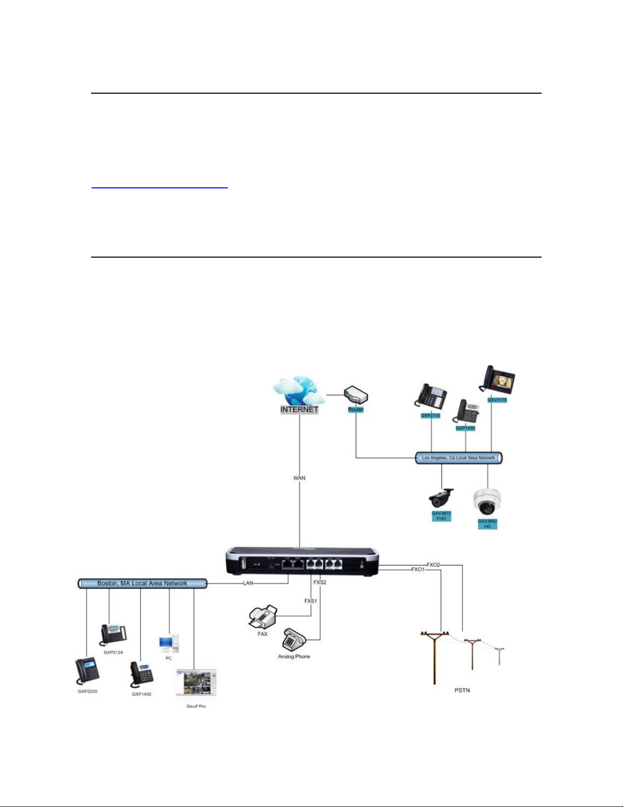
In this setup guide we will be using the U CM6102 whic h has a WAN and LAN interface. The im age
below shows the most t ypical setu p where you ha ve the UCM6100 series WAN port connected to th e
Internet and the LAN side of the UCM6100 series providing DHCP.
We will use this scenario t o setup a Grandstr eam GXP2124 which will be conne cted to the LA N side
of the UCM6100 series. There can also be a network switch connected to the LAN port of the
UCM6100 series so that there may be more than one device connected.
Figure 1: Typical UCM Scenario
4
Page 5

CONNECTING THE UCM6102
QUICK INSTALLATION
Figure 2: Quick Installation Guide for UCM6102
ACCESS UCM6100 SERIES WEB INTERFACE
Accessing the UCM6100 series web interface al low u ser s to m anage us ers and system settings locally as
well as remotely.
To access the web UI, depends on where the user’s computer is connected. If the computer is connected
to the same switch/router that the UCM6100 series WAN port is connected, then browse to the IP
addressed that is displayed on the UCM6100 series LCD. This address is the WAN IP. If the computer is
connected to the LAN side of the UCM6100 series, then users would browse to the default IP of the
UCM6100 series which is 1 92.1 68.2 .1. If success f ul, the UC M6100 series login p age wil l be dis p layed as
shown below.
Figure 3: Quick Installation Guide – Login Screen
5
Page 6
CREATE USER EXTENSION
CONFIGURE EXTENSION RANGE
First part of conf iguring the UCM6100 series shou ld be about planning for ex pansion. Here are some
questions to think about when setting up extension ranges:
• How many users are in the office?
• Will there be departments within the office?
• Is this office interconnecting with another office?
Once there’s a clear pic ture of how m any users will be at eac h locat ion , how dep artm ents are going to be
segmented and what’s the expected growth of the company, a user can then configure the extension
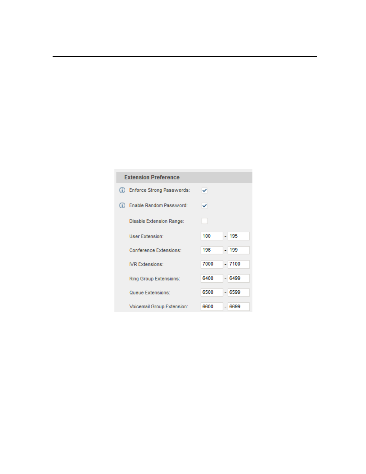
range. Navigate to PBX Internal Options General.
Figure 4: Create User Extension – Extension Range
In the figure above, the user ex tension range is set with a starting extens ion of 100 and ending at 195.
This allows u p to 196 extens ions to as s ign to users. We have also created a c o nf er enc e exte ns io n r an ge
from 196 to 199, which gives 4 c onference bridges. Users can configure an y extension range as they
desire. Here we’ve configured it to use three digit extensions with a leading 1.
Click “Save” at the bott om. Then rem ember to clic k on “Apply Chang es” at the top s o that our extens ion
range will be ready for the next steps.
6
Page 7
BATCH & SINGLE USER CREATION
So now that there’s extension ranges configured, we can now begin creating users to prepare for the
provisioning process . Ther e are t wo methods of cr eating a us er. On e m ethod would be creat ing a s ingle
user. The other method would be creating a batch of users.
TEPS ON ADDING SINGLE USER
S
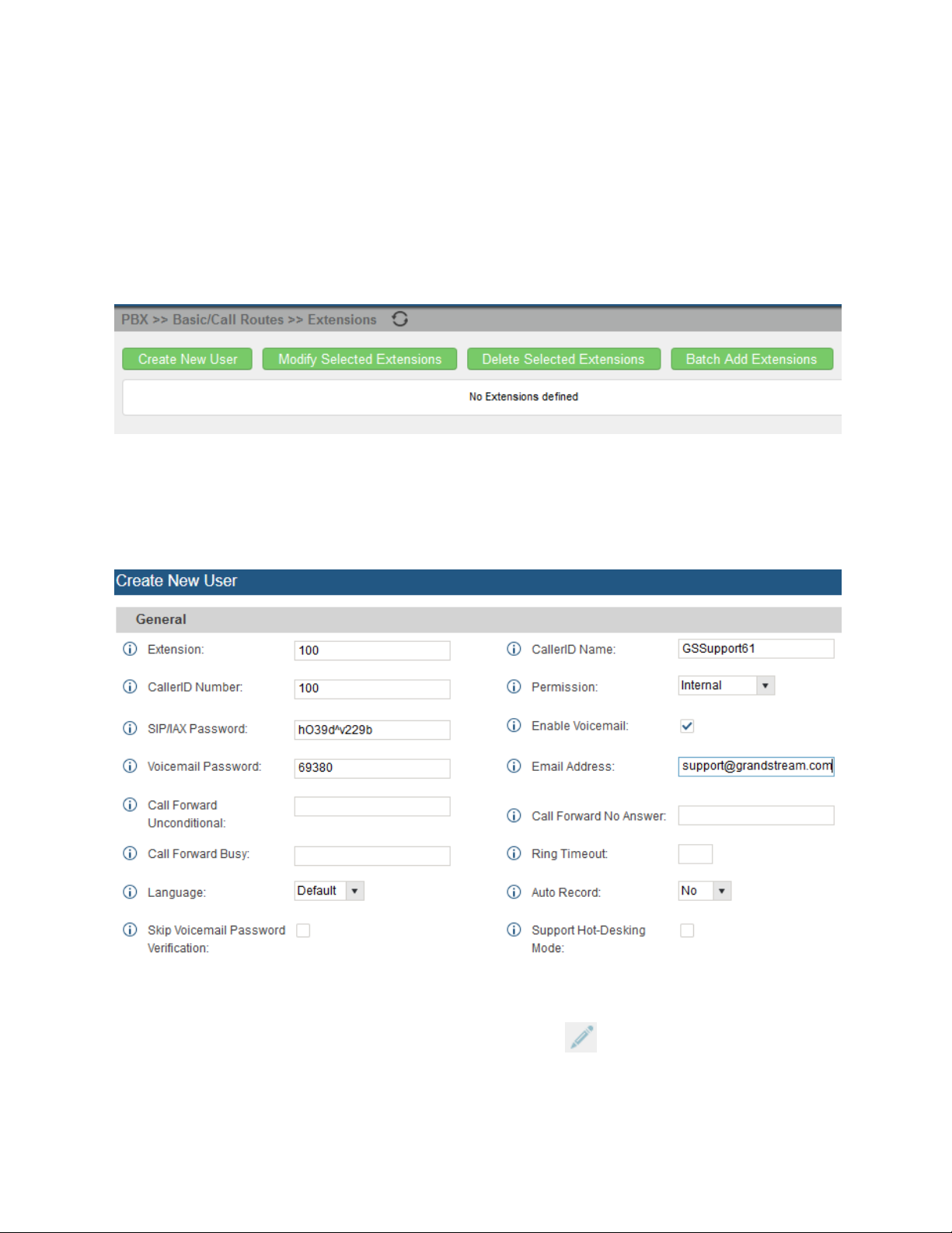
1. Navigate to PBX Basic/Call Routes Extensions. For first time setups users will see “No
Extension defined”.
Figure 5: Create User Extension – Extensions
2. Click on “Create New User”
3. On the “Create New User” screen, users can enter in quite a few options, but they are not required for
this tutorial. Click “Save” at the bottom of the page.
Figure 6: Create User Extension – Create New User
After clicking “Save” the Extensions pag e will disp lay with the single SI P extension tha t was just creat ed.
Here the user has the ability to edit the extensions by clicking the at the right.
7
Page 8

Figure 7: Create User Extension – Created Single User
S
TEPS ON ADDING BATCH OF USERS
1. Navigate to PBX Basic/Call Routes Extensions
2. Click on “Batch Add Extensions”
3. At the “Batch Add Extens io ns” dia log, the user c an sp ecif y the “Start ing Exte nsio n” and the num ber
of extensions to generat e by setting the “Create Num ber”. In this tutorial we will have a starting
extension of 101 and have the UCM6100 series generate 5 extensions with a password random ly
generated. This would create extensions 101, 102, 103, 104 and 105.
Figure 8: Create User Extension – Batch Add User
4. Click “Create Users” at the bottom to ha ve the UCM6100 series generate the extens ions
5. Next, a prompt will app ear as k ing “Are you s ure you want to c re ate users : 101, 102, 103, 104 105”.
Click “OK”.
Figure 9: Create User Extension – Create User Prompt
8
Page 9

At this point the Extensions page should look similar to this:
Figure 10: Create User Extension – Single and Batch Add Extensions Created
For more details on Extension parameters please see the
UCM6100 series User Manual.
9
Page 10

PROVISIONING & ZERO CONFIG
Grandstream SIP Devices can be configured via Web interface as well as via configuration file through
TFTP/HTTP/HTTPS download. All Grandstream SIP devices support a proprietary binary format
configuration file and X ML format configuration file. T he UCM6100 prov ides a Plug and Pla y mechanism
to auto-provision th e Grands tream SIP devices in a zero conf iguration m anner by gen erating XML config
file and having the phone t o download it. This allows users to f inish the installation with ease and start
using the SIP devices in a managed way.
To provision a phone, three steps are involved, i.e., discovery, assignment and provisioning. The
UCM6100
creates XML config file to the detected/assigned Grandstream device and accomplishes the following
configurations on the device after the provisioning:
• A UCM6100 extension will be assigned and registered on the phone.
• SIP-related network settings such as "NAT traversal" and "Use Random Port" are configured o n
the phone.
• Call settings such as "Dial Plan" and "Auto Answer".
• LDAP client configurations will be set up automatically on the phone to use the default LDAP
directory
• generated in the UCM6100 LDAP server.
This section explains how zero config works on the UCM6100. The settings for this feature can be
accessed via Web GUI->PBX->Basic/Call Routes->Zero Config.
AUTO DISCOVERING
When referring back to our typical scenario in the beginning of this tutorial, we know that there is a
GXP2124 connected to the LAN side of the UCM6100 series. T he UCM6100 series LAN interface has
DHCP enabled and has ass igned the GXP2 124 with an IP address. By default the IP ass igned would be
within the 192.168.2.X range. When the UCM6100 series offers an IP address to the phone it also off ers
DHCP Option 66, whic h provides the ph one with a conf ig server path tha t points to the UCM6100 series.
All of Grandstream VoIP devices have Opti on 66 turned on by default a nd this is how the GXP 2124 was
discovered by the UCM6102.
Upon being discovere d, the GXP2124 will provide details about its MAC, IP Address, Version(Firmware),
Vendor, Model, Connection Status and Create Config.
By navigating to PBXBasic/Call RoutesZero Config, a user will be able to see the discovered
device(s).
Figure 11: Provisioning with Zero Config – Auto Discovery
10
Page 11

EXTENSION ASSIGNMENT
In the Auto Provision settings, users have the option to enable “Automatically Assign Extension”. If
enabled, an extension will be cr eated and as signed to the new d evice detect ed. This is a gr eat featur e if
specific extension assignment isn’t required, but for our setup we’ll work on manually assigning an
extension to a discovered device.
Navigate to PBXBasic/Call RoutesZero Config and click on the for the discovered device.
The next screen pro vides detai ls of the de vice and als o allows a user to as sign an exte nsion. S ince our
GXP2124 is a 4 line phone, the UCM6100 series gives us the option to assign 4 extensions to the phone.
Figure 12: Provisioning with Zero Config – Extension Assignment
Click on the Account 1 and select the desired extension, then click “Save”. No w the Zero Config page
displays the device with an extensio n assig ne d to it on Account 1.
Figure 13: Provisioning with Zero Config – Manually Assigned Extension
After assigning an ex tension, the phone m ust be rebooted in order t o pick up the configura tion file from
the UCM6100 series. During this process, the phone will bootup, request for conf ig file,download the
config file, then reboot once more in order to apply the changes.
After the phone is com pletely booted, Navigate to PBXBasic/Cal l RoutesExtensio ns page to see the
extension status. The SIP status will show a green circle for a successful registration.
Figure 14: Provisioning with Zero Config – Extension Status
11
Page 12

CONFERENCE BRIDGE
The UCM6100 supports conference bridge allowing multiple bridges used at the same time:
• UCM6102/6104 suppor ts up to 3 conf erence bridges allowing up to 25 simultan eous PST N or IP
participants.
• UCM6108/6116 supports up to 6 conference bridges allowing up to 32 simultan eous PSTN or IP
participants.
The conference bridge configurations can be accessed under Web GUI->PBX->Call Features>Conference. In this page, users could create, edit, view, invite, manage the participants and delete
conference bridges. T he c o nf er enc e brid ge s t atus a nd c onf erenc e c al l rec ord ings (if r ec ording is en abled)
will be displayed in this web page as well.
HOW TO SETUP A CONFERENCE BRIDGE
1. Click on “Create New Conference Room”
2. At the “Create New Co nference R oom ” screen, the Ex tension is autom aticall y populated sinc e the
extension range is in effect. Users can assign another number that is within the Conference
Extension range
3. Next, uncheck the option “ Public Mode”. This will m ake the password options a vailable. Enter a
numeric password f or an admin as well as the regular user pass word. In this example, the user
enters 511511 as the user password and 510510 as the admin password.
Figure 15: Conference Bridge – Create New Conference Room
12
Page 13

4. Click “Save” at the bottom then “Apply Changes” at the top.
We should now have a conference room created and the status page will display the following:
Figure 16: Conference Bridge – Create New Conference Room
With the phone that was re gistered to t he UCM 6100 series, dial the conference r oom extension. For th is
example we will d ial 196. The user will hear a prom pt for the conference password. Depen ding on the
user, the regular password or admin password can be entered.
During a conference call, the admin can login to the UCM6100 series and view the conference room
status. This provides t he adm in with d etails o n wh ich c onfer ence room is ac tive, who the p artici pants ar e
and the conference call current duration.
Besides status inf orm ation, the a dm in has a sev eral c onf erence m anagement tools. By cl ick ing the
button, the admin c an invite oth er users to the conf erence. C licking will kick the selected us er from
the conference. When clicking or button the admin will mute/unmute the specific user.
Figure 17: Conference Bridge – Conference In Progress
For more options and features for the conference room, please see the
UCM6100 series User Manual
13
Page 14

IVR
CONFIGURE IVR
IVR configurations can be accessed under the UCM6100 Web GUI->PBX->Call Features->IVR. Users
could create, edit, view and delete an IVR.
• Click on "Create New IVR" to add a new IVR.
• Click on to edit the IVR configuration.
• Click on to delete the IVR.
Figure 18: IVR – Manage IVR
CREATE NEW IVR
1. Click on “Create New IVR”
2. Enter a Name for the IVR. This is used for referencing purposes. In this example the user will
create “OfficeHours2”
3. “Extension” is populated automatically by the extensi on range that was crea ted in the beginni ng of
the tutorial. A user may choose another IVR extension within the range if desired.
4. Enable “Dial Other Extensions” to allow ca llers who r each the I VR to dial a direct int ernal extens ion
without having to go through voice prompts.
5. “Welcome Prompt” is the recording t hat will be played when a caller reaches the IVR. User s can
click on the “Prompt” link next to the dropdown box to configure a welcome prompt.
14
Page 15
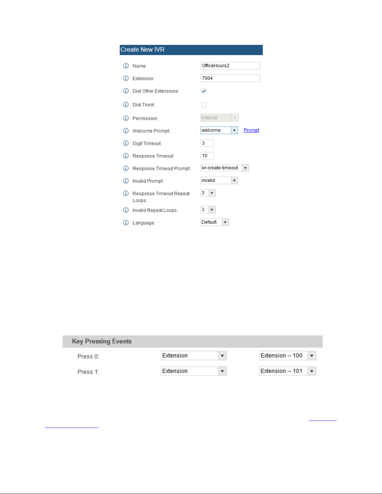
Figure 19: IVR – Create New IVR
6. The next section o n configuring an I VR would be the K ey Pressing Events. Users can direct c alls
based on a callers selec tio n. F or ex ample, a caller reaches the I VR a nd the Welcome Prompt pla ys,
“Thank you for calling Grandstream Networks. For support, please dial 0. For Sales, please dial 1.”
Click on the drop do wn box for the first event, whic h is “ Pres s 0” and s el ect Exte ns ion. An oth er drop
down box will appear and the user can then select an ex tension from the list. For this exam ple, the
user selects Extension 100.
7. For Key Pressing Event “P ress 1” click on the drop down box and select Extension. User selects
Extension 101. Besides from Extension as a Key Pressing Event, the user can select Voicemail,
Conference Room, V oicemail Group, IVR, Ring Group and many more.
Figure 20: IVR – Key Pressing Events
8. Click “Save” at the bottom and then click on “Apply Changes” at the top.
To f ind out more opti ons and par ameter desc riptions in reg ards to th e IVR, pleas e refer to th e
series User Manual
.
UCM6100
15
Page 16

TRUNKS
ANALOG TRUNKS
Go to Web GUI->PBX->Basic/Call Routes->Analog Trunks to add and edit analog trunks.
• Click on "Create New Analog Trunk" to add a new analog trunk.
• Click on to edit the analog trunk.
• Click on to delete the analog trunk.
The UCM6100 series has built in FXO ports which a llo ws i t to pu ll in PSTN lines and provi de ana lo g trunk
service. For this example, we will configure an analog line that is connected to FXO1.
ETUP ANALOG TRUNK
S
1. Click on “Create New Analog Trunk”
2. For “Channels” select 1
3. Trunk Name is set to “Analog1”
4. “Caller ID Scheme” is set for “Bellcore/Telcordia”. Depending on the provider, users can select
other schemes
5. “Tone Co untry” is set to “United States of America (USA)” since this tut orial is setup in the North
American region. Users can click the dropdown box to select an option more suited for their region
6. Click “Save” and then click on “Apply Changes” at the top
Figure 21: Analog Trunks – Create New Analog Trunk
16
Page 17

Note: If there are repor ts of calls bei ng dro pped a nd lines are n ot disc onnec ting properl y, this could mean
that there are line sett ings m ismatched. T he UCM6100 series offers an auto detect feature that tests the
line and provides the best poss ible settings. T his option is called “PST N Detection” whic h can be foun d
under the Analog trunk configuration page.
VOIP TRUNKS
VoIP trunks can be configured under Web GUI->PBX->Basic /Ca ll Rout es ->VoIP Trunks. Once created,
the VoIP trunks will be listed with Provider Name, Type, Hostname/IP, Username and Options to
edit/detect the trunk.
• Click on "Create New SIP/IAX Trunk" to add a new VoIP trunk.
• Click on to configure detailed parameters for the VoIP trunk.
• Click on to configure Direct Outward Dialing (DOD) for the SIP Trunk
• Click on to start LDAP Sync
• Click on to delete the VoIP trunk.
There are 4 different t ype of VoIP trunks that can be configured. The types are Pe ered/Registered SI P
trunk or Peered/Reg istered IAX trunk. This tutor ial will demonstrate how to c onfigure a SIP Registered
Trunk.
ETUP VOIP TRUNK
S
1. Click on “Create New SIP/IAX Trunk”
2. Click the dropdown box for Type and select “Register SIP Trunk”
3. Enter a name for “Provider Name” e.g., GSTrunk
4. Configure the IP address or URL of the VoIP providers server as the “Host Name” e.g.,
sip.grandstream.com
5. Input the username to authenticate with the VoIP provider as the “Username” e.g, 6266389172
6. Enter password for username to authenticate with VoIP provider server
7. Enter the AuthID. This is the SI P service subs crib er’s ID used for authent icati on. If not conf igured,
the CallerID will be used for authentication.
8. Enter an outbound proxy if the provider requires one
9. Click “Save” and then “Apply Changes” at the top
17
Page 18

Figure 22: VoIP Trunks – Create New Register SIP Trunk
After creating the SIP trunk, us ers can click the on the right of the VoIP trunk for more conf iguration
options.
Figure 23: VoIP Trunks – Edit V oIP Trunk
To verify if the SIP trunk is registered, the user may navigate to Web UI->Status.
Figure 24: Status – Trunks
18
Page 19

CALL ROUTES
OUTBOUND ROUTES
In the UCM6100, an outgoing c alling rule pairs an ex tension patter n with a trunk used to dial the patter n.
This allows different patterns to be dialed through different trunks (e.g., "Local" 7-digit dials through a
FXO while "Long distanc e" 10-digit dials through a low-cost SIP trunk) . Users can also set up a failov er
trunk to be used when the primary trunk fails.
Go to Web GUI->PBX->Basic/Call Routes->Outbound Routes to add and edit outbound rules.
• Click on "Create New Outbound Rule" to add a new outbound route.
• Click on to edit the outbound route.
• Click on to delete the outbound route.
• Click on to move the outb ound route up/down to arrange the pr iority of the outboun d
rule. The outbound ru le listed o n the t op has hig her priorit y. W hen the dial ing patt ern matc hes two or
more outbound rules (f or example, th e sam e pattern is c onfigured for 2 differ ent trunks ; or dialing out
1000 matches patter n 1xxx f or trunk 1 and pattern 10 0x for trunk 2), the one lis ted on the top will be
used.
OW TO CONFIGURE AN OUTBOUND ROUTE
H
1. Click “Create New Outbound Rule”
2. Configure the name of the Calling Rule. For example, ‘Local’, ‘LongDistance’ and etc.
3. Create a dial Pattern. For 7 digit dialing (Local) the pattern will look like this: XXXXXXX
This means that an y 7 digits will use th is route. F or 10 di git dialin g the patter n woul d look lik e this:
NXXNXXXXXX. If a ‘1’ is required before dialing out, the dial patter can be configured in this
manner: 1NXXNXXXXXX.
In this example, the dial pattern is going to be created for local 7 digit dialing so the pattern is
XXXXXX
4. Next, set a “Privilege Level”. There are 4 Pr ivilege Levels; Interna l, Local, National, Inter national.
Internal is the lowest level of security where as international is the highest level of security.
The way that Privilege Levels are used could be thought of as door lock s. Extens ions are grante d
with “Permissions” that can be seen as keys. If an Extension is configured with an Internal
permission, it CANNOT access an outbound route with a Privilege level of Local, National and
International. A user c onfigured with National p ermission can access routes th at have a Privilege
Level of Internal, Local, National, but not Inter nat ion al.
5. The pattern that was configured is a 7 digit dialing pattern. For “Use Trunk” select the Analog Trunk
or select the desir ed trunk for this particular dial p attern. For long distance calls , it may be cost
effective to route the calls to SIP trunk versus going through a local PSTN line.
6. Click “Save” and then click on “Apply Changes” at the top.
19
Page 20

Figure 25: Routes – Create Outbound Route
INBOUND ROUTES
In the UCM6100, an incoming calling rule allows for various inbound destinations. Users can route
inbound calls by DI D, to Extension , Voicemail, Conf erence Room, Queue, Ring Group, Page, Voicemail
Group, FAX, DISA or IVR. These inbound routes can also be triggered based on a time condition as well.
Inbound routes can be configured via Web GUI->PBX->Basic/C a ll Rout es->Inbound Routes.
• Click on "Create New Inbound Rule" to add a new inbound route.
• Click on "DID Features" to configure DID features for the inbound route.
• Click on "Blacklist" to configure blacklist for all inbound routes.
• Click on to edit the inbound route.
• Click on to delete the inbound route.
This section of the tutorial will pro vide instruct ions on ho w to setu p an i nbound ro ute for a R egist ered SIP
Trunk. Inbound calls into this SIP trunk will have a default destination as well as a time conditioned
destination.
20
Page 21

SETUP INBOUND ROUTE
1. Click on “Create New Inbound Rule”
2. For “Trunks” select the SIP trunk that has been configured. (e.g. GS Trunk)
3. The DID pattern can be com posed of two par ts, divided b y a ‘/’ charac ter. The f irst part is us ed to
specify the dialed n umber and the s econd p art is use d to spec ify the caller I D, which is optiona l. If
caller ID section is ent ered it means onl y the extensio n with the specific c aller ID is allo wed to call
into this trunk.
4. “Privilege level” can be left as Internal
5. Click the dropdown box for “Default Destination” and select IVR. Then select the IVR extension.
6. Next, click on “Click to add Time Condition”.
7. Enter a “Start Time” of 8am, “End Time” of 6pm.
8. Next select By Week for “Date” and select Monday-Friday.
9. For “Destination” select Extension and choose an extension number.
Figure 26: Routes – Create Inbound Route
When a call is received on t his SI P trunk during the hours of 8am to 6pm it will b e routed t o ex tens i on 1 00.
All calls outside of this condition will be routed to the IVR extension 7004.
If there are any questions or concerns, please feel free to get in contact with Grandstream Networks support by
calling (617) 566-9300 or create a support ticket by clicking this
link.
21
 Loading...