

Page 1
GRAND SOLAR INC.
BLAZING TUBES
INTEGRAL COLLECTOR STORAGE WATER HEATER
INSTALLATION, OPERATION AND MAINTENANCE MANUAL
Page 2

BLAZING TUBES INTEGRAL COLLECTOR
STORAGE WATER HEATER
INSTALLATION, OPERATION AND MAINTE-
NANCE MANUAL
The Blazing Tubes domestic solar water heating system has gone through an extensive
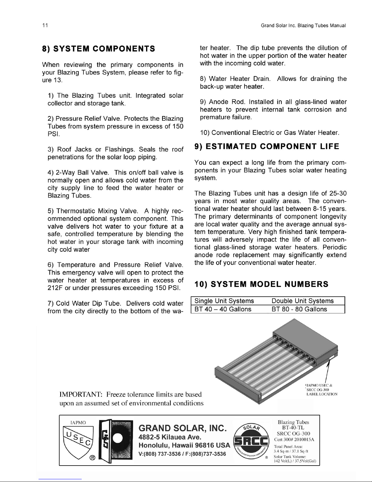
design, technical and performance review by the Solar Rating & Certification Corporation (SRCC). The installation of your Blazing Tubes system is intended to be executed
by properly licensed and experienced professional contractors in accordance with
SRCC Standard OG-300, "Operating Guidelines and Minimum Standards For Certifying", and must conform to applicable federal, state and local regulations, codes, ordinances and standards governing the installation of solar water heating systems.
The solar energy system described by this manual, when properly installed and maintained, meets the minimum standards established by the SRCC. This certification does
not imply endorsement or warranty of this product by the SRCC.
OG-300 system certification is granted to Grand Solar by the SRCC. It may not be used
for any commercial purpose without the prior written consent of Grand Solar. Grand Solar must approve any deviation from the materials and methods described in this manual in writing.
Blazing Tubes units may be safely installed in areas within the continental United States
that experience mild winter climates.
Because Blazing Tubes unit has superior heat conservation characteristics it may be
safely installed wherever mild winters are the norm. However geographic areas, which
experience continuous hard freezes, are inappropriate for Blazing Tubes installations.
Do not install if local temperatures ever fall to:
10ºF / -12˚C for 6 consecutive hours, or
20ºF / -7˚C for 18 consecutive hours
Grand Solar prohibits the installation of Blazing Tubes systems in any areas susceptible
to temperatures lower than those stated above. Warranty coverage is voided in the
event this prohibition is ignored.
Page 3

TABLE OF CONTENTS
PREFACE ........................................................................................................................................... 1
1) INTRODUCTION ............................................................................................................................. 1
2) SYSTEM DESCRIPTION AND OPERATIONAL PRINCIPLE.......................................................... 2
3) INSTALLATION REQUIREMENTS - GENERAL - .......................................................................... 2
A. Permits .................................................................................................................................... 2
B. Code ........................................................................................................................................ 2
C. Structural & Shading Considerations ....................................................................................... 2
D. Roof and Site Inspection.......................................................................................................... 2
E. Confirmation of Installation Site ............................................................................................... 2
4) INSTALLATION REQUIREMENTS - SPECIFIC - ........................................................................... 3
A. Location, Orientation and Tilt ................................................................................................... 3
B. Blazing tubes Roof Mounting Procedures, Materials and Methods........................................... 3
C. Ground Mounting..................................................................................................................... 5
D. System Plumbing..................................................................................................................... 5
E. Plumbing Two Blazing Tubes................................................................................................... 8
F. Insulation Procedures .............................................................................................................. 8
5) SYSTEM START UP PROCEDURES ............................................................................................. 9
6) OVERHEAT PROTECTION ...........................................................................................................10
7) ROUTINE MAINTENANCE PROCEDURES ..................................................................................10
8) SYSTEM COMPONENTS ..............................................................................................................11
9) ESTIMATED COMPONENT LIFE ..................................................................................................11
10) SYSTEM MODEL NUMBERS ......................................................................................................11
Page 4
1 Grand Solar Inc. Blazing Tubes Manual
PREFACE
Let us first offer two words of grateful appreciation. Thank You! We sincerely appreciate your
business. Grand Solar also wishes to say thank you for “going solar.” Solar water heating systems reduce our nation’s dependence on polluting fossil fuels, minimize the greenhouse gas
emissions associated with conventional water heating and, very importantly, lower your monthly
utility costs.
Your Blazing Tubes system has been designed to meet exacting SRCC certification requirements. The specific components found in your system have been selected by your contractor
for their proven reliability, longevity and performance.
1) INTRODUCTION
Solar water heating systems are climate and site specific appliances. Different types of solar
systems are installed around the world based upon local and regional weather and water quality
conditions. System performance varies as a function of household hot water load, including
daily showers and baths, laundry and kitchen uses, local ground water and ambient air temperatures, your home’s roof pitch and orientation and, of course, the seasonal intensity of solar radiation. These variables, some of which change from home to home in the same neighborhood,
will determine how much energy and money your Blazing Tubes system will save on an annual
basis.
This manual is intended as a basic solar water heating primer. Our goal is to familiarize you
with the proper installation, operation and maintenance of your Blazing Tubes system. This system is required to be installed by properly licensed solar or plumbing contractors in accordance
with SRCC certification requirements and all applicable national, state and local codes, ordinances and regulations governing solar water heating systems as well as good trade practices.
Failure to follow the procedures and practices described in this manual can void the manufacturer’s warranty for specific component parts.
Page 5
2 Grand Solar Inc. Blazing Tubes Manual
2) SYSTEM DESCRIPTION AND
OPERATIONAL PRINCIPLE
The Blazing Tubes is an integral collector storage system. Systems combine the collector and
storage tank in a single roof-mounted unit. systems, in general, serve as pre-heaters for conventional electric or gas water heaters. In some
parts of the world the Blazing Tubes may serve
as the sole water heater or will be used in conjunction with a tankless, wall-mounted instantaneous gas water heater.
The Blazing Tubes also is referred to as a “passive” system because it does not require mechanical pumps, thermostats, sensors, wiring or
electricity to make hot water. Your Blazing
Tubes will neither freeze nor overheat during
prolonged periods of disuse if installed and maintained in accordance with the instructions contained in this manual.
The inherent simplicity and durability of the Blazing Tubes makes it a popular choice for the continental U.S. Sunbelt or markets outside the U.S.
where persistent hard freezes do not occur.
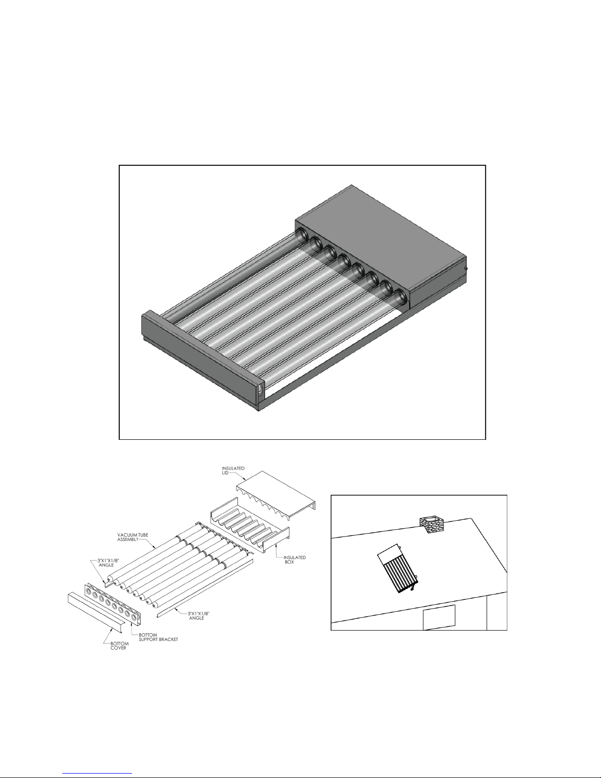
The Blazing Tubes System combines collection
and storage of solar heated water within eight 5”
glass vacuum tubes. Mechanically attached to
these tubes are eight EPDM boots, which house
eight copper heat exchangers, plumbed in series. Insulation surrounds these boots and their
internal heat exchangers, helping conserve the
heat collected by the glass tubes. These tubes
get filled with non-pressurized water, which acts
as a thermal battery for collected solar energy.
Pressurized domestic water flows though the
copper heat exchangers upon demand. Each
Blazing Tubes unit supplies 40 gallons of solar
hot water in a completely passive manner. The
Blazing Tubes system is used in conjunction with
any conventional gas, oil or electric water heater.
3) INSTALLATION
REQUIREMENTS - GENERAL -
A. Permits
The contractor shall obtain all required permits
and approvals.
B. Code
The installation shall conform to all federal, state
and local regulations, codes, ordinances and
standards governing solar water heating system
installations, and the contractor shall adhere to
sound building safety and trade practices. Special consideration must be given to building code
requirements for roof loading and the penetration
of structural members and fire rated assemblies.
C. Structural & Shading Considerations
The Blazing Tubes must be located in a structurally sound area of the roof that will be unshaded
for the majority of the day all year round. Adjacent buildings and trees should be checked for
possible winter shading. An instrument such as
the Solar Pathfinder can be used for solar site
analysis. (Solar Pathfinder can be reached at
605-528-6473).
D. Roof and Site Inspection
Before the installation, the contractor shall inspect the condition of the roof and notify the
homeowner of any existing roof damage or necessary repairs.
E. Confirmation of Installation Site
The homeowner and contractor shall confirm the
location of all roof and ground mounted components in advance of the installation.
Page 6
3 Grand Solar Inc. Blazing Tubes Manual
4) INSTALLATION
REQUIREMENTS - SPECIFIC -
A. Location, Orientation and Tilt
Depending upon the model purchased, single
Blazing Tubes units will weigh between 321 and
597 pounds when filled. DO NOT proceed with
the installation unless the roof can safely support
the unit. Consult your local building code for
structural requirements before beginning the installation.
The thermal performance of the Blazing Tubes is
optimized in the Northern Hemisphere when the
unit is mounted facing True South. Actual performance, however, suffers very little when the
unit is oriented no more than 45º East or West of
True South. The unit should be unshaded for the
middle six hours of each day throughout the
year.
The slope of your roof will have an impact on
thermal performance. We recommend that you
tilt the unit to achieve an angle from horizontal
that is equal to your latitude plus an additional 10
degrees. This tilt angle favors the lower winter
sun when system performance may suffer and
minimizes overheating during the hot summer
months.
To ensure optimal performance the unit must
maintain a minimum angle from horizontal of at
least 10º.
Never mount the Blazing Tubes directly or parallel to a flat roof.
B. Blazing tubes Roof Mounting Procedures, Materials and Methods
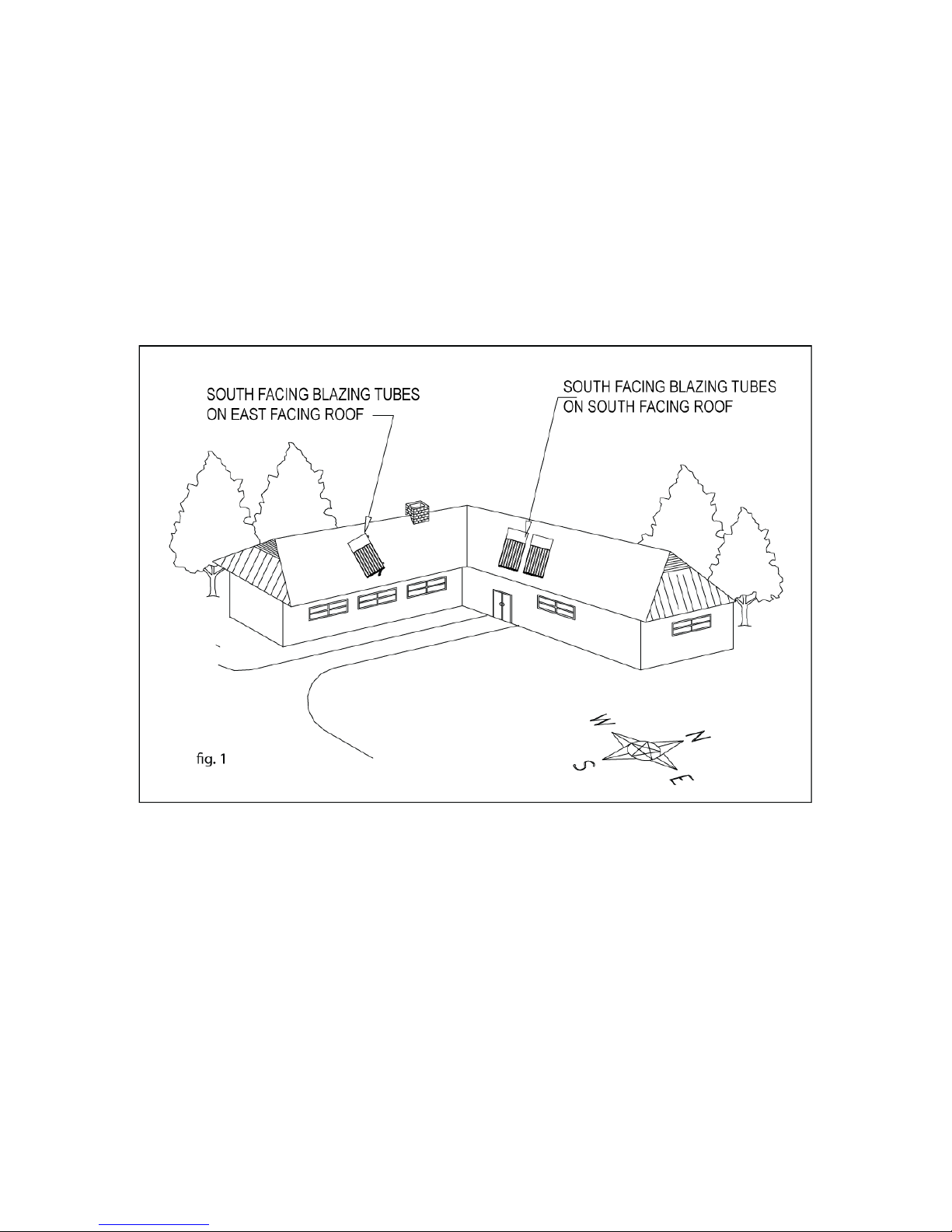
In continental North America it is best to mount
the Blazing Tubes horizontally on a south facing
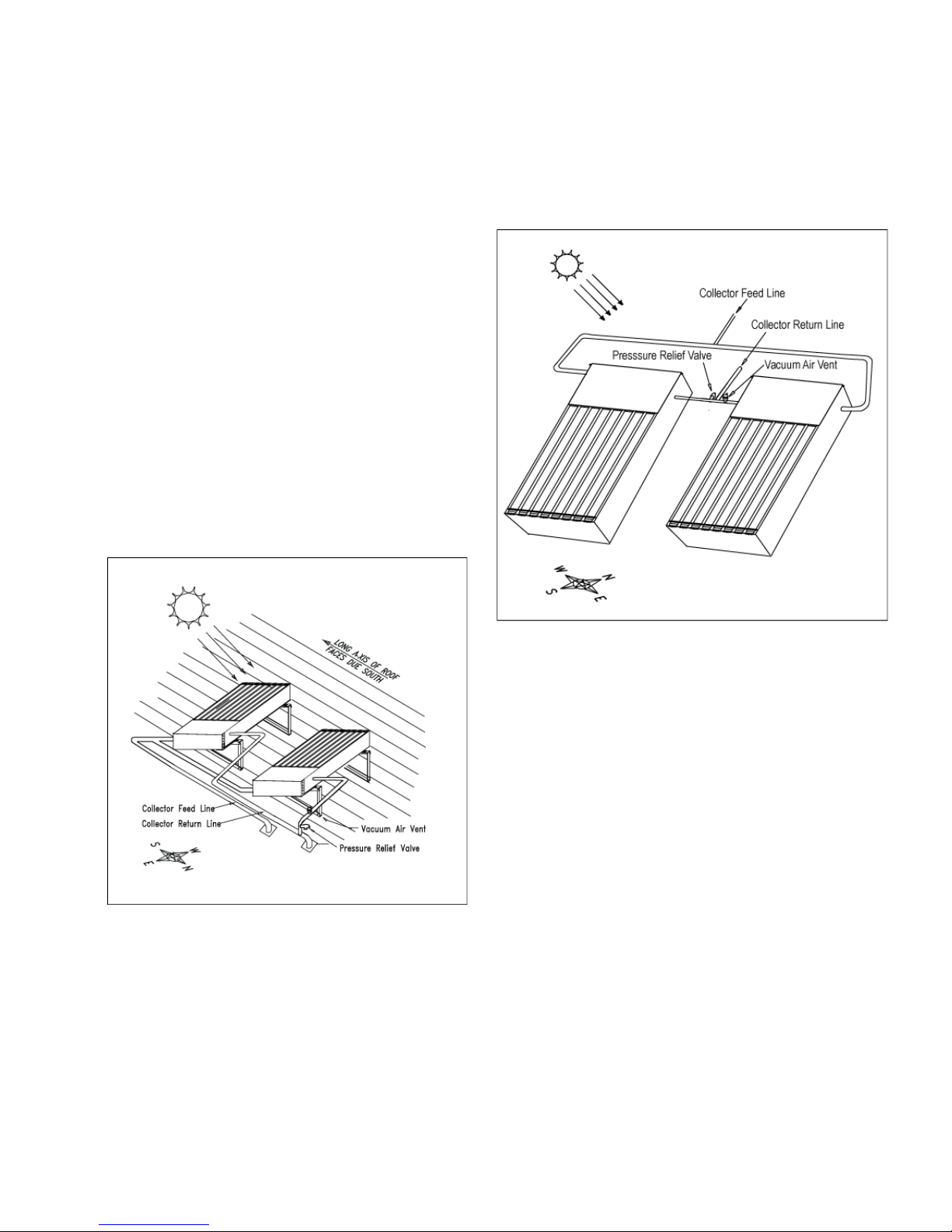
roof (fig 1). If necessary, the unit may be
mounted on an east or west-facing roof, with the
long axis perpendicular to the ridge and eve, and
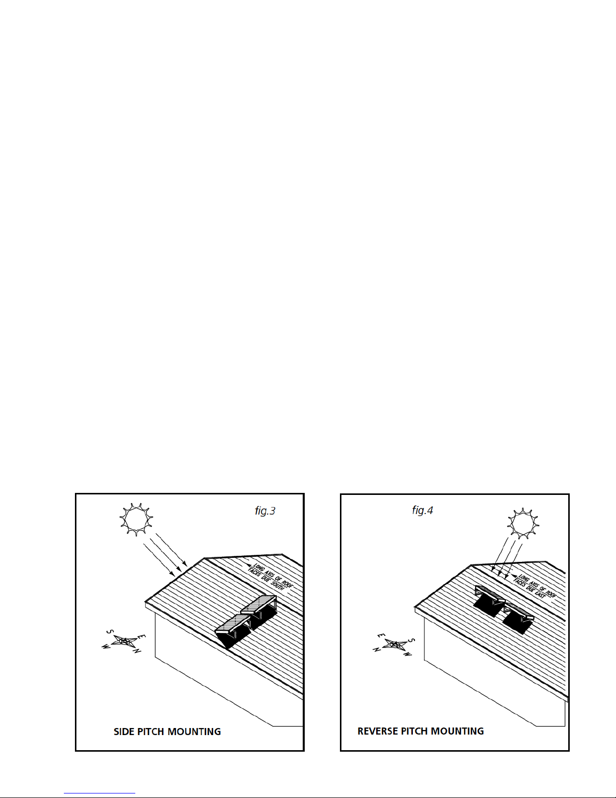
tilted toward the south. In two unit installations on
east or west facing roofs, the Blazing Tubes must
be mounted in a staggered, or “saw tooth”, configuration (See figure 3). For flat roof installations
the unit must maintain a minimum angle from
horizontal of 10˚.
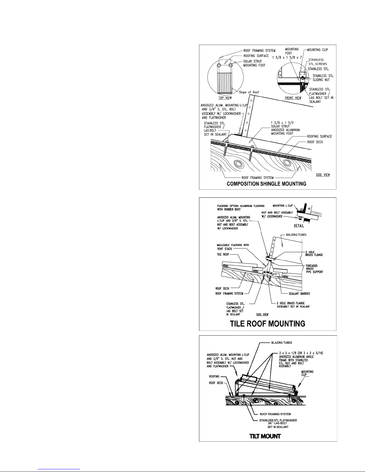
The Blazing Tubes must be mounted in accordance with the materials and methods detailed in
figures 5 to 11. Use integrated Solar Strut anodized aluminum mounting hardware for mounting
the unit.
Secure the Solar Strut mounting hardware directly to the rafters or support cross bracing. Attach the Blazing Tubes to the Solar Strut mounting hardware with anodized aluminum mounting
clips and a stainless steel nut, bolt, lock washer
and flat washer. When the unit is flush mounted
(figure 5) it should be anchored to the roof by no
less than four support footings, two on each side
of the unit.
Page 7
4 Grand Solar Inc. Blazing Tubes Manual
Follow these general principles when mounting
the Blazing Tubes:
B.1 The roof must be rated to safely support the
weight of the unit when filled with water.
B.2 The Blazing Tubes should be mounted as
close to the storage tank as practical in order to
minimize heat loss in the piping runs.
B.3 Grand Solar recommends that the Blazing
Tubes be raised from the roof surface at least
1-1/2” to allow for rainwater and debris to pass
under the unit and for proper ventilation of the
roofing material.
B.4 In selecting mounting hardware and fasteners it is extremely important to avoid galvanic
corrosion resulting from the direct contact of incompatible metals. Use of Grand Solar anodized
aluminum “Solar Strut” mounting hardware and
stainless steel lag or hanger bolts, lock washers
and round washers is recommended. In climates
subject to severe winters or high humidity use of
galvanized fasteners is prohibited.
B.5 Preserving the integrity of the roof membrane is the most important roofing consideration. Ensure that all roof penetrations required to
plumb and mount the solar collector are properly
flashed and sealed in accordance with standard
roofing practices. Tremco “POLYroof” is the recommended elastomer for sealing roof penetrations. Henry Co. 204, 208 or 209 roof mastic or
Dow Corning Glazing Sealant also are approved
sealants.
B.6 If the Blazing Tubes is mounted on a flat roof
or the ground, a Blazing Tubes Tilt Mount Kit is
required (figures 7 and 11). Optimal system performance is achieved by establishing a rack angle from horizontal equal to latitude plus ten degrees
B.7 If the region is subject to hurricane conditions, additional steps may be required to secure
the collector and mounting hardware the
the structural members. In certain areas of the
country, local building codes may require collector wind load testing or prescribe specific mounting procedures. Consult your local building department.
fig. 6
fig. 5
fig. 7
Page 8
5 Grand Solar Inc. Blazing Tubes Manual
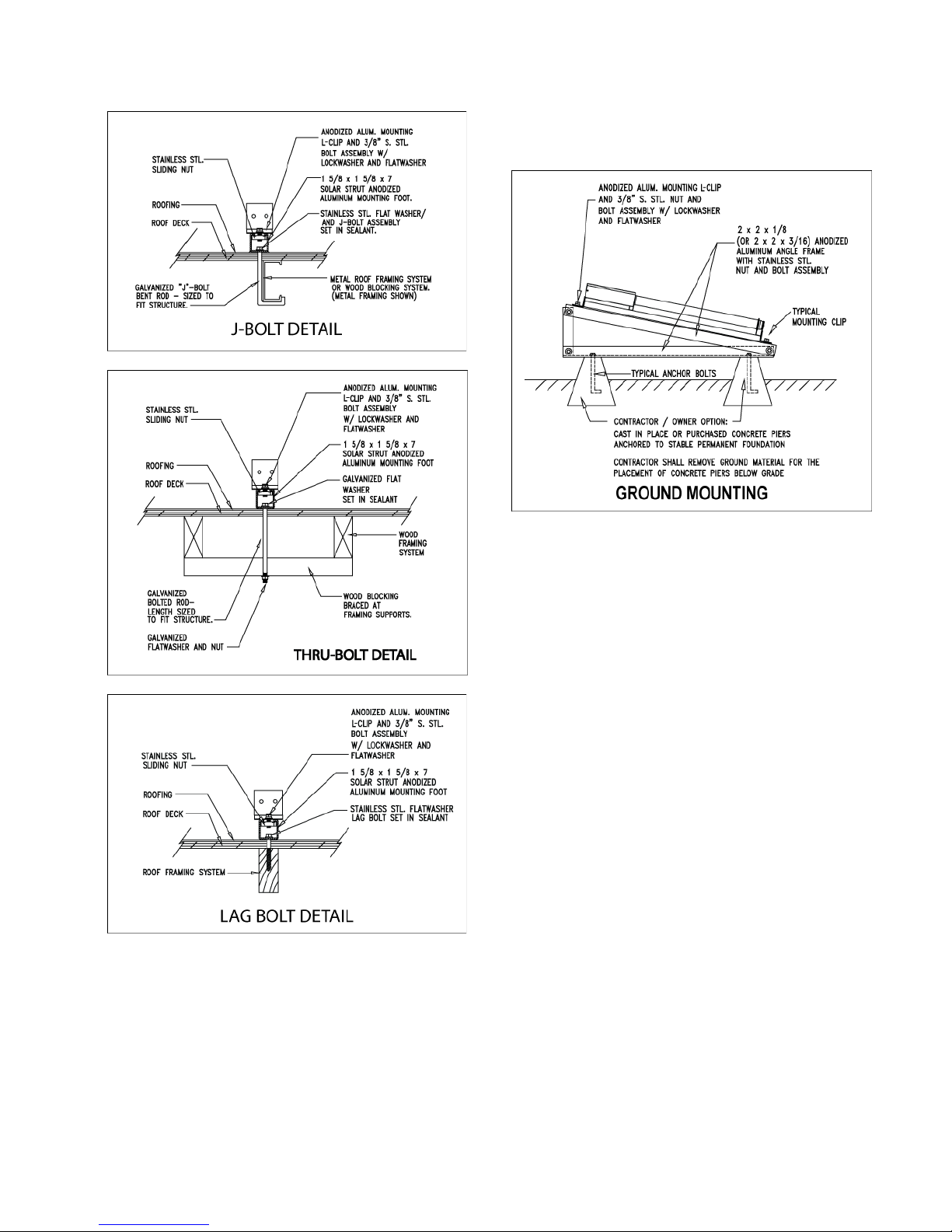
C. Ground Mounting
The Blazing Tubes can be ground mounted.
The unit must have a stable, permanent foundation. This may be either a concrete slab or
four standard concrete piers embedded in the
ground. All bolts and fasteners should be either cast in place or anchored and then epoxyed into the slab or pier. All exposed bolt
threads used to secure the Blazing Tubes
mounting rack must be thoroughly coated with silicone oil to prevent corrosion.
Buried copper tubing must be insulated in accordance with the instructions in section 4F below. All
insulated lines must be buried above the water table and use a clean fill such as a sand layer of 3” to
5” to protect the insulation before backfilling. All
buried material must be properly sealed at all the
seams and butt joints with Rubatex Contact Adhesive or equal. For optimum performance, the insulated lines should be encased in a conduit to protect the material from problems associated with
groundwater or frost.
D. System Plumbing
The Blazing Tubes should be plumbed with all
copper and brass fittings and valves. Use of galvanized fittings is prohibited. Solar loop piping shall
be a minimum 2/4” Type-M copper tubing. 2/4”
Type-L continuous soft copper tubing is recommended for all attic pipe runs. No tubing connections or solder joints should be made in the attic.
Use only lead-free solder (Englehard Silvabrite 100
is recommended). DO NOT use CPVC, PVC or
any type of plastic piping in the solar loop. The
Blazing Tubes can produce temperatures that will
melt plastic piping.
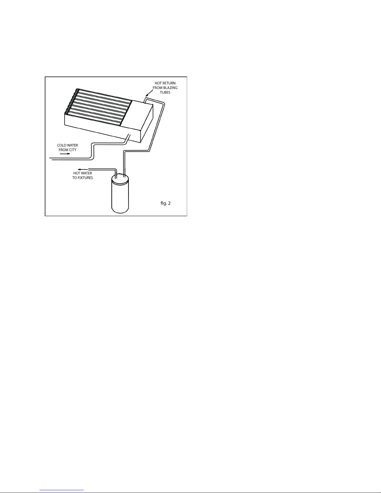
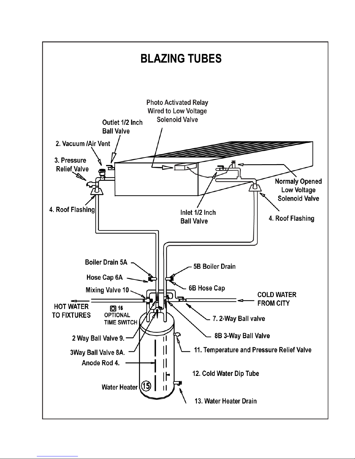
Figure 13 details the plumbing connection between
the Blazing Tubes and the conventional electric or
gas water heater.
The Blazing Tubes units have pressurized water
flowing through their copper heat exchangers. In
fig. 8
fig. 9
fig. 10
fig. 11
Page 9
6 Grand Solar Inc. Blazing Tubes Manual
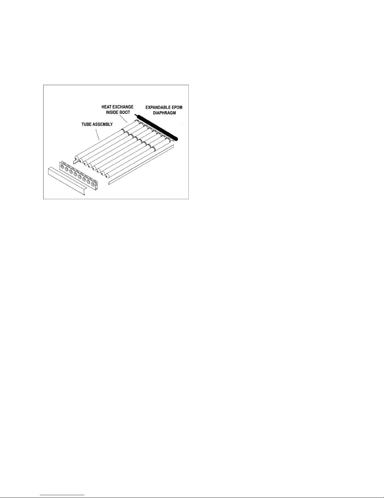
addition the 5” diameter, six foot long, vacuum
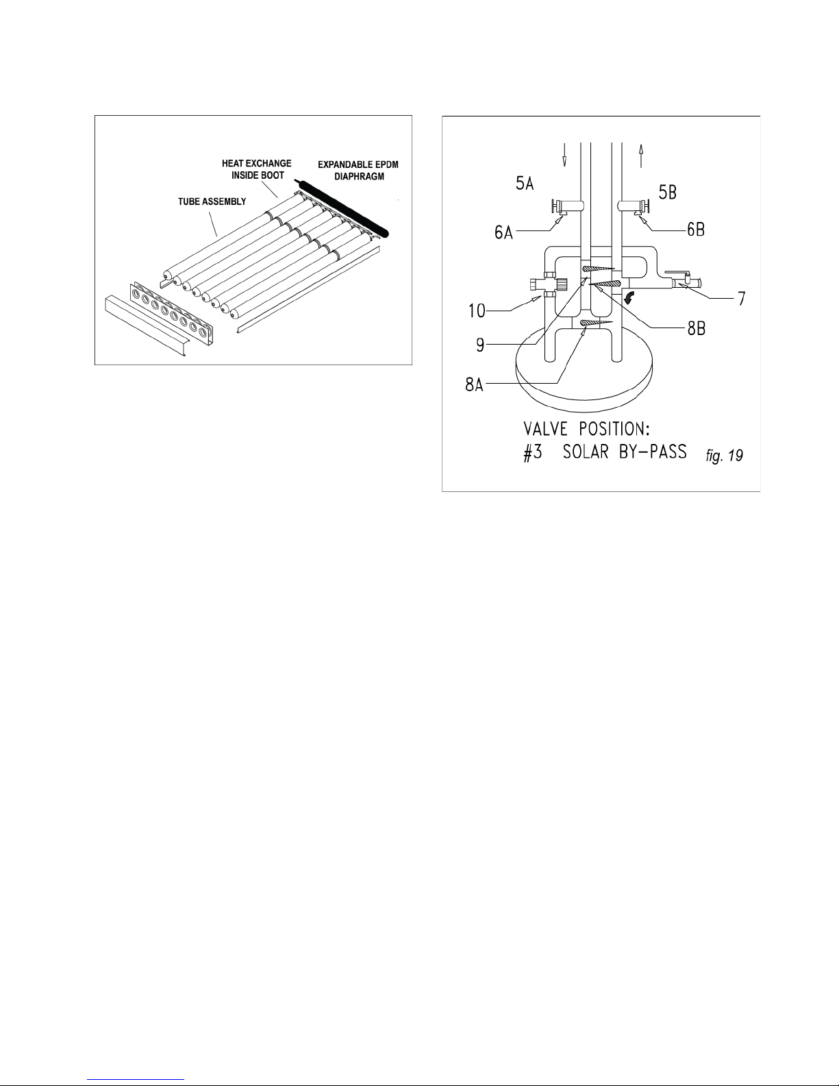
tubes and the attached EPDM boots are permanently filled with non-pressurized water (figure 12).
Each unit is designed with designated water
ports. The two marked “pressurized” are where
the household water flows upon demand by
residents. Two half-inch ball valves are attached to other ports labeled “non-pressurized”.
These valves are to be operated only by
authorized, licensed installers. In addition one
of these non-pressurized valves is equipped
with a solenoid valve, which disallows unauthorized filing during daylight hours. A light
sensitive electronic unit activated the solenoid
to be open only at nighttime.
In plumbing the conventional water heater use only
copper and brass fittings, nipples and unions. Galvanized fittings and dielectric unions may not be
used. All connections should be hard copper. Water heater flex hose connectors use gaskets that
become brittle and compressed over time and may
cause leaks.
Tank plumbing must allow for the isolation of the
water heater from the city cold water supply line by
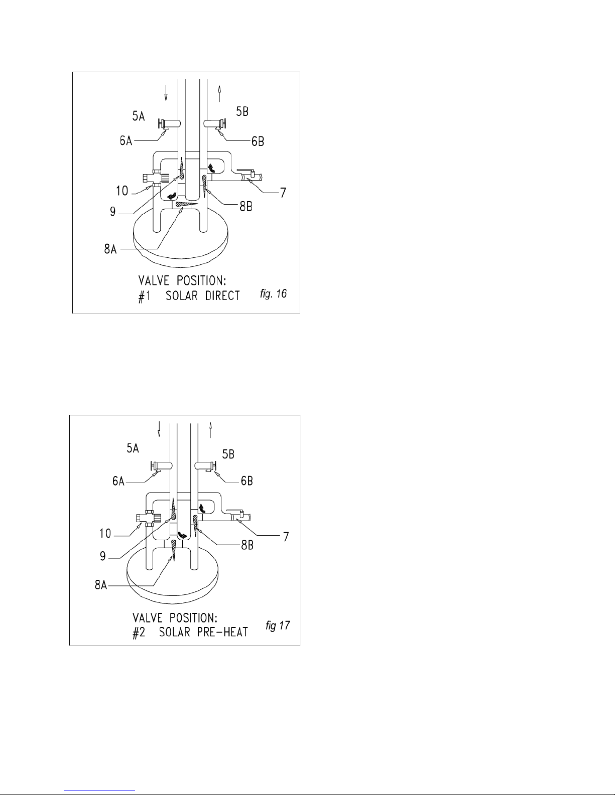
means of an isolating ball valve (figure 13, valve 7).
A high quality thermostatic mixing valve is a required component on all OG-300 certified systems
and should be plumbed in line with brass union
connections for ease of future repair or replacement (figure 13, component 10). The specified
mixing valve shall be the Heatguard model
HGBASE or equal and shall have an operating
range between 95ºF and 140ºF. Set the mixing
valve to operate at 120ºF.
The temperatures generated by the Blazing Tubes
unit will vary throughout the year. In the Northern
Hemisphere the water temperature will be hottest
in the spring and summer months while cooler
temperatures are to be expect from November
through March. On sunny days system temperatures may range between 110ºF to 180ºF depending upon the season and hot water demand. The
mixing valve described above blends the hot and
cold water supplies to deliver hot water to your fixtures at a safe, controlled temperature
Fig. 12
Page 10
7 Grand Solar Inc. Blazing Tubes Manual
Fig. 13
Page 11
8 Grand Solar Inc. Blazing Tubes Manual
WARNING: SCALDING CAN OCCUR
WITHIN FIVE SECONDS WHEN WATER
TEMPERATURES APPROACH 140ºF. THE
MIXING VALVE SHOULD BE ADJUSTED BY
YOUR CONTRACTOR TO PROVIDE WATER
TO YOUR FIXTURES AT NO MORE THAN
120ºF.
All vertical copper piping from the conventional
water heater to the Blazing Tubes unit shall be
supported at each story at maximum intervals
of ten feet (10'). Copper plumbers tape or tube
strap is required to secure the piping. Piping
insulation covering the copper tubing may not
be crimped or compressed by the strapping
material.
E. Plumbing Two Blazing Tubes
When two Blazing Tubes are plumbed together
in a single system they must be plumbed in
parallel in accordance with figures 14 and 15.
F. Insulation Procedures
Proper insulation of the copper tubing to and
from the roof prevents heat loss and provides
freeze protection. The 3/4” feed and return
lines must be covered with pipe insulation of a
minimum 3/4” wall thickness (specified as 7/8”
X 3/4” flexible elastomeric thermal insulation,
Rubatex “Insultube” or equal). A 1” wall thickness is highly recommended. All exposed pipe
insulation must be coated with two coats of an
acrylic water based paint, such as Rubatex
Protective Coating or equal. The paint protects
the insulation from UV degradation, including
cracking and shrinkage, and also provides moisture vapor protection. Inspect the insulation for
cracks and signs of shrinkage every three to five
years. Repaint and repair as necessary.
The 3/4”cold water supply line to the conventional
water heater must be insulated with a minimum
1/2” thick elastomeric thermal insulation (specified
as 7/8” X 1/2” Rubatex “Insultube” or equal) to a
minimum distance of five feet (5') back from the
storage tank, or to the wall if closer than 5'. The
overall performance of the water heating system is
enhanced if the hot water supply lines to all the fixtures are well insulated. The insulation wall thickness may vary between 1/2” to 3/4” depending
upon the local climate. The thicker the insulation
wall the better the heat retention in the piping. If
the Blazing Tubes is installed in new construction,
all exposed hot water service piping in the home
should be well insulated.
The outside and top of the conventional electric or
gas heater also must be insulated with a water
heater insulation jacket. The combined R-Value, or
insulation value, of the water heater and insulation
jacket should be no less than R-17. A foil-faced
bubble-pack insulation material as manufactured
by Reflectix, or equal, is recommended.
fig. 14
fig. 15
Page 12
9 Grand Solar Inc. Blazing Tubes Manual
An air gap between the tank jacket and the insulation material should be created. First apply
three strips of the material around the complete
tank circumference near the top, middle and
bottom of the heater. Then attach the insulation blanket to the strips.
Thoroughly insulate the top of the water heater.
Fit the insulation snuggly around the brass nipples or unions and temperature and pressure
relief valve on the top of the water heater. If
you have an electric water heater, cut two windows in the insulation around the access plates
covering the upper and lower thermostats and
heating elements.
Insulate the area over the assess plates, but make
sure that these areas always remain accessible for
service or repair as necessary.
If the Blazing Tubes is installed in a new home,
Grand Solar specifies that the conventional water
heater have a minimum insulation value of R-20.
The total insulation value of the water heater and
the insulation jacket shall be no less than R-25.
The conventional water heater should not sit directly on the concrete slab or floor. The heater
should be placed on a well-insulated pad with a
minimum insulation value of R-10. A 2” polystyrene
insulation pad such as manufactured by Frost King
is recommended.
5) SYSTEM START UP
PROCEDURES
A. Once the Blazing Tubes is mounted and
plumbed in accordance with the drawings and
specifications in this manual the professional installer should:
Open the main cold water supply to the hot water
system. Simultaneously open any hot water fixture
in the home. This will send the water pressure up
to the roof, filling the heat exchanger first, and then
filling the conventional heater. After completion of
the this phase of the start up, close the hot water
fixture, but leave the cold water supply open.
Now the installer can return to the roof and fill the
“non-pressurized” vacuum tubes/boot volumes.
This procedure must be done before or after sunlight electronically closes the solenoid valve (which
prohibits cold fill during hot daylight hours)
With the solenoid open, water pressure is available
to fill the tubes. Open the two half inch ball valves
at each end of the unit, first the outlet than the inlet;
water will fill the tubes in parallel. Once the tubes
are full, excess water will flow out of the “outlet”
ball valve. Immediately shut the “inlet” ball valve,
which will cause water to stop flowing out of the
“outlet” valve. Finally shut the “outlet” valve and the
filling process is complete. An internal diaphragm
(see fig 18) will allow the water thermal expansion,
which will occur each heating cycle.
Page 13
10 Grand Solar Inc. Blazing Tubes Manual
If you have an electric water heater DO NOT
turn on the electricity to the heater until the
tank is completely filled.
Make sure the tank is completely filled by opening and running a hot water fixture in the home,
or by opening the pressure and temperature
relief valve if located on the top of the water
heater (Note: on some water heaters the temperature and pressure relief valve is located on
the side of the tank near the top). It only takes 8
seconds to destroy the heating elements in an
electric water heater if they are not completely
submerged when the tank is first energized. Be
careful.
A properly licensed contractor must make the
final electrical or gas connection to the conventional water heater.
The thermostat on the electric or gas water
heater should be set no higher than 120 degrees. Use the “low” or “warm” setting if the
thermostat is not calibrated in degrees.
6) OVERHEAT PROTECTION
The Blazing Tubes unit is designed to efficiently
capture sunlight and heat water within an appropriate temperature range for domestic uses.
Overheating is normally never an issue due to
the ratio of solar interception area to water volume. Therefore, high pressure and high temperatures (above 200˚F) are avoided. However,
for ultimate safety each unit has a temperature
and preassure relive valve attached.
7) ROUTINE MAINTENANCE
PROCEDURES
A. Make sure that the Blazing Tubes glass stays
clean. Hose off any caked on dirt or dust and then
clean the glass with Windex or a household glass
cleaner and a soft cloth.
B. Check the exterior exposed pipe insulation annually. Repaint as necessary to prevent cracking
and shrinkage. Repair any exposed areas immediately.
C. In the unusual instance of glass tube breakage,
the glass tube should be replaced immediately.
Contact your installation contractor.
D. The Blazing Tubes is capable of generating very
high temperatures in some climates for eight to ten
months a year. If the water temperature in your
back-up heater is consistently in the range of 140º160ºF, you may want to change the magnesium
anode rod in your back-up water heater every five
years. This “sacrificial anode” is installed in the
heater to prevent internal corrosion and premature
tank failure. Internal corrosion accelerates at
higher tank temperatures. By replacing the anode
rod every five years the life of the back-up water
heater typically can be extended.
fig. 18
Page 14
Page 15

BLAZING TUBES SRCC OG-300 LABEL SET
The following labels must be attached to the relevant valves in the system in order for
it to be considered OG-300 compliant. This page should be laminated, each label cut
from it, punched in the margin at the left hand side and affixed to the appropriate
valve with a wire tie, plastic ties are inappropriate due to high operating
temperatures. Failure to affix these labels w ill void the SRCC OG-300 system
certification.
Blazing Tubes units may be safely installed in areas within the continental United
States that experience mild winter climates. Because of the large volume of water in
the unit the Blazing Tubes does not readily freeze. The Blazing Tubes, however, is
susceptible to freeze damage if installed in any location where local temperatures
have ever fallen to:
10ºF / -12˚C for 6 consecutive hours, or
20ºF / -7˚C for 18 consecutive hours
Where these environmental conditions are met or exceeded the unit must not be
installed. Failure to do so will void the warranty coverage.
LABELS
VALVE 5B DRAIN VALVE
THESE BRASS BOILER DRAINS ARE NORMALLY CLOSED AND CAPPED.
USE THESE VALVES TO DRAIN THE RETURN LINE FOR THE BLAZING
TUBES. ATTACH A GARDEN HOSE TO BOTH DRAIN VALVES. TERMINATE
THE HOSES IN EITHER A SERVICE BASIN OR AN APPROPRIATE SPOT
OUTSIDE THE HOUSE. OPEN BOTH BOILDER DRAINS AT ONCE TO DRAIN
THE UNIT. BE EXTREMELY CAREFUL WHEN DRAINING THE HOT WATER
FROM THE BLAZING TUBES. THE WATER MAY BE DISCHARGED AT A VERY
HIGH TEMPERATURE.
VALVE 7 COLD WATER SUPPLY ISOLATION VALVE
THIS VALVE IS NORMALLY OPEN AND ALLOWS POTABLE WATER TO FILL
THE BLAZING TUBES AND SUPPLEMENTAL WATER HEATER. WHEN
CLOSED THE BLAZING TUBES AND SUPPLEMENTAL WATER HEATER ARE
ISOLATED FROM THE PRESSURIZED CITY COLD WATER SUPPLY LINE
PIPING.
 Loading...