

GrandPrix GP-7, GP-7LC, GP-7LCS Operation Manual

1645 Lemonwood Dr.
Santa Paula, CA 93060 USA
Models:
Toll Free: (800) 253-2363
Telephone: (805) 933-9970
bendpak.com
GrandPrix Two-Post Lifts
Installation and Operation Manual
Manual P/N 5900209 — Manual Revision D3 — February 2020
• GP-7
• GP-7LC
• GP-7LCS
⚠ DANGER
Designed and engineered by BendPak Inc. in Southern California, USA. Made in China.
Read the
product. Failure to follow the instructions and safety precautions
can result in serious injury or death. Make sure all other operators
also read this manual. Keep the manual near the product for future
reference.
agree that you fully understand the contents of this manual
and assume full responsibility for product use.
entire
By proceeding with installation and operation, you
contents of this manual
Model GP-7 shown.
before
using this
Manual. GrandPrix Series Two-Post Lifts, Installation and Operation Manual, Manual P/N 5900209, Manual
Revision D3, released February 2020.
Copyright. Copyright © 2020 by BendPak Inc. All rights reserved. You may make copies of this document if you
agree that: you will give full attribution to BendPak Inc., you will not make changes to the content, you do not gain
any rights to this content, and you will not use the copies for commercial purposes.
Trademarks. BendPak and the BendPak logo are registered trademarks of BendPak Inc. The GrandPrix logo is
a trademark of BendPak Inc. All other company, product, and service names are used for identification only. All
trademarks and registered trademarks mentioned in this manual are the property of their respective owners.
Limitations. Every effort has been made to ensure complete and accurate instructions are included in this
manual. However, product updates, revisions, and/or changes may have occurred since this manual was
published. BendPak reserves the right to change any information in this manual without incurring any obligation for
equipment previously or subsequently sold. BendPak is not responsible for typographical errors in this manual.
You can always find the latest version of the manual for your product on the GrandPrix website.
Warranty. The BendPak warranty is more than a commitment to you: it is also a commitment to the value of
your new product. Contact your nearest BendPak dealer or visit www.bendpak.com/support/warranty for
full warranty details. Go to bendpak.com/support/register-your-product/ and fill out the online form to
register your product (be sure to click Submit).
Safety. Your new product was designed and manufactured with safety in mind. Your safety also depends on
proper training and thoughtful operation. Do not set up, operate, maintain, or repair the unit without reading and
understanding this manual and the labels on the unit;
do not use your Lift unless you can do so safely
.
Owner Responsibility. In order to maintain your product properly and to ensure operator safety, it is the
responsibility of the product owner to read and follow these instructions:
• Follow all installation, operation, and maintenance instructions.
• Make sure product installation conforms to all applicable local, state, and federal codes, rules, and regulations,
such as state and federal OSHA regulations and electrical codes.
• Read and follow all safety instructions. Keep them readily available for operators.
• Make sure all operators are properly trained, know how to safely operate the unit, and are properly supervised.
• Do not operate the product until you are certain that all parts are in place and operating correctly.
• Carefully inspect the product on a regular basis and perform all maintenance as required.
• Service and maintain the unit only with approved replacement parts.
• Keep the manual with the product and make sure all labels are clean and visible.
Only use the Lift if it can be used safely!
•
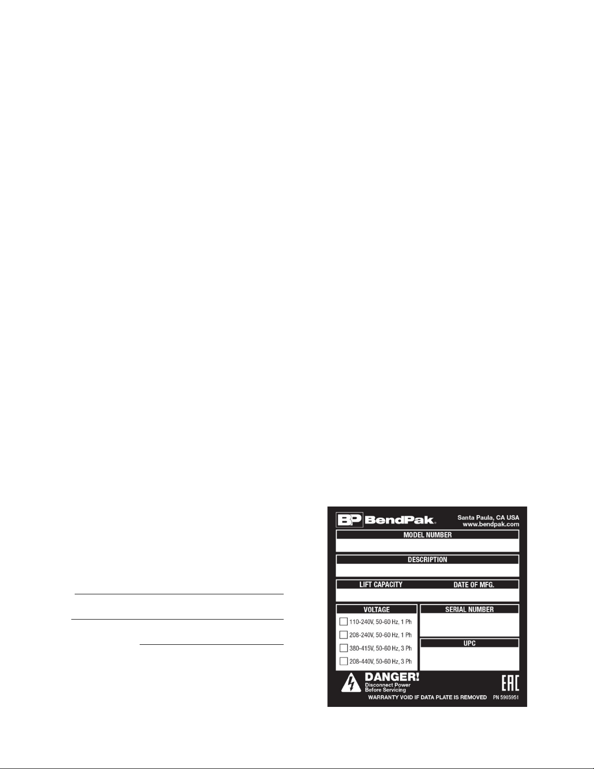
Unit Information. Enter the Model Number, Serial
Number, and the Date of Manufacture from the label
on your unit. This information is required for part or
warranty issues.
Model:
Serial:
Date of Manufacture:

Table of Contents
Introduction 3 Installation 12
Shipping Information 4 Operation 56
Safety Considerations 4 Maintenance 61
FAQ 6 Troubleshooting 63
Specifications 7 Wiring / Hydraulic Schematic 64
Components 9 Parts Diagrams 65
Installation Checklist 11 Labels 78
Introduction
This manual describes the GrandPrix (GP-7 Series) two-post Lifts from BendPak:
• GP-7. Two-post Lift, 7,000 lb. capacity, 74 inch rise, requires a 13-foot ceiling.
• GP-7LC. Two-post Lift, 7,000 lb. capacity, 64 inch rise, needs only a 10-foot ceiling.
• GP-7LCS. Two-post Lift, 7,000 lb. capacity, 54 inch rise, needs only a 9-foot ceiling.
All three models of the GrandPrix are ALI certified.
More information about the full line of BendPak products is available at bendpak.com.
This manual is mandatory reading for all users
installs, operates, maintains, or repairs them.
of GP-7 Series Lifts, including anyone who
⚠ DANGER Be very careful when installing, operating, maintaining, or repairing this equipment;
failure to do so could result in property damage, product damage, injury, or (in very
rare cases) death. Make sure only authorized personnel operate this equipment. All
repairs must be performed by an authorized technician. Do not make modifications
to the unit; this voids the warranty and increases the chances of injury or property
damage. Make sure to read and follow the instructions on the labels on the unit.
Keep this manual on or near the equipment so that anyone who uses or services it can read it.
If you are having issues, refer to the Troubleshooting section of this manual for assistance.
Technical support and service is available from your dealer, on the Web at bendpak.com/support,
by email at techsupport@bendpak.com, or by phone at (800) 253-2363, extension 196.
You may also contact BendPak for parts replacement information (please have the model and serial
number of your unit available) at (800) 253-2363, extension 191.
GrandPrix Two-Post Lifts 3 P/N 5900209 — Rev. D3 — Feb. 2020

Do not sign the bill of lading until
you have inspected the shipment.
parking
Shipping Information
Your equipment was carefully checked before shipping. Nevertheless, you should thoroughly inspect
the shipment
When you sign the bill of lading, it tells the carrier that the items on the invoice were received in good
condition.
items listed on the bill of lading are missing or damaged, do not accept the shipment until the carrier
makes a notation on the bill of lading that lists the missing or damaged goods.
If you discover missing or damaged goods
lading, notify the carrier at once and request the carrier to make an inspection. If the carrier will not
make an inspection, prepare a signed statement to the effect that you have notified the carrier (on a
specific date) and that the carrier has failed to comply with your request.
It is difficult to collect for loss or damage after you have given the carrier a signed bill of lading. If this
happens to you, file a claim with the carrier promptly. Support your claim with copies of the bill of
lading, freight bill, invoice, and photographs, if available. Our willingness to assist in helping you
process your claim does not make us responsible for collection of claims or replacement of lost or
damaged materials.
before
you sign to acknowledge that you received it.
after
after
you receive the shipment and have signed the bill of
If any of the
Safety Considerations
Read this manual carefully before using your new product.
product until you are familiar with all operating instructions and warnings. Do not allow anyone else to
operate the product until they are also familiar with all operating instructions and warnings.
Safety Information
Please note the following:
• GP-7 Series Lifts are two-post Lifts.
looking for a
• Only operate your Lift between temperatures of 41°F to 104°F (5°C to 40°C).
• The product should only be operated by authorized personnel. Keep children and untrained
personnel away from the product.
• Do not use the product while tired or under the influence of drugs, alcohol, or medication.
• Do not make any modifications to the product; this voids the warranty and increases the chances
of injury or property damage.
• Make sure all operators read and understand the Installation and Operation Manual. Keep the
manual near the device at all times.
• Make a visual inspection of the product before using it. Do not use the product if you find any
missing or damaged parts. Instead, contact an authorized repair facility, your distributor, or
BendPak at (805) 933-9970 or techsupport@bendpak.com.
• BendPak recommends making a
Replace any damaged or severely worn parts, decals, or warning labels.
Lift, visit the Bendpak website.
thorough
Do not install or operate the
Use them only for their intended purpose.
inspection of the product at least once a year.
If you are
GrandPrix Two-Post Lifts 4 P/N 5900209 — Rev. D3 — Feb. 2020

Symbols
Following are the symbols used in this manual:
⚠ DANGER Calls attention to a hazard that will result in death or injury.
⚠ WARNING Calls attention to a hazard or unsafe practice that could result in death or injury.
⚠ CAUTION Calls attention to a hazard or unsafe practice that could result in personal injury,
product damage, or property damage.
NOTICE Calls attention to a situation that could result in product or property damage.
Tip Calls attention to information that can help you use your unit better.
Liability Information
BendPak assumes no liability for damages resulting from:
• Use of the equipment for purposes other than those described in this manual.
• Modifications to the equipment without prior, written permission from BendPak Inc.
• Injury or death caused by modifying, disabling, overriding, or removing safety features.
• Damage to the equipment from external influences.
• Incorrect operation of the equipment.
GrandPrix Two-Post Lifts 5 P/N 5900209 — Rev. D3 — Feb. 2020

Frequently Asked Questions
Question: What kinds of Vehicles can I Lift on my GP-7 Series Lift?
Answer: Cars, light trucks, and SUVs; up to 7,000 lbs (3,175 kg) each.
Q: How long will it take to raise or lower my Vehicle?
A: About 45 seconds, depending on what locking position you use.
Q: Does the Lift have to be anchored in place?
A: Yes. Two-post Lift posts
only the Anchor Bolts that came with your Lift.
Q: How thick does my concrete have to be?
A: Concrete specifications are: 4.25 inches thick, 3,000 PSI, cured for a minimum of 28 days. Do not
install the Lift on cracked or defective Concrete. Anchor Bolts must be at least 6 inches from
cracks, expansion seams, or other inconsistencies in the Concrete. Do not install the Lift on
asphalt or any surface other than Concrete.
Q: Can I install my Lift outside?
A: No. GrandPrix Lifts are approved for indoor installation and use only. Outdoor installation is
prohibited.
must
be anchored. Your Lift comes with high-quality Anchor Bolts; use
Q: Which end is the front of the Lift?
A: To determine the front of your Lift, drive a Vehicle in straight and stop. The front of the Vehicle is
where the front of the Lift is.
Q: How long can I leave a Vehicle up?
A: Basically as long as you want, as long as the Lift is engaged on a Safety Lock. Once a Safety
Lock is engaged, gravity holds the Lift in position, so a loss of power has no effect; your Vehicle is
going to stay where you left it. Always leave your Lift either fully lowered or engaged on a Safety
Lock.
Q: How many Safety Lock positions does my Lift have?
A: Eleven, spaced every 4 inches / 101.5 mm.
Q: Does the Lift have a Front and Rear?
A: Yes and no. Because you can drive onto a two-post Lift from either opening, there is technically
no Front and Rear. However, most garages have an Approach side and a Wall side, so in that
case, the Wall side is the Front and the Approach side is the Rear.
Q: How do I know where to put the Adapters when I want to raise a Vehicle?
A: The Vehicle needs to be balanced, so you must put the Adapters (sometimes called Pads) so that
they contact the manufacturer’s recommended Lifting Points.
If you do not know where the
manufacturer’s recommended Lifting Points are on a Vehicle, you must find out
before you raise it
Engaging Lifts shows the Lifting Points for hundreds of Vehicles. Lifting It Right includes
information about how to raise Vehicles correctly.
. Your Lift came with books that will help: Vehicle Lifting Points for Frame
GrandPrix Two-Post Lifts 6 P/N 5900209 — Rev. D3 — Feb. 2020
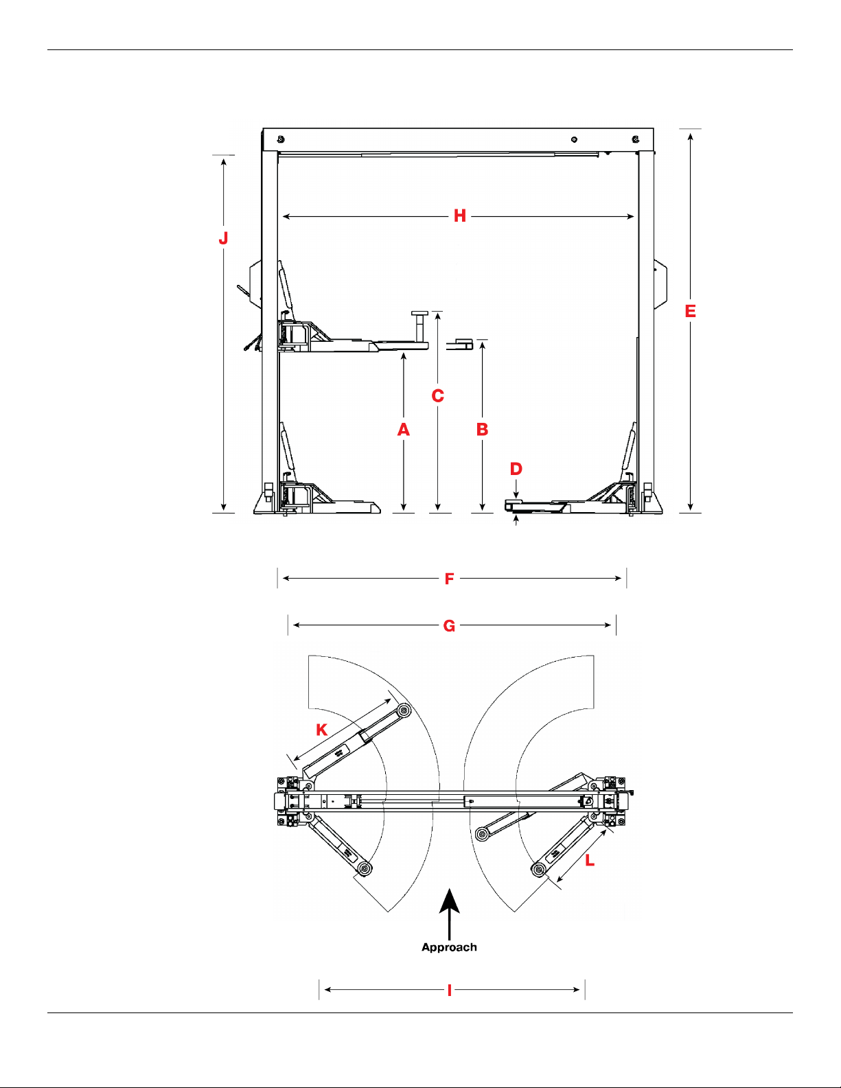
Specifications
GrandPrix Two-Post Lifts 7 P/N 5900209 — Rev. D3 — Feb. 2020

Model
GP-7LCS GP-7LC GP-7
Lifting capacity 7,000 lbs / 3,175 kg
A – Rise 54" / 1,372 mm 64" / 1,626 mm 74" / 1,880 mm
B – Rise + pad 58" / 1,473 mm 68" / 1,727 mm
C – Rise + pad + adapter 66" / 1,676 mm 76" / 1,930 mm
78" / 1,981 mm
86.5" / 2,197 mm
D - Minimum pad height 4.5" / 114 mm
E – Height overall 106.5" / 2,705 mm 118.5" / 3,010 mm 150" / 3,810 mm
F – Width overall 125" / 3,175 mm
G - Outside posts 119.5" / 3,035 mm
H – Inside posts 110" / 2,794 mm
I - Drive-thru width 89.5" / 2,273 mm
J - Floor to Trip Stop Tube 96" / 2,438 mm 108" / 2,743 140" / 3,556 mm
K - Reach (front arm min) 26" / 660 mm
K - Reach (front arm max) 42" / 1,067 mm
L - Reach (rear arm min) 28" / 711 mm
L - Reach (rear arm max) 47.5" / 1,207 mm
Standard Motor 220 VAC, 60 Hz, 1Ph
Time to full rise ~45 seconds
Maximum operating
2,940 PSI
hydraulic pressure
Sound ~70 dB
Specifications subject to change without notice.
GrandPrix Two-Post Lifts 8 P/N 5900209 — Rev. D3 — Feb. 2020

Components
GP-7 Series Lift components include:
• Powerside Post. The Powerside Post holds the Power Unit, the Safety Lock Release Handle,
the Lowering Handle, and the Power Disconnect Switch. The Powerside Post must go under the
Cylinder end of the Top Trough.
• Offside Post. The other Post. The Offside Post goes under the Cables end of the Top Trough.
• Power Unit. Provides hydraulic power to the Lift. Connects to a 220 VAC power source. Includes
the button that raises the Lift and an Hydraulic Fluid reservoir that must be filled before use.
• Safety Locks. Hold the Lift Arms while they are raised. Multiple Safety Locks let you select the
best Lift Arm height for your needs. Safety Locks use gravity and intelligent engineering to hold the
Lift Arms up once they are on a Safety Lock; even if the Lift loses power, the Lift Arms will stay
right where they are if they were left on a Safety Lock.
lowered or engaged on a Safety Lock.
• Slack Safety Locks. The Lift has a backup set of safety locks called the Slack Safeties. During
normal operation, the Lifting Cables hold back the Slack Safeties so that they do not engage. If,
however, a Lifting Cable were to break (which rarely happens!), the Slack Safety for the Lifting
Cable that broke would kick in immediately.
• Safety Lock Release Handle. Releases the Lift from its current Safety Lock. Used as part of
the lowering process.
• Lowering Handle. Lowers a Vehicle from a raised position when used with the Safety Lock
Release Handle.
• Lift Pads. Rubber pads that contact the Lifting Points of the Vehicles you raise. Also included
with your Lift are three sets of extensions (short, medium, tall) that can be used with the Lift Pads.
• Lift Arms. Extendable steel arms that attach to the Lift Heads. Lift Arms hold the Lift Pads; after a
Vehicle is moved into place, the Lift Arms are moved so that the rubber pads contact the Lifting
points on the Vehicle. The Lift Arms are one of the components that actually holds a Vehicle up.
• Lift Heads. Sometimes called carriages. Lift Heads move up and down in the Posts. They
connect to the Lift Arms, so when the Lift Heads move up, the Lift Arms (and anything on them)
also move up, thus raising the Vehicle.
• Top Trough. The beam across the top of the Lift; it supports the Lift’s structure and holds the
Hydraulic Cylinder and the Lifting Cables.
• Trip Stop Tube. Located on the underside of the Top Trough, the Trip Stop Tube stops upward
movement of the Lift. If you are raising a Vehicle and it hits the Trip Stop Tube, the Lift immediately
stops moving up.
• Power Disconnect Switch. Immediately interrupts main electrical power to the Lift. Used for
electrical circuit faults, emergency situations, or when Lift is undergoing service or maintenance.
• Thermal Disconnect Switch. Overload device that makes sure the equipment shuts down if
there is an overload or an overheated motor. The Lift’s motor has no thermal overload protection.
Only leave your GP-7 Series Lift fully
GrandPrix Two-Post Lifts 9 P/N 5900209 — Rev. D3 — Feb. 2020
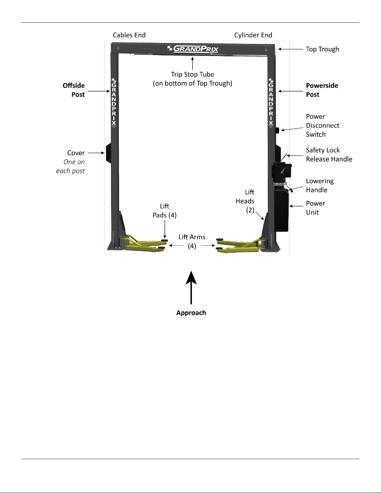
View is from rear of the Lift, looking towards the front. Model GP-7 shown. Not all components shown.
GrandPrix Two-Post Lifts 10 P/N 5900209 — Rev. D3 — Feb. 2020

Installation Checklist
Following are the steps needed to install a GP-7 Series Lift; perform them in this order.
☐ 1. Review the installation Safety Rules.
☐ 2. Plan for Electrical work.
☐ 3. Make sure you have the necessary Tools.
☐ 4. Select the installation Location.
☐ 5. Check the Clearances.
☐ 6. Review the installation Orientation.
☐ 7. Unload and Unpack the Components.
☐ 8. Install the Post Straps.
☐ 9. Put down Chalk Line Guides for the Posts.
☐ 10. About Embedment.
☐ 11. Install the Powerside and Offside Posts.
☐ 12. About the Lifting Cables.
☐ 13. Prepare the Top Trough.
☐ 14. Install the Top Trough.
☐ 15. Install the Power Unit (but do not connect it to power yet).
☐ 16. Install the Safety Assemblies and the Safety Cable.
☐ 17. Install the Trip Stop Tube.
☐ 18. Install the Microswitch and the Microswitch Cable.
☐ 19. About Fluid Contamination.
☐ 20. Install the Hydraulic Lines.
☐ 21. Connect the Lifting Cables.
☐ 22. Install the Safety Covers.
☐ 23. Install the Lift Arms.
☐ 24. Contact the Electrician.
☐ 25. Connect and prepare the Power Unit.
☐ 26. Adding Hydraulic Fluid.
☐ 27. Install the Power Disconnect Switch.
☐ 28. Install the Thermal Disconnect Switch.
☐ 29. Perform final Leveling of the Posts.
☐ 30. Torque the Anchor Bolts.
☐ 31. Lubricate the Lift.
☐ 32. Bleed the Hydraulic Cylinder.
☐ 33. Perform an Operational Test.
☐ 34. Review the Final Checklist.
GrandPrix Two-Post Lifts 11 P/N 5900209 — Rev. D3 — Feb. 2020

Installation
The installation process includes multiple steps. Perform them in the order listed.
Safety Rules
When installing the Lift, your safety depends on proper training and thoughtful operation.
⚠ WARNING Do not install this equipment unless you have automotive Lift installation training.
Only fully trained personnel should be involved in installing this equipment. Pay attention at all times.
Use appropriate tools and Lifting equipment, when needed. Stay clear of moving parts.
⚠ WARNING You must wear appropriate protective equipment: leather gloves, non-skid steel-
Plan Ahead for Electrical Work
Always use proper Lifting tools, such as a forklift or crane, to raise heavy
components. Do not install this equipment without reading and understanding this
manual and the safety labels on the unit.
toed work boots, eye protection, back belts, and hearing protection.
You will need to have a licensed, certified Electrician available at some point during the installation. All
of the tasks listed below must be performed by an Electrician.
⚠ DANGER All wiring
not a certified Electrician attempts these tasks, they could damage the Lift or be
electrocuted, resulting in serious injury or even death.
The Electrician needs to:
• Wire the 220 VAC power source to the Power Unit. This is generally done near the end
of the installation process; do not connect the Power Unit at the same time as you install it.
• Wire the Microswitch to the Power Unit. This is generally done at the same time as the
Electrician wires the power source to the Power Unit, as the Microswitch wiring goes between the
incoming power source and the Electrical Box on the Power Unit.
• Install a Power Disconnect Switch. A Power Disconnect Switch ensures that the equipment
shuts down in the event of an electrical circuit fault or emergency situation. Refer to Install a
Power Disconnect Switch for more information.
• Install a Thermal Disconnect Switch. A Thermal Disconnect Switch ensures that the
equipment shuts down in the event of an overload or an overheated motor. Refer to Install a
Thermal Disconnect Switch for more information.
The Electrician is responsible for providing:
• an appropriate power cable and plug for connecting to the power source
must
be performed by a licensed, certified Electrician. If someone who is
(wiring to connect the Microswitch to the Power Unit is included)
• a Power Disconnect Switch
• a Thermal Disconnect Switch
Additional information is supplied in the sections describing these tasks.
GrandPrix Two-Post Lifts 12 P/N 5900209 — Rev. D3 — Feb. 2020

Tools
You may need some or all of the following tools:
• Rotary hammer drill (or similar)
• ¾ inch carbide bit (conforming to ANSI B212.15-1994)
• Four-foot level, chalk line
• Open-end wrench set, SAE and metric
• Socket and ratchet set, SAE and metric
• Hex key wrench set, torque wrench, crescent and pipe wrenches
• Crow bar, hammer, needle-nose pliers, flat screwdriver
• Tape measure, 25 feet or above
• Forklift , shop crane, heavy-duty rolling dolly
• Two 12-foot ladders, two saw horses
Selecting a Location
When selecting the location for your GP-7 Series Lift, consider:
• Architectural plans. Consult the architectural plans for your desired installation location. Make
sure there are no contradictions between what you want to do and what the plans show.
• Available space. Make sure there is enough space for the Lift; front, back, sides, and
Refer to Specifications for exact measurements.
• Overhead obstructions. Check for overhead obstructions such as building supports, heaters,
lights, electrical lines, low ceilings, and so on.
• Power. You need a 220 VAC power source available for the Lift’s Power Unit.
• Outdoor installations. GrandPrix Lifts are approved for indoor installation and use only.
Outdoor installation is prohibited
• Floor. Only install the Lift on a flat, Concrete floor; do not install on asphalt or any other surface.
The surface must be level; do not install if the surface has more than three degrees of slope.
.
above
.
⚠ WARNING Installing your Lift on a surface with more than three degrees of slope could lead to
injury or even death. Only install GrandPrix Lifts on a level floor (defined as no more
than 3/8 of an inch difference over the installation area). If your floor is not level,
consider making the floor level or using a different location.
• Concrete specifications. Do not install the Lift on cracked or defective concrete. Anchor Bolts
must be at least 6 in from cracks, expansion seams, or other inconsistencies in the Concrete.
Make sure the concrete is at least 4.25 inches thick, 3,000 PSI, and cured for at least 28 days.
⚠ CAUTION BendPak Lifts are supplied with installation instructions and concrete anchors that
meet the criteria set by the American National Standard “Automotive Lifts – Safety
Requirements for Construction, Testing, and Validation”, ANSI/ALI ALCTV-2011.
You are responsible for any special regional structural and/or seismic anchoring
requirements specified by any other agencies and/or codes such as the Uniform
Building Code (UBC) and/or International Building Code (IBC).
GrandPrix Two-Post Lifts 13 P/N 5900209 — Rev. D3 — Feb. 2020
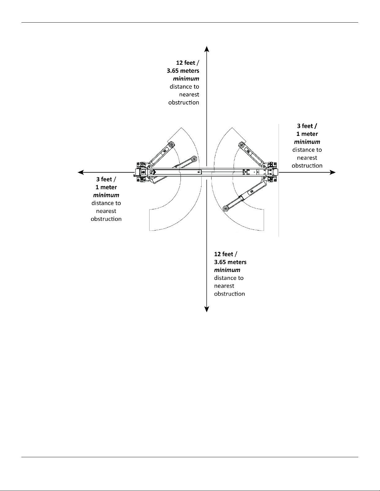
Clearances
GrandPrix Two-Post Lifts 14 P/N 5900209 — Rev. D3 — Feb. 2020
Installation Orientation
To determine the front of your Lift, drive a Vehicle in straight (do not back it in) and stop. The front of
the Lift is where the front of the Vehicle is.
The approach is the direction you drive a Vehicle onto the Lift. Generally the approach is from the rear
of the Lift towards the front of the Lift.
The orientation of the procedures and drawings in this manual is looking at the Lift from the rear,
towards the front, unless specified otherwise. This is the same orientation as shown in the image in the
Components section and in the drawing below.
This means that:
• The Powerside Post (which holds the Lowering Handle and the Power Unit) is on the right, the
Offside Post is on the left.
• The
• The two angled arms are at the ‘front’ of the Lift.
• The two straight arms are at the ‘rear’ of the Lift.
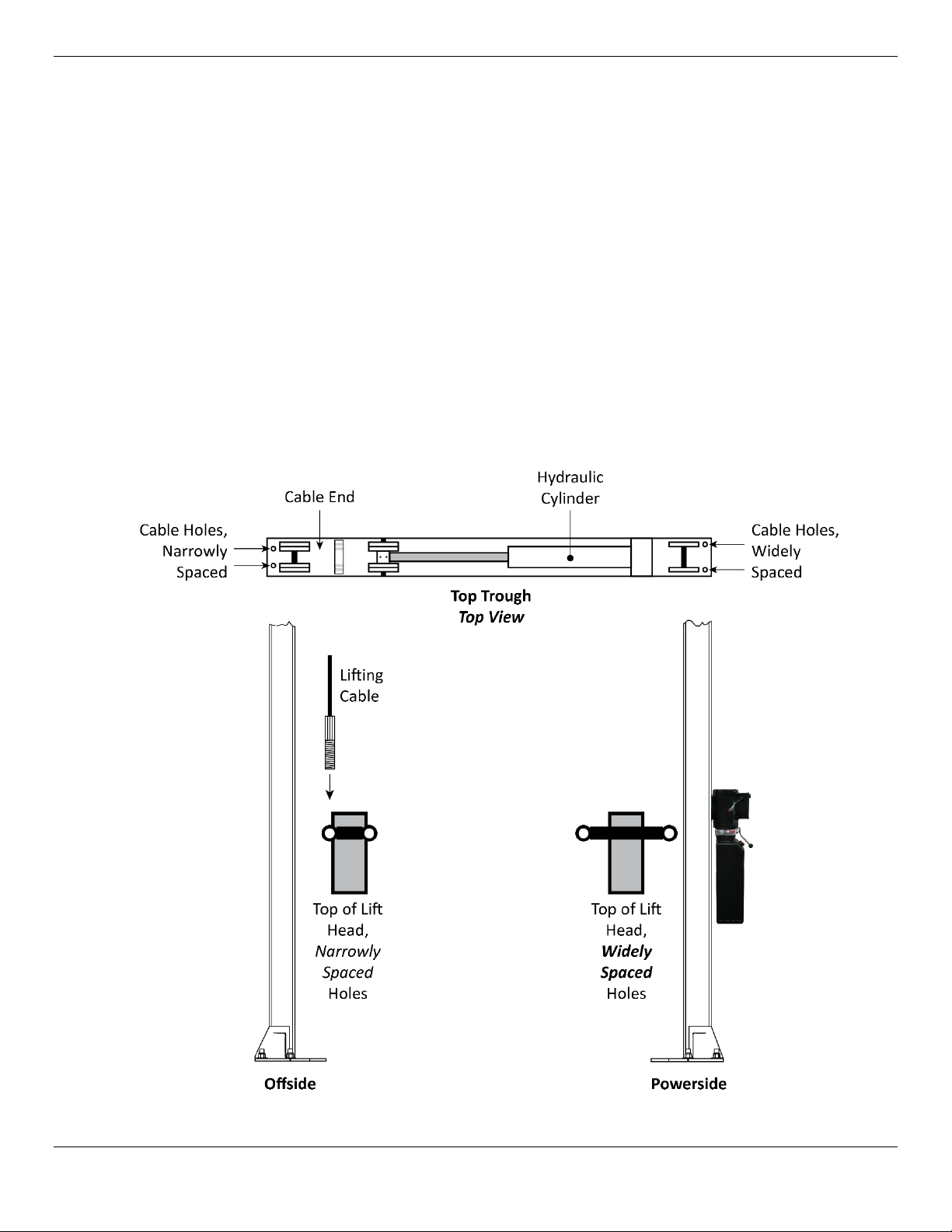
The following drawing shows how to orient the Powerside and the Offside Posts.
Hydraulic Cylinder end
of the Top Trough is on the right, above the Power Unit.
Not necessarily to scale. Not all components shown.
GrandPrix Two-Post Lifts 15 P/N 5900209 — Rev. D3 — Feb. 2020

To identify the Powerside Post and the Offside Post, look at the tops of the Lift Heads in each of the
Posts:
• Powerside Post. The Lift Head with widely spaced holes is the Powerside Post. The Powerside
Post must go under the Cylinder End of the Top Trough.
• Offside Post. The Lift Head with the narrowly spaced holes must be the Offside Post. The
Offside Post must go under the Cable End of the Top Trough.
must
Important: You
the Lift will not work correctly.
orient the Powerside and Offside Posts this way. If they are set up wrong,
Unloading and Unpacking
Unload the Lift components as close to the installation location as possible.
Once the components are unloaded, they are your responsibility to move around. The Lift includes a
number of heavy pieces, so the closer you unload them to the installation location, the better off you
will be.
⚠ WARNING Some Lift components are very heavy; if handled incorrectly, they can damage
materials like tile, sandstone, and brick. Try to handle the Lift components just
twice: once when delivered and once when moved into position. You must have a
forklift or crane to move some of the Lift components into position. Use care when
moving them around.
GrandPrix Two-Post Lifts 16 P/N 5900209 — Rev. D3 — Feb. 2020
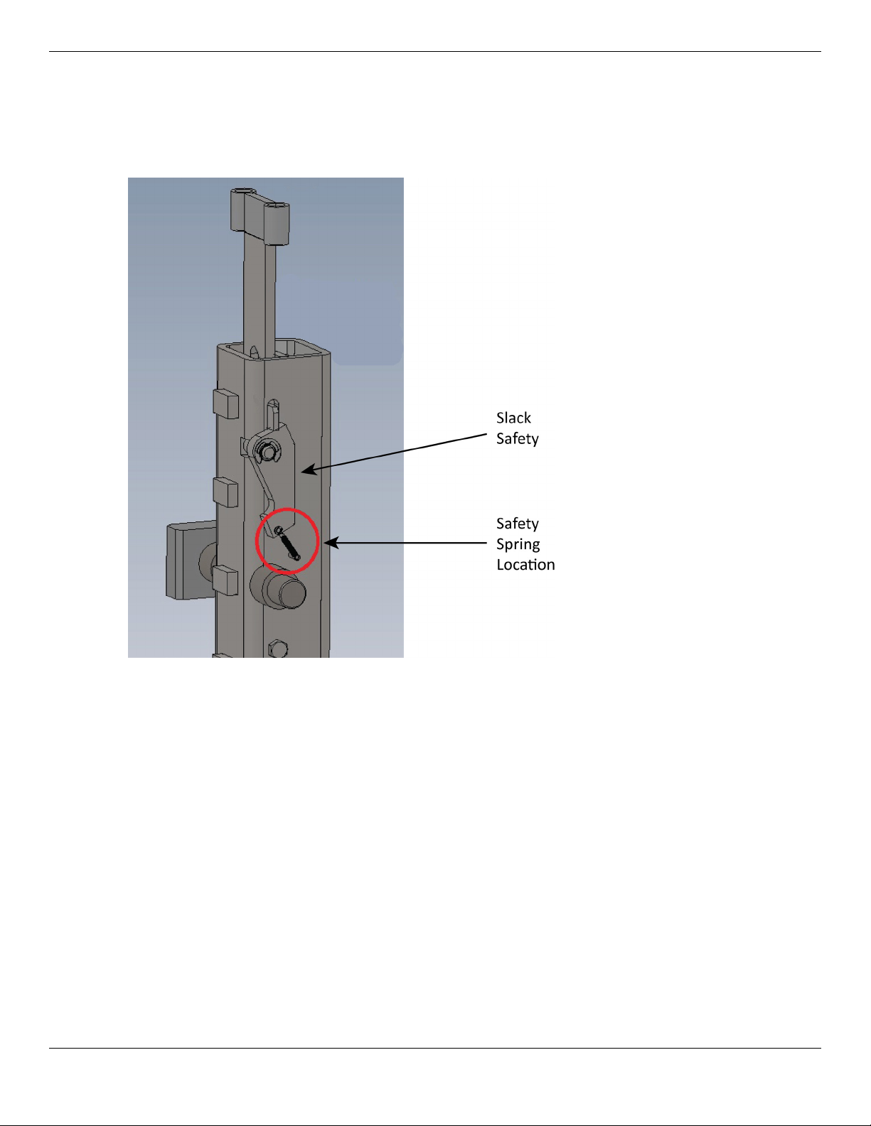
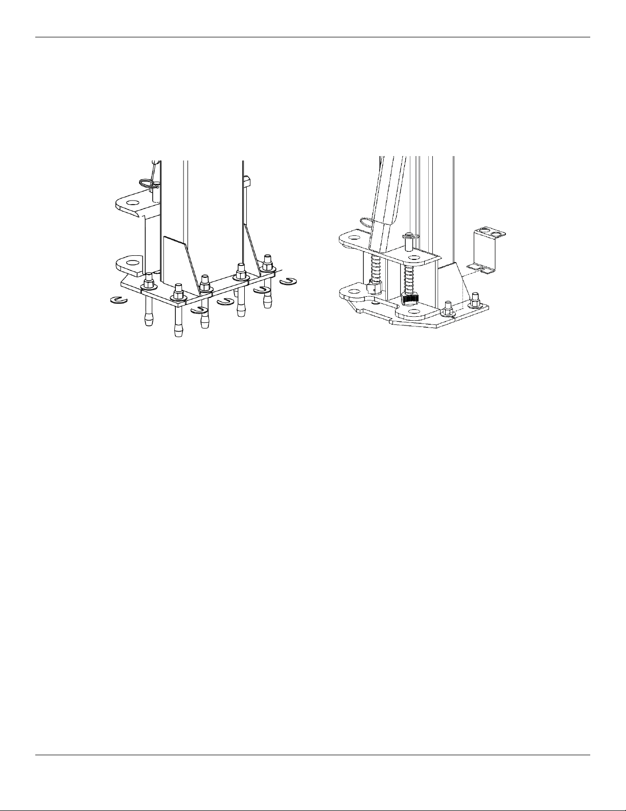
Checking the Safety Spring
Before standing up the Posts of the Lift, check to make sure the Safety Spring has not been knocked
out of place during transport.
The Safety Spring should be in position, as shown below.
Post removed for clarity. Not all components shown.
To determine whether or not the Safety Spring is in place, either slide the Lift Head up so that it comes
out of the Post enough so that you can see the Safety Spring and verify it is in place or take a flashlight
and shine it down through the Post to visually verify that the Safety Spring is in place.
If the Safety Spring has come loose during transport:
1. Slide the Lift Heads up until the Safety Spring is accessible.
2. Reconnect the Safety Spring in the location shown above.
3. Slide the Lift Heads back down.
Because the Lifting Cables are not in place, the Slack Safeties will engage when you move the Lift
Head back down (they are prevented from engaging during normal operation).
Manually hold the Slack Safeties so that they cannot engage as you lower the Lift Head.
Important: You
must
disengage the Slack Safeties before proceeding with the installation.
GrandPrix Two-Post Lifts 17 P/N 5900209 — Rev. D3 — Feb. 2020
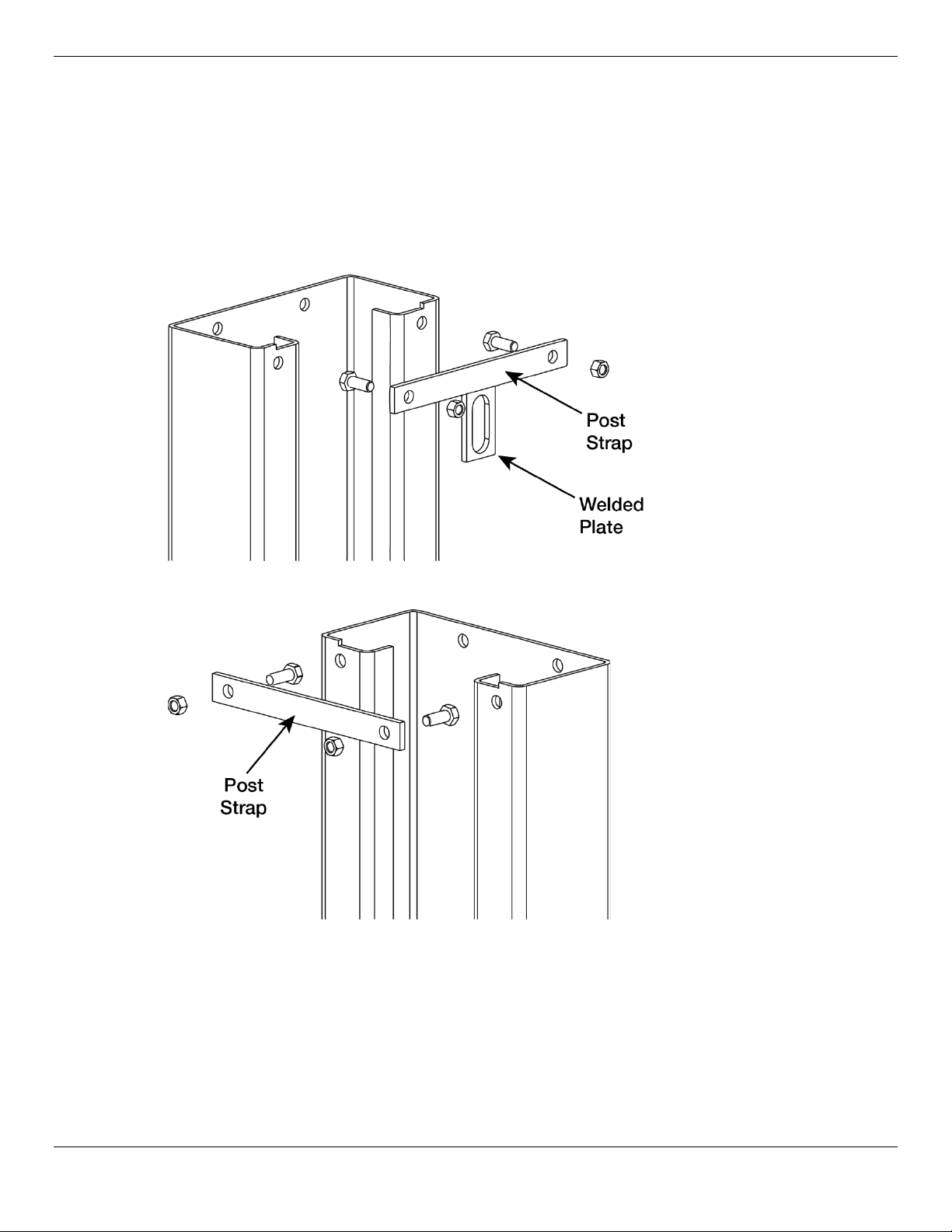
Installing the Post Straps
You may want to install the Post Straps on their Posts
but if you install them after standing up the Posts, you will need a ladder to reach them.
Important: The Post Strap with the
without the welded plate goes on the Offside Post.
To install the Post Straps:
1. Bolt the Post Strap
with the welded plate
welded plate
prior
to standing them up. It is not required,
goes on the Powerside Post. The Post Strap
to the Powerside Post.
2. Bolt the other Post Strap (no welded plate) to the Offside Post.
GrandPrix Two-Post Lifts 18 P/N 5900209 — Rev. D3 — Feb. 2020
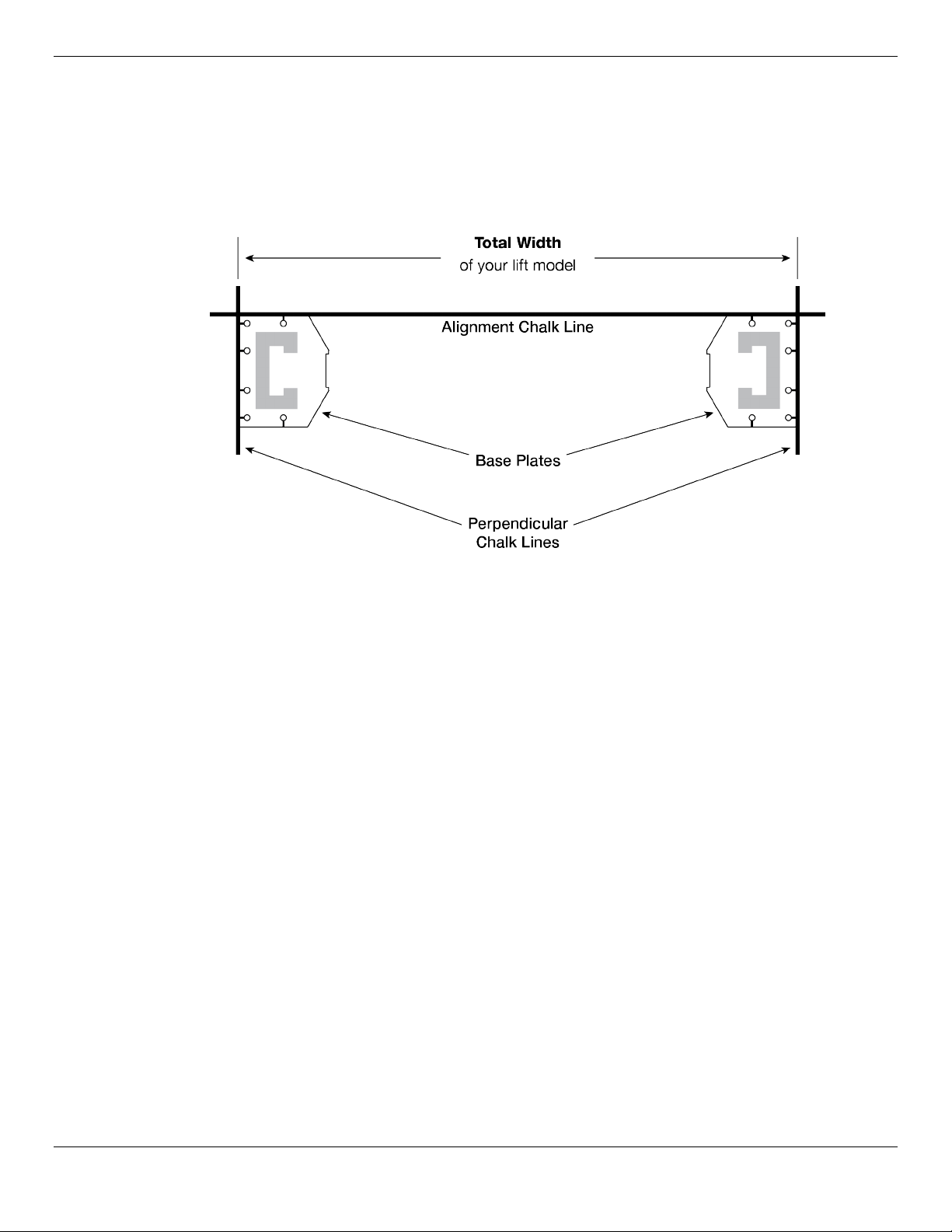
Putting in Chalk Line Guides
Based on the specifications for your Lift, create Chalk Line Guides on the ground for the two posts
prior to moving them into position.
Use the Width Overall value in Specifications
the Chalk Line Guides. The Width Overall value is defined as the distance from the back of one base
plate to the back of the other base plate.
To add Chalk Line Guides:
1. Decide where you want to locate the Lift.
for your Lift model
to determine where to place
2. Create an alignment chalk line at the desired location.
The alignment chalk line must be longer than the Width Overall setting for your Lift model.
3. Create two perpendicular chalk lines at 90° angles to the alignment chalk lines.
The two perpendicular chalk lines must be x distance from each other, where x is the Width
Overall setting for your Lift model.
4. When you move the posts into position, put the corners of the base plates into the corners created
by the Chalk Line Guides.
GrandPrix Two-Post Lifts 19 P/N 5900209 — Rev. D3 — Feb. 2020
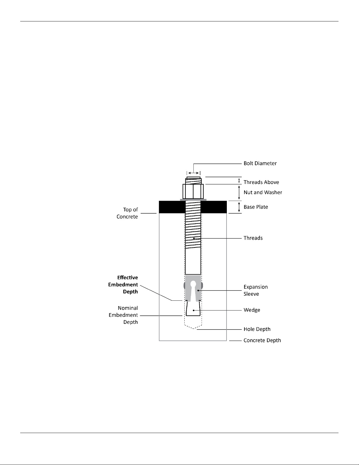
About Embedment
Anchor Bolts (also called Wedge Anchors) get their holding strength from how far down into the Hole
the Anchor Bolt is installed (called embedment) and how forcefully the Expansion Sleeve presses into
the Concrete (based on how much torque is applied).
To get enough embedment, you have to understand Effective Embedment, which means the location
in the Hole where the Expansion Sleeve presses into the Concrete. This is where the Anchor Bolts
create holding strength; the further down into the Hole, the greater the holding strength.
(The technical definition of Effective Embedment is the distance from the surface of the base material
to the deepest point at which the load is transferred to the base material; the “base material” in our
case being the Concrete into which the Anchor Bolts are being installed.)
Some people confuse Effective Embedment with Nominal Embedment, which is how far down into the
Hole the bottom of the Anchor Bolt is.
As shown below, the two are not the same. Nominal Embedment is
to the base material, Effective Embedment is.
not
where the load is transferred
Not necessarily to scale.
The Anchor Bolts shipped with your product have letters stamped into their tops, showing their length.
For example:
• 4.75 in / 120 mm Anchor Bolts are stamped with a G.
• 6.3 in / 160 mm Anchor Bolts are stamped with a J.
GrandPrix Two-Post Lifts 20 P/N 5900209 — Rev. D3 — Feb. 2020

Installing the Posts
We strongly recommend having multiple people working together to install the Posts.
Concrete specifications are:
• Depth: 4.25 inches / 108 mm thick, minimum
• PSI: 3,000 PSI, minimum
• Cured: 28 days, minimum
Anchor Bolt specifications are:
• Length: 6.3 inches / 160 mm
• Diameter: .75 inch / 19 mm
• Anchor torque: 85 – 95 pound feet (never less than 80 or more than 110)
• Effective embedment: 3.25 inches / 82.5 mm or more
⚠ WARNING Your Concrete and Anchor Bolts must meet these specifications. Only install your
Lift on a Concrete surface. If you install a Lift on asphalt or any other surface, or
your Concrete or Anchor bolts do not meet these specifications, it could lead to
product damage, Vehicle damage, personal injury, or even loss of life.
BendPak Lifts are supplied with installation instructions and concrete fasteners meeting the criteria as
prescribed by the American National Standard “Automotive Lifts – Safety Requirements for
Construction, Testing, and Validation” ANSI/ALI ALCTV-2006.
⚠ WARNING Use only the ALI-certified Anchor Bolts that came with your GP-7 Series Lift. If you
use components from a different source, you void your warranty and compromise
the safety of everyone who installs or uses the Lift.
Lift buyers are responsible for conforming to all regional, structural, and seismic anchoring
requirements specified by any other agencies and/or codes, such as the Uniform Building Code and/or
International Building Code.
not
Tip Consider
the Top Trough and doing final leveling may be easier if there is a little play in the Posts.
To install the posts:
1. Using a forklift, crane, or heavy-duty rolling dolly, move the Posts to the Chalk Line Guides you
created earlier.
2. Stand up each Post, one at a time, and move the appropriate corners into the corners created by
the Chalk Line Guides.
3. Double check your measurements against the Specifications for your GP-7 Series Lift model:
Distance from back of one base plate to back of other base plate: Width Overall value
Distance from inside of one Post to inside of other Post: Inside Posts value
4. Using the Base Plates as guides, drill each hole 4 inches deep.
torqueing the Anchor Bolts into position quite yet. Two reasons: installing
Do not drill all the way through the Concrete; if you punch completely through the slab, you could
compromise the holding strength of the Anchor Bolts.
GrandPrix Two-Post Lifts 21 P/N 5900209 — Rev. D3 — Feb. 2020
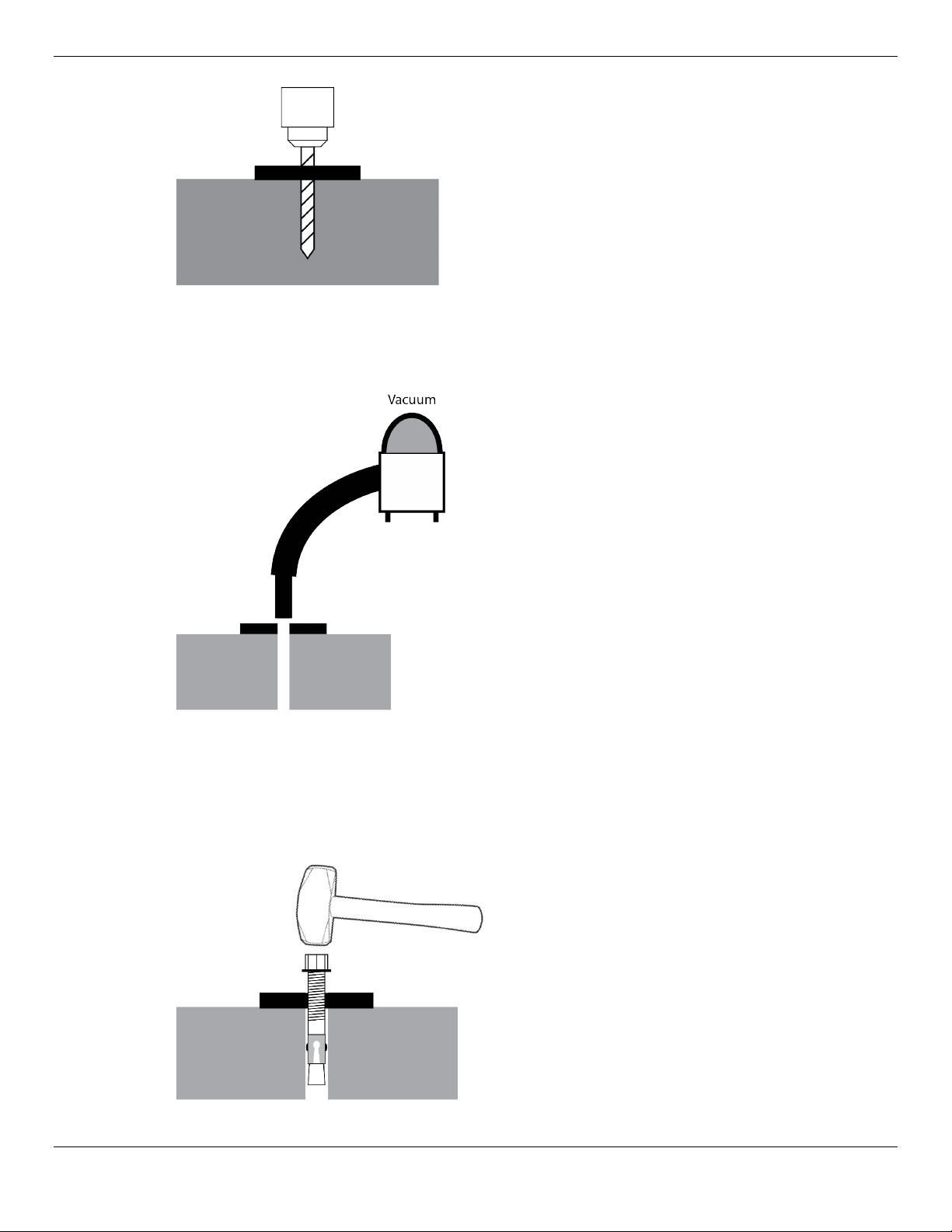
Go in straight; do not let the drill wobble.
Use a carbide bit (conforming to ANSI
B212.15-1994).
The diameter of the drill bit must be the same as the diameter of the Anchor Bolt. So if you are
using a ¾ inch diameter Anchor Bolt, for example, use a ¾ inch diameter drill bit.
5. Vacuum each hole clean.
BendPak recommends using a vacuum
to get the hole very clean.
You can also use a wire brush, hand
pump, or compressed air; just
make
sure to thoroughly clean each
.
hole
Do
not
ream the hole. Do
hole any wider than the drill bit made it.
Important: The holding strength of an Anchor Bolt is partially based on the how cleanly the
Expansion Sleeve presses against the Concrete. If the hole is dirty or too wide, there
is less holding strength.
6. Make sure the Washer and Nut are in place, then insert the Anchor Bolt into the hole.
The Expansion Sleeve of the Anchor Bolt
may prevent the Anchor Bolt from passing
through the hole in the Base Plate; this is
normal. Use a hammer or mallet to get the
Expansion Sleeve through the Base Plate
and into the hole.
Even using a hammer or mallet, the
Anchor Bolt should only go into the hole
part of the way; this is normal. If the
Anchor Bolt goes all the way in with little or
no resistance, the hole is too wide.
not
make the
GrandPrix Two-Post Lifts 22 P/N 5900209 — Rev. D3 — Feb. 2020
Once past the hole in the Base Plate, the Anchor Bolt eventually stops going down into the hole as
the Expansion Sleeve contacts the sides of the hole; this is normal.
7. Hammer or mallet the Anchor Bolt the rest of the way down into the hole.
Stop when the Washer is snug against the Base Plate.
8. Plumb each Post; install any needed Shims or the optional Adapter Trays (which let you stack the
provided Auxiliary Adapters — also called Extenders — conveniently near the Lift Arms).
9.
Do not torque the Anchor Bolts at this point
.
Installing the Top Trough and doing final leveling (both of which are done later in the installation
process) are both easier if there is a little bit of play in the Posts.
If you torque the Anchor Bolts now, there will not be any play in the Posts, making it more difficult
to install the Top Trough and do final leveling.
GrandPrix Two-Post Lifts 23 P/N 5900209 — Rev. D3 — Feb. 2020
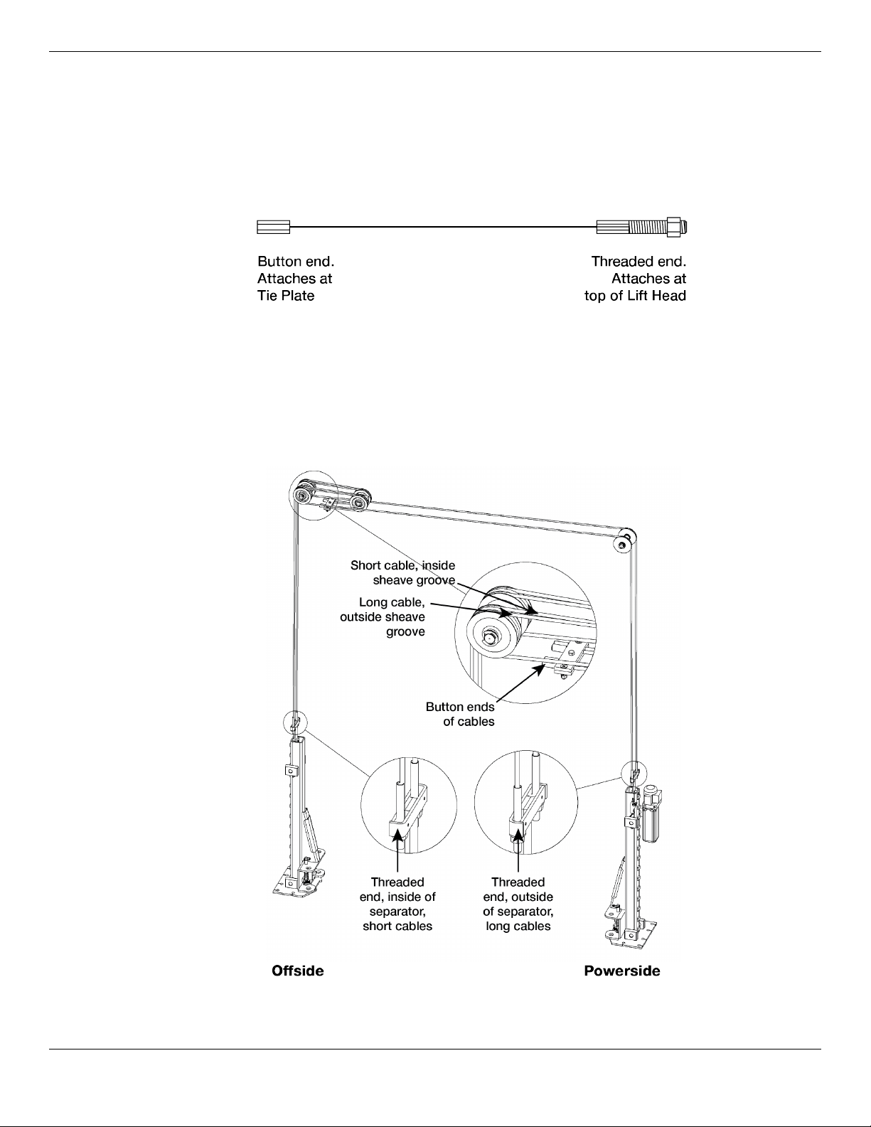
About the Lifting Cables
⚠ CAUTION We strongly recommend wearing gloves while handling the Lifting Cables.
GP-7 Series Lifts use four Lifting Cables: two Long Cables and two Short Cables. The following
drawing shows the
exaggerated in this drawing to make it easier to see the two types of ends.
The Button end of all four cables
the upper left corner in the drawing below).
The Threaded end of the two Short Cables end at the Offside Lift Head. The Threaded end of the two
Long Cables end at the Powerside Lift Head.
The following drawing shows the routing for the Lifting Cables. The Top Trough and both posts have
been removed so you can see just the Lifting Cables and associated components.
two different types of ends
start
at the same place (at the Tie Plate, in the Top Trough, shown in
on these cables. Note that the ends are
Both short cables are exactly the same; it does not matter what order you install them in. Both long
cables are also exactly the same.
GrandPrix Two-Post Lifts 24 P/N 5900209 — Rev. D3 — Feb. 2020
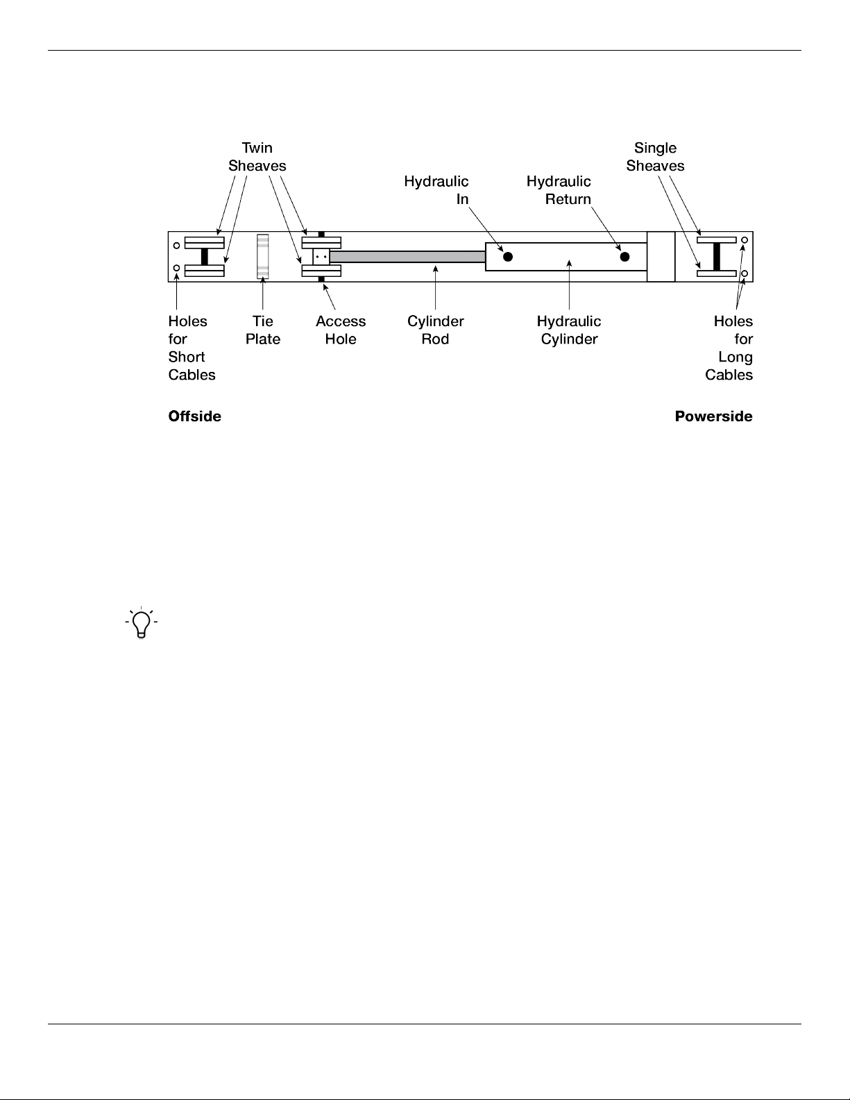
The following drawing is a top view of the components of the Top Trough. Not every component is
shown, just the components relevant to installing the Lift. The Offside Post is on the left, the Powerside
Post is on the right.
Preparing the Top Trough
The Top Trough goes between the two posts at the top of the Lift.
To prepare the Top Trough, you need to:
• Route the Lifting cables.
• Route the safety cables.
• Connect the hydraulic cables (but not the hydraulic lines).
Tip We strongly recommend raising the Top Trough off the ground when performing these
preparation tasks; a saw horse works great for this, for example.
Routing the Lifting Cables
The Lifting cables move the Lift Heads and Lift Arms up and down.
To route the Lifting cables:
1. Make sure you have two Long Cables and two Short Cables.
All cables have ID tags showing their lengths.
2. Extend the Cylinder Rod until the Pullblock sheave pin lines up with the Access Hole in the Top
Trough.
This can be done by carefully pulling the Cylinder Rod by hand or carefully using an air gun
(remove both plugs, insert air gun in port furthest from the Cylinder Rod, push air in).
⚠ CAUTION Be careful not to damage the Cylinder Rod when extending it. Do not exceed 50
PSI if using an air gun. If Cylinder Rod is not extending, stop and use a cable puller
or other pulling device. Keep hands clear of pinch points.
GrandPrix Two-Post Lifts 25 P/N 5900209 — Rev. D3 — Feb. 2020
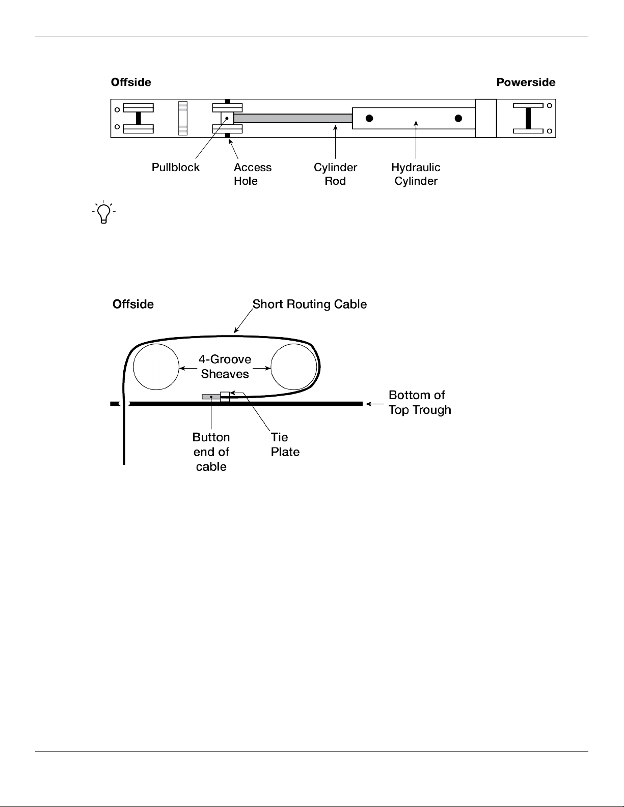
This drawing is looking down on the Top Trough from above.
Tip BendPak recommends installing the two Short Cables (which go on the inner sheaves)
first, then proceed to the two longer cables (which go on the outer sheaves). You can do
it any way you want, but these instructions go in that order.
3. Put the Button End of first Short Cable into position at the Tie Plate.
The following drawing is a side view of how a Short Cable gets routed over the sheaves.
4. Route the Short Cable under the bottom of the Cylinder side sheave and then over the top of it,
over the top of the Offside end sheave, and down through the hole in the bottom of the Top
Trough.
5. Do the same thing for the second short cable.
Make sure to put the Button End of the second Short Cable on the other side of the Tie Plate from
the Button End of the first Short Cable.
6. Put the Button End of the first Long Cable into position at the Tie Plate, on the outside of either of
the two Short Cables (it does not matter which one you do first).
GrandPrix Two-Post Lifts 26 P/N 5900209 — Rev. D3 — Feb. 2020
 Loading...