

Grandio ELITE 8x12, ELITE 8x16, ELITE 8x24, ELITE 8x20 User Manual
GRANDIO
GREENHOU S E S
GRANDIO ELITE 8x12, 8x16, 8x20, 8x24 KIT MANUAL
INCLUDES INSTRUCTIONS FOR BACK DOOR TRANSFORMATION
®
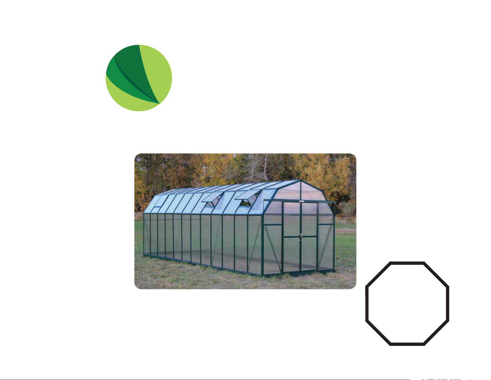
Grandio Elite 8x24 Shown In Image
GREENHOUSE USER MANUAL
© 2013 Grandio Greenhouses, Backyard Living Source Inc. All rights reserved
April 15, 2016 Manual Edition Extendable Greenhouses
STOP
This manual is for
8x12, 8x16, 8x20 & 8x24.
If building an 8x8 with
no extensions refer to
that manual.
GRANDIO
GREENHOU S E S
®
IMPORTANT! PLEASE READ BEFORE BEGINNING ASSEMBLY
Before you begin, take time to complete this check list.
Dear Valued Customer,
We would like to congratulate you on your new
Grandio Greenhouse purchase. We are confident
that you have made the right decision in choosing Grandio. Our greenhouses are made with
high quality aluminium and polycarbonate and
will last for many garden seasons to come.
Please take the time to carefully read this
instruction manual for an easier and more
enjoyable assembly experience.
Cheers!
Grandio Greenhouses
Save this owner’s manual for future
reference and if you need our help.
CONTACT OUR CUSTOMER SERVICE
DEPARTMENT at:
1-866-448-8231
Take inventory of all parts using the parts list at the back of this manual on
pages 68-78. The base kit parts list is at the front on page 12 and 13. The back
door transformation kit parts list is on page 78.
Be cautious where you place the polycarbonate panels as they will burn grass
or plants if left on top of them in direct sunlight. Note that clear film side of
panels should always face the sun and white film side faces inside green-
house. Panels may scratch easily so be careful what you clean them with.
Plan out when and where you are going to place the greenhouse, we recommend that you place it in an area that will receive direct sunlight and will be
protected from the wind as much as possible
It will take at least (2) people to put the greenhouse together.
Before your build, make sure you are allowed to build it! Consult all building
codes, as well as City or Municipality ordinances and HOA’s, as you may need
a permit or documentation before you build.
Contact your insurance company to make sure your Grandio Greenhouse will
be covered on your policy.
Hours: 8:30a.m.-5:00p.m. Monday through
Friday (Mountain Standard Time)
Backyard Living Source
9543 W. Emerald St., Suite 101
Boise, ID 83704
www.grandiogreenhouses.com
Call your local utilities companies before digging.
Do not attempt to begin construction on a windy day, plan to complete
assembly in one day. Damage caused by incomplete assembly is not covered
by warranty.
Your greenhouse should be built on a flat level surface allowing for drainage.
Read this entire manual to get familiar with all pieces and parts prior to
beginning assembly. Follow the steps outlined in the order presented!
1
IMPORTANT! SAFETY INSTRUCTIONS
FAILURE TO FOLLOW THESE WARNINGS MAY RESULT IN SERIOUS INJURY OR
PROPERTY DAMAGE AND WILL VOID WARRANTY.
To ensure safety, do not attempt to assemble this product without following the instructions carefully. Check entire box and
inside all packing material for parts and/or additional instruction materials. Before beginning assembly, read the instruc-
tions and identify all parts using the hardware identifier and parts list on pages 68-78. Complete assembly and
proper usage are essential to reduce the risk of accident or injury when using your Grandio Greenhouse.
CAUTION: Do not leave polycarbonate panels laying on grass or leave in the sun or extreme heat, keep in a cool
dry place until they are to be installed!! (May cause burning to plants or grass if left directly on top of them, also may
damage panels due to the protective lm adhering to panels.) Panels may scratch easily. Do Not use solvent cleaners.
• Each of the polycarbonate panels have a clear lm side that should always face the sun, and a white lm side which faces inside.
The clear side has a UV coating and we recommend marking a small “x” on a corner of each panel to determine which side has the
UV Coating as you cannot visually determine with your eye in the case of future disassembly.
• Due to shipping, the grooves of some of the aluminum proles may be too small to insert into the polycarbonate sheet, you may
carefully use a screwdriver to pry the framework open so the polycarbonate sheet can be inserted smoothly.
• Do not use or store hot objects such as grills, blow torches, welding equipment, etc. in or near your greenhouse.
• Do not allow children or pets to play in greenhouse or in the set up area until assembly is complete.
• If using a ladder during assembly, use extreme caution.
• A clean level surface is essential to maintaining the solid integrity of the structure, Install the base correctly as described in
manual. Please anchor the greenhouse down to a rm and level base. If not properly installed warranty may be void.
NEEDED FOR ASSEMBLY
• Tape Measure • 2 Step Ladders • Safety Glasses
• Level • Work Gloves • Drill
• Carpenter Square • Permanent Marker • Folding Utility Table
• At Least 2 Adults • Masking Tape • Silicone Caulk
2
GRANDIO
TIP
the helpful tips we have provided that will
make installation more ecient.
When you see this icon
pay special attention to

GRANDIO
GREENHOU S E S
®
ASSEMBLY INSTRUCTION STEPS
PREPARE FOR ASSEMBLY
STEP ONE: BASE ASSEMBLY
STEP TWO: FRONT ASSEMBLY
STEP THREE: BACK ASSEMBLY
STEP FOUR: MIDDLE ASSEMBLY
STEP FIVE: EXTENSION ASSEMBLY
STEP SIX: DOOR ASSEMBLY
STEP SEVEN: INTERIOR ROOF SUPPORTS
Introduction.............................................................................1
Safety Instructions.................................................................2
Prepare For Assembly...........................................................4
Box Congurations ...............................................................5
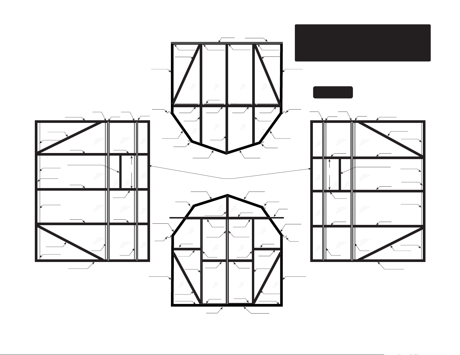
Diagrams of Assembled Grandio Elite Sizes
8x8, 8x12, 8x16, 8x20, 8x24.........................6-10
Base Kit Assembly Information.......................................11
Base Kit Parts Lists........................................................12-13
8x12 Base Kit........................................................................14
8x16 Base Kit........................................................................15
8x20 Base Kit........................................................................16
8x24 Base Kit........................................................................17
Base Kit Assembly and Installation........................18-20
Front Wall Assembly....................................................21-26
Back Wall Assembly.....................................................27-32
Middle Assembly.........................................................33-38
Extension Assembly...................................................39-45
8x20 and 8x24 Extension Assembly.....................46-50
Extension Assembly Continued.............................51-60
Door Assembly.............................................................61-66
Interior Roof Supports.....................................................67
GRA-ELI-8A Parts List.................................................68-70
GRA-ELI-8P Parts List........................................................71
GRA-ELI-4X Parts List.................................................72-74
GRA-ELI-8XA Parts List..............................................75-76
GRA-ELI-8XP Parts List....................................................77
GRA-ELI-BD Parts List......................................................78
Warranty..............................................................................79
3
PREPARE FOR GREENHOUSE ASSEMBLY
IMPORTANT: BASE KIT ASSEMBLY &
GREENHOUSE PLACEMENT
Before assembling your new greenhouse, a proper
foundation must be prepared. A number of anchoring options are acceptable, based on wind and
ground conditions in your area.
Pre-read pages 11-20 for base kit assembly information.
Go to www.grandiogreenhouses.com for foundation ideas and tour our online learning center for
tips, tricks and videos for putting your greenhouse
together.
IMPORTANT: POLYCARBONATE PANELS
The UV-Protected side is covered with clear lm and
must face toward the sun. The side covered in white lm
will always face the interior of the greenhouse. We
suggest you peel all lm o completely prior to assembly and use a permanent marker to place a small “X” on
the lower right corner of each panel on the clear side
that faces the sun, each panel has a sticker labeling the
panel number and this side always faces the sun or
outward as well. DO NOT REMOVE LABELS UNTIL
YOU INSTALL PANELS. The “X” is suggested in case
you dis-assemble your greenhouse in the future so you
may identify which side has the UV coating. Always use
gloves when handling the polycarbonate panels as the
edges can be very sharp.
Sun
Transparent Clear Film
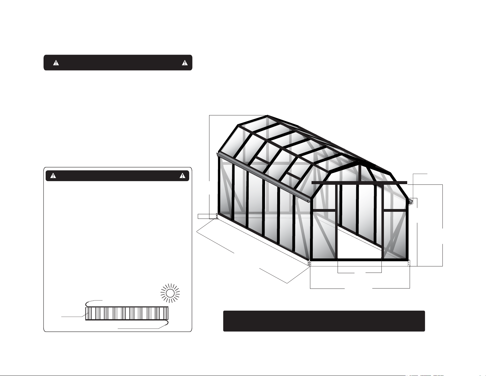
ROOF PEAK HEIGHT
95 5/16”
2421 mm
BASE
3
1/4
”
82.6 mm
143
LEFT SIDE
3652 mm
8X12
8X12 GRANDIO ELITE BARN STYLE
GREENHOUSE DIMENSIONS
3/4
”
44”
1117.6 mm
97 7/16”
2475 mm
1
3/4
” 44.4mm
GUTTERS
61”
1549.4 mm
EAVE HEIGHT
DOOR HEIGHT
74”
1879.6 mm
Polycarbonate
Panels
Opal White Film
*SEE BASE KIT ASSEMBLY SECTION FOR ALL
GREENHOUSE BASE DIMENSIONS ON PAGES 14-17.
4
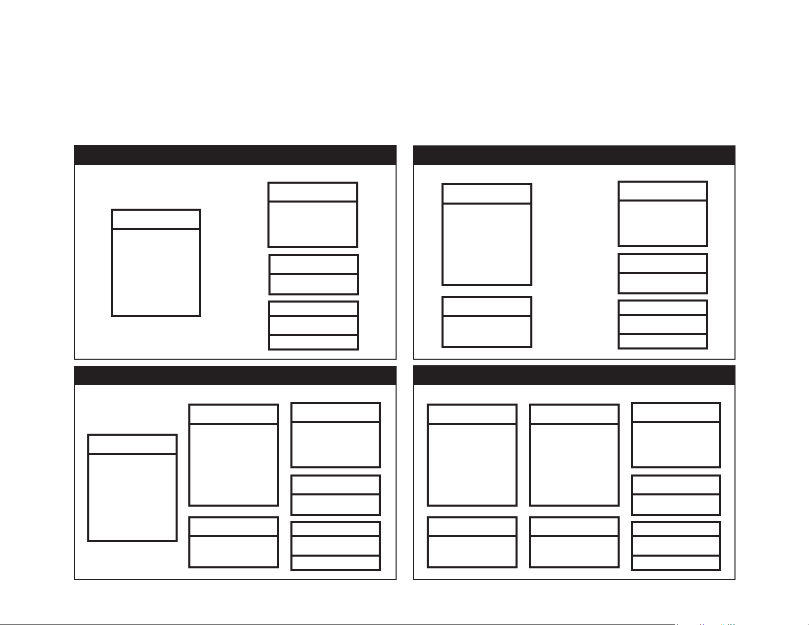
EXTENSION KIT BOX CONFIGURATIONS
We recommend that you lay all of your boxes out as shown below for an organized assembly. Locate your greenhouse size and situate near
your assembly site. We suggest you lay the parts out on a tarp so you do not lose items in the grass or dirt near your building site.
*See the reference diagrams on pages 6-10 for more information about how the parts will go together and what makes up each section for
the assembly. If building a back door you will follow the instructions in the manual, the parts for the transformation are in box GRA-ELI-BD.
Elite 4’ Extension
GRA-ELI-4X
Aluminum Extrusions,
Hardware Bag, 4’ Base
Extension, 1 Roof Vent,
Back
2 Snow Load Extension
Supports, Polycarbon-
ate Panels for 4’
Extension.
Elite 4’ Extension
GRA-ELI-4X
Aluminum Extrusions,
Hardware Bag, 4’ Base
Extension, 1 Roof Vent,
Back
2 Snow Load Extension
Supports, Polycarbon-
ate Panels for 4’
Extension.
GRANDIO ELITE 8X12
Elite 8’x8’
GRA-ELI-8A
Aluminum Extrusions,
Hardware Bag, Front,
Back and Doors.
+
GRA-ELI-8P
Polycarbonate Panels
8x8 Base Kit
GRA-BAS-8
Base kit & hardware
GRANDIO ELITE 8X20
Elite 8’ Extension
GRA-ELI-8XA
Aluminum Extrusions,
Hardware Bag, 8’ Base
Extension, 2 Roof
Vents, 2 Snow Load
Extension Supports.
+
Aluminum Extrusions,
+
Polycarbonate Panels
GRA-ELI-8XP
Polycarbonate Panels
For The 8’ Extension
Elite 8’x8’
GRA-ELI-8A
Hardware Bag, Front,
Back and Doors.
GRA-ELI-8P
8x8 Base Kit
GRA-BAS-8
Base kit & hardware
Front
Front
Elite 8’ Extension
GRA-ELI-8XA
Aluminum Extrusions,
Hardware Bag, 8’ Base
Extension, 2 Roof
Vents, 2 Snow Load
Extension Supports.
Back
GRA-ELI-8XP
Polycarbonate Panels
For The 8’ Extension
Elite 8’ Extension
GRA-ELI-8XA
Aluminum Extrusions,
Hardware Bag, 8’ Base
Extension, 2 Roof
Vents, 2 Snow Load
Extension Supports.
Back
GRA-ELI-8XP
Polycarbonate Panels
For The 8’ Extension
GRANDIO ELITE 8X16
GRA-ELI-8A
Aluminum Extrusions,
Hardware Bag, Front,
Back and Doors.
+
GRA-ELI-8P
Polycarbonate Panels
GRA-BAS-8
Base kit & hardware
GRANDIO ELITE 8X24
Elite 8’ Extension
GRA-ELI-8XA
Aluminum Extrusions,
Hardware Bag, 8’ Base
Extension, 2 Roof
Vents, 2 Snow Load
Extension Supports.
+
+
GRA-ELI-8P
Polycarbonate Panels
For The 8’ Extension
Elite 8’x8’
8x8 Base Kit
Elite 8’x8’
GRA-ELI-8A
Aluminum Extrusions,
Hardware Bag, Front,
Back and Doors.
GRA-ELI-8P
Polycarbonate Panels
8x8 Base Kit
GRA-BAS-8
Base kit & hardware
Front
Front
5
601A-B
BACK
L08A
606-WS 606-WS
L08B-X
606-WS
Y1 Y1Y1 Y1
BA-S1
606-WS
L08B-X
DIAGRAM SHOWS THE ASSEMBLED
(8’x8’ BASIC CONFIGURATION)
(GRA-ELI-8A & GRA-ELI-8P & GRA-BAS-8)
8x8 ELITE KIT INCLUDES, FRONT,
BACK, BASE AND SIDES.
601A-B
L08C-X
606-WS
606-WS
BA-S2
606-WS
L08C-X
606-WS
601A-B
602A
603C/616
602A
602A
609 609
Y7
Y7
Y7
Y7
609
610
Y8
602B
Y9 Y10
602B
Y8
602B
Y8
609
618
630
Y11
Y11
Y11
Y11
L08B
603C 603C
602D 602D
601B 601B
630
601B
630
601B
610
L08D
603C
602C
601B
603E
623A
622-L
Y6 Y6
622
603C603C
607
Y3-1 Y3-2
623A
Y5-1Y5-2
603D
622-R
622
Y4-1Y4-2
601B
601B
Y2-2Y2-1
L08D
603C
630
630
L21
610610
601B
610
Outside View
630
Y11
Y11
Y11
Y11
609
Y8
602B
618
Y10 Y9
602B
Y8
602B
Y8
609
610
609
Y7
Y7
Y7
Y7
609
601A-B
602A
603C/616
602A
602A
L08C-X
606-WS
606-WS
BA-S2
606-WS
606-WS
L08C-X
601A-FL
601A-FL
LEFT SIDE RIGHT SIDE
604-L
L08A-X
606-WS 606-WS
620
Y6 Y6Y1 Y1
623B
619
623B
620
604-R
BA-S1
601A-FR
601A-FR
L08A-X
FRONT
6
(4’ Extension Side) (GRA-ELI-4X)
Elite 4’ Side Extension
Includes Base
(8’x8’ Original Kit) (GRA-ELI-8A & GRA-ELI-8P & GRA-BAS-8)
8x8 Elite Includes Front, Back, Base, and Sides
602A
BA-S2
606-WS
602A
606-WS
L08C-X
606-WS
L08C-X
602A
606-WS
602A
AZ1
606-WS
L08M-X
606-WS
602A
603C/616
Y7
609
L08E-X
601B
607
601B
609
Y8
L08D-X
Y11
L21
630
603D
Y3-1 Y3-2
603E
630
RIGHT SIDE
the base for 8x8 is all in GRA-BAS-8.
In boxes GRA-ELI-8A and GRA-ELI-8P,
610
601B
L08D
Y2-2Y2-1
623A 623A
622-R
622-L
L08D
603C
Y6 Y6
622 622
603C
604-R
620
620
604-L
Y6 Y6Y1 Y1
601A-FR
L08A-X
606-WS
623B
623B
606-WS
L08A-X
619
FRONT
BA-S1
the base for 8x8 is all in GRA-BAS-8.
In boxes GRA-ELI-8A and GRA-ELI-8P,
L08D-X
L08E-X
Y4-1Y4-2
Y7
Y8
Y11
602B
602B
Y7
602B
Y8
Y11
602B
610
630
609
609
L08D-X
Y8
Y7
Y11
602B
602B
Y7
618
Y11
Y7
602B
Y10 Y9
602B
602B
Y8
Y11
602B
L08E-X
630
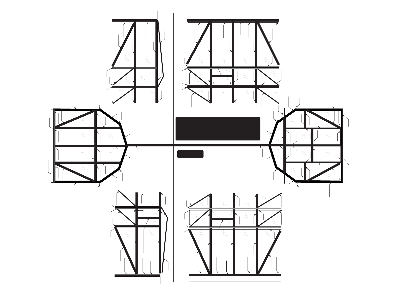
DIAGRAM SHOWS THE ASSEMBLED
601B
THE BOX CONFIGURATION IS AN ELITE 8X8
8X12 GRANDIO ELITE
609
610
609
630
610610
601A-B
L08B-X
L08A
PLUS A 4 FOOT EXTENSION KIT
606-WS 606-WS
603C603C
Y5-1Y5-2
BACK
Y1 Y1Y1 Y1
606-WS
the base for 8x8 is all in GRA-BAS-8.
In boxes GRA-ELI-8A and GRA-ELI-8P,
BA-S1
606-WS
L08B-X
L08B
603C 603C
602D 602D
602C
607
601B
630
Outside View
601B 601B
610
601A-B
630
609
610
Y11
L08E-X
L08D-X
602B
602B
Y11
609
Y8
609
630
L08D-X
610
L08E-X
Y8
602B
Y11
Y11
602B
Y11
618
602B
Y9 Y10
602B
Y8
602B
Y11
602B
618
602B
Y8
Y9 Y10
602B
601B
L08E-X
L08D-X
601A-FL
609
Y7
L08C-X
606-WS
602A
Y7
603C/616
606-WS
BA-S5
4X Elite Side
602A
AZ1
609
Y7
L08M-X
606-WS
7
602A
Y7
603C/616
606-WS
602A
BA-S2
Y7
606-WS
8x8 Elite Side
602A
Y7
609
606-WS
L08C-X
LEFT SIDE
the base for 8x8 is all in GRA-BAS-8.
In boxes GRA-ELI-8A and GRA-ELI-8P,
(8’ Extension Side) (GRA-ELI-8XA & GRA-ELI-8XP)
Elite 8’ Side Extension includes Base
(8’x8’ Original Kit) (GRA-ELI-8A & GRA-ELI-8P & GRA-BAS-8)
8x8 Elite Includes Front, Back, Base, and Sides
602A
602B
602B
BA-S4
Y7
Y8
Y11
606-WS
602A
602B
Y8
602B
606-WS
Y7
Y11
602A
AZ1
602B
602B
609
610
609
630
L08M-X
L08D-X
Y8
Y11
L08E-X
606-WS
Y7
602A
602B
602B
606-WS
603C/616
Y7
618
Y11
609
610
609
630
606-WS
L08C-X
L08D-X
Y11
L08E-X
606-WS
602A
603C/616
602B
602B
618
Y11
Y7
Y10 Y9
Y7
610
601A-B
601B
630
Y4-1Y4-2
L08A
L08B-X
606-WS
601B
Y5-1Y5-2
L08B
603C603C
603C 603C
602D 602D
602C
607
601B
630
606-WS
BACK
606-WS
the base for 8x8 is all in GRA-BAS-8.
In boxes GRA-ELI-8A and GRA-ELI-8P,
BA-S1
606-WS
L08B-X
Y1 Y1Y1 Y1
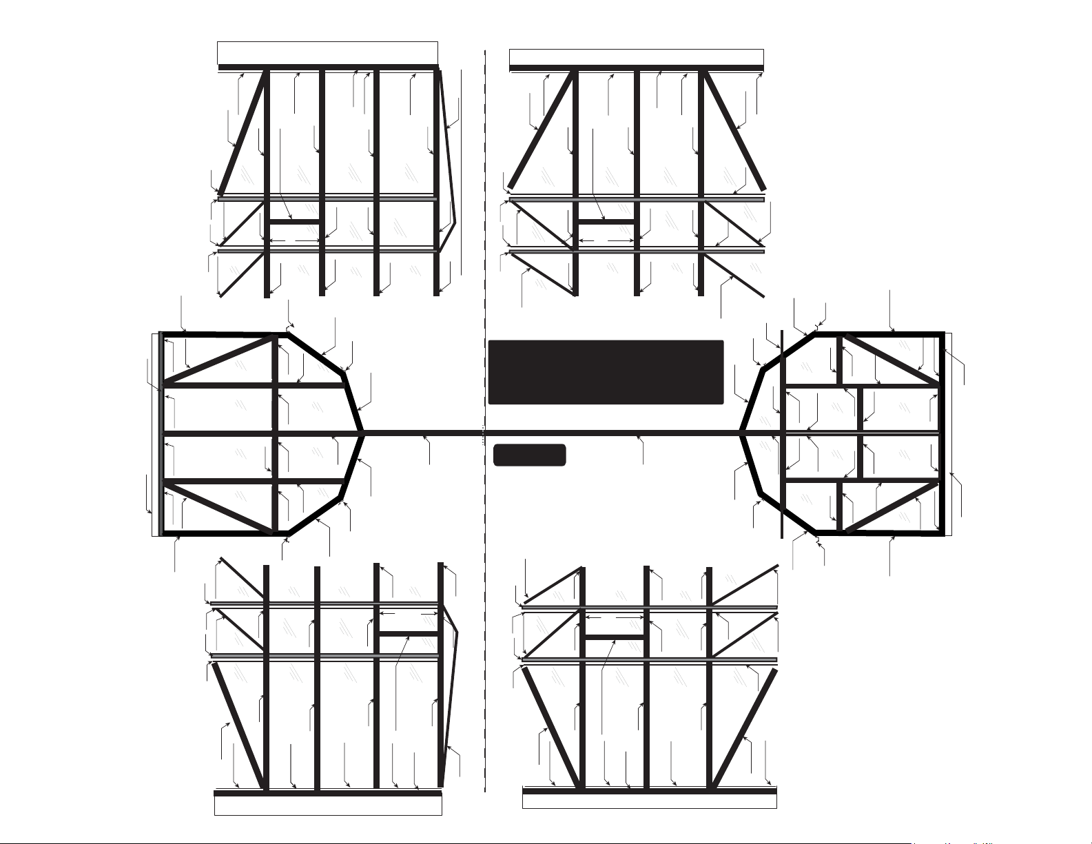
DIAGRAM SHOWS THE ASSEMBLED
8X16 GRANDIO ELITE
THE BOX CONFIGURATION IS AN ELITE 8X8
PLUS AN 8 FOOT EXTENSION KIT
Outside View
Y10 Y9
602A
610
607
BA-S2
602B
602B
Y7
Y8
606-WS
Y11
602A
602B
602B
Y7
609
L08E-X
601B
601B
606-WS
L08C-X
609
Y8
Y11
630630
Y3-1 Y3-2
RIGHT SIDE
L08D-X
In boxes GRA-ELI-8A and GRA-ELI-8P,
601B
L21
Y2-2Y2-1
603D
623A 623A
603E
the base for 8x8 is all in GRA-BAS-8.
610
622-R
622-L
L08D
Y6 Y6
L08D
603C
622
622
603C
604-R
620
620
604-L
601A-FR
Y6 Y6Y1 Y1
L08A-X
606-WS
623B
623B
606-WS
L08A-X
619
FRONT
BA-S1
the base for 8x8 is all in GRA-BAS-8.
In boxes GRA-ELI-8A and GRA-ELI-8P,
601A-B
630
609
610
609
L08E-X
L08D-X
L08C-X
606-WS
602B
Y7
602A
606-WS
606-WS
601B
Y11
Y8
Y7
606-WS
602B
602A
602B
Y11
618
Y7
603C/616
606-WS
(8’ Extension Side) 8X Elite Side
Y9 Y10
BA-S3
602A
602B
602B
AZ1
610
601B
L08E-X
630
609
L08D-X
610
609
8
Y11
Y8
Y7
L08M-X
606-WS
602B
602B
602A
Y11
618
Y9 Y10
Y7
603C/616
606-WS
BA-S2
602A
602B
602B
Y11
Y8
Y7
606-WS
8x8 Elite Side
602B
602B
602A
Y11
609
Y7
Y8
609
606-WS
L08C-X
L08E-X
L08D-X
LEFT SIDE
the base for 8x8 is all in GRA-BAS-8.
In boxes GRA-ELI-8A and GRA-ELI-8P,
601A-FL
610
Y11
Y8
602B
Y11
Y8
Y7
602A

(4’ Extension Side) (GRA-ELI-4X)
Elite 4’ Side Extension
Includes Base
(8’ Extension Side) (GRA-ELI-8XA & GRA-ELI-8XP)
Elite 8’ Side Extension includes Base
(8’x8’ Original Kit) (GRA-ELI-8A & GRA-ELI-8P & GRA-BAS-8)
8x8 Elite Includes Front, Back, Base, and Sides
602A
606-WS
602B
602B
607
Y11
Y8
Y7
606-WS
BA-S4
Y7
Y8
Y11
602A
602B
602B
602A
Y7
Y8
602B
602B
618
603C/616
606-WS
606-WS
602A
Y11
Y11
Y9 Y10
Y7
BA-S3
602A
AZ1
602B
602B
602B
602B
AZ1
607
609
610
609
630
630
609
610
609
606-WS
606-WS
L08M-X
L08D-X
L08E-X
L08E-X
Y8
L08D-X
L08M-X
Y8
Y11
601B
601B
Y11
Y7
606-WS
602A
603C/616
Y7
630
Y3-1 Y3-2
630
602B
602B
602A
602B
602B
L21
603D
601B
603E
601B
603C/616
606-WS
Y7
618
Y11
Y2-2Y2-1
623A
623A
Y11
618
Y7
BA-S2
BA-S6
606-WS
L08C-X
Y7
609
610
L08D-X
609
630
601A-B
606-WS
L08A
606-WS
BACK
606-WS
the base for 8x8 is all in GRA-BAS-8.
In boxes GRA-ELI-8A and GRA-ELI-8P,
BA-S1
606-WS
L08B-X
601A-B
630
609
609
L08E-X
L08B-X
L08E-X
610
L08D-X
Y8
Y11
Y1 Y1Y1 Y1
Y11
Y8
Y7
L08C-X
606-WS
602A
602B
602B
602B
602A
Y8
L08B
610
602B
603C/616
606-WS
606-WS
Y7
610
603C603C
603C 603C
Y11
618
Y7
BA-S5
Y11
602D 602D
Y9 Y10
602A
Y5-1Y5-2
602A
Y4-1Y4-2
AZ1
602B
602B
601B
602C
601B
602B
602B
AZ1
630
630
601B
601B
607
602A
602B
606-WS
603C/616
Y7
Y10 Y9
618
Y11
602B
609
610
609
630
L08M-X
L08D-X
Y11
L08E-X
606-WS
Y7
DIAGRAM SHOWS THE ASSEMBLED
8X20 GRANDIO ELITE
THE BOX CONFIGURATION IS AN ELITE 8X8
PLUS AN 8 FOOT AND A 4 FOOT EXTENSION KIT
Outside View
630
L08E-X
609
610
609
L08D-X
L08M-X
606-WS
Y11
Y8
Y7
602B
602A
Y11
Y8
Y7
606-WS
602B
602A
(8’ Extension Side) 8X Elite Side
(4’ Extensions Side) 4X Elite Side
9
Y10 Y9
610
622-R
622-L
610
Y9 Y10
602A
602A
L08D
Y6 Y6
L08D
BA-S2
602B
602B
603C
622
622
603C
602B
602B
606-WS
Y7
Y8
Y11
Y8
Y7
606-WS
Y11
604-R
620
620
604-L
8x8 Elite Side
602A
602B
602B
601A-FR
Y6 Y6Y1 Y1
601A-FL
602B
602B
602A
Y11
609
Y7
609
L08E-X
L08A-X
606-WS
623B
623B
606-WS
L08A-X
Y8
Y7
L08C-X
606-WS
L08C-X
609
Y8
Y11
609
606-WS
L08D-X
619
FRONT
BA-S1
L08E-X
L08D-X
RIGHT SIDE
the base for 8x8 is all in GRA-BAS-8.
In boxes GRA-ELI-8A and GRA-ELI-8P,
the base for 8x8 is all in GRA-BAS-8.
In boxes GRA-ELI-8A and GRA-ELI-8P,
LEFT SIDE
the base for 8x8 is all in GRA-BAS-8.
In boxes GRA-ELI-8A and GRA-ELI-8P,
(8’ Extension Side) (GRA-ELI-8XA & GRA-ELI-8XP)
Elite 8’ Side Extension includes Base
(8’ Extension Side) (GRA-ELI-8XA & GRA-ELI-8XP)
Elite 8’ Side Extension includes Base
(8’x8’ Original Kit) (GRA-ELI-8A & GRA-ELI-8P & GRA-BAS-8)
8x8 Elite Includes Front, Back, Base, and Sides
602A
606-WS
602B
602B
607
Y11
Y8
BA-S4
Y7
Y8
Y11
602A
602B
602B
Y8
602B
602B
606-WS
Y7
Y11
Y11
618
Y9 Y10
602A
AZ1
602B
602B
602B
602B
607
609
610
609
630
630
609
610
606-WS
L08D-X
L08E-X
L08E-X
Y8
L08D-X
L08M-X
Y7
Y8
Y11
601B
601B
Y11
630
630
602A
602B
602B
L21
Y3-1 Y3-2
602B
602B
603C/616
Y7
618
Y11
601B
Y2-2Y2-1
603D
623A
623A
603E
601B
Y11
618
BA-S4
618
Y11
606-WS
602A
Y10 Y9
L08B
602B
610
602B
602B
610
603C603C
603C 603C
Y11
Y8
Y7
Y8
Y11
Y5-1Y5-2
602D 602D
Y7
602A
602B
Y4-1Y4-2
602B
601B
602C
601B
Y8
602B
630
602B
606-WS
Y7
Y11
630
Y11
618
606-WS
L08C-X
609
Y7
610
L08D-X
609
630
Y11
L08E-X
L08B-X
L08A
606-WS 606-WS
BACK
606-WS
the base for 8x8 is all in GRA-BAS-8.
In boxes GRA-ELI-8A and GRA-ELI-8P,
BA-S1
606-WS
L08B-X
630
L08E-X
Y11
609
610
L08D-X
Y8
602A
602B
601A-B
601A-B
602B
606-WS
603C/616
602B
Y1 Y1Y1 Y1
Y11
Y8
601B
601B
Y9 Y10
602A
AZ1
602B
602B
602B
602B
607
609
610
609
630
L08E-X
606-WS
L08M-X
Y7
L08D-X
Y11
602A
602B
606-WS
603C/616
Y7
618
Y11
602B
Y10 Y9
DIAGRAM SHOWS THE ASSEMBLED
8X24 GRANDIO ELITE
THE BOX CONFIGURATION IS AN ELITE 8X8
PLUS (2) 8 FOOT EXTENSION KITS
Outside View
630
L08E-X
609
610
L08D-X
Y11
Y8
602B
Y11
Y8
602B
606-WS
602A
Y10 Y9
610
622-R
622-L
610
Y9 Y10
L08D
Y6 Y6
L08D
602B
602B
603C
622
622
603C
602B
602B
BA-S2
Y7
Y8
Y11
Y11
Y8
604-R
620
620
604-L
606-WS
602A
602B
602B
601A-FR
Y6 Y6Y1 Y1
601A-FL
602B
602B
L08E-X
Y11
609
Y7
609
L08A-X
606-WS
623B
623B
606-WS
L08A-X
Y8
606-WS
L08C-X
609
Y8
Y11
BA-S1
L08E-X
L08D-X
619
FRONT
In boxes GRA-ELI-8A and GRA-ELI-8P,
L08D-X
RIGHT SIDE
the base for 8x8 is all in GRA-BAS-8.
In boxes GRA-ELI-8A and GRA-ELI-8P,
the base for 8x8 is all in GRA-BAS-8.
609
Y7
L08C-X
606-WS
602A
Y7
602A
606-WS
Y7
606-WS
602A
Y7
603C/616
606-WS
BA-S3
(8’ Extension Side) 8X Elite Side
602A
AZ1
609
Y7
L08M-X
606-WS
602A
Y7
602A
606-WS
Y7
606-WS
10
602A
Y7
603C/616
606-WS
BA-S3
(8’ Extension Side) 8X Elite Side
602A
AZ1
609
Y7
L08M-X
606-WS
602A
Y7
603C/616
606-WS
BA-S2
602A
Y7
606-WS
Y7
609
606-WS
LEFT SIDE
the base for 8x8 is all in GRA-BAS-8.
In boxes GRA-ELI-8A and GRA-ELI-8P,
602A
L08C-X
8x8 Elite Side

BASE KIT ASSEMBLY INSTRUCTIONS
Pre-Plan The Placement Of Your Structure
Allow enough room to get a wheel barrow in and around your structure.
Be sure the orientation will allow for proper drainage in and around your greenhouse.
It is recommended that you place your greenhouse in an area of your property that receives the most sunlight but is also somewhat protected
by trees, fencing or your home for wind protection and also to keep the temperature up during early spring and late fall.
The best placement depends on the features of your property, it is suggested in most scenarios to have your greenhouse face South on its
broadest side and to have the door face East or West depending on typical wind directions in your area. Do not worry if your orientation will
not allow for the placement to be as suggested, as a greenhouse that is facing North is better than no greenhouse at all.
Avoid building your greenhouse at the base of a slope as these are often frost pockets where cold air collects, this will not be good for your
greenhouse in keeping the temperature up inside.
Extreme Wind Conditions: If you live in a windy location there is no way to build a 100% storm safe greenhouse, but there are a number
of things you can do to minimize the chance of damage. Ensure that the base is level and square, be sure all panels are tightly in place and that
all aluminum extrusions are tight. The main problem is usually that wind gets into the greenhouse and the pressure pushes a panel out and
then the force of the wind on the interior causes more damage. It is best if you are expecting an extreme weather event that you disable any
auto roof vents and make sure all doors and windows are closed and locked shut. Also you may need to build a wind break for extreme condition areas where wind is constant and extreme.
See our website GrandioGreenhouses.com for Extreme Weather Anchoring Kits and Moisture Control Kits to aid in protecting your green-
house in the event of harsh weather conditions prior to beginning installation.
It is ideal for your greenhouse to have water, electricity and even gas plumbed into place before construction. This will make watering plants
and keeping the temperature and air circulation to the max eciency.
You will need to choose an anchoring system prior to installation, see our website for options:
www.GrandioGreenhouses.com
For Cement Base Installation: We recommend you use wedge style concrete anchoring bolts to secure your structure.
For Deck Base Installation: We recommend you use anchoring bolts to secure your structure.
For Earth Installation: We recommend you use the BA-A1 / L-BOLT anchoring system, and bury corner posts into the ground and seal into
place with quickrete.
11
BASE KIT PARTS LIST
8X8 BASE KIT PARTS WILL BE FOUND IN
(GRA-BAS-8) BOX
GRAPHIC PART NAME SIZE/LOCATION QUANTITY
BA-S1
BA-S2
BA-C3
BA-S03
ML01
W05
97 3/8 in / 2474 mm
94/4 in / 2394 mm
5 7/16 in 138 mm
M6*14
NUT
CLIPS
2
2
4
28
28
9
PARTS WILL BE FOUND IN (GRA-ELI-4X) BOX
FOR THE 4’ EXTENSION BASE KIT
GRAPHIC PART NAME SIZE/LOCATION QUANTITY
BA-S5
BA-S6
BA-C4
BA-S10
BA-S03
ML01
46 3/4 in / 1187 mm
46 3/4 in / 1187 mm
8 7/16 in / 214 mm
1/2 x 3/4
M6*14
NUT
1
1
2
2
16
16
PARTS LIST FOR BASE KIT
12

BASE KIT PARTS LIST
PARTS WILL BE FOUND IN (GRA-ELI-8XA) BOX
FOR THE 8’ EXTENSION BASE KIT
GRAPHIC PART NAME SIZE/LOCATION QUANTITY
PARTS LIST FOR BASE KIT
BA-S3
BA-S4
BA-C4
BA-S10
BA-S03
ML01
93 7/16 in / 2374 mm
93 7/16 in / 2374 mm
8 7/16 in /214 mm
1/2 X 3/4
M6*14
NUT
1
1
2
2
16
16
13
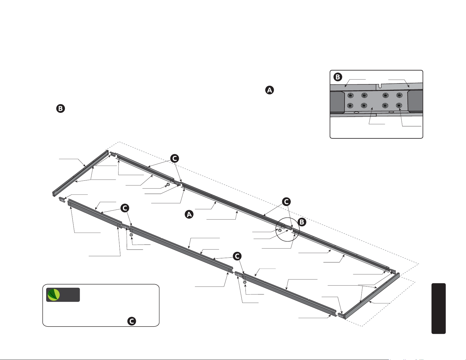
8x12 BASE KIT ASSEMBLY INSTRUCTIONS
(GRA-BAS-8) AND (GRA-ELI-4X)
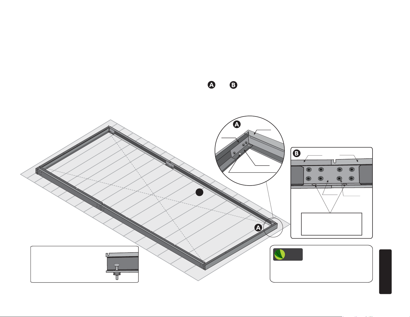
1.1 Layout all base kit pieces to prepare for assembly. Note that one BA-S1 will be at the front
and one BA-S1 will be at the back and the BA-S2’s will be on the sides attaching to the front
BA-S1. The BA-S5 and BA-S6 will attach to the back BA-S1, See diagram .
1.2 Attach the BA-S2 to the BA-S5 with the BA-C4 using the BA-S03 and ML01.
See . Repeat for other side connecting the BA-S6 and the BA-S2.
Go to page 18 for the next step.
BA-S1
BA-C3
BA-C3
BA-S6
HOLE FOR
ANCHOR
HOLE FOR
ANCHOR
HOLE FOR
ANCHOR
HOLE FOR
ANCHOR
BA-S5
BA-S10
BA-C4
BA-S10
BA-C4
HOLE FOR
ANCHOR
BA-S2
HOLE FOR
ANCHOR
BA-S2
HOLE FOR
ANCHOR
BA-C3
143
3/4
” / 3652 mm
HOLE FOR
ANCHOR
HOLE FOR
ANCHOR
BA-C3
BA-S5
BA-C4
BA-S2
BA-S03
ML01
GRANDIO
TIP
sides have about a 2 foot gap between
each, so be sure base kit extensions
are assembled properly. See .
Note that the holes for
screws on the base kit
HOLE FOR
ANCHOR
14
BA-S1
97
”
7/16
/ 2475 mm
STEP ONE
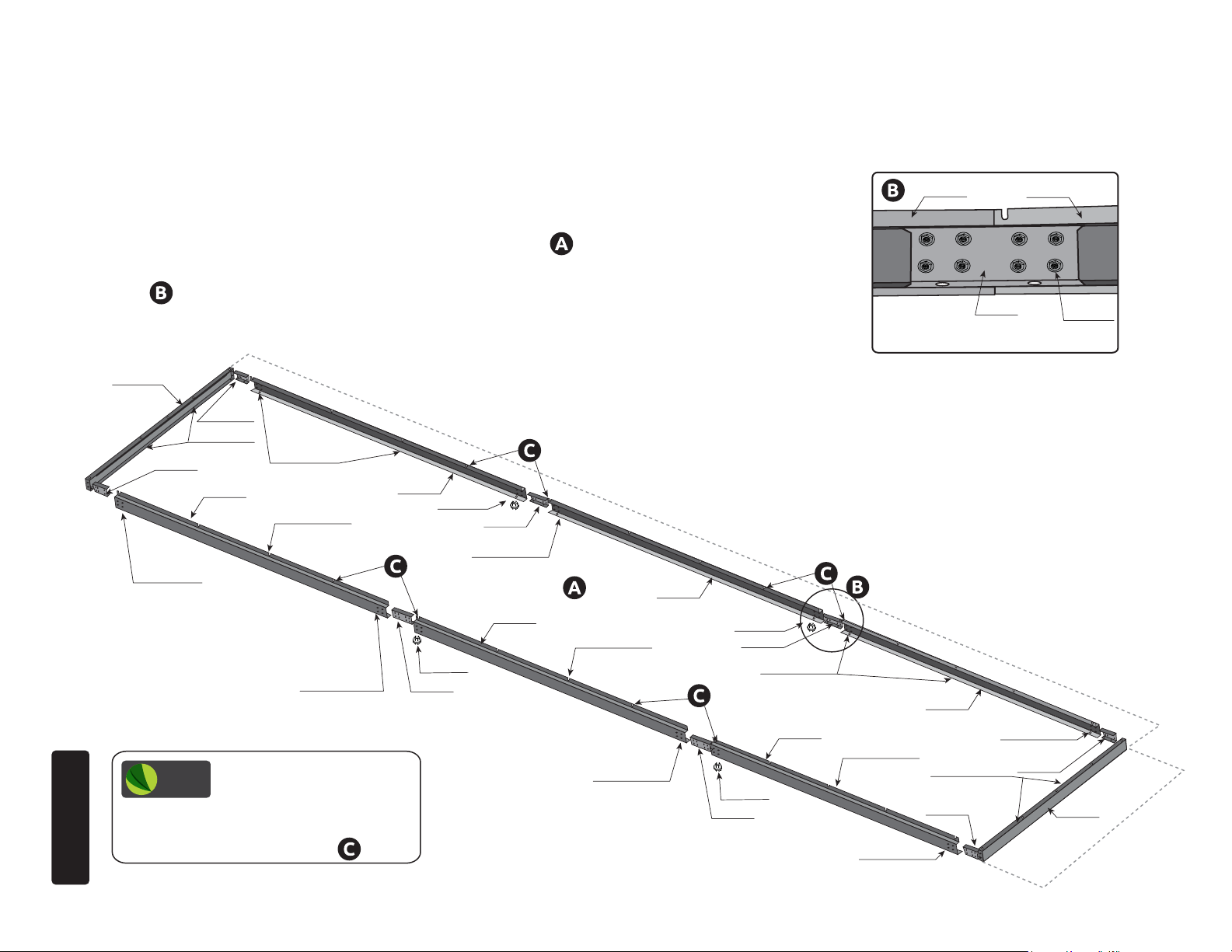
8x16 BASE KIT ASSEMBLY INSTRUCTIONS
(GRA-BAS-8) AND (GRA-ELI-8XA)
1.3 Layout all base kit pieces to prepare for assembly. Note that one BA-S1 will be at the front
and one BA-S1 will be at the back and the BA-S2’s will be on the sides attaching to the front
BA-S1. The BA-S3 and BA-S4 will attach to the back BA-S1 See diagram .
1.4 Attach the BA-S2 to the BA-S3 with the BA-C4 using the BA-S03 and ML01.
See . Repeat for other side connecting the BA-S4 and the BA-S2.
Go to page 18 for the next step.
BA-S1
BA-C3
HOLE FOR
ANCHOR
GRANDIO
TIP
sides have about a 2 foot gap between
each, so be sure base kit extensions
STEP ONE
are assembled properly. See .
Note that the holes for
screws on the base kit
BA-C3
HOLE FOR
ANCHOR
BA-S4
HOLE FOR
ANCHOR
HOLE FOR
ANCHOR
HOLE FOR
ANCHOR
BA-S3
HOLE FOR
ANCHOR
BA-S10
BA-C4
BA-S10
BA-C4
HOLE FOR
ANCHOR
HOLE FOR
ANCHOR
190
15/16
BA-S2
HOLE FOR
ANCHOR
BA-S2
HOLE FOR
ANCHOR
” / 4849 mm
HOLE FOR
ANCHOR
BA-C3
BA-S3
HOLE FOR
ANCHOR
BA-C3
BA-C4
BA-S1
BA-S2
97
”
7/16
BA-S03
ML01
/ 2475 mm
15
8x20 BASE KIT ASSEMBLY INSTRUCTIONS
(GRA-BAS-8) AND (GRA-ELI-8XA) AND (GRA-ELI-4X)
1.5 Layout all base kit pieces to prepare for assembly. Note that one BA-S1 will be at the front
and one BA-S1 will be at the back and the BA-S2’s will be on the sides attaching to the front
BA-S1. The BA-S5 and BA-S6 will attach to the back BA-S1, See diagram .
1.6 Attach the BA-S2 to the BA-S3 with the BA-C4 using the BA-S03 and BA-M03.
See . Repeat for other side connecting the BA-S4 and the BA-S2, then BA-S3 to BA-S5
and BA-S4 to BA-S6.
Go to page 18 for the next step.
BA-S1
BA-C3
BA-S6
HOLE FOR
ANCHOR
BA-S5
BA-S10
BA-C4
BA-S10
BA-C4
HOLE FOR
ANCHOR
BA-S3
HOLE FOR
ANCHOR
HOLE FOR
ANCHOR
BA-S4
HOLE FOR
ANCHOR
237
5/8
” / 6036 mm
BA-S10
BA-C4
HOLE FOR
ANCHOR
BA-S2
BA-S10
BA-C4
HOLE FOR
ANCHOR
HOLE FOR
ANCHOR
HOLE FOR
ANCHOR
HOLE FOR
ANCHOR
BA-C3
HOLE FOR
ANCHOR
HOLE FOR
ANCHOR
GRANDIO
TIP
sides have about a 2 foot gap between
each, so be sure base kit extensions
are assembled properly. See .
Note that the holes for
screws on the base kit
BA-S2
HOLE FOR
ANCHOR
BA-C3
BA-S5
BA-C4
HOLE FOR
ANCHOR
BA-C3
BA-S1
7/16
97
BA-S2
/ 2475 mm
”
BA-S03
BA-M03
STEP ONE
16
8x24 BASE KIT ASSEMBLY INSTRUCTIONS
(GRA-BAS-8) AND (GRA-ELI-8XA) AND (GRA-ELI-8XA)
1.7 Layout all base kit pieces to prepare for assembly. Note that one BA-S1 will be at the front
and BA-S1 will be at the back and the BA-S2’s will be on the sides attaching to the front BA-S1.
The BA-S3 and BA-S4 will attach to the back BA-S1. The BA-S3 will attach to the other BA-S3
and BA-S4 will attach to the other BA-S4 See diagram .
1.8 Attach the BA-S2 to the BA-S3 with the BA-C4 using the BA-S03 and ML01.
See . Repeat for other side connecting the BA-S4 and the BA-S2, and then the BA-S3
to the BA-S3, and then the BA-S4 to the BA-S4.
Go to page 18 for the next step.
BA-S1
BA-C3
HOLE FOR
ANCHOR
BA-C3
HOLE FOR
ANCHOR
BA-S4
HOLE FOR
ANCHOR
HOLE FOR
ANCHOR
HOLE FOR
ANCHOR
BA-S3
BA-S10
BA-C4
BA-S10
HOLE FOR
ANCHOR
BA-C4
BA-S4
HOLE FOR
ANCHOR
284
BA-S3
3/8
”/ 7223 mm
BA-S10
BA-C4
HOLE FOR
ANCHOR
BA-S3
BA-S2
BA-C4
BA-S2
BA-S03
ML01
GRANDIO
TIP
sides have about a 2 foot gap between
each, so be sure base kit extensions
are assembled properly. See .
STEP ONE
Note that the holes for
screws on the base kit
HOLE FOR
ANCHOR
17
BA-S10
BA-C4
BA-S2
HOLE FOR
ANCHOR
HOLE FOR
ANCHOR
HOLE FOR
ANCHOR
BA-C3
HOLE FOR
ANCHOR
BA-C3
BA-S1
97
/ 2475 mm
”
7/16
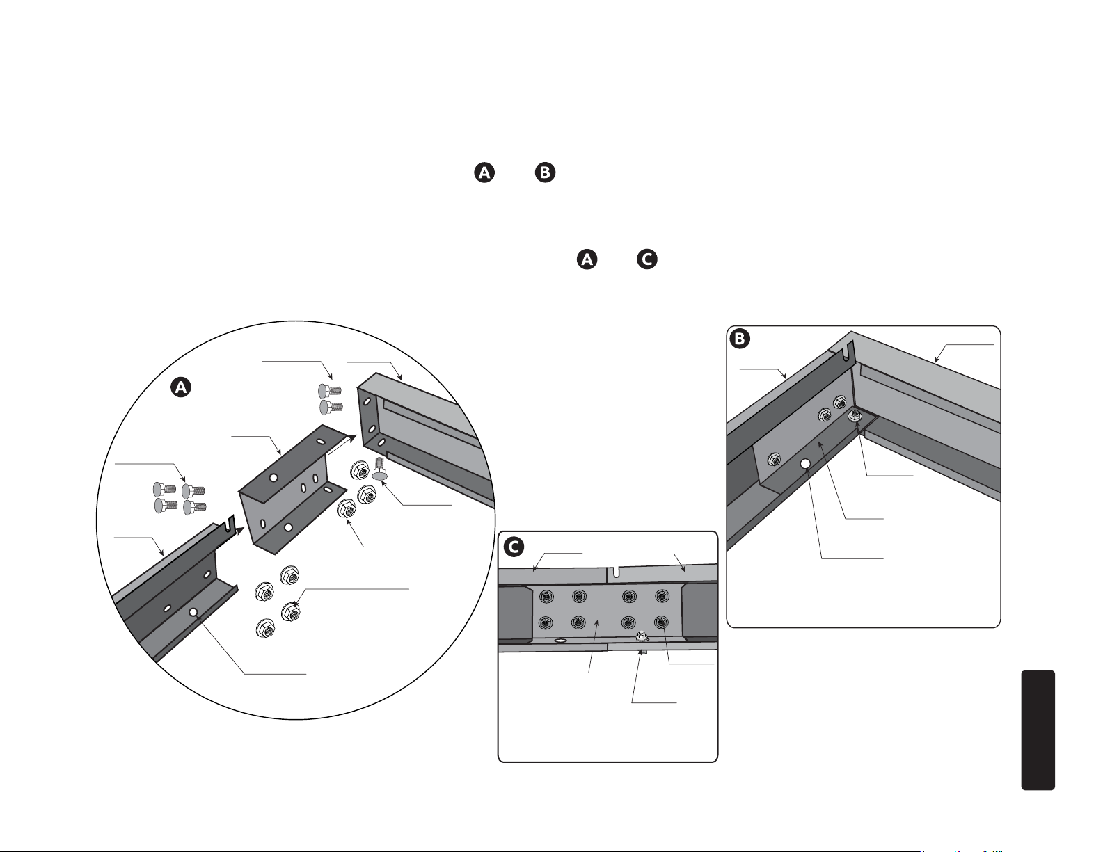
BASE KIT ASSEMBLY INSTRUCTIONS
BA-S1
BA-S2
FRONT
SIDE
BA-C3
BA-C3
BA-S1
BA-S2
BA-S03
ML01 Collared Nut
BA-S03
ML01 Collared Nut
BA-C4
BA-S3
BA-S2
BA-S03
ML01
BA-S10
1.9 Slide the BA-C3 into the BA-S1, slide the BA-S2 into the BA-C3, align the holes and push together to an even and tight
position and use the BA-S03 Bolt and ML01 Collard Nut combo, tighten the collard nut on the inside of the base kit using the
10mm wrench. Repeat this process on all corners. See and .
Note: BA-S1 will be the front and back, while the BA-S2’ s will be the sides of your greenhouse base.
1.10 For Ground Installation only Insert the BA-S03 and the BA-A1 into the holes at the bottom side of the corners
of the base, the nut will be tightened on the inside of base, see and . Locate the anchoring devices for your
installation needs and follow the directions for that anchoring system. If you have not purchased an anchoring
system please go to www.GrandioGreenhouses.com for anchoring kit options.
BA-S03
BA-S03
ML01
HOLE FOR
ANCHOR
HOLE FOR
ANCHOR
STEP ONE
18
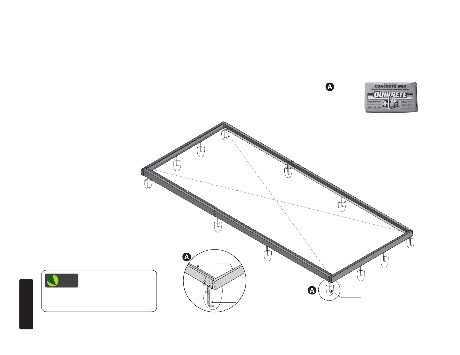
BASE KIT GROUND INSTALLATION
**BASE MUST BE LEVEL & SQUARE,
FOUNDATION MUST BE PROPERLY ANCHORED PRIOR TO GREENHOUSE ASSEMBLY
1.11 If using an L-Bolt / BA-A1 anchoring kit the BA-A1 must be buried in ground. See .
Dig holes to bury the BA-A1’s, you determine size and depth for your location.
We recommend you use: Quikrete fast setting concrete to anchor base. Follow the directions on the package.
See www.GrandioGreenhouses.com for anchoring kit options.
Outdoor
Ground
Assembly
GRANDIO
TIP
anchor into concrete. Use a measuring tape
to ensure all corners are the same. Use level
on all four sides.
STEP ONE
Make sure base is squared
and level before setting
BA-S03
BA-S2
BA-S1
BA-A1
19
BA-A1 * Must be inserted
into the ground, and secured
with concrete.
BA-S1
BA-C3
BA-S2
HOLE FOR ANCHOR
BOLT OR SCREW.
BASE KIT DECK INSTALLATION
If surface is uneven you may want
to purchase large washers that
will fit under the base and allow
fasteners to go through to use as
a shim for leveling the base kit.
**BASE MUST BE LEVEL & SQUARE,
FOUNDATION MUST BE PROPERLY ANCHORED PRIOR TO GREENHOUSE ASSEMBLY
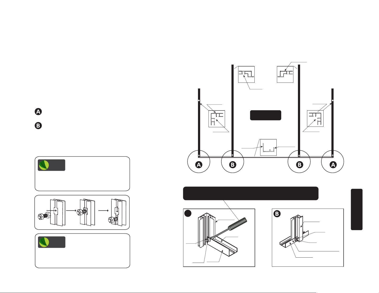
1.12 Holes are present in base kit for anchoring bolts see and .
You determine and acquire proper fastener prior to installation for your surface.
Discard the BA-S10 for deck or concrete slab installation.
See www.GrandioGreenhouses.com for anchoring kit options.
Use lag bolt
or concrete anchors
to attach base.
(Fasteners not included).
Deck or
Patio
Assembly
B
20
BA-S6 BA-S2
BA-C4
Use an appropriate fastener
to attach to your surface
through these access holes.
GRANDIO
TIP
anchors. Use a measuring tape to ensure all
corners are the same. Use level on all four
sides.
Make sure base is squared
and level before setting
BA-S03
ML01
STEP ONE
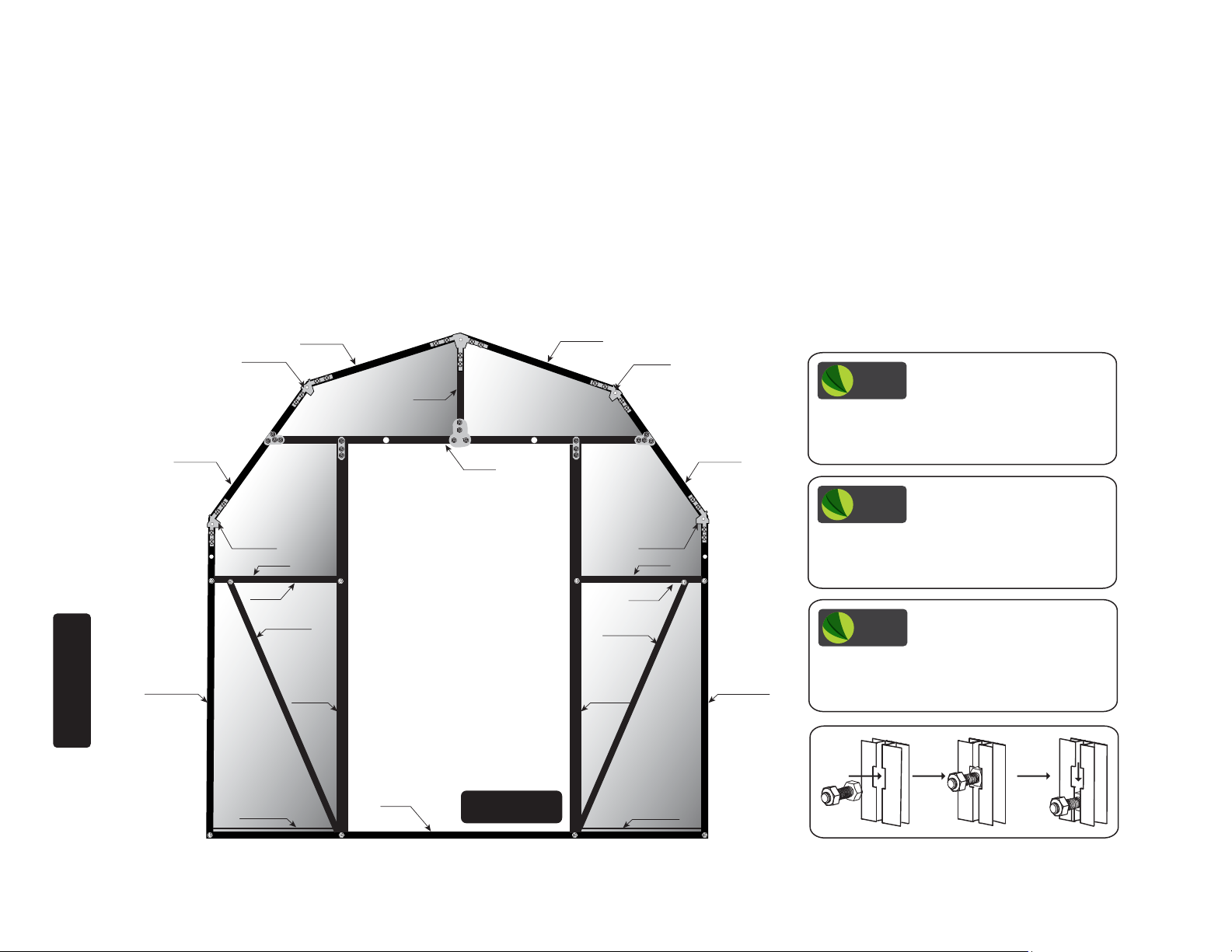
FRONT FRAME ASSEMBLY INSTRUCTIONS
ALWAYS ASSEMBLE FRONT HORIZONTAL
This picture shows the inside view of front section fully assembled.
All parts for front assembly will be found in box GRA-ELI-8A and GRA-ELI-8P.
We recommend that you assemble the front on a tarp.
* If you purchased the Back Door Transformation kit you will repeat this section for your
back wall using parts found in GRA-ELI-BD , GRA-ELI-8A and GRA-ELI-8P boxes.
If you want to purchase the Back Door Transformation kit call 1-866-448-8231.
STEP TWO
601B
WG02
601B
601B
WG02
601B
Y3-2
603E
Y3-1
603D
Y2-2 Y2-1
WG02
L08D
603C
L08A-X
601A-FR 601A-FL
604-R
WG02
L08D
603C
L08A-X
604-L
Y1 Y1
GRANDIO
TIP
with tricks and tips for easier assembly and
installation of your Grandio Greenhouse at:
www.grandiogreenhouses.com
GRANDIO
TIP
your greenhouse. If possible try to nd a
shady area protected from the wind. Panels
can burn grass and plants if in direct light.
GRANDIO
TIP
thread and place in the groove of the
extrusion to make installation easier. Move
up or down for exact placement.
We recommend watching
our how to assembly videos
Lay at on ground to
assemble the front frame of
BOLT INSTALLATION TIP:
Locate all nuts and bolts, pre
606-WS
619
Inside View
606-WS
21
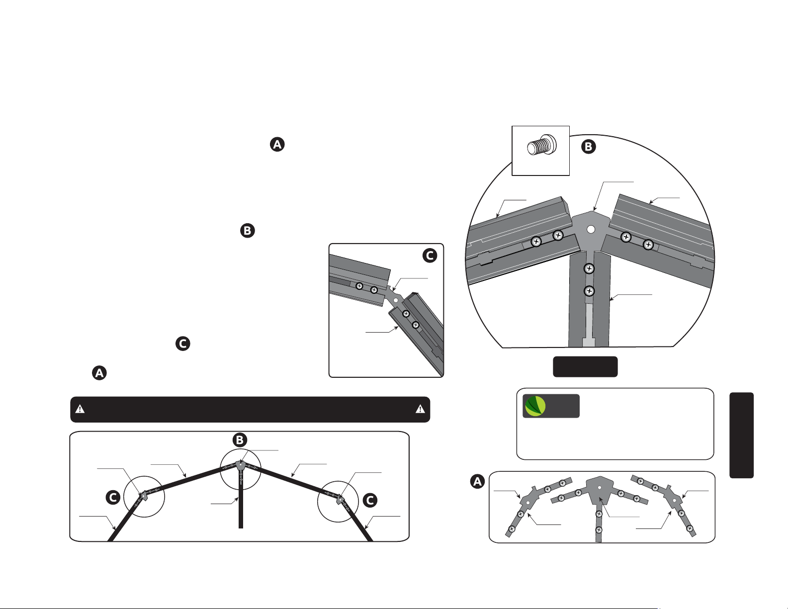
FRONT FRAME ASSEMBLY CONTINUED
ALWAYS ASSEMBLE FRONT HORIZONTAL
2.1 Prethread all S05 screws into the WG01
and WG02’s for ease of installation, see
only turn S05 a few turns. Leave the mid hole
open, as this is for the end cap attachment.
2.2 Use WG01 bracket to attach the (2)
601B’s together with the 603E, secure parts
with the S05 screws provided see . The
WG01 will slide into the groove of the
601B’s, and also slide into the groove of the
603E, screw head will remain outside chan-
nel.
2.3 Install WG02’s into (2) 601B’s then
tighten S05 screws when extrusions are
completely tight see . Note: the fat end of
the WG02 will always be on the bottom side
see .
601B
WG02
601B
S05
WG01
601B
603E
Inside View
IMPORTANT: Use only S05 Screws, other screws may damage frame.
WG01
601B
WG02
601B
603E
601B
WG02
601B
22
FAT
END
GRANDIO
TIP
and S05 screws, pre thread these to make
installation easier. Note that the fat end on
the WG02 will always face downward.
WG02
PRETHREAD SCREWS TIP:
Locate all WG01, WG02,
FAT
END
WG01
WG02
STEP TWO
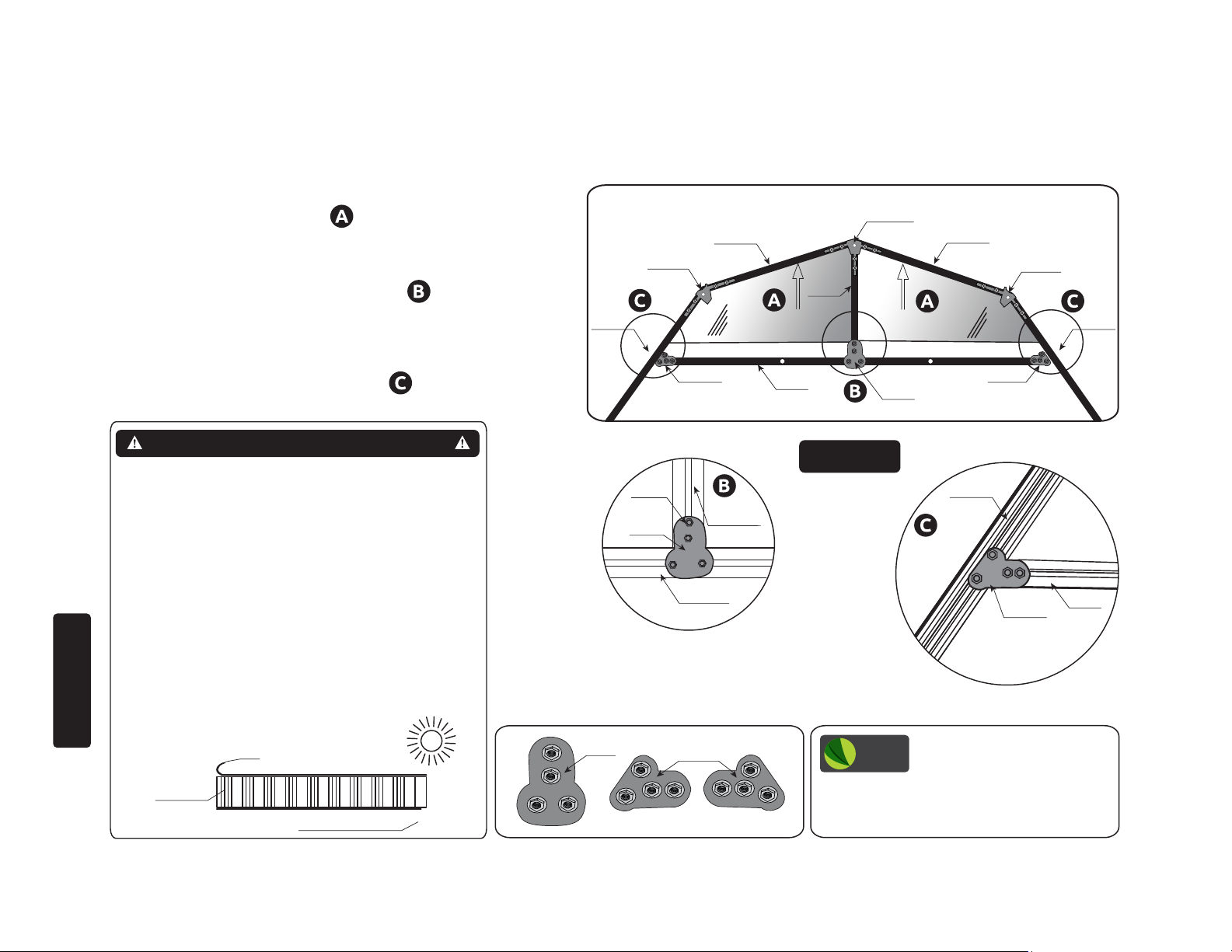
FRONT FRAME ASSEMBLY CONTINUED
ALWAYS ASSEMBLE FRONT HORIZONTAL
*IF USING THE MOISTURE CONTROL KIT YOU WILL USE IT NOW
2.4 Insert polycarbonate panels Y3-2 and
Y3-1 into place as shown in .
2.5 Attach 603E and 603D with W04
and S04/ML01 fasteners as shown in .
2.6 Attach the 603D to the 601B’s
using the W04-1’s with the S04/ML01
fasteners on both sides as shown in .
WG01
601B
WG02
603E
601B 601B
W04-1 W04-1
Y3-2
603D
W04
601B
WG02
Y3-1
IMPORTANT: POLYCARBONATE PANELS
The UV-Protected side is covered with clear lm and
must face toward the sun. The side covered in white lm
will always face the interior of the greenhouse. We
suggest you peel all lm o completely prior to assembly and use a permanent marker to place a small “X” on
the lower right corner of each panel on the clear side
that faces the sun, each panel has a sticker labeling the
panel number and this side always faces the sun or
outward as well. DO NOT REMOVE LABELS UNTIL
YOU INSTALL PANELS. The “X” is suggested in case
you dis-assemble your greenhouse in the future so you
may identify which side has the UV coating. Always use
gloves when handling the polycarbonate panels as the
edges can be very sharp.
STEP TWO
Transparent Clear Film
Polycarbonate
Panels
Opal White Film
Sun
W04
S04
ML01
W04
603D
W04-1
603E
Inside View
601B
W04-1
GRANDIO
TIP
screws, loosely pre thread into the W04 and
W04-1’s and place in the groove of the
extrusion to make installation easier.
BOLT INSTALLATION TIP:
Locate ML01/S04 nuts and
603D
23
FRONT FRAME ASSEMBLY CONTINUED
ALWAYS ASSEMBLE FRONT HORIZONTAL
2.7 View diagrams and attach the (2) 604’s and (2)
601A’s to the 619. Note the orientation of the 604’s,
there are 4 dierent 601A’s (2) for the front and (2) for
the back with dierent hole placements. The large holes
should be at the top and facing forward on the front
frame assembly. See diagram on this page. The 601-FR
and the 601-FL will have a hole at the top side and will
face forward.
shows where the corner pieces attach to 619.
shows where the door frame attaches to the 619.
*If assemblling the back door you will need to drill 1/4”
holes in 601A-B’s to match the front wall, these holes
should face the ground during assembly.
GRANDIO
TIP
thread and place in the groove of the
extrusion to make installation easier. Move
up or down for exact placement.
BOLT INSTALLATION TIP:
Locate all nuts and bolts, pre
604-R 604-L
INSIDE
OUTSIDE
601A-FR
OUTSIDE
OUTSIDE
601A-FL
Inside View
INSIDE
INSIDE
619
OUTSIDE
INSIDE
TIP: If necessary you may use a screwdriver to wedge behind the
bolt head. This prevents bolt from falling into the track.
GRANDIO
TIP
face to the front of greenhouse for future
install of the L21 and L28 bracket that
holds the door header in place.
Make sure the hole on the
601A-FL and 601A-FR
A
ML01
24
S04
INSIDE
601A-FR
Inside View
619
604-R
ML01
S04
INSIDE DOOR FRAME
619
STEP TWO
 Loading...